

Page 1

PS30
Pattern sensor
O P E R A T I N G I N S T R U C T I O N S
Page 2

Described product
PS30
Manufacturer
SICK AG
Erwin-Sick-Str. 1
79183 Waldkirch
Germany
Legal information
This work is protected by copyright. Any rights derived from the copyright shall be
reserved for SICK AG. Reproduction of this document or parts of this document is only
permissible within the limits of the legal determination of Copyright Law. Any modifica‐
tion, abridgment or translation of this document is prohibited without the express writ‐
ten permission of SICK AG.
The trademarks stated in this document are the property of their respective owner.
© SICK AG. All rights reserved.
Original document
This document is an original document of SICK AG.
2
O PE R AT I NG IN S TR U CT I ON S | PS30 8018916.ZYN1/2018-05-17 | SICK
Subject to change without notice
Page 3

Contents
CONTENTS
1 About this document........................................................................ 6
1.1 Information on the operating instructions.............................................. 6
1.2 Scope......................................................................................................... 6
1.3 Explanation of symbols............................................................................ 6
1.4 Further information................................................................................... 7
1.5 Customer service...................................................................................... 7
2 Safety information............................................................................ 8
2.1 Intended use............................................................................................. 8
2.2 Improper use............................................................................................. 8
2.3 Modifications and conversions................................................................ 8
2.4 Limitation of liability................................................................................. 8
2.5 Requirements for skilled persons and operating personnel.................. 9
2.6 Hazard warnings and operational safety................................................. 9
2.7 Repair........................................................................................................ 10
3 Product description........................................................................... 11
3.1 Product ID.................................................................................................. 11
3.2 Product features and functions............................................................... 11
3.3 Operating modes...................................................................................... 12
3.4 Display and operating elements.............................................................. 13
3.5 Display....................................................................................................... 15
3.6 Bar graph................................................................................................... 15
4 Transport and storage....................................................................... 16
4.1 Transport................................................................................................... 16
4.2 Transport inspection................................................................................. 16
4.3 Storage...................................................................................................... 16
5 Mounting............................................................................................. 17
5.1 Scope of delivery....................................................................................... 17
5.2 Mounting requirements............................................................................ 17
5.3 Mounting the device................................................................................. 19
6 Electrical installation........................................................................ 20
6.1 Notes on the electrical installation.......................................................... 20
6.2 Wiring notes.............................................................................................. 21
6.3 Note on the swivel connector................................................................... 23
6.4 System configuration................................................................................ 24
6.5 Connecting the device electrically........................................................... 24
6.6 Pin assignment of the connections......................................................... 25
7 Commissioning.................................................................................. 27
7.1 Pushbutton damage................................................................................. 27
7.2 Steps to take............................................................................................. 27
8018916.ZYN1/2018-05-17 | SICK O P ER A TI N G I NS T RU C TI O NS | PS30
Subject to change without notice
3
Page 4

CONTENTS
7.3 Setting up the encoder............................................................................. 27
7.4 Operation without encoder or machine cycle......................................... 30
8 Operation............................................................................................ 32
8.1 Pushbutton damage................................................................................. 32
8.2 Navigation................................................................................................. 32
8.3 Selecting an option................................................................................... 32
8.4 Changing the value................................................................................... 32
8.5 Settings menu........................................................................................... 33
8.6 Teach menu............................................................................................... 37
8.7 Monitoring menu....................................................................................... 42
8.8 Info menu.................................................................................................. 43
9 Operation via Ethernet TCP/IP........................................................ 44
10 Operation via SOPASair.................................................................... 45
10.1 Integrating the PS30 pattern sensor in the network.............................. 45
10.2 Monitoring menu....................................................................................... 46
10.3 Teach-in menu........................................................................................... 46
10.4 Settings menu........................................................................................... 49
10.5 Device info menu...................................................................................... 50
10.6 Settings menu (of the SOPASair WebUI)................................................. 51
10.7 Analysis menu........................................................................................... 51
11 Troubleshooting................................................................................. 53
11.1 Notes on troubleshooting......................................................................... 53
11.2 Possible error indicators.......................................................................... 53
11.3 Troubleshooting guide.............................................................................. 54
12 Maintenance...................................................................................... 60
12.1 Maintenance............................................................................................. 60
12.2 Cleaning the device.................................................................................. 60
13 Decommissioning............................................................................. 62
13.1 Disassembly and disposal....................................................................... 62
13.2 Returning devices..................................................................................... 62
14 Technical data.................................................................................... 63
14.1 Dimensional drawings.............................................................................. 63
14.2 Optics/features......................................................................................... 63
14.3 Supply........................................................................................................ 64
14.4 Inputs......................................................................................................... 64
14.5 Outputs...................................................................................................... 64
14.6 Interfaces.................................................................................................. 64
14.7 Encoder..................................................................................................... 65
14.8 Ambient conditions................................................................................... 65
14.9 Structural design...................................................................................... 65
4
O PE R AT I NG IN S TR U CT I ON S | PS30 8018916.ZYN1/2018-05-17 | SICK
Subject to change without notice
Page 5

CONTENTS
15 Accessories........................................................................................ 66
15.1 Connectivity............................................................................................... 66
15.2 Mounting systems..................................................................................... 67
16 Menu structure................................................................................... 69
16.1 Setup menu............................................................................................... 69
16.2 Monitr menu.............................................................................................. 69
16.3 Teach menu............................................................................................... 69
16.4 Settng menu.............................................................................................. 70
16.5 Info menu.................................................................................................. 70
17 Annex.................................................................................................. 71
17.1 EU declaration of conformity and certificates........................................ 71
17.2 Certification according to UL60947-5-2................................................. 71
17.3 Licenses.................................................................................................... 71
18 Index.................................................................................................... 72
8018916.ZYN1/2018-05-17 | SICK O P ER A TI N G I NS T RU C TI O NS | PS30
Subject to change without notice
5
Page 6

1 ABOUT THIS DOCUMENT
1 About this document
1.1 Information on the operating instructions
These operating instructions provide important information on how to use devices from
SICK AG.
Prerequisites for safe work are:
Compliance with all safety notes and handling instructions supplied
•
Compliance with local work safety regulations and general safety regulations for
•
device applications
The operating instructions are intended to be used by qualified personnel and electrical
specialists.
NOTE
Read these operating instructions carefully before starting any work on the device, in
order to familiarize yourself with the device and its functions.
The instructions constitute an integral part of the product and are to be stored in the
immediate vicinity of the device so they remain accessible to staff at all times. Should
the device be passed on to a third party, these operating instructions should be handed
over with it.
These operating instructions do not provide information on operating the machine in
which the device is integrated. For information about this, refer to the operating instruc‐
tions of the specific machine.
1.2 Scope
These operating instructions serve to incorporate the device into a customer system.
Instructions are given in stages for all actions required.
These instructions apply to all listed device variants of the product.
Available device variants are listed on the online product page.
www.sick.com/PS30
b
Commissioning is described using one particular device variant as an example.
Simplified device designation in the document
In the following, the sensor is referred to in simplified form as “PS30” or “device”.
1.3 Explanation of symbols
Warnings and important information in this document are labeled with symbols. The
warnings are introduced by signal words that indicate the extent of the danger. These
warnings must be observed at all times and care must be taken to avoid accidents, per‐
sonal injury, and material damage.
DANGER
… indicates a situation of imminent danger, which will lead to a fatality or serious
injuries if not prevented.
6
O PE R AT I NG IN S TR U CT I ON S | PS30 8018916.ZYN1/2018-05-17 | SICK
Subject to change without notice
Page 7

WARNING
… indicates a potentially dangerous situation, which may lead to a fatality or serious
injuries if not prevented.
CAUTION
… indicates a potentially dangerous situation, which may lead to minor/slight injuries if
not prevented.
NOTICE
… indicates a potentially harmful situation, which may lead to material damage if not
prevented.
NOTE
… highlights useful tips and recommendations as well as information for efficient and
trouble-free operation.
1.4 Further information
ABOUT THIS DOCUMENT 1
NOTE
All the documentation available for the device can be found on the online product page
at:
www.sick.com/PS30
b
The following information is available for download from this page:
Type-specific online data sheets for device variants, containing technical data and
•
dimensional drawings
EU declaration of conformity for the product family
•
Dimensional drawings and 3D CAD dimension models in various electronic for‐
•
mats
These operating instructions, available in English and German, and in other lan‐
•
guages if necessary
Other publications related to the devices described here
•
Publications dealing with accessories
•
IO-Link driver files and IO-Link Technical Information v1.1
•
1.5 Customer service
If you require any technical information, our customer service department will be happy
to help. To find your agency, see the final page of this document.
NOTE
Before calling, make a note of all type label data such as type code, serial number, etc.,
to ensure faster processing.
8018916.ZYN1/2018-05-17 | SICK O P ER A TI N G I NS T RU C TI O NS | PS30
Subject to change without notice
7
Page 8

2 SAFETY INFORMATION
2 Safety information
2.1 Intended use
The PS30 pattern sensor is an opto-electronic sensor intended for non-contact recogni‐
tion of recurring patterns. A machine cycle as the input signal, e.g., via an encoder or a
motor feedback system, is required to operate the pattern sensor.
Alternatively, the speed of the material can be stored as a constant. This alternative is
intended for applications with a constant or only slowly changing material speed.
SICK AG assumes no liability for losses or damage arising from the use of the product,
either directly or indirectly. This applies in particular to use of the product that does not
conform to its intended purpose and is not described in this documentation.
2.2 Improper use
The device does not constitute a safety-relevant device according to the EC
•
Machinery Directive (2006/42/EC).
The device must not be used in explosion-hazardous areas.
•
Any other use that is not described as intended use is prohibited.
•
Any use of accessories not specifically approved by SICK AG is at your own risk.
•
The device is not suitable for the following applications (this list is not exhaustive):
As a safety device to protect persons, their hands, or other body parts
•
Underwater
•
In explosion-hazardous areas
•
Outdoors, without additional protection
•
NOTICE
Danger due to improper use!
Any improper use can result in dangerous situations.
Therefore, observe the following information:
The device should be used only in line with intended use specifications.
b
All information in these operating instructions must be strictly complied with.
b
2.3 Modifications and conversions
Modifications and conversions to the pattern sensor and/or the installation may result
in unforeseeable dangers.
Before any technical modifications to and expansions of the pattern sensor, the prior
written approval of the manufacturer must be obtained.
2.4 Limitation of liability
Applicable standards and regulations, the latest state of technological development,
and our many years of knowledge and experience have all been taken into account
when assembling the data and information contained in these operating instructions.
The manufacturer accepts no liability for damage caused by:
■
Failure to observe the operating instructions
■
Improper use
■
Use by untrained personnel
■
Unauthorized conversions
■
Technical modifications
■
Use of unauthorized spare parts, wear and tear parts, and accessories
8
O PE R AT I NG IN S TR U CT I ON S | PS30 8018916.ZYN1/2018-05-17 | SICK
Subject to change without notice
Page 9

With special variants, where optional extras have been ordered, or owing to the latest
technical changes, the actual scope of delivery may vary from the features and illustra‐
tions shown here.
2.5 Requirements for skilled persons and operating personnel
WARNING
Risk of injury due to insufficient training!
Improper handling of the device may result in considerable personal injury and material
damage.
■
All work must only ever be carried out by the stipulated persons.
The operating instructions state the following qualification requirements for the various
areas of work:
■
Instructed personnel have been briefed by the operating entity about the tasks
assigned to them and about potential dangers arising from improper action.
■
Skilled personnel have the specialist training, skills, and experience, as well as
knowledge of the relevant regulations, to be able to perform tasks assigned to
them and to detect and avoid any potential dangers independently.
■
Electricians have the specialist training, skills, and experience, as well as knowl‐
edge of the relevant standards and provisions to be able to carry out work on elec‐
trical systems and to detect and avoid any potential dangers independently. In Ger‐
many, electricians must meet the specifications of the BGV A3 Work Safety Regu‐
lations (e.g., Master Electrician). Other relevant regulations applicable in other
countries must be observed.
SAFETY INFORMATION 2
The following qualifications are required for various activities:
Activities Qualification
Mounting, maintenance
Electrical installation,
device replacement
Basic practical technical training
■
Knowledge of the current safety regulations in the workplace
■
Practical electrical training
■
Knowledge of current electrical safety regulations
■
Knowledge of the operation and control of the devices in
■
their particular application
Commissioning,
configuration
Basic knowledge of the design and setup of the described
■
connections and interfaces
Basic knowledge of data transmission
■
Knowledge of the operation and control of the devices in
■
their particular application
Operation of the devices in
their particular application
Knowledge of the operation and control of the devices in
■
their particular application
Knowledge of the software and hardware environment in the
■
application
2.6 Hazard warnings and operational safety
Please observe the safety notes and the warnings listed here and in other chapters of
these operating instructions to reduce the possibility of risks to health and avoid dan‐
gerous situations.
8018916.ZYN1/2018-05-17 | SICK O P ER A TI N G I NS T RU C TI O NS | PS30
Subject to change without notice
9
Page 10

2 SAFETY INFORMATION
2.6.1 Eye safety
CAUTION
The device is equipped with LEDs. The device meets the criteria of risk group 1 accord‐
ing to IEC 62471:2006. No special measures are required (e.g., eye protection).
2.7 Repair
The product is a replacement device. The device is not intended to be repaired. Interfer‐
ence with or modifications to the device on the part of the customer will invalidate any
warranty claims against SICK AG.
10
O PE R AT I NG IN S TR U CT I ON S | PS30 8018916.ZYN1/2018-05-17 | SICK
Subject to change without notice
Page 11
3 Product description
1
2
3 5
4
1
2
2
5
3
4
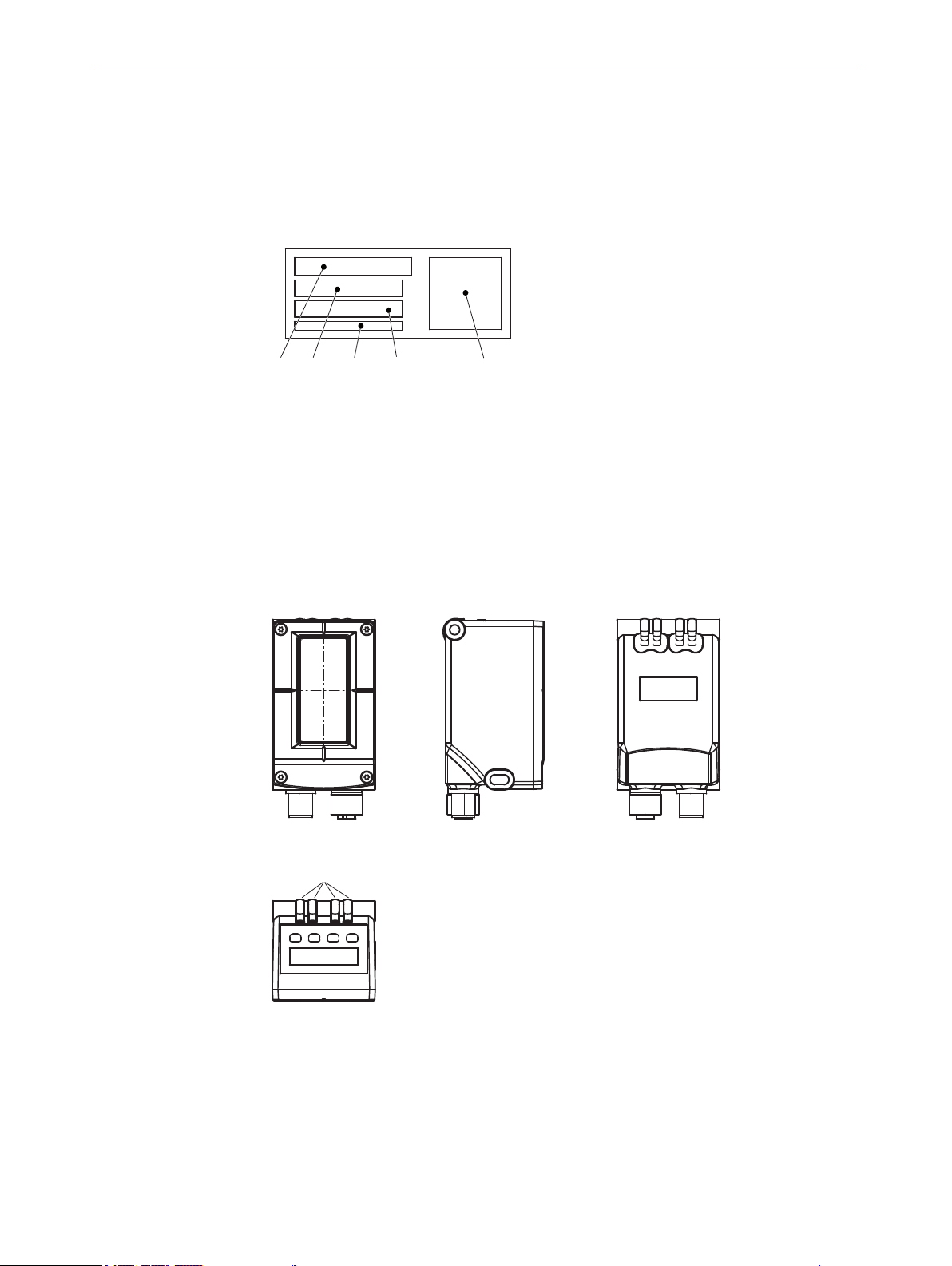
3.1 Product ID
3.1.1 Type label
The type label is located on the back of the pattern sensor.
Figure 1: Type label
Type designation
1
Material number
2
MAC address
3
Serial number
4
Machine-readable code
5
PRODUCT DESCRIPTION 3
3.2 Product features and functions
3.2.1 Device view
Figure 2: PSS Prime light emission long housing side
Center of the optical axis
1
Fixing hole
2
M12 male connector, 12-pin/M12 female connector, 4-pin, rotatable
3
Function indicators
4
Display and control unit
5
8018916.ZYN1/2018-05-17 | SICK O P ER A TI N G I NS T RU C TI O NS | PS30
Subject to change without notice
11
Page 12

1
2
3 PRODUCT DESCRIPTION
3.2.2 Product characteristics
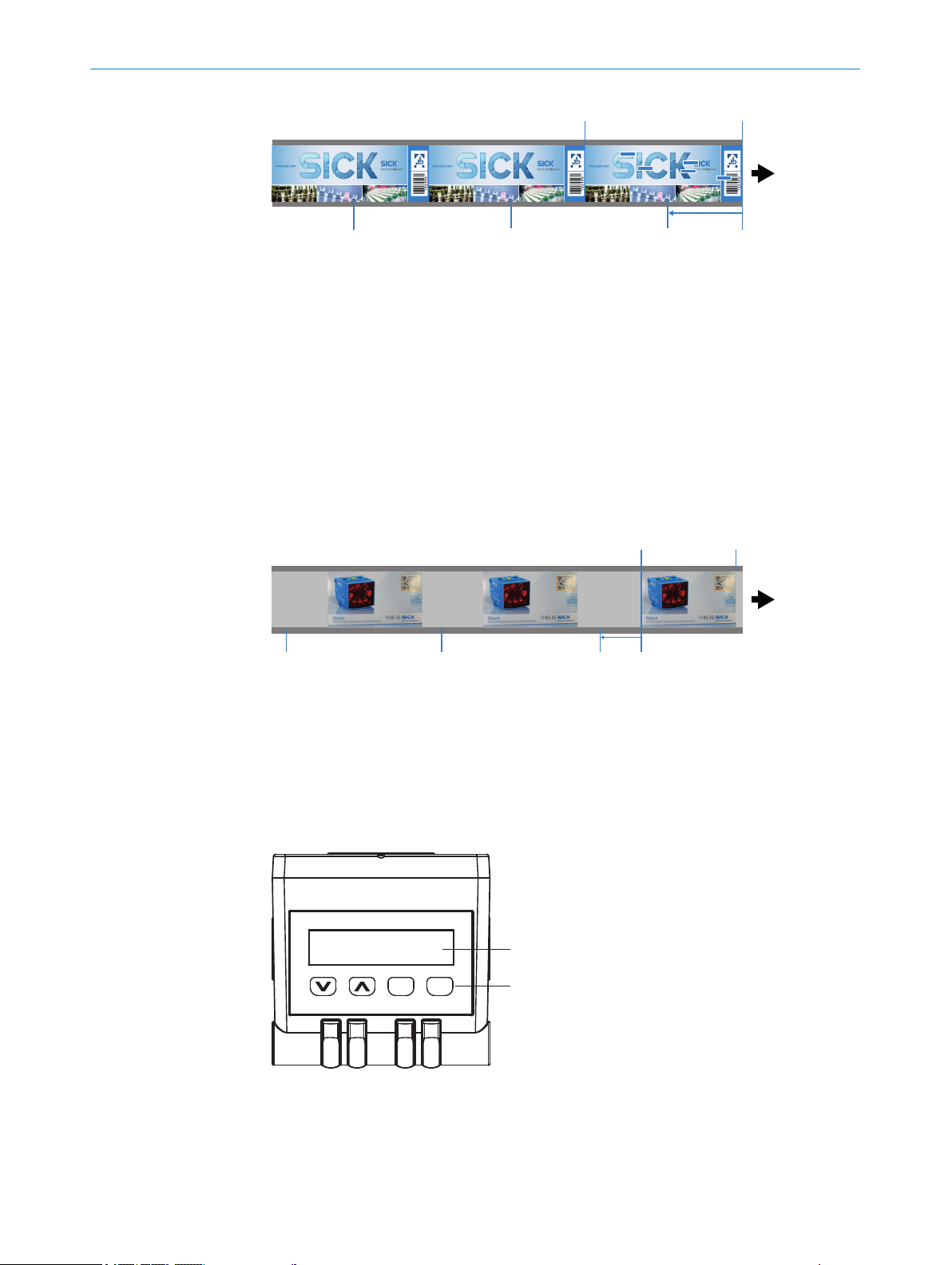
Figure 3: Recorded image from the perspective of the “PS30 pattern sensor”
Field of view
1
Light spot
2
Vertical bars: Cuts of the individual lines, corresponds to the encoder resolution.
Blue square marks: Clear and contrast-rich pattern areas automatically selected by the
sensor. Five areas have been selected in this example.
Function
The PS30 pattern sensor is an opto-electronic sensor that detects recurring patterns in
a contactless manner.
The principle of operation is based on a line camera which constantly searches for con‐
trast differences and sharp edges in the print image (see figure). These distinct and
unique areas in the pattern are automatically selected by the sensor during the teach-in
process. If the image and contrast pattern stay the same, these points will be in exactly
the same locations. The sensor evaluates grayscale information.
A taught-in image is used as a reference for the subsequent detection of a recurring
contrast pattern. The print marks usually used for determining position are no longer
necessary. When a pattern matching the reference pattern is identified, a switching out‐
put is initiated.
The PS30 pattern sensor requires for its operation information about the speed of the
material, e.g., from encoder pulses, from a motor feedback system, or as a defined vari‐
able with a fixed value or a value updated via TCP/IP.
3.3 Operating modes
The PS30 pattern sensor can be operated in one of two modes:
1 Endless material
2 Single object
3.3.1 Endless material operating mode
When further processing endless materials such as film and paper webs to produce, for
example, labels and packaging with a constant repeat length, exact determination of
position is essential, e.g., to determine the cut position.
12
Typically, the target cut position is selected as the start point of the reference image,
and the reference image is terminated before the end of the repeat length. The start
point of the teach-in area is the position of the switching signal. A switching point offset
can also be configured.
O PE R AT I NG IN S TR U CT I ON S | PS30 8018916.ZYN1/2018-05-17 | SICK
Subject to change without notice
Page 13
1 2
3
444
Figure 4: Recorded image from the perspective of the “PS30 pattern sensor”
1 2
3
444
1
356 4
EscSet
2
Teach Stop
1
Teach Start
2
Offset
3
Signal
4
3.3.2 Single object operating mode
In this case the position is to be determined for repeating, separate objects with identi‐
cal patterns but not separated by a fixed distance. An object, or a section of the object
is taught in as a reference.
The end of the teach-in area is used as the position for outputting the switching signal.
A switching point offset can be defined.
PRODUCT DESCRIPTION 3
Figure 5: Endless material operating mode
Teach Stop
1
Teach Start
2
Offset
3
Signal
4
3.4 Display and operating elements
Figure 6: Display and operating elements
1
2
3
Display
Pushbuttons
Function indicator (yellow) “Act”
8018916.ZYN1/2018-05-17 | SICK O P ER A TI N G I NS T RU C TI O NS | PS30
Subject to change without notice
13
Page 14

3 PRODUCT DESCRIPTION
4
5
6
Function indicators (LEDs)
Table 1: Function indicators (LEDs)
Function indicator Description
Act Data transfer display
Link Ethernet connection display
Q Switching output display
ON Operating status display
Function indicator (green) “Link”
Function indicator (yellow) “Q”
Function indicator (green) “ON”
Yellow LED: Data transfer
•
LED off: No data transfer
•
Green LED: Ethernet connection available
•
LED off: No Ethernet connection available
•
Yellow LED: Output high
•
LED off: Output low
•
LED flashing (10 Hz): Overcurrent/short-circuit protection
•
has triggered
Green LED: Normal operation/Supply voltage on
•
LED off: No operation
•
Symbols on the display
The following symbols may appear on the display: “RUN”, “MEN” and “SET”.
Table 2: Symbols on the display
Icon Description
RUN RUN symbol is lit up: The display shows the current operating data
of the sensor.
MEN MEN symbol is lit up: You are in the menu structure and have not
yet reached the last selection level.
SET SET symbol is lit up: Sensor settings can be changed and,
for example, values set.
Pushbuttons
Table 3: Pushbuttons
Pushbutton Description
Select operating menu, parameter, or option
•
Reduce value
•
Select operating menu, parameter, or option
•
Increase value
•
Short press:
•
•
Switch to the next-lowest menu level
°
Save parameter change
°
Confirm selection
°
Long press (> 2 sec.):
Start the operating menu
°
14
O PE R AT I NG IN S TR U CT I ON S | PS30 8018916.ZYN1/2018-05-17 | SICK
Subject to change without notice
Page 15
3.5 Display
EscSet
RUN
EscSet
Teach
MEN
EscSet
ErrCod
MEN
Pushbutton Description
Short press: Exit parameters without saving. Switch to the
•
next-highest menu level.
Long press: Exit parameters without saving. Change to the
•
default display - Quality of Run.
Default display
Figure 7: Default display
Operating menus - Monitoring/Setting/Teach-in/Info
PRODUCT DESCRIPTION 3
3.6 Bar graph
Figure 8: Operating menu
Parameters using example of monitoring
Figure 9: Parameter display
Teach-in quality
After teach-in has been run, the number of flashing bars indicates the quality of the
teach-in process:
If 3 or more bars are flashing: the teach-in process was successful.
•
If fewer than 3 bars are flashing: check whether the signal is switching correctly. If
•
the signal is not switching correctly, repeat the teach-in process.
Process quality
When the RUN symbol is lit up, the number of bars indicates the process quality.
If 2 or fewer bars are flashing: check whether the signal is switching correctly.
•
If the signal is not switching correctly, verify that the sensor is installed correctly,
•
and check the quality of the print image and the mechanical guiding of the object.
If necessary, repeat the teach-in process.
•
8018916.ZYN1/2018-05-17 | SICK O P ER A TI N G I NS T RU C TI O NS | PS30
Subject to change without notice
15
Page 16

4 TRANSPORT AND STORAGE
4 Transport and storage
4.1 Transport
For your own safety, please read and observe the following notes:
NOTE
Damage to the sensor due to improper transport.
■
The device must be packaged for transport with protection against shock and
damp.
■
Recommendation: Use the original packaging as it provides the best protection.
■
Transport should be performed by specialist staff only.
■
The utmost care and attention is required at all times during unloading and trans‐
portation on company premises.
■
Note the symbols on the packaging.
■
Do not remove packaging until immediately before you start mounting.
4.2
Transport inspection
4.3 Storage
Immediately upon receipt at the receiving work station, check the delivery for complete‐
ness and for any damage that may have occurred in transit. In the case of transit dam‐
age that is visible externally, proceed as follows:
■
Do not accept the delivery or only do so conditionally.
■
Note the scope of damage on the transport documents or on the transport com‐
pany’s delivery note.
■
File a complaint.
NOTE
Complaints regarding defects should be filed as soon as these are detected. Damage
claims are only valid before the applicable complaint deadlines.
Store the device under the following conditions:
■
Recommendation: Use the original packaging.
■
Do not store outdoors.
■
Store in a dry area that is protected from dust.
■
So that any residual damp can evaporate, do not package in airtight containers.
■
Do not expose to any aggressive substances.
■
Protect from sunlight.
■
Avoid mechanical shocks.
■
Storage temperature: see "Technical data", page 63.
■
Relative humidity: see "Technical data", page 63.
■
For storage periods of longer than 3 months, check the general condition of all
components and packaging on a regular basis.
16
O PE R AT I NG IN S TR U CT I ON S | PS30 8018916.ZYN1/2018-05-17 | SICK
Subject to change without notice
Page 17

5 Mounting
5.1 Scope of delivery
Included with delivery:
PS30 pattern sensor
•
Blind plug for M12 Ethernet connection
•
Adjustment tool
•
Optional: accessories, see "Accessories", page 66
•
Quickstart
•
5.2 Mounting requirements
Typical space requirement for the device, see type-specific dimensional drawing,
•
see "Technical data", page 63.
Comply with technical data, such as the permitted ambient conditions for opera‐
•
tion of the device (e.g., temperature range, EMC interference emissions, ground
potential),
To prevent condensation, avoid exposing the device to rapid changes in tempera‐
•
ture.
Protect the device from direct sunlight.
•
The device must only be mounted using the pairs of mounting threads/fixing holes
•
provided for this purpose.
Shock and vibration-free mounting.
•
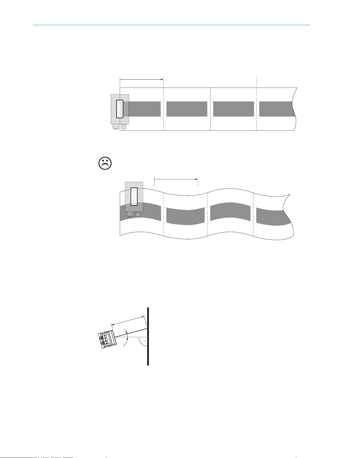
The light spot must cover a significant area on the print image. Select an area with
•
high contrast differences and unique pattern elements as the significant area. The
center of the light spot is marked with a notch on the upper side of the housing.
Sensing distance: 20 mm
•
The sensing distance is the distance from the front edge of the sensor (housing
edge) to the sensing target (e.g., an object).
MOUNTING 5
NOTE
We recommend using the supplied adjustment tool to align the pattern sensor.
8018916.ZYN1/2018-05-17 | SICK O P ER A TI N G I NS T RU C TI O NS | PS30
Subject to change without notice
17
Page 18
☺
1 2
1 2
3
α
1
5 MOUNTING
Significant areas
Figure 10: Align the light spot on the print image
Start (SET/ET)
1
Stop (SET/ET)
2
Q
3
The gray squares correspond to the print areas with unique features.
Arrangement when scanning on a flat surface or flat material
Figure 11: Arrangement of the pattern sensor when scanning on a flat surface or flat material
SD
1
α: 15° angle
SD: 20 mm sensing distance
18
O PE R AT I NG IN S TR U CT I ON S | PS30 8018916.ZYN1/2018-05-17 | SICK
Subject to change without notice
Page 19
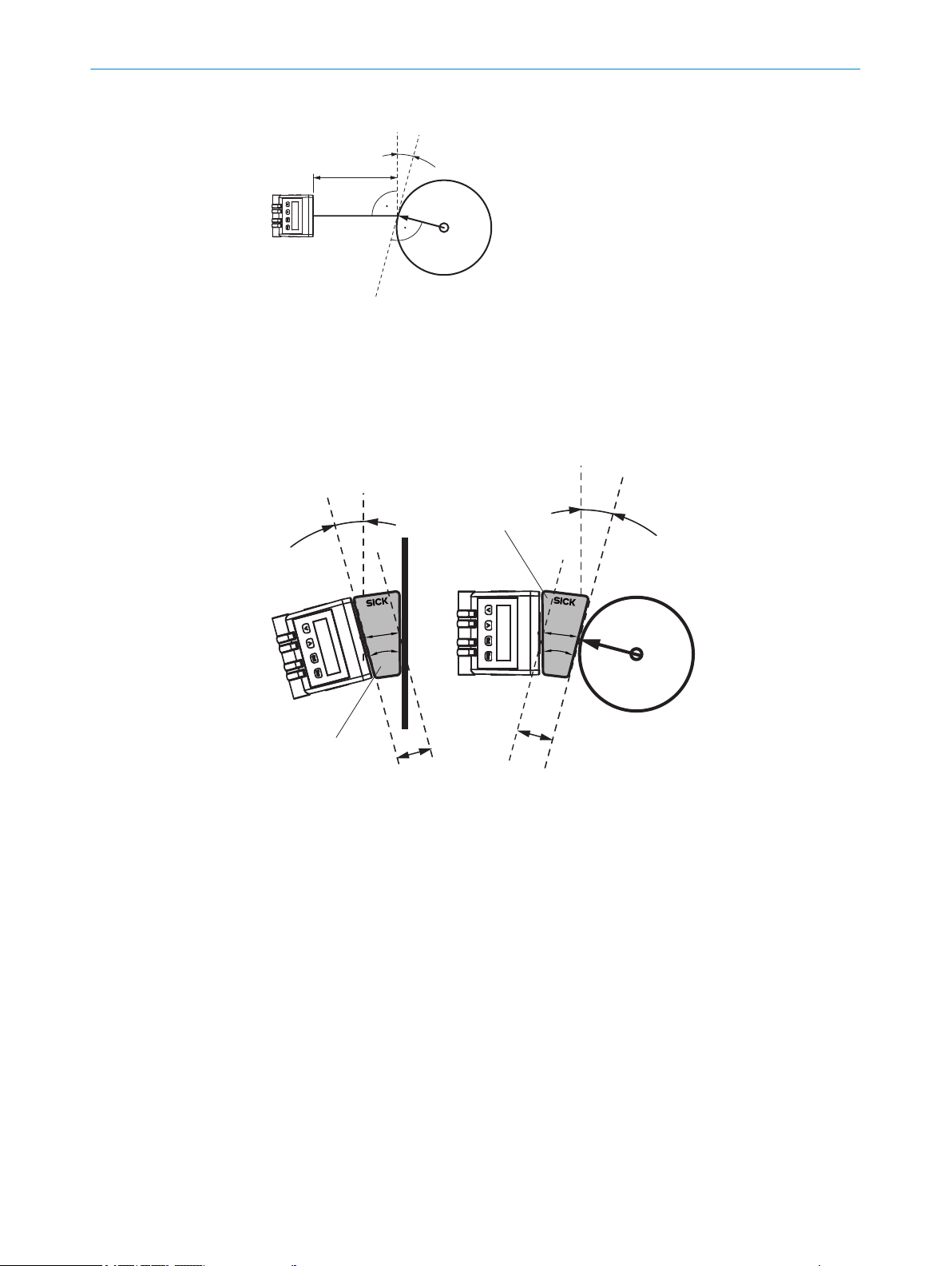
Arrangement when scanning rotary systems
α
1
α
α
1
1
2
3
2
3
4
4
Figure 12: Arrangement of the pattern sensor when scanning rotary systems
SD
1
α: 15° angle
SD: 20 mm sensing distance
Using the adjustment tool
MOUNTING 5
Figure 13: Using the adjustment tool
Adjustment tool
1
20 mm
2
15°
3
SD
4
5.3 Mounting the device
1. Select a mounting location for the pattern sensor (see "Mounting requirements",
page 17).
8018916.ZYN1/2018-05-17 | SICK O P ER A TI N G I NS T RU C TI O NS | PS30
Subject to change without notice
2. Mount the pattern sensor using the fixing holes (see "Technical data", page 63).
19
Page 20

6 ELECTRICAL INSTALLATION
6 Electrical installation
6.1 Notes on the electrical installation
NOTICE
Device damage due to incorrect supply voltage!
An incorrect supply voltage may result in damage to the device.
■
Only operate the device with safety/protective extra-low voltage (SELV/PELV).
■
The sensor is a device of protection class III.
NOTICE
Device damage due to incorrect supply voltage!
An incorrect supply voltage may result in damage to the device.
Only operate the device with an LPS (limited power source) in accordance with IEC
•
60950-1 or an NEC Class 2 power supply unit.
NOTICE
Device damage or unpredictable operation due to working with live parts!
Working with live parts may result in unpredictable operation.
■
Only carry out wiring work when the power is off.
■
Only connect and disconnect electrical connections when the power is off.
■
The electrical installation must only be performed by electrically qualified person‐
nel.
■
Standard safety requirements must be met when working on electrical systems!
■
Only switch on the supply voltage for the device when the connection tasks have
been completed and the wiring has been thoroughly checked.
■
When using extension cables with open ends, ensure that bare wire ends do not
come into contact with each other (risk of short-circuit when supply voltage is
switched on!). Wires must be appropriately insulated from each other.
■
Wire cross-sections in the supply cable from the user’s power system must be
selected in accordance with the applicable standards.
■
Only operate the device with an LPS (limited power source) in accordance with IEC
60950-1 or an NEC Class 2 power supply unit.
■
All circuits connected to the device must be designed as SELV/PELV circuits.
■
Operation in short-circuit protected network at max. 8 A.
NOTE
Layout of data cables
■
Use screened data cables with twisted-pair wires.
■
Implement the screening design correctly and completely.
■
To avoid interference, e.g., from switching power supplies, motors, clocked drives,
and contactors, always use cables and layouts that are suitable for EMC.
■
Do not lay cables over long distances in parallel with voltage supply cables and
motor cables in cable channels.
20
The IP enclosure rating for the device is only achieved under the following conditions:
■
The cables plugged into the connections are screwed tight.
■
Any other covers present must be closed and lie flush on the device.
If these instructions are not complied with, the IP enclosure rating for the device is not
guaranteed!
O PE R AT I NG IN S TR U CT I ON S | PS30 8018916.ZYN1/2018-05-17 | SICK
Subject to change without notice
Page 21

6.2 Wiring notes
ELECTRICAL INSTALLATION
NOTICE
Faults due to incorrect wiring!
Incorrect wiring may result in operational faults.
■
For data transmission, use only shielded cables with twisted-pair wires.
■
Follow the wiring notes precisely.
NOTE
Preassembled cables can be found online at:
www.sick.com/PS30
b
All electrical connections of the device are configured as M12 round connectors. The
enclosure rating is only achieved with screwed plug connectors or cover caps.
Please observe the following wiring notes:
■
A correct and complete cable shielding design is required for trouble-free data
transmission.
■
The cable shield must be connected at both ends in the control cabinet and at the
device. The cable shield of the pre-assembled cables is connected to the knurled
nut of the male/female connector and thus also to a large area of the device hous‐
ing.
■
The cable shield in the control cabinet must be connected to a large area of the
signal ground, see figure 17.
■
Appropriate measures must be taken to prevent equipotential bonding currents
flowing through the cable shield.
■
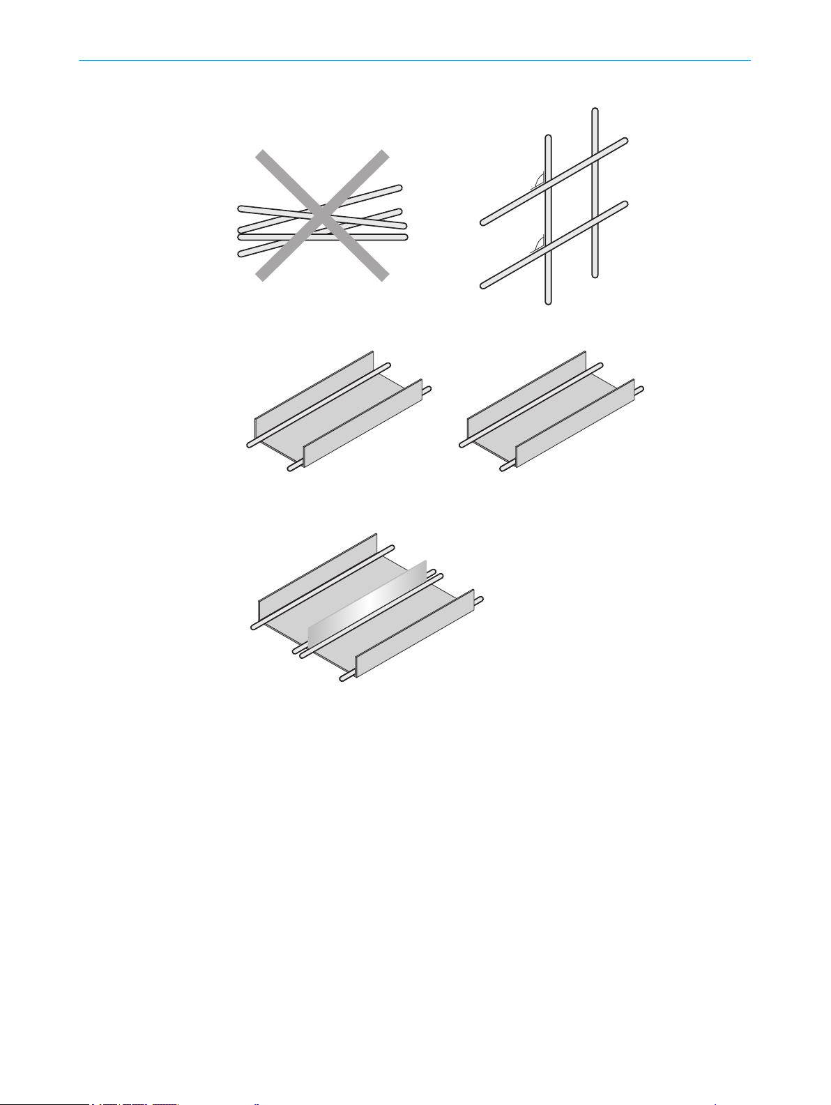
During installation, pay attention to the different cable groups. The cables are
grouped into the following four groups according to their sensitivity to interference
or radiated emissions:
6
Group 1: Cables very sensitive to interference, such as analog measuring
°
cables
Group 2: Cables sensitive to interference, such as sensor cables, communi‐
°
cation signals, bus signals
Group 3: Cables which are a source of interference, such as control cables
°
for inductive loads, motor brakes
Group 4: Cables which are powerful sources of interference, such as output
°
cables from frequency inverters, welding system power supplies, power
cables
w
Cables in groups 1, 2 and 3, 4 must be crossed at right angles, see figure 14.
w
Cables in groups 1, 2 and 3, 4 must be routed in different cable channels or
metallic separators must be used, see figure 15 and see figure 16. This
applies particularly where cables of devices with a high level of radiated emis‐
sion, such as frequency converters, are laid parallel to sensor cables.
8018916.ZYN1/2018-05-17 | SICK O P ER A TI N G I NS T RU C TI O NS | PS30
Subject to change without notice
21
Page 22
1
2
4
3
1
2
4
3
90
90
1
2
3
4
1
2
3
4
ELECTRICAL INSTALLATION
6
Figure 14: Cross cables at right angles
Figure 15: Ideal laying – Place cables in different cable channels
Figure 16: Alternative laying – Separate cables with metallic separators
22
O PE R AT I NG IN S TR U CT I ON S | PS30 8018916.ZYN1/2018-05-17 | SICK
Subject to change without notice
Page 23
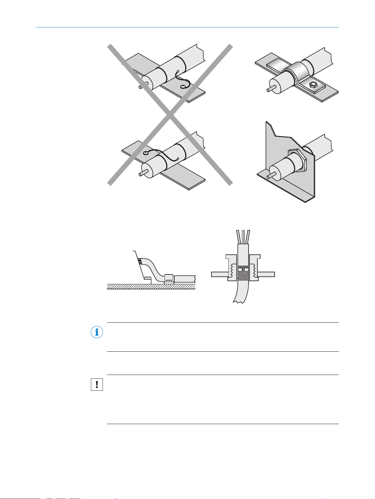
ELECTRICAL INSTALLATION 6
Figure 17: Make an extensive and low-impedance ground connection of the cable shield in the
control cabinet
Figure 18: Shield connection in plastic housings
NOTE
Prevent equipotential bonding currents via the cable shield with a suitable grounding
concept.
6.3 Note on the swivel connector
NOTICE
Damage to the connector unit from over-tightening!
The connector unit on the device has two opposite end positions.
■
Do not rotate the connector unit from either of the two end positions by more than
180°.
8018916.ZYN1/2018-05-17 | SICK O P ER A TI N G I NS T RU C TI O NS | PS30
Subject to change without notice
23
Page 24

1
2
3
4 5
6
7
8
9
6 ELECTRICAL INSTALLATION
6.4 System configuration
The integration of the PS30 pattern sensor into the machine controller is shown in the
following figure. The information on the movement of the material does not necessarily
need to be provided by an encoder, the signal can of course also be created by a motor
feedback system or the controller.
Alternatively, the speed of the material can be stored as a constant. This alternative is
intended for applications with a constant or only slowly changing material speed.
The connection to an operating terminal is not essential, but is recommended to allow
the visually-supported operation and diagnostic features to be used. If no connection to
the HMI is provided, e.g., the device is operated via the display and operating elements
on the pattern sensor itself, a PC can, where necessary, be connected via Ethernet for
commissioning and/or service work, and to utilize the SOPASair configuration tool pro‐
vided on the web server.
Figure 19: Example system configuration
PC
1
SOPASair
2
Ethernet TCP/IP
3
OPC DA, JSON API
4
HMI
5
PLC
6
Function blocks
7
TTL/HTL
8
A machine cycle as the input signal, e.g., via an encoder or a motor feedback system
9
6.5 Connecting the device electrically
DANGER
Pre-assembled cables see "Technical data", page 63.
1. Ensure the voltage supply is not connected.
2. If necessary, turn the swivel connector into the desired position as shown in the
figure.
24
O PE R AT I NG IN S TR U CT I ON S | PS30 8018916.ZYN1/2018-05-17 | SICK
Subject to change without notice
Page 25

1
2
Figure 20: Rotate the swivel connector, establish the electrical connection
M12 (A-coded)
FE (shield)
L+
M
AT
1
2
brn
blu
3
wht
5
pnk
Enc B
4
grn
Enc ¯B
6
yel
Q
OUT
7
blk
nc
9
red
Status
OUT
10
vio
Enc A
11
gra/pnk
Enc ¯A
12
red/blu
ET
8
gra
1
nc
1
2
3
11
4
5
6
7
8
9
1
10
12
Supply voltage, external teach-in signal and, if applicable, encoder signal and switch‐
1
ing output
Ethernet
2
3. Connect the device according to the connection diagram.
6.6 Pin assignment of the connections
6.6.1 Pin assignment for supply voltage and encoder signals
ELECTRICAL INSTALLATION 6
Figure 22: Male connector, M12, 12-pin, Acoded
Figure 21: Connection diagram for supply volt‐
age, external teach-in signal, encoder signal and
switching output
nc: not connected
1
Table 4: Description of supply voltage male connector, external teach-in signal, encoder signal
and switching output
8018916.ZYN1/2018-05-17 | SICK O P ER A TI N G I NS T RU C TI O NS | PS30
Subject to change without notice
Pin Marking Wire color Description
1 L+ Brown Supply voltage: +12 … +30 V DC
2 M Blue Supply voltage: 0 V
3 nc White Not assigned (spare)
4 Enc B Green Encoder signal B
5 AT Pink Blanking input
6 Enc B(overline) Yellow Encoder signal B’
7 Q
OUT
Black Switching output (see "Technical
data", page 63)
8 ET Gray External teach-in signal
25
Page 26

Tx+
Rx+
Tx–
Rx–
1
2
4
wht/grn
ora
wht/ora
grn
3
M12 (D-coded)
3
2
4
1
6 ELECTRICAL INSTALLATION
Pin Marking Wire color Description
9 nc Red Not assigned (spare)
10 Status
11 Enc A Gray/pink Encoder signal A
12 Enc Ā Red/blue Encoder signal A’
6.6.2 Pin assignment for Ethernet
The pattern sensor is equipped with a 100Base-T Ethernet connection.
Figure 23: Ethernet connection diagram
Table 5: Ethernet female connector description
Pin Marking Wire color Description
1 Tx+ White/orange Send data signal, not inverted
2 Rx+ White/green Receive data signal, not
3 Tx- Orange Send data signal, inverted
4 Rx- Green Receive data signal, inverted
OUT
Violet Sensor status (see "Technical
data", page 63)
Figure 24: Female connector, M12, 4-pin, Dcoded
inverted
26
O PE R AT I NG IN S TR U CT I ON S | PS30 8018916.ZYN1/2018-05-17 | SICK
Subject to change without notice
Page 27

7 Commissioning
7.1 Pushbutton damage
NOTICE
Pushbutton damage due to improper handling
Improper handling of the pushbuttons can damage them. This will make operation diffi‐
cult or impossible.
For this reason:
Only operate the pushbuttons with your fingers or a suitable pointing device.
•
Do not operate the pushbuttons using sharp or hard objects.
•
7.2 Steps to take
1. Switch on the supply voltage. “RUN” appears on the display during initial commis‐
sioning. In this case, press the SET pushbutton for at least 2 seconds. “Setup”
appears on the display.
2. Set the parameters for the encoder (see "Setting up the encoder", page 27).
3. Select “Endless material” or “Single object” operating mode (see "Operating
modes", page 12).
4. If necessary, change the resolution (see "Settings menu", page 33).
5. Run the teach-in process and, if necessary, set identical areas for blanking.
You can choose between the following options for the teach-in process:
°
°
°
°
You can choose between the following options for blanking:
°
°
°
6. If necessary, set an offset for adjustment of the switching point:
°
°
COMMISSIONING 7
Manual start-length teach-in via the “Teach” menu, see "Teach menu",
page 37
Start-stop teach-in via an external teach-in signal, see "Executing start-stop
teach-in via an external teach-in signal", page 34
Start-length teach-in via an external teach-in signal, see "Executing start-
length teach-in via an external teach-in signal", page 35
Start-length teach-in via SOPASair or Ethernet , see "Integrating the PS30 pat‐
tern sensor in the network", page 45
Blanking via the “Blank” parameter in the Teach menu of the control panel
see "Blanking areas (Blank) parameter", page 40
Blanking via the AT input, see "Specifying image areas via an “AT” external
signal", page 42
Blanking via SOPASair or Ethernet, see "Teach-in menu", page 46
via the “Offset” menu item in the Teach menu of the control panel see
"Switching point offset (OffSet) parameter", page 39
via SOPASair or Ethernet, see "Teach-in menu", page 46
NOTE
Teach-in via an external signal always has priority over the other teach-in methods.
7.3 Setting up the encoder
NOTE
The encoder resolution (EncRes) must be between 100 μm ... 600 μm. If necessary,
use a configurable encoder. Provided the above encoder resolution range is adhered to,
you can also use an existing motor feedback system.
8018916.ZYN1/2018-05-17 | SICK O P ER A TI N G I NS T RU C TI O NS | PS30
Subject to change without notice
27
Page 28

1
2
3
4
COMMISSIONING
7
Menu structure
For details of the menu structure, see "Menu structure", page 69.
Encoder settings
“Setup” is shown on the display during initial commissioning. During this setup, the
device will prompt for the settings of the encoder used. The following parameters must
be entered for the encoder:
“EncTyp” (encoder type)
•
“EncRes” (encoder resolution) → See the following section on calculating the
•
encoder resolution
“EncDir” (encoder direction)
•
If you are not using an encoder, accept the factory settings for these parameters. Fur‐
ther settings can be configured in SOPASair (see "Operation via SOPASair", page 45).
NOTE
To ensure a correct signal, the rotational direction during the teach-in process must
match the configured encoder direction.
Calculating the encoder resolution
Figure 25: Calculating the encoder resolution
U
1
S
2
n
3
Encoder
4
The graphic is provided as an example for the purposes of illustrating the encoder reso‐
lution. The roller geometry is not essential. The encoder resolution is the path covered
by the material from encoder bar to encoder bar.
The encoder resolution (EncRes) can be calculated using the following formula:
S = U/n
S: Encoder resolution
U = External circumference of the roller
n: Number of encoder bars in 360°
28
O PE R AT I NG IN S TR U CT I ON S | PS30 8018916.ZYN1/2018-05-17 | SICK
Subject to change without notice
Page 29

Setup menu encoder settings
Table 6: Setup menu encoder settings
Display Description
EncTyp Select the encoder type.
Options
TTL: 4.5 V ... 5.5 V, TTL / RS-422 (differential)
•
HTL: 12 V ... 30 V, HTL / push-pull
•
Factory setting
TTL
•
EncRes Set the encoder resolution.
Adjustment range
100 μm ... 600 μm (in 1 μm increments)
•
Factory setting
100 μm
•
EncDir Select the encoder direction.
Options
Auto: the direction is determined automatically at the beginning
•
of the teach-in process
CW: clockwise
•
CCW: counter-clockwise
•
Factory setting
Auto
•
COMMISSIONING 7
Figure 26: Clockwise direction of rotation Figure 27: Counter-clockwise direction of rota‐
tion
Running the Setup menu
“Setup” appears on the display.
1. Press the SET pushbutton. The “EncTyp” (encoder type) parameter is displayed.
2. Press the SET pushbutton. The current value is displayed.
3. Select the encode type using the arrow pushbuttons.
4. Press the SET pushbutton; the “EncRes” (encoder resolution) parameter is dis‐
played. The first digit on the left flashes.
5. Press the up arrow pushbutton to increase the digit. Press the down arrow push‐
button to decrease the digit.
6. Press the SET pushbutton. The next digit flashes.
7. Repeat steps 5 and 6 until the last digit has been set. The “EncDir” (encoder direc‐
tion) parameter is displayed.
8. Select the encoder direction using the arrow pushbuttons.
9. Press the SET pushbutton. The prompt “Store?” is displayed.
10. Perform one of the following steps:
Press the SET pushbutton to save all inputs for the encoder. The Monitor
°
menu is displayed.
Press the ESC pushbutton to cancel the process.
°
8018916.ZYN1/2018-05-17 | SICK O P ER A TI N G I NS T RU C TI O NS | PS30
Subject to change without notice
29
Page 30

Setup
EncTyp
EncRes
…
…
EncDir …
Store? Settng
1
2
3
1
2
COMMISSIONING
7
Figure 28: Setup during initial commissioning
Default setting: TTL
1
Range: TTL/ HTL
Description: The encoder type must be specified.
Default setting: 100 µm
2
Range: 100 μm ... 600 μm in 1 μm increments
Description: The encoder resolution must be specified.
Default setting: Auto
3
Range: Auto/ CW/ CCW
Description: The direction of rotation of the encoder must be specified.
NOTE
The encoder settings are retained even after a reset. You can change the encoder set‐
tings later in the “Setting” menu.
7.4 Operation without encoder or machine cycle
If no external encoder will be used, the speed can be stored as a constant via
SOPASair. For general information on using SOPASair, see "Operation via SOPASair",
page 45.
To store the speed of the material as a constant, open the following page in your web
browser: 192.168.100.100/velocity.
If the IP address of the sensor was changed, insert that value (in place of
192.168.100.100).
30
Figure 29: Appearance of the display when not using an encoder
Using an external encoder
1
Speed in mm/s
2
Proceed as follows:
O PE R AT I NG IN S TR U CT I ON S | PS30 8018916.ZYN1/2018-05-17 | SICK
Subject to change without notice
Page 31

COMMISSIONING 7
1. Deselect the checkbox.
2. Enter the material speed in mm/s.
Save the settings using “save changes”.
The PS30 will now use the stored speed.
The specified speed is stored in the udiEncEmulationVelocity variable. This can be
changed dynamically via TCP/IP. Any changes in speed can therefore be taken into con‐
sideration. For real-time conditions, we recommend using an encoder signal or machine
cycle.
For a detailed description of the Ethernet interface and information about
udiEncEmulationVelocity, see www.sick.com/PS30.
8018916.ZYN1/2018-05-17 | SICK O P ER A TI N G I NS T RU C TI O NS | PS30
Subject to change without notice
31
Page 32

8 OPERATION
8 Operation
8.1 Pushbutton damage
NOTICE
Pushbutton damage due to improper handling
Improper handling of the pushbuttons can damage them. This will make operation diffi‐
cult or impossible.
For this reason:
Only operate the pushbuttons with your fingers or a suitable pointing device.
•
Do not operate the pushbuttons using sharp or hard objects.
•
8.2 Navigation
You can select a menu, parameter, option or value using the SET pushbutton and the
arrow pushbuttons. The menu path is specified in the relevant chapters of these
instructions.
For the overall menu structure and navigation (see "Menu structure", page 69).
8.3 Selecting an option
1. Select the desired parameter using the SET pushbutton and the arrow pushbut‐
tons.
2. Select the desired option using the arrow pushbuttons.
3. Perform one of the following steps:
°
°
4. Perform one of the following steps to return to the default display: Quality of Run:
°
°
8.4 Changing the value
1. Select the desired parameter using the SET pushbutton and the arrow pushbut‐
tons.
2. Press the SET pushbutton. The current value of the parameter is displayed. The
first digit on the left flashes.
3. Press the up arrow pushbutton to increase the digit. Press the down arrow push‐
button to decrease the digit.
4. Press the SET pushbutton to save the digit entered. The next digit flashes.
Press the ESC pushbutton to cancel the process.
5. Repeat steps 3 and 4 until the last digit is saved. The parameter name is dis‐
played.
6. Press the SET pushbutton repeatedly until the Quality of Run default display is
shown again. Alternatively, you can wait for approx. one minute. The display will
automatically switch back to the default display if no pushbuttons are pressed.
Press the SET pushbutton to save the change.
Press the ESC pushbutton to cancel the process. The parameter name is dis‐
played again.
Press the SET pushbutton repeatedly until the status display is displayed
again.
Wait for approx. one minute. The display will automatically switch back to the
status display if no buttons are pressed. Any settings you have made will also
be saved.
32
O PE R AT I NG IN S TR U CT I ON S | PS30 8018916.ZYN1/2018-05-17 | SICK
Subject to change without notice
Page 33

8.5 Settings menu
OPERATION 8
The Settings menu – displayed as
ration parameters listed below.
To access the parameters in the Settings menu, press SET then select the parameter
using the arrow pushbuttons.
The available options are selected by pressing SET followed by the arrow pushbuttons,
and confirmed by pressing SET.
8.5.1 Operating mode (Mode) parameter
Table 7: Operating mode (Mode) parameter
Parameter Description
Endl Endless material operating mode
Single Single object operating mode
Factory setting: Endl – Endless material
8.5.2 Encode type (EncTyp) parameter
Table 8: Encode type (EncTyp) parameter
Parameter Description
EncTyp Select the encoder type.
Settng – is used to configure the sensor configu‐
MEN
A web with recurring, connected patterns is moved past the pat‐
tern sensor. The switching point corresponds to the start of the
teach-in area. An offset can be used to shift the switching point.
Single, non-connected objects are moved past the pattern sensor.
The switching point corresponds to the end of the taught-in object
area. An offset can be used to shift the switching point.
Options
TTL: 4.5 V ... 5.5 V, TTL / RS-422 (differential)
•
HTL: 12 V ... 30 V, HTL / push-pull
•
Factory setting
TTL
•
8.5.3 Encode resolution (EncRes) parameter
Table 9: Encode resolution (EncRes) parameter
Parameter Description
EncRes Set the encoder resolution
Adjustment range
100 ... 600 μm (in 1 μm increments)
•
Factory setting
100 μm
•
8018916.ZYN1/2018-05-17 | SICK O P ER A TI N G I NS T RU C TI O NS | PS30
Subject to change without notice
33
Page 34

OPERATION
8
8.5.4 Encoder direction (EncDir) parameter
Table 10: Encoder direction (EncDir) parameter
Parameter Description
EncDir Select the encoder direction
8.5.5 External teach-in (ETeach) parameter
Table 11: External teach-in (ETeach) parameter
Option Description
Start-stop teach-in (StaSto) The rising signal edge at the input starts the teach-in process, the
Start-length teach-in
(StaLen)
Options
Auto:
•
CW: clockwise
•
CCW: counter-clockwise
•
Factory setting
Auto
•
falling signal edge ends the teach-in process. About teach-in: see
"Executing start-stop teach-in via an external teach-in signal",
page 34
The rising signal edge at the input starts the teach-in process. The
teach-in process is automatically ended by the sensor after the
teach-in length entered as a parameter is reached. About teach-in:
see "Executing start-length teach-in via an external teach-in sig‐
nal", page 35
Factory setting: StaSto – Start-stop teach-in
8.5.5.1 Executing start-stop teach-in via an external teach-in signal
Prerequisite: The encoder settings, the operating mode, and the resolution have been
configured.
1. Press and hold the SET pushbutton for at least 2 seconds to access the “Monitr”
menu.
2. Select the “StaSto” option.
Menu path: Status display → SET→ Monitr → Arrow pushbuttons → Setting → SET →
Mode → Arrow pushbuttons → ETeach → SET → StaSto
3. Position the light spot at a significant point on the print image. This point later
becomes the start point. When using the Endless material operating mode, the
start point corresponds to the switching point.
4. Apply an external voltage signal to the “ET” input. The teach-in process starts. The
current point is saved as the start point.
5. Pass a maximum of one object length/format length through the light spot in the
rotational direction of the encoder with positional accuracy. Note that to ensure a
correct signal, the rotational direction during the teach-in process must match the
configured encoder direction (EncDir).
6. Remove the external voltage signal from the “ET” input. The current point is saved
as the end point. The stop point is the switching point when in Single object oper‐
ating mode. The teach-in process ends. The display shows the message “Busy”.
7. When using the Endless material operating mode, continue moving formats
through the light spot until the message “Busy” disappears. When using the Single
object operating mode, no further objects are required. The calculation of the
teach-in image and the reference areas is performed while the message “Busy” is
displayed. Once the teach-in process is complete, the quality of the teach-in
process is displayed as a bar graph:
34
O PE R AT I NG IN S TR U CT I ON S | PS30 8018916.ZYN1/2018-05-17 | SICK
Subject to change without notice
Page 35

If 3 or more bars are flashing: the teach-in process was successful.
°
If fewer than 3 bars are flashing: check whether the signal is switching cor‐
°
rectly. If the signal is not switching correctly, the teach-in process must be
repeated.
8. The bar graph flashes for another 10 format lengths, then the display automati‐
cally changes to the “Quality of Run” status display. The bar graph indicating the
process quality no longer flashes. The RUN symbol is displayed.
Requirements
Note the “Minimum format length”, “Maximum format length” and “Minimum for‐
•
mat height” technical data, see "Technical data", page 63.
The light spot must cover a significant area on the print image. Select an area with
•
high contrast differences and unique features as the significant area, see "Mount‐
ing requirements", page 17.
The sensing distance (distance from the front edge of the sensor to the object)
•
and the angle of the pattern sensor to the image must be adhered to, see "Mount‐
ing requirements", page 17.
Avoid fluctuations in distance and height.
•
Teach in a maximum of a complete format length/object length.
•
8.5.5.2 Executing start-length teach-in via an external teach-in signal
OPERATION
8
Prerequisite: The encoder settings, the operating mode, and the resolution have been
configured.
1. Press and hold the SET pushbutton for at least 2 seconds to access the “Monitr”
menu.
2. Select the “StaLen” option.
Menu path: Status display → SET→ Monitr → Arrow pushbuttons → Setting → SET →
Mode → Arrow pushbuttons → ETeach → SET → StaSto →Arrow pushbuttons →
StaLen
3. Press the SET pushbutton. The currently entered object length/format length is
displayed.
4. Press the SET pushbutton. The first digit on the left flashes.
5. If necessary, change the value, see "Changing the value", page 32.
6. Position the light spot at a significant point on the print image. This point later
becomes the start point. When using the Endless material operating mode, the
start point corresponds to the switching point.
7. Apply an external voltage pulse to the “ET” input. The teach-in process starts at
the rising signal edge. The current point is saved as the start point.
8. Pass the format or object through the light spot in the rotational direction of the
encoder with positional accuracy. Note that to ensure a correct signal, the rota‐
tional direction during the teach-in process must match the configured encoder
direction (EncDir).
9. After the entered teach-in length has run through, the teach-in process stops auto‐
matically. When using the Single object operating mode, the end point of the
teach-in process corresponds to the switching point.
10. When using the Endless material operating mode, continue moving formats
through the light spot until the message “Busy” disappears. When using the Single
object operating mode, no further objects are required. The calculation of the
teach-in image and the reference areas is performed while the message “Busy” is
displayed. The quality of the teach-in process is shown as a bar graph on the dis‐
play:
If 3 or more bars are flashing: the teach-in process was successful.
°
If fewer than 3 bars are flashing: check whether the signal is switching cor‐
°
rectly. If the signal is not switching correctly, the teach-in process must be
repeated.
8018916.ZYN1/2018-05-17 | SICK O P ER A TI N G I NS T RU C TI O NS | PS30
Subject to change without notice
35
Page 36

8 OPERATION
11. The bar graph flashes for another 10 format lengths, then the display automati‐
cally changes to the “Quality of Run” status display. The bar graph indicating the
process quality no longer flashes. The RUN mode is displayed.
Requirements
Note the “Minimum format length”, “Maximum format length” and “Minimum for‐
•
mat height” technical data, see "Technical data", page 63.
The light spot must cover a significant area on the print image. Select an area with
•
high contrast differences and unique features as the significant area, see "Mount‐
ing requirements", page 17.
The sensing distance (distance from the front edge of the sensor to the object)
•
and the angle of the pattern sensor to the image must be adhered to, see "Mount‐
ing requirements", page 17.
Avoid fluctuations in distance and height.
•
Teach in a maximum of one format length/object length.
•
8.5.6 Ethernet configuration (Ethern) parameter
NOTE
Changes to the “Ethern” parameter are not adopted until the device is restarted.
Set the Ethernet configuration using the “Ethern” parameter.
For more information about the Ethernet interface, see "Operation via SOPASair",
page 45.
For the menu structure and navigation, see see "Menu structure", page 69.
Table 12: Ethern parameter
Parameter Description
IPAdr Enter an IP address.
Factory setting
MSB: 192
•
Byte 2: 168
•
Byte 1: 100
•
LSB: 100
•
SubMas Enter IP network mask.
Factory setting
MSB: 255
•
Byte 2: 255
•
Byte 1: 255
•
LSB: 0
•
D gate Enter default gateway.
Factory setting
MSB: 0
•
Byte 2: 0
•
Byte 1: 0
•
LSB: 0
•
Table 13: “Ethern” parameter - default values
Parameter Description
DHCP Factory setting: Deactivated.
MAC ID Individual address
36
O PE R AT I NG IN S TR U CT I ON S | PS30 8018916.ZYN1/2018-05-17 | SICK
Subject to change without notice
Page 37

Entering IPAdr, SubMas, DHCP, MAC ID and D gate
The “IPAdr”, “SubMas” and “D gate” parameters are entered in an identical manner.
Entry for the IP address is described here.
1. Select the “IPAdr” parameter under “Ethern”.
2. Press the SET pushbutton. The current value for the “Most significant byte” is dis‐
played. The first digit on the left flashes.
3. Press the up arrow pushbutton to increase the digit. Press the down arrow push‐
button to decrease the digit.
4. Press the SET pushbutton to save the digit entered. The next digit flashes.
5. Repeat steps 3 and 4 until the last digit is saved. The value of the next byte is dis‐
played.
6. Repeat steps 3 to 5 for the second, third and fourth byte (least significant byte).
7. After you have set the value of the fourth byte by pressing the SET pushbutton, the
“IPAdr” parameter is displayed.
8.5.7 Device reset (Reset) parameter
Performing a reset
Table 14: Device reset (Reset) parameter
Parameter Description
Reset Perform a reset.
Options
Yes: Perform a reset.
•
No
•
Factory setting
No
•
OPERATION 8
1. Select the “Reset” parameter in the “Settng” menu (see "Settings menu",
page 33).
2. Press the SET pushbutton.
3. Select the “yes” option.
4. Press the SET pushbutton to reset the device to its initial state. Press the ESC
pushbutton to cancel the process.
8.6 Teach menu
The Teach menu – displayed as
teach-in via the control panel. It can also be used to configure a switching point offset
and blanking areas for manual and external teach-in.
To access the parameters in the Teach menu, press SET then select the parameter
using the arrow pushbuttons.
The available options are selected by pressing SET followed by the arrow pushbuttons,
and confirmed by pressing SET.
8.6.1 Manual start-length teach-in via the control panel (StaLen) parameter
Requirements
Note the “Minimum format length”, “Maximum format length” and “Minimum for‐
•
mat height” technical data (see "Technical data", page 63).
The light spot must cover a significant area on the print image. Select an area with
•
high contrast differences and unique features as the significant area (see "Mount‐
ing requirements", page 17).
Teach – is used to execute the manual start-length
MEN
8018916.ZYN1/2018-05-17 | SICK O P ER A TI N G I NS T RU C TI O NS | PS30
Subject to change without notice
37
Page 38

OPERATION
8
The sensing distance (distance from the front edge of the sensor to the object)
•
and the angle of the pattern sensor to the image must be adhered to (see "Mount‐
ing requirements", page 17).
Avoid fluctuations in distance and height.
•
Teach in a maximum of one format length or object length.
•
StaLen parameter
Table 15: StaLen parameter
Value / option Description
Length Enter the length of the teach-in area in mm. Use a maximum of
the format length or object length as the teach-in length.
Currently entered format
length
START? Set the start point for the teach-in process.
Busy When using the Single object operating mode, move one object
Displays the currently entered length of the teach-in area. Confirm
or change the current length of the teach-in area.
Input range
15 mm ... 1,000 mm
•
Factory setting
240 mm
•
past the sensor; no further objects are required for the teach-in.
When using the Endless material operating mode, continue mov‐
ing patterns through the light spot until the message “Busy” disap‐
pears.
Performing start-length teach-in
Prerequisite: The encoder settings, the operating mode, and the resolution have been
configured.
1. Press and hold the SET pushbutton for at least 2 seconds to access the “Monitr”
menu.
2. Select the “StaLen” parameter.
Menu path: Status display→ SET→ Monitr → Arrow pushbuttons → Teach → SET →
StaLen
3. Press the SET pushbutton. The currently entered format length is displayed.
4. Press the SET pushbutton. The first digit on the left flashes.
5. If necessary, change the value, see "Changing the value", page 32.
6. Repeat step 5 until the last digit is saved. The “Start?” parameter is displayed.
7. Position the light spot at a significant point on the print image. This point later
becomes the start point. When using the Endless material operating mode, the
start point corresponds to the switching point.
8. Press the SET pushbutton. The point is saved as the start point. The display shows
the message “Busy”.
9. When using the Single object operating mode, move the object past the sensor.
The stop point of the teach-in process corresponds to the switching point in Single
object operating mode.
When using the Endless material operating mode, continue moving formats
through the light spot until the message “Busy” disappears. The quality of the
teach-in process is shown as a bar graph on the display:
If 3 or more bars are flashing: the teach-in process was successful.
°
If fewer than 3 bars are flashing: check whether the signal is switching cor‐
°
rectly. If the signal is not switching correctly, the teach-in process must be
repeated, see "Manual start-length teach-in via the control panel (StaLen)
parameter", page 37.
38
O PE R AT I NG IN S TR U CT I ON S | PS30 8018916.ZYN1/2018-05-17 | SICK
Subject to change without notice
Page 39

10. The bar graph flashes for another 10 format lengths, then the display automati‐
1 2
3
1 2
3
cally changes to the “Quality of Run” status display. The bar graph indicating the
process quality no longer flashes. The RUN symbol is displayed.
8.6.2 Switching point offset (OffSet) parameter
NOTE
If an offset is required, it must be entered after the areas to be blanked are set.
The offset is reset to 0 mm after every new teach-in.
OPERATION 8
Figure 30: Setting the offset (switching point shift) for Endless material operating mode
Teach Stop
1
Teach Start
2
Offset
3
Figure 31: Setting the offset (switching point shift) for Single object operating mode
Teach Stop
1
Teach Start
2
Offset
3
Offset parameter
You can shift the switching point for the “Q” switching output using the Offset parame‐
ter.
For the menu structure and navigation, see "Menu structure", page 69.
8018916.ZYN1/2018-05-17 | SICK O P ER A TI N G I NS T RU C TI O NS | PS30
Subject to change without notice
39
Page 40

www.sick.com
1 32
8 OPERATION
Table 16: Offset parameter
Parameter Description
Offset Shifts the switching point for the “Q” switching output to the
desired position. In Endless material operating mode, the start
point of the teach-in process is used as the switching point; in Sin‐
gle object operating mode, the stop point of the teach-in process
is used as the switching point.
Adjustment range
0 mm … taught-in format length in mm
•
Factory setting
0 mm
•
Setting the offset
Prerequisite: The encoder settings, the operating mode, and the resolution have been
configured.
1. Press and hold the SET pushbutton for at least 2 seconds to access the “Monitr”
menu.
2. Select the “Offset” parameter.
Menu path: Status display → SET→ Monitr → Arrow pushbuttons → Teach → SET →
StaLen→ Arrow pushbuttons → Offset
3. Press the SET pushbutton. The currently entered offset is displayed.
4. Press the SET pushbutton. The first digit on the left flashes.
5. If necessary, change the value, see "Changing the value", page 32.
6. Repeat step 5 until the last digit is saved.
7. Press the SET pushbutton. The point is saved as the start point.
8.6.3 Blanking areas (Blank) parameter
NOTE
Blanking of image areas can only be performed after a successful teach-in process. The
blanking areas are deactivated again after each new teach-in process.
The teach-in quality can change due to the use of blanking areas.
Figure 32: Blanking out image areas
Start value for blanking
1
Blanking area
2
End value for blanking
3
You can use the “Blank” parameter to blank identical image areas (see "Menu struc‐
ture", page 69).
40
O PE R AT I NG IN S TR U CT I ON S | PS30 8018916.ZYN1/2018-05-17 | SICK
Subject to change without notice
Page 41

OPERATION 8
Table 17: “Blank” parameter
Parameter / option Description
Area1 Enter the first area for blanking. An upper and lower limit must be
entered for each area.
Adjustment range
0 ... 999 mm
•
Area2 Select the second area for blanking.
Adjustment range
0 ... 999 mm
•
Area3 Press the SET pushbutton to start the blanking process.
Entering blanking areas
In Endless material operating mode you can configure two areas for blanking in the
sensor’s control panel. Areas that have been blanked are no longer analyzed. Blanking
provides a way of ignoring varying elements, for example a best-before date. The
process is identical for the “Area1” and “Area2” parameters.
1. Select the “Blank” parameter.
Menu path: Status display → SET→ Monitr → Arrow pushbuttons → Teach → SET →
StaLen→ Arrow pushbuttons → Blank
2. Press the SET pushbutton. The “IDArea” parameter is selected and then, after
pressing SET again, the “Area1” parameter is selected. Either jump to “Area2” by
pressing the arrow pushbuttons, or press SET to display the current value for the
start of “Area1”.
3. If necessary, change the value, see "Changing the value", page 32.
4. The end value for the “Area1” parameter is displayed. The first digit on the left
flashes.
5. If necessary, change the value, see "Changing the value", page 32.
6. If necessary, repeat steps 2 to 6 for the “Area2” parameter.
Blanking out image areas
To blank out the entered image areas, you need to activate them using the “Apply?”
parameter.
1. Select the “Apply” parameter under “Blank”
Menu path: Status display→ SET → Monitr → Arrow pushbuttons → Teach → SET →
StaLen → Arrow pushbuttons → Blank → SET → IDArea → SET → Area1 → Arrow
pushbuttons → Apply?
2. Press the SET pushbutton. “Busy” is displayed. The sensor now recalculates the
reference areas for the now-defined area.
3. When the recalculation is complete, the quality of the teach-in process is shown as
a bar graph on the display:
If 3 or more bars are flashing: the teach-in with blanking areas was success‐
°
ful.
If fewer than 3 bars are flashing: check whether the signal is switching cor‐
°
rectly. If the signal is not switching correctly, the blanking areas must be mod‐
ified.
4. When using the Endless material operating mode, the bar graph flashes for
another 10 format lengths, then the display automatically changes to the “RUN”
status display. The bar graph indicating the process quality no longer flashes. The
RUN mode is displayed.
Deactivating blanking
You can deactivate blanking as follows:
8018916.ZYN1/2018-05-17 | SICK O P ER A TI N G I NS T RU C TI O NS | PS30
Subject to change without notice
41
Page 42

www.sick.com
4 65
1
2
3
8 OPERATION
By executing a new teach-in process.
•
By selecting the “Blank” parameter. This will recalculate the teach-in data from the
•
saved teach-in image.
To deactivate blanking using the “Blank” parameter:
1. Select the “Area1” or “Area2” parameter under “Blank”.
2. Set the upper and lower values to “0 mm”.
3. Press the SET pushbutton. The teach-in data is recalculated from the saved teachin image.
8.6.4 Specifying image areas via an “AT” external signal
NOTE
The specification of blanking areas via an external signal to the “AT” input is only possi‐
ble during a teach-in process.
NOTE
You can view the start and end values of the blanking areas in the “Blank” parameter
after the teach-in process is complete.
8.7
42
Figure 33: Blanking out image areas
Low
1
High
2
AT
3
Start value for blanking
4
Blanking area
5
End value for blanking
6
To blank out areas via the “AT” input, set the signal to “High” during the teach-in
process. Those areas of the image for which a high signal was present during the teachin process are blanked during operation.
You can blank up to a maximum of two image areas. If the high signal is present more
often than this, no further image areas are blanked.
Monitoring menu
The Monitoring menu – displayed as
of the teach-in process, current parameters values, and error messages via the para‐
meters listed below.
To access the parameters in the Monitoring menu, press SET then select the parameter
using the arrow pushbuttons.
O PE R AT I NG IN S TR U CT I ON S | PS30 8018916.ZYN1/2018-05-17 | SICK
Monitr – is used to display details of the quality
MEN
Subject to change without notice
Page 43

OPERATION 8
The available values are selected by pressing SET (parameter selection) followed by the
arrow pushbuttons, and confirmed by pressing SET.
For the menu structure and navigation, see "Menu structure", page 69.
Table 18: “Monitoring” menu
Parameter Description
QoR
(Quality of Run)
QoT
(Quality of Teach-in)
TeaLen Shows the programmed pattern length in mm.
ActLen Shows the current format length in mm when using the Endless
EncPos Displays the current encoder position.
ErrCod Shows the current error code when an error is present. “NoErr” is
Displays the quality of pattern recognition during the process
Displays
Display see "Display", page 15.
•
The QoR display is the default display and is selected auto‐
•
matically after 60 s if the device is not operated.
Displays the quality of the teach-in process.
Displays
3 or more bars: the teach-in process was successful.
•
Fewer than 3 bars: check whether the signal is switching cor‐
•
rectly. If the signal is not switching correctly, the teach-in
process must be repeated.
material operating mode.
Display range
0 ... 16383
•
A “+” indicates that the current rotational direction matches
•
the taught-in rotational direction.
A “-” indicates that the current rotational direction is oppo‐
•
site to the taught-in rotational direction.
Unit
Lines
•
displayed if there is no error present. Error codes see "Possible
error indicators", page 53.
8.8 Info menu
The IP address, serial number and software version parameters can be viewed in the
Info menu.
To access the parameters in the Monitoring menu, press SET then select the parameter
using the arrow pushbuttons.
The respective values are displayed after pressing SET (parameter selection).
8018916.ZYN1/2018-05-17 | SICK O P ER A TI N G I NS T RU C TI O NS | PS30
Subject to change without notice
43
Page 44

9 OPERATION VIA ETHERNET TCP/IP
9 Operation via Ethernet TCP/IP
Operation and integration variants
Configuration, operation and diagnostics of the PS30 pattern sensor can be performed
using the Ethernet interface as an alternative to manual operation via the operating
and display elements on the device. SICK AG offers the following tools for controlling
and analyzing the PS30 via Ethernet TCP/IP:
1. Function blocks for integrating the PS30 via a machine controller in common PLC
systems. The function blocks, including documentation, are available as down‐
loads on the SICK AG homepage (www.sick.com/PS30).
2. OPC DA for controlling the PS30 via the machine controller or HMI of the machine.
The OPC DA profile, including documentation, is available as a download on the
SICK AG homepage (www.sick.com/PS30).
3. SICK AG provides the SOPASair configuration and diagnostic software for the PS30
which can be accessed from a PC or HMI through the web server integrated in the
sensor. If only specific operating and display elements are to be integrated in the
user interface of the machine, these controls can be accessed and integrated by
the user via specific addresses.
Documentation of the interface for directly communicating with the device via the
Ethernet TCP/IP interface is available at www.sick.com/PS30.
IP network configuration
The web server of the PS30 pattern sensor is accessed via the IP address of the sen‐
sor.
The PS30 supports UPnP. The sensor is automatically configured in an UPnP-capable
system.
The DHCP function is deactivated on delivery. If DHCP is activated and a DHCP server is
on the network, the PS30 obtains the IP address from that server.
If DHCP is deactivated, the configured static IP address is used (factory setting
192.168.100.100).
NOTE
The currently set IP address can be found on the device via the display and operating
element in the “INFO” menu (see "Info menu", page 70).
NOTE
If you change the IP configuration of the sensor, you need to switch the supply voltage
off and on again to activate the new setting.
44
O PE R AT I NG IN S TR U CT I ON S | PS30 8018916.ZYN1/2018-05-17 | SICK
Subject to change without notice
Page 45

10 Operation via SOPASair
1
3
4
2
5
6 7
10.1 Integrating the PS30 pattern sensor in the network
1. Connect the PS30 pattern sensor to the PC or machine network using an Ethernet
cable.
2. Enter the IP address in a web browser. SICK recommends using the Google
Chrome web browser.
3. The SOPASair configuration software starts. The user interface for the PS30 is dis‐
played.
OPERATION VIA SOPASAIR 10
Figure 34: Layout of the user interface
Basic functions
1
Device identification
2
Menu selection
3
Configuration of the SOPASair software tool
4
Display and user interface
5
User level selection
6
Status bar
7
1 Basic functions
≡ Monitoring: folding out objects 2, 3 and 4
°
Search function
°
Updating the interface Refreshing the interface with the current sensor data
°
Switching the editing function on/off for input fields
°
When the editing function is not active, inputs via the sensor display are not
visualized in SOPASair.
2 Device identification
Display of the item description,
°
User-specified name for the sensor location
°
Software version of the sensor
°
Serial number of the sensor
°
3 Menu selection
There are four menus available, as with operation on the sensor:
Monitoring
°
Teach-in
°
Settings
°
Device info
°
The currently selected menu with its corresponding interface is displayed at 6 on
the screen and is color-coded. Clicking the cursor on the corresponding line at 3
on the screen switches between the menus.
8018916.ZYN1/2018-05-17 | SICK O P ER A TI N G I NS T RU C TI O NS | PS30
Subject to change without notice
45
Page 46
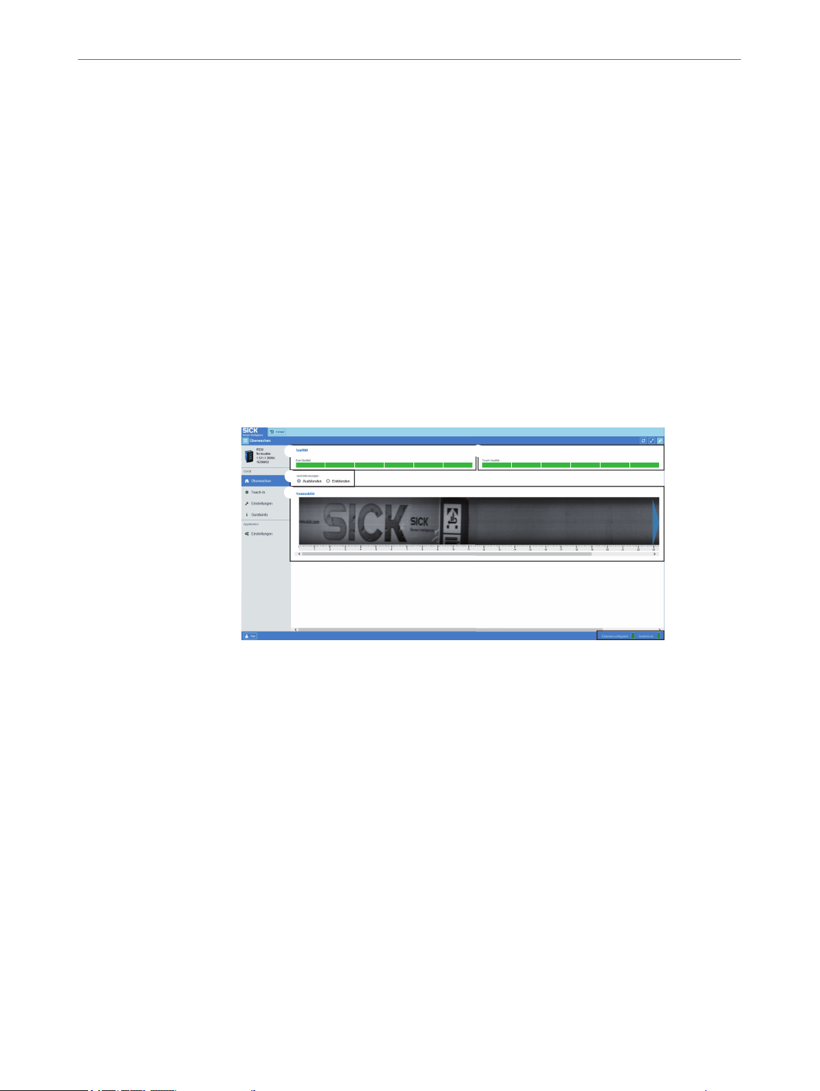
1
3
4
2
10 OPERATION VIA SOPASAIR
4 SOPASair software tool settings Position the cursor and click in this area of the
screen to switch to this mode. The corresponding interface is displayed at 6 on
the screen.
5 Display and user interface for the selected menu.
°
°
°
°
User level selection:
The available user levels are Run and Maintenance.
The factory-set password for the Maintenance user level is: “maintenance”.
It can be changed in the settings.
6 Status bar
°
°
10.2 Monitoring menu
The screen displayed when using the Endless material operating mode is shown in the
following figure.
Controls for teach-in
Display of the teach-in image
Display of the teach-in quality
Controls for saving the job
Displays the device status in text format and as a colored indicator
Displays the success of the process in text format and as a colored indicator
10.3
Figure 35: Appearance of the Monitoring menu when using Endless material operating mode
1
2
3
4
1. The bar graph displays the Quality of Run and the resultant switching accuracy. If
2. The bar graph displays the Quality of Teach and the resultant teach-in accuracy. If
3. If necessary, you can select to display the current teach-in image, e.g., to compare
4. An image of the object recorded when the process is running can be accessed by
Teach-in menu
The screen displayed after selecting the Teach-in menu is shown in the following figure.
This menu can be used to execute the teach-in process as a start-length teach-in.
Quality of Run bar graph
Quality of Teach bar graph
Button for hiding/showing the teach-in image
Teach-in image
fewer than 3 bars are displayed, the color changes to red to indicate that the mea‐
surement accuracy is inadequate and switching is not ensured.
fewer than 3 bars are displayed, the color changes to red to indicate that the
teach-in operation has failed.
the process image with the teach-in image.
double clicking. It is a snapshot; a continuous display is not possible due to the
volume of data involved.
46
O PE R AT I NG IN S TR U CT I ON S | PS30 8018916.ZYN1/2018-05-17 | SICK
Subject to change without notice
Page 47

1
3
4
2
5
6
7
1
OPERATION VIA SOPASAIR
Figure 36: Appearance of the Teach-in menu when using Endless material operating mode
Switching point shift (offset) button and blanked areas
1
Teach-in button
2
Field for setting the switching point offset
3
Teach-in image
4
Teach-in quality bar graph
5
Field for saving the job
6
Process status display
7
10
1. Activate/deactivate a switching point shift (offset) and blanked areas.
2. Start teach-in process (start-length teach-in). Define the length of the teach-in
area.
3. Activate the switching point offset.
4. Display of the teach-in image once the teach-in operation has been completed.
The reference areas are represented by blue rectangles.
5. The teach-in quality displayed as a bar graph.
6. Job save function for easy format change.
7. Process status display.
Figure 37: Appearance of the Teach-in menu with activated offset when using Endless material
operating mode.
Switching point offset marker
1
1. If a switching point offset is required, it can be enabled by selecting the checkbox.
The marker displayed in green (see 1 in the figure 37) can be moved by dragging
the dot to the desired position using the cursor. After deselecting the checkbox,
the marker is deleted and the switching point offset is deactivated.
8018916.ZYN1/2018-05-17 | SICK O P ER A TI N G I NS T RU C TI O NS | PS30
Subject to change without notice
47
Page 48

2
1 1
OPERATION VIA SOPASAIR
10
Figure 38: Appearance of the Teach-in menu with blanking.
Blanked areas or teach-in areas
1
Recalculation of the reference areas
2
Selecting the checkbox using the cursor enables the blanking function; up to two
areas (in Endless material operating mode) can then be blanked by moving the red
markers using the cursor (see 1 in the figure 38). Areas that have been blanked
are no longer analyzed. Blanking provides a way of ignoring varying elements,
for example a best-before date. In Single object operating mode, this provides a
way of restricting the area of the label to be analyzed. To activate the function, the
reference areas must be recalculated by selecting the “Recalculate teach” field
(see 2 in the figure 38). The reference areas are placed in the non-blanked area.
This can reduce the teach-in quality.
2. Click the “Start teach” field to initiate the teach-in process. When using the Single
object operating mode, move one object past the sensor. The teach image and ref‐
erence areas are then calculated. While this processing is in progress, this is indi‐
cated by the words “In progress” on the status bar as well as the color yellow.
Once the teach-in process is complete, the Quality of Teach is displayed as a bar
graph. When using the Endless material operating mode, continue moving the
material past the sensor for the entire duration of the teach-in process, as indi‐
cated in the status bar. The repeat length is also calculated by the sensor.
3. The required switching point offset can also be entered directly as a numerical
value in mm or it can be shifted to the left or right using the arrows displayed. In
Endless material operating mode, the switching point offset can only be set start‐
ing from the end of the format.
The value must be entered in mm. Instead of being at the end of the format, the
switching point is then offset by the distance value entered. When running a startlength teach-in, the length of the teach-in area must be specified. Values between
15 mm and 1,000 mm are permitted.
4. Display of the teach-in image once the teach-in operation has been completed.
The reference areas are represented by blue rectangles.
5. The bar graph displays the Quality of Teach and the resultant teach-in accuracy. If
fewer than 3 bars are displayed, the color changes to red to indicate that the
teach-in operation has failed.
6. Job assurance
The data of the current job including the teach-in image, teach-in data (blanked
areas and offset, for example), and the sensor configuration can be saved outside
of the sensor. This data is saved in a .job file. After this, the format can be
changed easily by selecting one of the .job files saved previously. If more than one
file is selected initially when a file is loaded, the correct format can be selected
from a preview screen.
48
O PE R AT I NG IN S TR U CT I ON S | PS30 8018916.ZYN1/2018-05-17 | SICK
Subject to change without notice
Page 49

7. Status bar
1
3
4
2
5
6
7
8
9
10.4 Settings menu
The first time the sensor is accessed, this happens automatically in the Run user level.
This user level allows the machine operator to access all of the options for teaching and
monitoring the sensor.
If any of the sensor settings (for example the sensor resolution) need to be changed,
this must be done using the Maintenance user level. The password when logging in for
the first time is “maintenance”. It can be changed at any time in the settings for the
SOPASair WebUI.
The screen displayed is shown in the following figure.
OPERATION VIA SOPASAIR
Displays the device status in text format and as a colored indicator
°
Displays the success of the process in text format and as a colored indicator
°
10
Figure 39: Layout of the user interface in the Settings menu
External teach-in mode
1
Error handling
2
Sensor resolution
3
Detection mode
4
Encoder type
5
Encoder direction
6
Encoder resolution
7
Q inversion
8
System settings
9
1. The following two options are available for configuring external teach-in:
a) Start-length teach-in
b) Start-stop teach-in
When using start-length teach-in, the desired length of the teach-in area must be
configured. The teach-in can be started via the Teach-in menu in SOPASair, or by
the machine controller by activating the ET input signal. When start-length teach-in
is selected, the teach-in is automatically ended by the sensor after the configured
length. When start-stop teach-in is selected, the teach-in process is automatically
ended when the ET input signal is deactivated.
2. Automatic error handling can be activated when using the Endless material operat‐
ing mode. The sensor sets up to 6 switching outputs based on the calculated
repeat length, even if the image could not be detected. This option is not available
for the Single object operating mode.
3. The sensor resolution can be set to a value between 100 μm and 1,000 μm. The
maximum possible object speed is determined by the resolution selected. The fol‐
lowing figure shows the relationship.
8018916.ZYN1/2018-05-17 | SICK O P ER A TI N G I NS T RU C TI O NS | PS30
Subject to change without notice
49
Page 50

10
8
6
4
1000 700 1000400 500 600300200
2
0
12
800 900
1
2
2
3
1
10 OPERATION VIA SOPASAIR
Figure 40: Maximum material speed as a function of sensor resolution
1
2
4. Either Endless material or Single object operating mode can be selected.
5. The available encoder type options are TTL/differential and HTL/push-pull.
6. The encoder resolution can be calculated in increments of 1 μm using the method
described in (see "Setting up the encoder", page 27).
7. The available options for specifying the rotational direction of the encoder are:
Auto (the sensor automatically determines the direction of rotation), CW (clock‐
wise) and CCW (counter-clockwise).
8. The Q switching output can be inverted.
9. The Ethernet interface can be configured here. The input field shown in the follow‐
ing figure is displayed. The device can be reset to the factory settings.
Maximum speed in m/s
Selected sensor resolution in µm
Figure 41: Appearance of the Settings menu screen after selecting the Ethernet setting
The IP address, the subnet mask, the gateway address, and the MAC address can
1
be configured here.
To use the DHCP function, select the checkbox.
2
The change is activated. The change will only take effect after the sensor has been
3
10.5 Device info menu
restarted.
The screen displayed after selecting the Device info menu is shown in the following fig‐
50
O PE R AT I NG IN S TR U CT I ON S | PS30 8018916.ZYN1/2018-05-17 | SICK
ure.
Subject to change without notice
Page 51

1
2
1
3
4
2
OPERATION VIA SOPASAIR 10
Figure 42: Appearance of the Device info menu screen
Device information
1
Location name
2
1. The following device information is displayed: item name, item number, serial num‐
ber, and firmware version number.
2. The user can assign a name to the specific sensor.
10.6 Settings menu (of the SOPASair WebUI)
The screen displayed after selecting the Settings menu is shown in the following figure.
Figure 43: Appearance of Settings operating mode in SOPASair
Language selection
1
Contrast mode
2
Compact mode
3
Change password
4
1. The available languages options are German and English. The password can also
be changed here when in Maintenance user level.
2. In addition to the normal display shown here in the figures, it is also possible to
select a high contrast black and white screen mode. This may be necessary under
strong ambient lighting.
3. In compact mode, the display is optimized for small screens.
4. When in Maintenance user level, the password for that user level can be changed
here.
10.7
Analysis menu
When in Maintenance user level, the Analysis menu can be used to display two differ‐
ent plots for analyzing the detected format length (in Endless material operating mode)
as well as the digital Q outputs and the status output.
8018916.ZYN1/2018-05-17 | SICK O P ER A TI N G I NS T RU C TI O NS | PS30
Subject to change without notice
51
Page 52

2
1
10 OPERATION VIA SOPASAIR
Detailed analyses of the switching behavior of the sensor can be carried out with the
Zoom function, plot offset, and the high-precision time axis in seconds or milliseconds.
Figure 44: Appearance of the Analysis menu screen
Display of format length over time
1
Display of the switching output (Q) and the status output over time
2
52
O PE R AT I NG IN S TR U CT I ON S | PS30 8018916.ZYN1/2018-05-17 | SICK
Subject to change without notice
Page 53

11 Troubleshooting
11.1 Notes on troubleshooting
Potential faults and rectification measures are described in the table below and in the
next chapter.
In the case of faults that cannot be rectified using the information below, please con‐
tact the manufacturer. See the back page for your agency.
Warnings
Warnings can only occur during a teach-in process. If there is a warning, the teach-in
process is run again in its entirety. If the teach-in result is inadequate, the teach-in
process must be run again.
Warnings are displayed in the “ErrCod” parameter with “Wrn” and a number, see "Moni‐
toring menu", page 42.
Errors
Errors can occur during a teach-in process or as a result of other events, for example a
short-circuit. If an error occurs, the teach-in process is interrupted. If valid teach-in data
is already available, these will be used.
TROUBLESHOOTING 11
11.2
Errors are displayed in the “ErrCod” parameter with “Err” and a number, see "Monitor‐
ing menu", page 42.
Possible error indicators
Table 19: Possible error indicators
Error code
indicator on
the display
NoErr No error is present. -
Wrn011 The taught-in format length is greater
Wrn012 Sensor signal is overridden due to over‐
Wrn013 Contrast too low in the taught-in format. Check the mounting, see "Mounting",
Wrn015 The taught-in format was larger than the
Err001 A short-circuit exists at the Q
Err010 The taught-in format length is less than
Err014 The image speed was too fast during
Err016 The blanked area is too large, or insuffi‐
Possible causes (SOPASair display) Troubleshooting
than 1,000 mm.
exposure.
actual format length (in Endless mater‐
ial).
tus
the minimum teach-in length, i.e.
15 mm.
the teach-in process.
cient reference areas were found in the
pattern.
OUT
output.
OUT
or Sta‐
Repeat the teach-in process with a
smaller teach-in range, see "Teach-in
menu", page 46.
Check the mounting, see "Mounting",
page 17.
page 17.
If necessary, select another image
area with a higher contrast.
Repeat the teach-in process with a
smaller teach-in range.
Eliminate the short circuit.
Repeat the teach-in process with a
larger teach-in range.
Repeat the teach-in process with a
lower speed.
Select a smaller area to be blanked.
Repeat the teach-in process.
8018916.ZYN1/2018-05-17 | SICK O P ER A TI N G I NS T RU C TI O NS | PS30
Subject to change without notice
53
Page 54

11 TROUBLESHOOTING
Error code
indicator on
the display
Err017 No taught-in image available. Repeat the teach-in process.
Err018 The label can not be clearly detected at
Err101 Device/operation is locked. Contact your SICK agency. See the
11.3 Troubleshooting guide
Possible causes of faults
The possible types of faults can be grouped into the following categories:
Faults caused by the combination pattern sensor – encoder
•
Faults caused by mounting or teaching-in
•
Faults caused by the system
•
Faults caused by the network connection and SOPASair
•
Possible causes (SOPASair display) Troubleshooting
Change the angle or position of the
the selected position.
sensor. Repeat the teach-in process.
Contact your SICK agency if the error
occurs again. See the addresses on
the rear of these operating instruc‐
tions.
addresses on the rear of these operat‐
ing instructions.
11.3.1 Faults caused by the combination pattern sensor – encoder
Common causes of faults
Common causes of pattern sensor malfunction are:
incorrectly connected encoder
•
incorrectly configured encoder/sensor
•
unsuitable encoder
•
Check the wiring
The following encoder cables must be connected to the pattern sensor:
“HTL” encoder type: cables A and B
•
“TTL” encoder type: cables A, A‘, B and B‘
•
For the pattern sensor connection example, see see "Pin assignment of the connec‐
tions", page 25.
Check the mounting
→ See page 61, fig. 39 and page 21, chapter 6.
Check the encoder settings
For the encoder setup, see "Setting up the encoder", page 27.
For the menu structure, see "Menu structure", page 69.
54
Check the following points:
The encoder type set on the pattern sensor must match the type of connected
•
encoder. The available options are “HTL” or “TTL”.
Setting the encoder type for the sensor: see "Setting up the encoder",
°
page 27
Encoder type of the connected encoder: see the data sheet.
°
O PE R AT I NG IN S TR U CT I ON S | PS30 8018916.ZYN1/2018-05-17 | SICK
Subject to change without notice
Page 55

1
2
3
4
1
2
3
4
TROUBLESHOOTING 11
The encoder type set on the pattern sensor must match the bar width of the
•
encoder (see "Setting up the encoder", page 27, “EncRes” parameter).
You can calculate the encoder resolution as described in the following section.
Calculating the encoder resolution
Figure 45: Encoder mounting
Pattern sensor
1
Machine cycle/motor feedback/encoder
2
U
3
Material guide roller
4
Figure 46: Calculating the encoder resolution
U
1
S
2
n
3
Encoder
4
The encoder resolution (EncRes) can be calculated using the following formula:
S = U/n
S: Encoder resolution
U = External circumference of the roller
n: Number of encoder bars in 360°
Checking the device function
You can verify that the device is functioning properly, and therefore wired and config‐
ured correctly, by means of the displayed encoder position (see "Monitoring menu",
page 42, “EncPos” parameter).
8018916.ZYN1/2018-05-17 | SICK O P ER A TI N G I NS T RU C TI O NS | PS30
Subject to change without notice
55
Page 56

11 TROUBLESHOOTING
CW direction (clockwise): Counter increases in increments of the encoder resolu‐
•
tion
CCW direction (counter-clockwise): Counter decreases in increments of the
•
encoder resolution
11.3.2 Faults caused by mounting or teaching-in
If the teach-in quality is too low, fewer than 3 bars flash in the display. In SOPASair, the
Quality of teach-in graph shows less than 3 bars.
Check the individual items according to the following table.
Table 20: Faults caused by mounting or teaching-in
Cause/item to be checked Thorough check Troubleshooting
Material is highly glossy. Check the sensor distance
The sensor is not installed at
the correct height.
Sensor does not detect the
printed area correctly.
For example, a pattern area
with significant label edge fea‐
tures is not detected, or the
contrast is too low.
The taught-in pattern length is
too long or too short.
The taught-in pattern area
must be larger than 15 mm
and no greater than the object
length in Single object operat‐
ing mode, or the repeated
length in Endless material
operating mode.
The material was not moved in
front of the sensor correctly
during the teach-in process.
The rotational direction during
the teach-in process does not
match the configured encoder
direction.
To ensure a correct signal, the
rotational direction during the
teach-in process must match
the configured encoder direc‐
tion.
and angle, see "Mounting
requirements", page 17.
View and check the teach-in
image using SOPASair, see
"Teach-in menu", page 46.
The messages “Wrn11” and
“Wrn15” are displayed in the
“Monitr” menu (ErrCod submenu).
Check the teach-in length (see
"Monitoring menu", page 42,
“TeaLen” and “ActLen” para‐
meters).
View and check the teach-in
image using SOPASair, see
"Analysis menu", page 51.
Check the rotational direction
configured in the “EncPos”
parameter in the “Monitr”
menu. The numerical value
must change. A “+” must be
displayed before the numeri‐
cal value. The “+” indicates
that the rotational direction
during the teach-in process
and the current encoder direc‐
tion match. A “-” indicates that
the two directional rotations
do not match. The Q switching
output is LOW.
If necessary, do not use the
prescribed distance and angle.
For example, use a higher or
lower sensor tilt angle.
Correct the sensor height, see
"Mounting requirements",
page 17.
Rerun the teach-in and ensure
the permissible range for the
format length is adhered to.
Rerun the teach-in. Ensure that
the material is not slanted, rip‐
pled, or moved in front of the
sensor at the wrong angle dur‐
ing the teach-in process, see
"Mounting requirements",
page 17.
Rerun the teach-in. Move the
material in the other rotational
direction.
56
O PE R AT I NG IN S TR U CT I ON S | PS30 8018916.ZYN1/2018-05-17 | SICK
Subject to change without notice
Page 57

TROUBLESHOOTING 11
Cause/item to be checked Thorough check Troubleshooting
Teach-in quality is poor.
Reference positions are
bunched together in one place
instead of being distributed
equally across the format
length.
Are there enough dis‐
•
tinctive features in the
teach-in pattern (suffi‐
cient contrast)?
Is the sensor lens dirty
•
(contamination will
result in reference posi‐
tions being positioned
incorrectly)?
Are some pixels overex‐
•
posed (are some areas
of the sensor image very
bright)?
If the pattern being used
•
does not have very many
features, all of the refer‐
ence points will be dis‐
tributed across these few
features. Poor distribution
results in poor teach-in
quality. The better the
distribution, the more reli‐
able detection will be.
Contamination of the
•
front screen/lens of the
sensor can lead to refer‐
ence points being distrib‐
uted to positions where
the teach-in material con‐
tains no features. Clean
the sensor and repeat the
teach-in process.
Overexposure leads to
•
contrast variations in the
affected parts of the
image. These high con‐
trasts cause the sensor
to locate its reference
points in these positions.
However, since these
overexposures can never
be reproduced, the detec‐
tion function will not be
reliable. Check the tilt
angle of the sensor to
avoid direct reflections.
Repeat the teach-in
process.
11.3.3 Faults caused by the system
Check the individual items according to the following table.
Table 21: Faults caused by the system
Cause/item to be checked Example Troubleshooting
Material slippage is too great. Bad material transport, and
consequently the encoder sig‐
nal does not correspond to
the path covered.
Material stretch is too great. Driving force is not uniform,
and the material is flexible.
Image features are not identi‐
cal. Details of the formats dif‐
fer.
Material with a large surface
area is used and the back‐
ground is irregular,
for example due to contamina‐
tion.
8018916.ZYN1/2018-05-17 | SICK O P ER A TI N G I NS T RU C TI O NS | PS30
Subject to change without notice
The image features are in the
same place, but there is a
change in the writing.
The guide roller is contami‐
nated.
Replace the material. Rerun
the teach-in.
Clean guide roller. Rerun the
teach-in.
57
Page 58

11 TROUBLESHOOTING
Cause/item to be checked Example Troubleshooting
The system’s EMC radiated
emission is too high.
11.3.4 Faults caused by the network connection and SOPASair
NOTE
We recommend having your network administrator connect the pattern sensor to the
network.
Check the individual items according to the following table.
Table 22: Faults caused by the network connection and SOPASair
Cause/item to be checked Thorough check Troubleshooting
The sensor is connected to a
network using a network
cable.
The sensor IP configuration is
not correct.
The network settings in SOPA‐
Sair are incorrect.
After entering the new IP
address, the supply voltage of
the sensor was not switched
off, then back on (restart).
The sensor does not adopt the
new IP address until the sen‐
sor is restarted.
The IP configuration to the
existing network is not com‐
patible.
Strong stray radiation in the
vicinity, e.g., from a frequency
converter.
The “Link” LED on the
•
sensor must light up
(Ethernet connection
OK).
The “Act” LED on the
•
sensor must light up
(data transfer).
Check the IP configuration on
the sensor, see "Operation via
Ethernet TCP/IP", page 44.
Check the following informa‐
tion on the “IP communica‐
tion” page (menu path: Net‐
work assistant > “IP communi‐
cation” page), see "Monitoring
menu", page 46.
Check the IP configuration on
the sensor, see "Ethernet con‐
figuration (Ethern) parameter",
page 36.
Check the IP address,
•
subnet mask, and gate‐
way address settings,
see "Operation via Ether‐
net TCP/IP", page 44.
Use the “ping” diagnos‐
•
tics tool to check
whether the sensor is
correctly integrated in its
IP network. The sensor
must answer with an
echo ICMP package
(echo request). The
“Activity” LED on the
sensor must light up.
Check the wiring, see
•
"Notes on the electrical
installation", page 20.
Always use shielded and
•
twisted cables for the
sensor. For pre-assem‐
bled cables, see "Connec‐
tivity", page 66.
Switch the supply voltage off
and back on after checking the
IP configuration.
Contact your network adminis‐
trator.
58
O PE R AT I NG IN S TR U CT I ON S | PS30 8018916.ZYN1/2018-05-17 | SICK
Subject to change without notice
Page 59

TROUBLESHOOTING 11
Cause/item to be checked Thorough check Troubleshooting
The configured SOPASair Net
Scan timeout is too low for the
connected network.
Check the value of the “Scant‐
imeout [ms]” parameter. The
factor setting is 500 [ms].
Path: Network configuration >
IP configuration > Extended.
Increase the value of the
“Scantimeout [ms]” parameter,
e.g. to 4,000.
8018916.ZYN1/2018-05-17 | SICK O P ER A TI N G I NS T RU C TI O NS | PS30
Subject to change without notice
59
Page 60

12 MAINTENANCE
12 Maintenance
12.1 Maintenance
During operation, the device works maintenance-free.
Depending on the assignment location, the following preventive maintenance tasks
may be required for the device at regular intervals:
Table 23: Maintenance schedule
Maintenance work Interval Implementation
Clean housing and front screen
Check screw connections and plug
connectors
12.2 Cleaning the device
At regular intervals (e.g., weekly), check the light emission window and the housing of
the device for dirt. This is especially relevant in harsh operating environments (dust,
abrasion, damp, fingerprints, etc.). The lens of the light emission window must be kept
clean and dry during operation.
Cleaning interval depends on ambi‐
ent conditions and climate
Every 6 months Specialist
Specialist
NOTICE
Device damage due to improper cleaning!
Improper cleaning may result in device damage.
■
Only use suitable cleaning agents.
■
Never use sharp objects for cleaning.
Cleaning the light emission window
NOTICE
Damage to the light emission window!
Reduced reading performance due to scratches or streaks on the light emission win‐
dow!
Clean the light emission window only when wet.
b
Use a mild cleaning agent that does not contain powder additives. Do not use
b
aggressive cleaning agents, such as acetone, etc.
Avoid any movements that could cause scratches or abrasions on the light emis‐
b
sion window.
Only use cleaning agents suitable for the lens material.
b
NOTE
Static charge may cause dust particles to stick to the light emission window. This effect
can be avoided by using an anti-static glass cleaner in combination with the SICK lens
cloth (can be obtained from www.sick.com).
60
NOTE
If the light emission window is scratched or damaged (cracked or broken), the device
must be replaced. Contact SICK Service to arrange this.
O PE R AT I NG IN S TR U CT I ON S | PS30 8018916.ZYN1/2018-05-17 | SICK
Subject to change without notice
Page 61

MAINTENANCE 12
Cleaning the housing
In order to ensure that the heat produced by the internal power loss is adequately dissi‐
pated, the housing surface must be kept clean.
8018916.ZYN1/2018-05-17 | SICK O P ER A TI N G I NS T RU C TI O NS | PS30
Subject to change without notice
61
Page 62

13 DECOMMISSIONING
13 Decommissioning
13.1 Disassembly and disposal
Disassembling the device
1. Switch off the supply voltage to the device.
2. Detach all connecting cables from the device.
3. If the device is being replaced, mark its position and alignment on the bracket or
surroundings.
4. Detach the device from the bracket.
Disposing of the device
Any device which can no longer be used must be disposed of in an environmentally
friendly manner in accordance with the applicable country-specific waste disposal regu‐
lations. As it is categorized as electronic waste, the device must never be disposed of
with household waste!
13.2 Returning devices
Do not dispatch devices to the SICK Service department without consultation.
b
NOTE
To enable efficient processing and allow us to determine the cause quickly, please
include the following when making a return:
■
Details of the contact person
■
Description of the application
■
Description of the fault that occurred
62
O PE R AT I NG IN S TR U CT I ON S | PS30 8018916.ZYN1/2018-05-17 | SICK
Subject to change without notice
Page 63

14 Technical data
20,6
46
18
4
40,2
4
5,2
67
5
27
71,6
7,8
15,3
69,3
4
1
1
2
2
4
5678
3
14.1 Dimensional drawings
TECHNICAL DATA 14
14.2 Optics/features
Figure 47: Dimensions in mm
Center of the optical axis
1
Fixing hole, Ø 4.2 mm
2
M12 male connector, 12-pin/M12 female connector, 4-pin with 90° rotation
3
Display and pushbuttons
4
Function indicator (green) “on”
5
Function indicator (yellow) “Q”
6
Function indicator (green) “Link”
7
Function indicator (yellow) “Act”
8
Table 24: Optics/features
Attribute Description
Light sender
Wavelength 400 nm ... 700 nm
Light spot size 65 mm x 3 mm
Sensing distance 20 mm
Sensing distance tolerance ± 2.5 mm
Setting Start-stop teach-in, Start-length teach-in
Format length (min) 15 mm
Format length (max) 1,000 mm
Format height (min) 10 mm
Lateral movement tolerance ± 5 mm
1)
LED, white
8018916.ZYN1/2018-05-17 | SICK O P ER A TI N G I NS T RU C TI O NS | PS30
Subject to change without notice
63
Page 64

14 TECHNICAL DATA
14.3 Supply
Attribute Description
Initialization time < 10 s
Reproducibility
2)
0.1 mm (at 3 m/s), 0.15 mm (at 5 m/s) or 0.3 mm (at
10 m/s) (depending on the configured sensor resolution)
Storage time (ET) ≥ 2 s, non-volatile memory
1)
Average service life 100,000 h at TU = +25 °C
2)
Statistical error 2 σ
Table 25: Supply
Attribute Description
Supply voltage U
V
12 V DC … 30 V DC
Power consumption (without load) < 6 W
Residual ripple < 5 Vss within permitted supply voltage UV (must not
exceed or be less than the UV tolerances.)
1)
Limit values: Max. 8 A for operation in a short-circuit protected network
14.4 Inputs
14.5 Outputs
Table 26: Inputs
Attribute Features
Input, teach-in (ET)
Input, blanking input (AT)
1)
PNP
•
Teach: U = 12 V ... < U
•
Run: U < 2 V
•
PNP
•
Blanked: U = 12 V … < U
•
Free: U < 2 V
•
V
V
Circuit protection UV connections, reverse polarity protected, interference-
pulse suppression
1)
Blanking out of identical image areas
Table 27: Outputs
Attribute Feature
Switching output (Q
Circuit protection Q
Maximum output current < 100 mA (Total I
) PNP
OUT
HIGH = UV – ≤ 2 V, switching signal for 5 mm
•
LOW < 0.5 V
•
output, short-circuit protected
out
= Q + Status
OUT
OUT
)
14.6 Interfaces
64
O PE R AT I NG IN S TR U CT I ON S | PS30 8018916.ZYN1/2018-05-17 | SICK
Table 28: Interfaces
Attribute Features
Ethernet TCP/IP Configuration interface
Subject to change without notice
Page 65

14.7 Encoder
Table 29: Encoder
Attribute Features
Encoder resolution 100 μm ... 600 μm (in 1 μm)
Encoder input
14.8 Ambient conditions
Table 30: Ambient conditions
Attribute Features
Protection class III, for operation with safety extra-low voltage (SELV/
Electromagnetic compatibility EN 61000-6-2, EN 55011, Class A
Ambient temperature range –10 °C … +55 °C
Storage temperature range –20 °C … +75 °C
Ambient light immunity 30,000 lx
Enclosure rating IP 65
Enclosure protection type according
to UL:
Max. traversing speed 10 m/s
Vibration resistance (sine) EN 60068-2-6
Random EN 60068-2-64
Shock resistance/impact load EN 60086-2-27
TECHNICAL DATA 14
Differential: 4.5 V ... 5.5 V / TTL / RS-422
•
Single ended: 12 V ... 30 V / HTL / Push-Pull
•
PELV)
Enclosure type 1
14.9 Structural design
Table 31: Structural design
Attribute Features
Dimensions → See page 63, section 14.1.
Weight 325 g
Materials Housing: Metal, discharge plate: Plastic
Connections
Display 6-digit with a 5 x 7 dot matrix
1)
Use twisted and shielded cables
1)
Male connector, M12, 12-pin
•
M12 Ethernet connection, 4-pin
•
8018916.ZYN1/2018-05-17 | SICK O P ER A TI N G I NS T RU C TI O NS | PS30
Subject to change without notice
65
Page 66

15 ACCESSORIES
15 Accessories
NOTE
Accessories can be found on the online product page at:
www.sick.com/PS30
b
15.1 Connectivity
15.1.1 Female cable connectors with cables
Table 32: Female cable connectors with cables
Description Type Order no.
M12 female cable connector, 12-pin,
straight, 5 m, shielded, twisted-pair
wires
M12 female cable connector, 12-pin,
angled, 5 m, shielded, twisted-pair
wires
DOL-1212-G05MAS02 6042754
DOL-1212-W05MAS02 6044109
15.1.2 Connection cable
Table 33: Connection cable
Description Type Order no.
M12 connection cable. 12-pin,
straight male connector/straight
female connector, 5 m, shielded,
twisted-pair wires
15.1.3 Ethernet cables
Table 34: Ethernet cables
Description Type Order no.
Ethernet cable, 4-wire, shielded, M12
male connector, straight, 4-pin (Dcoded), RJ-45 male connector, 8-pin,
5 m
Ethernet cable, 4-wire, shielded, M12
male connector, angled, 4-pin (Dcoded), RJ-45 male connector, 8-pin,
5 m
DSL-1212-G05MAS02 6045234
Connection cable (male connec‐
tor-male connector)
Connection cable (male connec‐
tor-male connector)
6034415
6039488
66
O PE R AT I NG IN S TR U CT I ON S | PS30 8018916.ZYN1/2018-05-17 | SICK
Subject to change without notice
Page 67

15.2 Mounting systems
110
66
2,5
50
A
1,5 x 45° 1,5 x 45°
Ø 12
A
B
R1
2
1,5 x 45°
1,5 x 45°
90°
Ø 12
15.2.1 Universal clamp plate
Figure 48: Universal clamp plate, measurements in mm
Table 35: Universal clamp plate
Description Type Part no.
Plate N04 for universal clamp, steel,
zinc-coated, incl. universal clamp and
mounting hardware
ACCESSORIES 15
BEF-KHS-N04 2051610
15.2.2 Mounting rods
Figure 49: Mounting rod, straight, all dimensions in mm
Table 36: Mounting rod, straight
Description Type Part no.
Mounting rod, straight, 200 mm,
BEF-MS12G-A 4056054
zinc-coated steel, without mounting
hardware
8018916.ZYN1/2018-05-17 | SICK O P ER A TI N G I NS T RU C TI O NS | PS30
Subject to change without notice
Figure 50: Mounting rod, L-shaped, all dimensions in mm
67
Page 68

15 ACCESSORIES
Table 37: Mounting rod, L-shaped
Description Type Part no.
Mounting rod, L-shape, 250 mm x
BEF-MS12L-B 4056053
250 mm, zinc-coated steel, without
mounting hardware
68
O PE R AT I NG IN S TR U CT I ON S | PS30 8018916.ZYN1/2018-05-17 | SICK
Subject to change without notice
Page 69

16 Menu structure
Setup
EncTyp
EncRes
…
…
EncDir …
Store? Settng
−−−−−−
−−−−−−
−−−−−−
−−−−−−
−−−−−−
−−−−−−
−−−−−−
−−−−−−
RUN
−−−−−−
−−−−−−
−−−−−−
−−−−−−
−−−−−−
−−−−−−
−−−−−−
−−−−−−
RUN
−−−−−−
−−−−−−
−−−−−−
−−−−−−
−−−−−−
−−−−−−
−−−−−−
−−−−−−
QoR
0000
Monitr
QoT
TeaLen
ActLen
EncPos
ErrCod
(2sec)
0000
RUN
0000
RUN
0000
RUN
IdArea Area1
Area2
Apply?
Start?
Start?
Teach
StaLen
OffSet
Blank
0000
0000
Start?
−−−−−−
−−−−−−
−−−−−−
−−−−−−
−−−−−−
−−−−−−
−−−−−−
−−−−−−
...
...
16.1 Setup menu
Figure 51: Setup menu
16.2 Monitr menu
MENU STRUCTURE 16
16.3 Teach menu
Figure 52: Monitr menu
Figure 53: Teach menu
8018916.ZYN1/2018-05-17 | SICK O P ER A TI N G I NS T RU C TI O NS | PS30
Subject to change without notice
69
Page 70

Settng
EncTyp
ModeMode
EncRes
EncDir ...
Reset no
ModeEthern
ETeach
DHCP
StaSto
StaLen 0000
...
...
Single
Endl
Single
Endl
MAC ID
IP-Adr
SubMas
D-Gate
according to first setup
according to first setup
according to first setup
IP-Adr
Info
SwVers
SerNr
16 MENU STRUCTURE
16.4 Settng menu
16.5
Info menu
Figure 54: Settng menu
Figure 55: Info menu
70
O PE R AT I NG IN S TR U CT I ON S | PS30 8018916.ZYN1/2018-05-17 | SICK
Subject to change without notice
Page 71

17 Annex
17.1 EU declaration of conformity and certificates
The EU declaration of conformity and other certificates can be downloaded from the
Internet at:
www.sick.com/PS30
b
17.2 Certification according to UL60947-5-2
The PSS Prime Print Detector is certified in accordance with UL60947-5-2 if it is sup‐
plied with voltage by LPS or Class 2 power supply units.
ANNEX
17
17.3 Licenses
The certification is only valid with corresponding device identification on the type label
of the respective device.
In the pattern sensors, LwIP 1.4 is used in accordance with the modified BSD license,
see http://savannah.nongnu.org/projects/lwip/
lwIP is licenced under the BSD licence:
All rights reserved.
Redistribution and use in source and binary forms, with or without modification, are
permitted provided that the following conditions are met:
1 Redistributions of source code must retain the above copyright notice, this list of
conditions and the following disclaimer.
2 Redistributions in binary form must reproduce the above copyright notice, this list
of conditions and the following disclaimer in the documentation and/or other
materials provided with the distribution.
3 The name of the author may not be used to endorse or promote products derived
from this software without specific prior written permission.
OR IMPLIED WARRANTIES, INCLUDING, BUT NOT LIMITED TO, THE IMPLIED WAR‐
RANTIES OF MERCHANTABILITY AND FITNESS FOR A PARTICULAR PURPOSE ARE DIS‐
CLAIMED. IN NO EVENT SHALL THE AUTHOR BE LIABLE FOR ANY DIRECT, INDIRECT,
INCIDENTAL, SPECIAL, EXEMPLARY, OR CONSEQUENTIAL DAMAGES (INCLUDING, BUT
NOT LIMITED TO, PROCUREMENT OF SUBSTITUTE GOODS OR SERVICES; LOSS OF USE,
DATA, OR PROFITS; OR BUSINESS INTERRUPTION) HOWEVER CAUSED AND ON ANY
THEORY OF LIABILITY, WHETHER IN CONTRACT, STRICT LIABILITY, OR TORT (INCLUDING
NEGLIGENCE OR OTHERWISE) ARISING IN ANY WAY OUT OF THE USE OF THIS SOFT‐
WARE, EVEN IF ADVISED OF THE POSSIBILITY OF SUCH DAMAGE.
Registration date: Thu17 Oct 2002 21:13:13 UTC
License: Modified BSD license
8018916.ZYN1/2018-05-17 | SICK O P ER A TI N G I NS T RU C TI O NS | PS30
Subject to change without notice
71
Page 72

INDEX
18
18 Index
A
Accessories......................................................................................... 66
adjustment tool................................................................................... 19
Ambient conditions............................................................................. 65
Arrangement....................................................................................... 18
B
Bar graph............................................................................................. 15
Blanking out image areas................................................................... 41
C
Calculating the encoder resolution.................................................... 28
Cleaning the device............................................................................ 60
Commissioning................................................................................... 27
Connecting the device electrically..................................................... 24
connection diagram............................................................................ 25
Connectivity......................................................................................... 66
conversions............................................................................................ 8
Customer service.................................................................................. 7
D
Device view.......................................................................................... 11
Dimensions......................................................................................... 63
Disassembly........................................................................................ 62
Display................................................................................................. 15
Display and operating elements........................................................ 13
disposal............................................................................................... 62
E
Electricians............................................................................................ 9
error..................................................................................................... 53
Ethernet TCP/IP................................................................................... 44
EU declaration of conformity.............................................................. 71
Explanation of symbols......................................................................... 6
Operating modes................................................................................ 12
operational safety................................................................................. 9
Outputs................................................................................................ 64
P
Pushbuttons........................................................................................ 14
R
Repair.................................................................................................. 10
Reset.................................................................................................... 37
Returning............................................................................................. 62
RUN...................................................................................................... 14
S
Scope of delivery................................................................................. 17
Sensing distance................................................................................ 17
SET....................................................................................................... 14
Setting up the encoder....................................................................... 27
Skilled personnel................................................................................... 9
SOPASair.............................................................................................. 45
Storage................................................................................................ 16
Supply.................................................................................................. 64
Switching point offset......................................................................... 39
T
teach-in.................................................................................. 34, 34, 35
Transport............................................................................................. 16
troubleshooting................................................................................... 53
Troubleshooting................................................................................... 53
Troubleshooting guide........................................................................ 54
Type label............................................................................................. 11
W
Wiring notes........................................................................................ 21
F
Function............................................................................................... 12
Function indicators............................................................................. 14
H
Hazard warnings.................................................................................... 9
I
Improper use......................................................................................... 8
Inputs................................................................................................... 64
Intended use.......................................................................................... 8
Interfaces............................................................................................ 64
IP network configuration.................................................................... 44
L
LEDs..................................................................................................... 14
Licenses.............................................................................................. 71
Limitation of liability.............................................................................. 8
M
Maintenance....................................................................................... 60
MEN..................................................................................................... 14
Menu structure.................................................................................... 69
Mounting systems............................................................................... 67
O
offset.................................................................................................... 39
72
O PE R AT I NG IN S TR U CT I ON S | PS30 8018916.ZYN1/2018-05-17 | SICK
Subject to change without notice
Page 73

INDEX 18
8018916.ZYN1/2018-05-17 | SICK O P ER A TI N G I NS T RU C TI O NS | PS30
Subject to change without notice
73
Page 74

Further locations at www.sick.com
Australia
Phone +61 (3) 9457 0600
1800 33 48 02 – tollfree
E-Mail sales@sick.com.au
Austria
Phone +43 (0) 2236 62288-0
E-Mail office@sick.at
Belgium/Luxembourg
Phone +32 (0) 2 466 55 66
E-Mail info@sick.be
Brazil
Phone +55 11 3215-4900
E-Mail comercial@sick.com.br
Canada
Phone +1 905.771.1444
E-Mail cs.canada@sick.com
Czech Republic
Phone +420 2 57 91 18 50
E-Mail sick@sick.cz
Chile
Phone +56 (2) 2274 7430
E-Mail chile@sick.com
China
Phone +86 20 2882 3600
E-Mail info.china@sick.net.cn
Denmark
Phone +45 45 82 64 00
E-Mail sick@sick.dk
Finland
Phone +358-9-25 15 800
E-Mail sick@sick.fi
France
Phone +33 1 64 62 35 00
E-Mail info@sick.fr
Germany
Phone +49 (0) 2 11 53 01
E-Mail info@sick.de
Hong Kong
Phone +852 2153 6300
E-Mail ghk@sick.com.hk
Hungary
Phone +36 1 371 2680
E-Mail ertekesites@sick.hu
India
Phone +91-22-6119 8900
E-Mail info@sick-india.com
Israel
Phone +972-4-6881000
E-Mail info@sick-sensors.com
Italy
Phone +39 02 27 43 41
E-Mail info@sick.it
Japan
Phone +81 3 5309 2112
E-Mail support@sick.jp
Malaysia
Phone +603-8080 7425
E-Mail enquiry.my@sick.com
Mexico
Phone +52 (472) 748 9451
E-Mail mario.garcia@sick.com
Netherlands
Phone +31 (0) 30 229 25 44
E-Mail info@sick.nl
New Zealand
Phone +64 9 415 0459
0800 222 278 – tollfree
E-Mail sales@sick.co.nz
Norway
Phone +47 67 81 50 00
E-Mail sick@sick.no
Poland
Phone +48 22 539 41 00
E-Mail info@sick.pl
Romania
Phone +40 356-17 11 20
E-Mail office@sick.ro
Russia
Phone +7 495 283 09 90
E-Mail info@sick.ru
Singapore
Phone +65 6744 3732
E-Mail sales.gsg@sick.com
Slovakia
Phone +421 482 901 201
E-Mail mail@sick-sk.sk
Slovenia
Phone +386 591 78849
E-Mail office@sick.si
South Africa
Phone +27 (0)11 472 3733
E-Mail info@sickautomation.co.za
South Korea
Phone +82 2 786 6321
E-Mail info@sickkorea.net
Spain
Phone +34 93 480 31 00
E-Mail info@sick.es
Sweden
Phone +46 10 110 10 00
E-Mail info@sick.se
Switzerland
Phone +41 41 619 29 39
E-Mail contact@sick.ch
Taiwan
Phone +886-2-2375-6288
E-Mail sales@sick.com.tw
Thailand
Phone +66 2 645 0009
E-Mail marcom.th@sick.com
Turkey
Phone +90 (216) 528 50 00
E-Mail info@sick.com.tr
United Arab Emirates
Phone +971 (0) 4 88 65 878
E-Mail info@sick.ae
United Kingdom
Phone +44 (0)17278 31121
E-Mail info@sick.co.uk
USA
Phone +1 800.325.7425
E-Mail info@sick.com
Vietnam
Phone +65 6744 3732
E-Mail sales.gsg@sick.com
8018916.ZYN1/2018-05-17/en
SICK AG | Waldkirch | Germany | www.sick.com
 Loading...