

SICK Profiler 2, PRO2-N100B25A1, 6052874, PRO2-P100B25A1, 6052873 Operating Instructions Manual
Page 1
Proler™ 2
SHORT RANGE DISTANCE SENSOR
OPERATING INSTRUCTIONS
Page 2

Copyright protection!
This work is copyright-protected. The rights founded by
this shall remain with company SICK AG. Reproduction
of the work or parts of this work shall only be permissible
within the limits of the legal provisions of copyright law.
Changes and abbreviations of this work are prohibited
without the express written agreement of SICK AG.
2 © SICK AG • Subject to change without notice. • 8017035/ZMO9/2017-06-08
Page 3

Table of contents
1 Introduction ........................................................................................ 8
1.1 Warranty .....................................................................................8
2 Safety Precautions............................................................................. 9
2.1 Safety Precaution Symbols ....................................................... 9
2.2 Mandatory Precautions .............................................................9
2.3 Precautions for Laser Use ...................................................... 10
2.3.1 Installation Precautions.......................................... 10
2.4 Warning Labels ....................................................................... 11
3 Information Before Use ................................................................... 12
3.1 General Description ................................................................ 12
3.2 Package Contents ................................................................... 13
3.2.1 Included Items ........................................................ 13
3.2.2 Options .................................................................... 13
3.3 Names and Functions of Parts .............................................. 14
3.3.1 Sensor ..................................................................... 14
3.3.2 Laser Emission and Measurement Ranges .......... 15
3.3.3 Cable Wire Colors and Roles .................................. 16
3.4 Installation .............................................................................. 17
3.4.1 Notes for installation .............................................. 17
3.4.2 Installing the Sensor ............................................... 17
4 Setup and Measurement Procedures ............................................. 18
4.1 Before Using the Proler 2 ..................................................... 18
4.1.1 Procedure for Using the Sensor ............................. 18
4.1.2 Setup and Measurement Process ......................... 19
4.2 Quick Setup ............................................................................. 20
4.2.1 Basic Measurement Settings ................................. 20
4.2.2 Return to Main Menu/Measurement Screen ........ 21
4.2.3 Initialize Settings ..................................................... 22
5 Operating the Sensor ....................................................................... 23
5.1 Sensor Screen ......................................................................... 23
5.1.1 Details of the Screen .............................................. 23
5.1.2 Screen Types and Switching Between Screens .... 24
5.1.3 Key Lock Function ................................................... 25
5.2 Main Screen ............................................................................ 25
8017035/ZMO9/2017-06-08 • © SICK AG • Subject to change without notice. 3
Page 4

5.2.1 Main ......................................................................... 25
5.2.2 Input/Trigger ........................................................... 26
5.2.3 Storage .................................................................... 27
5.2.4 Other ........................................................................ 30
5.3 Setting ..................................................................................... 32
5.3.1 Camera .................................................................... 32
5.3.2 Prole ....................................................................... 35
5.3.3 Area .......................................................................... 38
5.4 Graph/Calc .............................................................................. 40
5.4.1 Graph Items (Area 1 to area 4) .............................. 41
5.4.2 Calc Items (Calculation 1 and calculation 2) ........ 42
5.5 Output ...................................................................................... 43
5.5.1 Output Items (OUT1 to OUT3) ................................ 44
5.5.2 Output Items (OUTA) ............................................... 45
6 PRO2-Navigator Setup Software ..................................................... 47
6.1 Setup Software Requirements ............................................... 47
6.1.1 Operating Environment ........................................... 47
6.2 Software Setup ....................................................................... 48
6.2.1 Installing the Driver ................................................. 48
6.2.2 Install the Software................................................. 49
6.2.3 Settings for High-speed Communication .............. 50
6.3 PRO2-Navigator Screen and Operating ................................. 51
6.3.1 Start PRO2-Navigator .............................................. 51
6.3.2 Main Screen (Measurement Screen) .................... 51
6.3.3 Common Setup ....................................................... 53
6.3.4 How to Change Settings ......................................... 54
6.4 Setup Procedure ..................................................................... 55
6.4.1 Connecting to the Sensor Head ............................. 55
6.4.2 Input/Trigger Settings ............................................. 56
6.4.3 Camera Settings ..................................................... 57
6.4.4 Prole Settings ........................................................ 59
6.4.5 Area Settings ........................................................... 61
6.4.6 Calculation Settings ................................................ 63
6.4.7 Output Settings ....................................................... 64
6.5 Storage Function ..................................................................... 65
4 © SICK AG • Subject to change without notice. • 8017035/ZMO9/2017-06-08
Page 5

6.5.1 Storage Settings ...................................................... 65
6.5.2 Data storage ............................................................ 66
6.5.3 Prole storage ......................................................... 67
7 Functions .......................................................................................... 69
7.1 Settings Lists and Factory Settings ....................................... 69
7.2 Input/Trigger Settings ............................................................. 74
7.2.1 IN1/IN2/IN3/IN4 .................................................... 74
7.2.2 Reset/Inner hold/Inner trig .................................... 74
7.2.3 Input polar, Inp lter ................................................ 75
7.2.4 Trig action ................................................................ 75
7.2.5 Oset target ............................................................ 75
7.3 Storage Settings ..................................................................... 76
7.3.1 Storage .................................................................... 76
7.3.2 Start cond ................................................................ 76
7.3.3 Intermittent ............................................................. 77
7.3.4 Repeat ..................................................................... 77
7.4 Camera Settings ..................................................................... 78
7.4.1 Camera Mode ......................................................... 78
Operation of the camera mode ................................................................ 80
Mandatory settings when using HDR ..................................................... 82
7.4.2 Image Brightness (Shutter Time and Gain) ........... 83
7.4.3 Camera Range ........................................................ 84
7.4.4 Received Light Waveform and Measurements ..... 85
7.5 Prole Settings ........................................................................ 86
7.5.1 Prole Extraction Settings ...................................... 86
7.5.2 Save Master ............................................................ 89
7.5.3 Prole Correction .................................................... 90
7.6 Area Settings ........................................................................... 95
7.6.1 Measurement Areas ............................................... 95
7.6.2 Measurement functions ......................................... 96
7.7 Calculation Settings .............................................................. 100
7.7.1 Average ..................................................................100
7.7.2 Hold........................................................................ 100
7.7.3 Span....................................................................... 101
7.7.4 Calculation Formulas ............................................101
8017035/ZMO9/2017-06-08 • © SICK AG • Subject to change without notice. 5
Page 6

7.8 Output Settings ..................................................................... 102
7.8.1 Out target .............................................................. 102
7.8.2 Thresholds and Output ......................................... 102
7.8.3 Out action .............................................................. 104
7.8.4 Oset/Oset Value ............................................... 105
7.8.5 Analog Output Range ............................................ 107
7.9 Common Settings ................................................................. 108
7.9.1 Banks .....................................................................108
7.9.2 Baud rate ...............................................................108
7.9.3 Axis dir ................................................................... 109
7.9.4 On Timing .............................................................. 109
7.9.5 Lang/言語 .............................. 109
7.9.6 Screen Saver ......................................................... 110
7.9.7 Brightness .............................................................110
7.9.8 Initialize .................................................................110
7.9.9 Version ...................................................................110
8 Serial Communication ................................................................... 111
8.1 Communication Specications ............................................ 111
8.1.1 Communication Specications ............................111
8.1.2 Timing Chart During Communication ..................111
8.1.3 Command Format ................................................. 112
8.2 How to Acquire Measured Values ........................................ 113
8.2.1 Commands for Acquiring Measured Values ........ 113
8.2.2 Communication Command Examples ................. 113
8.3 How to Acquire Proles ......................................................... 114
8.3.1 Commands for Acquiring Prole Data ................. 114
8.3.2 How to Acquire Prole Data .................................. 114
8.4 Storage Data Acquisition Method ........................................ 116
8.4.1 Commands for Acquiring Storage Data ............... 116
8.4.2 How to Acquire Storage Data ............................... 117
8.5 Setting Acquisition and Change Commands ......................119
8.5.1 Communication Command Examples ................. 119
8.5.2 Writing Settings to EEPROM ................................. 120
8.5.3 Camera Settings ...................................................120
8.5.4 Prole Settings ...................................................... 122
6 © SICK AG • Subject to change without notice. • 8017035/ZMO9/2017-06-08
Page 7

8.5.5 Area Settings ......................................................... 123
8.5.6 Calculation Settings ..............................................125
8.5.7 Output Settings ..................................................... 127
8.5.8 Input Settings ........................................................ 130
8.5.9 Storage Settings .................................................... 131
8.5.10 Other Settings ....................................................... 133
9 Specications.................................................................................134
9.1 Specications ........................................................................134
9.2 Connection diagram ............................................................. 135
9.2.1 Input Circuit Diagram ............................................ 135
9.3 Dimensions ........................................................................... 136
9.4 Timing Charts ........................................................................ 137
9.4.1 Measurement ........................................................137
9.4.2 I/O .......................................................................... 139
8017035/ZMO9/2017-06-08 • © SICK AG • Subject to change without notice. 7
Page 8

Introduction
1 Introduction
1.1 Warranty
Before using this product, conrm that the product you have received is the
product that you requested.
• Read this manual thoroughly, and then keep this manual at hand so that
it can be used whenever necessary.
• If you lose this manual or if you have any questions regarding the
contents contained herein, contact our distributor from whom you purchased the product or download PDF from www.sick.com.
• Trademarks and registered trademarks appearing in this manual are the
property of their respective owners.
• The copyright of this manual is owned by SICK AG. All the contents
contained herein are protected by copyright law. Unauthorized copying of
this manual is strictly prohibited.
SICK AG products have undergone strict inspections. However, should your
product malfunction, conrm the symptoms of the malfunction, and then
contact our distributor from whom you purchased the product.
• The warranty period of this product is 1 year from the time of purchase.
• If a malfunction occurs attributable to the manufacturer, the product will
be replaced free of charge (a replacement will be sent).
However, the following cases are not covered by the warranty.
1. Malfunction caused by improper handling or usage.
2. Malfunction caused by something other than this product.
3. Malfunction caused by unapproved modications or repairs.
4. Malfunction caused by a natural disaster.
The warranty described here is limited to the delivered product.
SICK AG accepts no responsibility for any subsequent damages caused
by a product malfunction.
8 © SICK AG • Subject to change without notice. • 8017035/ZMO9/2017-06-08
Page 9
2 Safety Precautions
Read this manual carefully to ensure safe and correct use of this product.
This manual contains safety precautions that are designed to protect your
health and property as well as the health and property of any other users
of this product. Follow the installation and operating procedures described
in this manual, and do not use this product in any manner not described
herein.
2.1 Safety Precaution Symbols
Safety Precautions
WARNING
Indicates that incorrect use may lead to a hazardous
situation resulting in injury or death.
CAUTION
2.2 Mandatory Precautions
Indicates that incorrect use may lead to a hazardous
situation resulting in injury or property damage.
WARNING
• Do not look directly at the laser beam or intentionally
shine the laser beam in another person’s eyes. Doing
so may cause eye damage.
• This product cannot be used as protective equipment
for the purpose of protecting the human body.
• Disassembling or modifying this product may cause
injury, re, or electric shock.
• If you detect smoke or a strange odor during operation,
stop operating the product, and then stop the power
supply. If repairs are necessary, inform the distributor
that you purchased the product from.
• Use the product with the voltage indicated in the
specications.
• Do not touch the product or its cable with wet hands.
Doing so may lead to electric shock.
• Do not perform wiring while the power supply is on.
8017035/ZMO9/2017-06-08 • © SICK AG • Subject to change without notice. 9
Page 10
Safety Precautions
2.3 Precautions for Laser Use
WARNING!
• This product emits a Class 2 (II) visible laser beam that
is compliant with JIS/IEC/FDA laser safety standards.
• A Class 2 (II) warning and explanation label is axed
to the sides of this product.
• If you install this product in a piece of machinery that
will then be exported to the United States, you rst
need the approval of the American Food and Drug
Administration (FDA).
• If you install this product in your own equipment, clearly
indicate to the end user that this is a laser product and
provide explanations that ensure correct handling of
the product.
2.3.1 Installation Precautions
WARNING!
• Installing this product in a location with any of the
following conditions may lead to re, electric shock,
or malfunction:
• High humidity
• High temperatures caused by direct sunlight, etc.
• Very dusty
• Poor ventilation
• High static electricity
• Corrosive or ammable gas is present
• Product is exposed to liquids such as water, oil,
and chemicals
• Product is directly subjected to vibration or shock
• Leave the power supply o during wiring.
CAUTION
• Avoid wiring in parallel with or in the same piping
as high-voltage wires or power lines.
Doing so may lead to malfunctions caused by noise.
Also, shorten the power supply and signal wires as
much as possible.
• Be careful to avoid damaging the cables by pulling
on or applying unnecessary force on them.
10 © SICK AG • Subject to change without notice. • 8017035/ZMO9/2017-06-08
Page 11
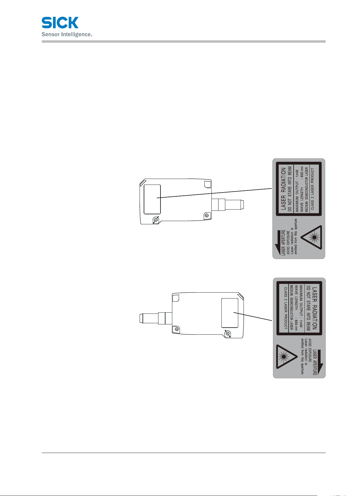
2.4 Warning Labels
Safety Precautions
This section explains the contents and axing position of the warning label
used on this product.
A laser beam is used in the location where this warning label is axed.
Looking directly at the laser beam may lead to loss of eyesight. Be sure
to follow the precautions shown below.
1. Do not look at the laser beam.
2. Do not remove the protective cover.
3. All individuals other than the proper operator must not
approach the product.
EN/IEC 60825-1:2014
Laser radiation – Do not look into the
laser beam – Laser class 2 (EN/IEC
60825-1:2014)
Complies with 21CFR1040.10 and
1040.11 except for deviations pursuant to laser notice No. 50, date June
24, 2007
Identical laser class for issue EN/IEC
60825-1:2007
(IEC 60825-1:2014)
(IEC 60825-1:2014)
8017035/ZMO9/2017-06-08 • © SICK AG • Subject to change without notice. 11
Page 12
Information Before Use
3 Information Before Use
3.1 General Description
The Proler 2 is a high-precision prole measurement sensor.
The characteristics of this product are shown below.
• This product achieves high-precision measurement by emitting a bandshaped laser beam and using a light-plane-intersecting method that
triangulates the reected light.
• Settings can be congured, measurements can be performed,
and output can be generated from the sensor. No amplier unit
or other auxiliary devices are necessary.
• Various settings can be set from the sensor or from the dedicated setup
software (PRO2-navigator).
• It is possible to measure 4 areas with a single measurement. For each
area, there are 13 types of measurement functions to select from.
• There are 4 camera modes available. This enables you to select
the optimum settings to match the environment of the production line
to be measured and the state of the target object.
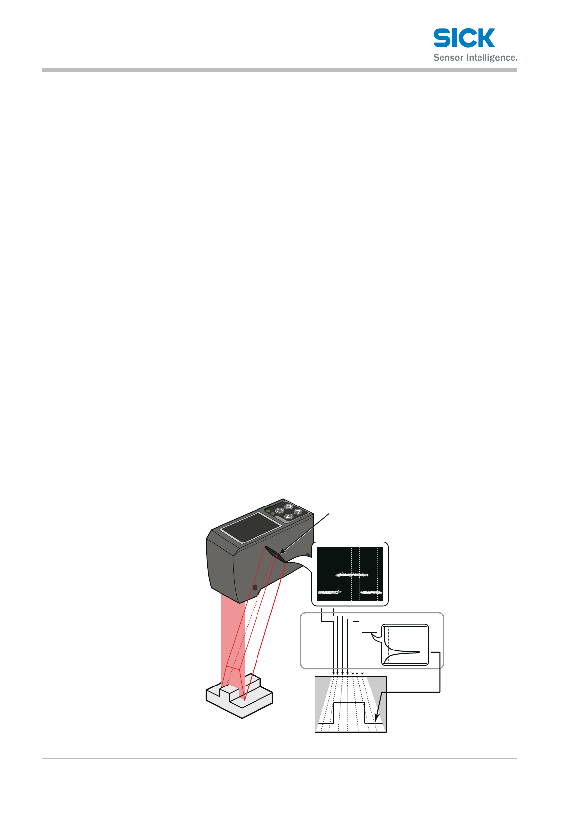
With the light-plane-intersecting method, the reected light from the
emitted band-shaped laser beam is received by the light receiving element
(CMOS), and the prole is then measured from the resulting image data.
With the light-plane-intersecting method, two processes are used to
determine the height and position.
• Triangulation: To determine the height, this process obtains the received
light waveform (the waveform of the reected light) for each vertical line
of the image.
• Projection transformation: To determine the horizontal position,
this process mathematically calculates the actual position from
the image data.
Light recieving element (CMOS)
Image (image data)
Recieved light waveform
Projection
transformation
Prole (distance data)
Figure: Schematic diagram of Proler 2 series measurement
12 © SICK AG • Subject to change without notice. • 8017035/ZMO9/2017-06-08
Page 13

3.2 Package Contents
3.2.1 Included Items
3.2.2 Options
Information Before Use
Before using this product, conrm that the following items are contained
in the package:
• Sensor
• Mounting screws, M4 × 50 mm (2 pieces)
• Quickstart
• Setup software PRO2-navigator and User manual (USB ash drive)
• Laser warning labels (2 pieces)
Prepare the following options as necessary.
Main cable Communication cable
6053017,
STL-0H12-G02M (2 m)
6053018,
STL-0H12-G05M (5 m)
6053019,
STL-0H12-G10M (10 m)
6053020,
DSL-DH06-G1M8 (1.8 m)
(USB)
Communication cable
(discrete wire)
6053021,
DOL-SH06-G02M (2 m)
6053196,
DOL-SH06-G05M (5 m)
6053197,
DOL-SH06-G10M (10 m)
8017035/ZMO9/2017-06-08 • © SICK AG • Subject to change without notice. 13
Page 14
Information Before Use
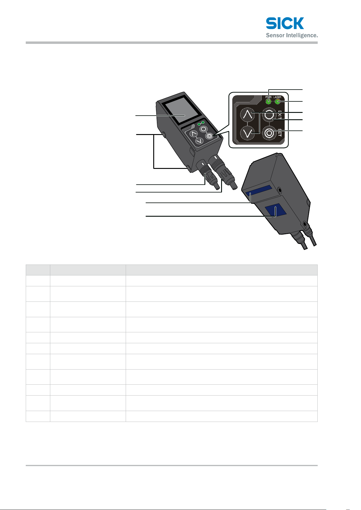
3.3 Names and Functions of Parts
3.3.1 Sensor
7
8
1
2
3
4
5
6
Number Name Function
LCD display This part displays measured results and setting screens.
1
9
ß
à
Mounting holes Screws are inserted into these holes to x the sensor in place.
2
(Diameter: 4.2 mm)
Connector for
3
communi cation cable
Female connector, HRS, 12-
4
pin cable
Sender area, z-axis The laser beam is emitted from this window.
5
Field of view, x-axis The reected laser light is enters this window.
6
LED Indicator for power on
7
(green)
LED Indicator for Laser on
8
(green)
Cursor keys Use these keys to select setting items.
9
EXIT button Press this button to cancel setting details. Hold down this button (> 1 s) to switch
ß
SET button Press this button to conrm setting details.
à
Insert a communication cable into this connector to connect the PC and
the sensor.
Insert the main cable for power, I/O, and analog output into this connector.
This indicator lights when the power is on.
This indicator lights during laser emission.
to the main menu.
14 © SICK AG • Subject to change without notice. • 8017035/ZMO9/2017-06-08
Page 15
Information Before Use
(2.95)
(3.94)
(4.92)
Measuring distance
in mm (inch
(1.26)
h
in mm (inch)
in mm (inch)
(2.95)
(3.94)
(4.92)
Measuring distance
in mm (inch
WARNING
When using the sensor, never look into the laser
exposure window 5. Looking directly at the laser beam
may lead to loss of eyesight.
WARNING
Put the rubber cap on the connector which is not used to
protect from dust and water.
Note!
When using the sensor, do not cover the Sender area 5
or the Field of view 6.
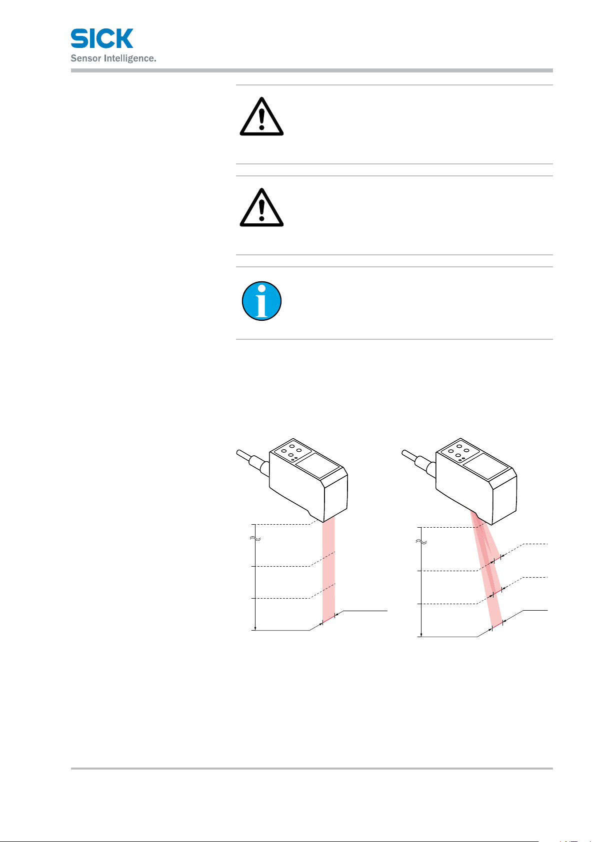
3.3.2 Laser Emission and Measurement Ranges
The sending and receiving area of this product are shown below.
Sending area Receiving area
)
0
75
100
125
Approx. 32
Measuring widt
75
100
125
)
0
17 (0.67)
22 (0.87)
27 (1.06)
Measuring width
8017035/ZMO9/2017-06-08 • © SICK AG • Subject to change without notice. 15
Page 16

Information Before Use
3.3.3 Cable Wire Colors and Roles
This section explains the colors of the wires and the roles of the Proler 2
cables.
Main cable This cable is used to supply power to the Proler 2 and for I/O connections.
Color Input or output Description
Purple Input Bank 1/reset
Orange Input Bank 2/hold
Gray
(narrow)
White Input Oset/stop laser emission
Gray
(coaxial core)
Gray
(coaxial shield)
Green — Ground GND
Yellow Output OUT1
Black Output OUT2
Red Output OUT3
Blue — Power supply GND
Brown — 12 to 24 V input
Input Bank 3/trigger
Output Analog output (4 to 20 mA)
— Analog GND
RS-485 cable This cable is used for RS-485 communication between the Proler 2
and a PLC or similar device.
Color Input or output Description
Orange — +A
Yellow — -A
Black — GND
Red — (N.C.)
Brown — (N.C.)
Green — (N.C.)
Reference: For the I/O circuit diagram, see “9.2 Connection diagram.”
16 © SICK AG • Subject to change without notice. • 8017035/ZMO9/2017-06-08
Page 17
3.4 Installation
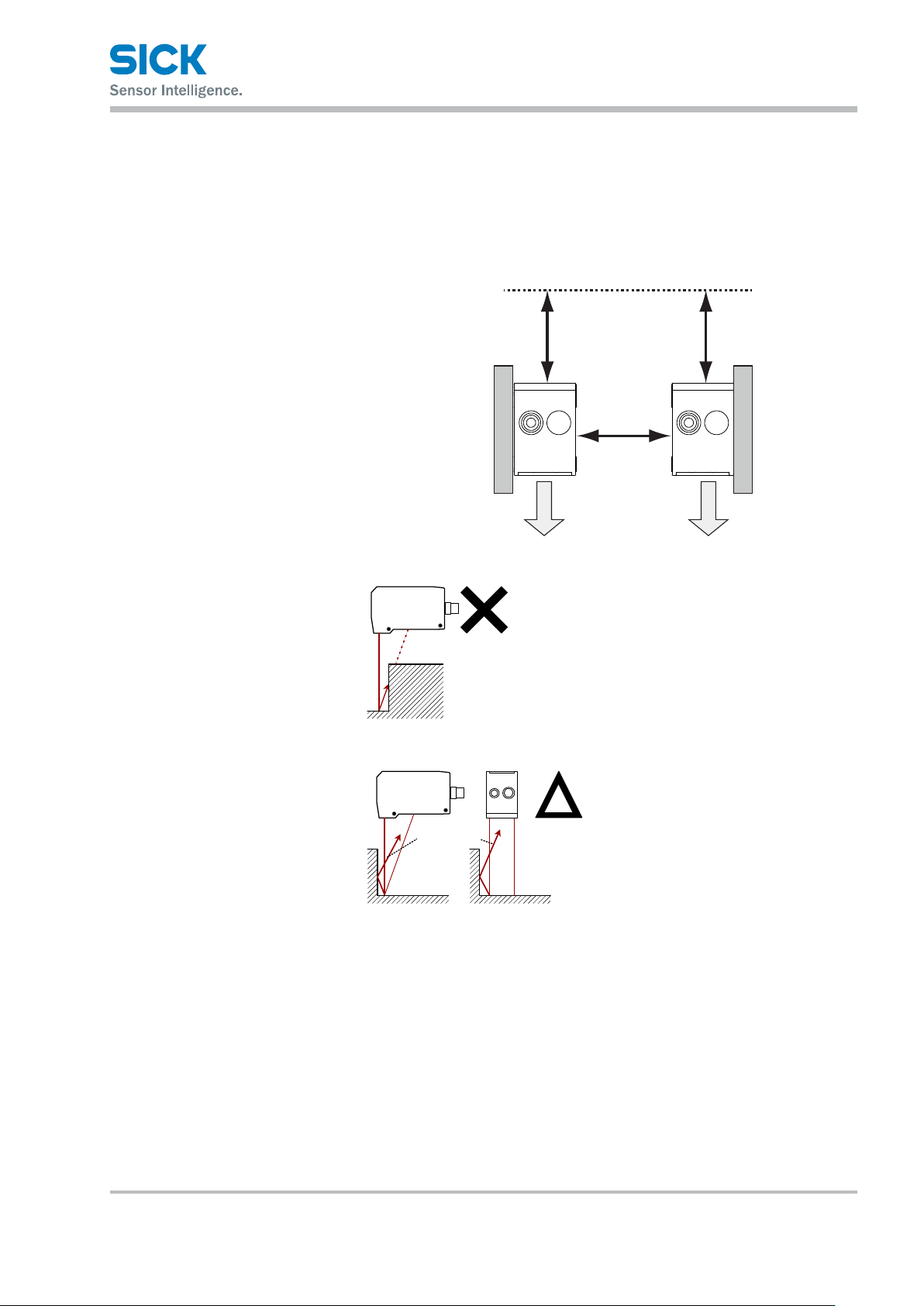
3.4.1 Notes for installation
Information Before Use
When you install this product, ensure that there is sucient space around
the product in order to prevent overheating.
Space required
above the sensor
40 mm or more
Space between sensors
40 mm or more
3.4.2 Installing the Sensor
Laser exposure
direction
迷光
Stray light
Laser exposure
direction
The Proler 2 performs measurements by emitting a parallel laser
beam and receiving the reected
light.
During measurement, ensure that
the laser beam and reected light
is not blocked by the target object.
Before using the product, check
that stray light, which is reected
by a wall or by highly reective
objects, does not have an eect
on the measurements.
1. Insert the included mounting screws (two M4 × 50 mm screws)
into the mounting holes to temporarily ax the sensor to a location
that is roughly in the desired location.
2. Measure the distance between the sensor and the detection
target object. Please make sure the measuring object is within the
measuring area.
3. Adjust the sensor position on the basis of the measurement result,
and then use the included nuts and washers to x the screws in place.
8017035/ZMO9/2017-06-08 • © SICK AG • Subject to change without notice. 17
Page 18

Setup and Measurement Procedures
4 Setup and Measurement Procedures
4.1 BeforeUsingtheProler2
4.1.1 Procedure for Using the Sensor
Before you use the Proler 2, install and setup the sensor according
to the procedure shown below.
1. Installation and light
axis adjustment
2. Wiring Connect the cables.
3. Settings Congure the settings related to measurement. You can use one of the
4. Measurement Perform measurements.
Install the sensor such that you can perform accurate measurements
of the measurement target.
Reference: For details on the installation of the sensor, see “3.4 Installation.”
following methods to congure the settings.
1. Sensor
• Congure all the settings from the Proler 2.
2. PRO2-Navigator
• Use the dedicated PRO2-Navigator setup software to intuitively
view and change all the settings.
3. Serial communication
• Use RS-485 communication to view and change all the settings
of the Proler 2.
With the Proler 2, measurement results can be output using one of the
following methods.
1. Judgment output (control output)
• The Proler 2 is equipped with three judgment outputs (control outputs).
2. Analog current output (4 to 20 mA)
3. Serial communication (RS-485 communication)
4. PRO2-Navigator (monitor display of measured values)
Tips: • Serial communication or PRO2-Navigator is required to output and check
stored data.
18 © SICK AG • Subject to change without notice. • 8017035/ZMO9/2017-06-08
Page 19
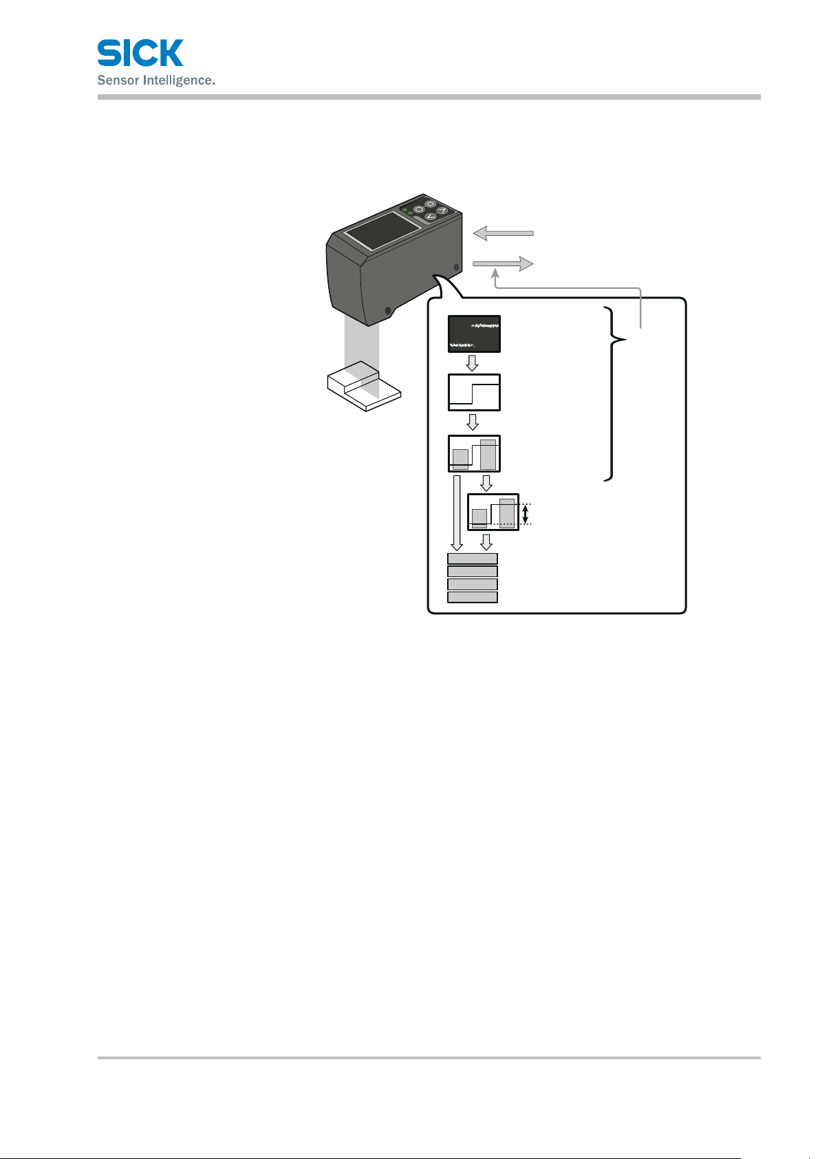
4.1.2 Setup and Measurement Process
The Proler 2 performs measurements according to the following ow.
Settings are also performed for each of these items.
Setup and Measurement Procedures
Laser control input
Trigger signal
Judgment output (control output)
Analog output
Camera imaging
Camera settings
Profile
Profile settings
Area measurement
Area settings
Output is
stopped
during
settings.
Area calculation
Calculation settings
Out 1
Out 2
Out 3
Analog
Result judgment and output
Output settings
1. Trigger
• Images are captured when the set conditions are met.
2. Camera
• An image is captured based to the settings.
3. Prole acquisition
• The prole (the sectional prole made by the reected laser light)
is acquired from the image.
4. Area measurement
• The specied position within the prole is measured.
5. Area calculation
• If necessary, the measured result of the area is calculated. e. g. Area
1 – Area 2 = Calc 1)
6. Result judgment and output
• The measured result is compared against the threshold, and then the
judgment result is output.
Tips: • With the Proler 2, you can save settings related to measurements
in “banks.” Up to eight banks can be saved.
Reference: For details on banks, see “7.9.1 Banks.”
8017035/ZMO9/2017-06-08 • © SICK AG • Subject to change without notice. 19
Page 20

Setup and Measurement Procedures
4.2 Quick Setup
4.2.1 Basic Measurement Settings
You can take basic measurements simply by setting the following three
items. Congure the settings from the sensor or from the PRO2-Navigator
setup software.
• Shutter time
• Area
• Output conditions
Reference: For the actual screens and for information on the operations,
see the following pages.
Conguring settings from the sensor
Using PRO2-Navigator
1. Set the shutter time Position the measurement target, and then perform automatic adjustment.
The optimum shutter time will be set.
→ “6.3 PRO2-Navigator Screen and Operating.”
→ “5.3 Setting.”
2. Set the area Use the area setting to specify what part you will measure and how that
part will be measured.
1. Measurement area
• Set what part within the measurement range will be measured.
The set area must intersect the prole (the sectional waveform).
2. Measurement function
• Set the measurement function. You can select from functions
such as height and width.
Reference: For details on the area settings, see “7.6 Area Settings.”
3. Set the output conditions Congure the settings related to the output of the measured results.
First, specify the judgment and output target area.
• Output target
Select the target area (area 1 to area 4 and calculation 1 and
calculation 2).
1. Measurement output
The product judges whether the measurement is a pass or a fail,
and then outputs the result.
• Upper limit/lower limit
2. Analog current output (4 to 20 mA)
• 4 mA/20 mA
Set the lower and upper limits of the analog output range.
20 © SICK AG • Subject to change without notice. • 8017035/ZMO9/2017-06-08
Page 21
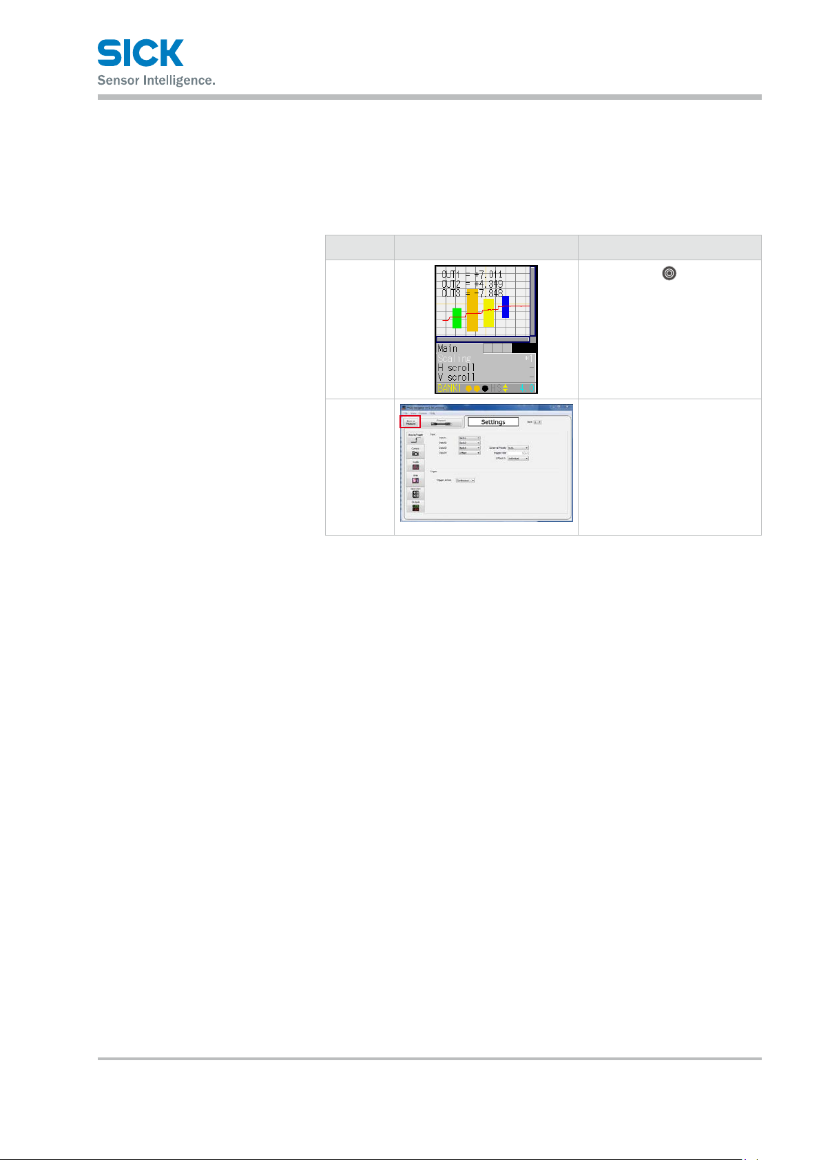
4.2.2 Return to Main Menu/Measurement Screen
When you have nished conguring settings or when you are not sure what
menu you are currently on, you can follow the procedures below to return
to the main menu (the measurement screen).
Related page
Screen image Operation
Setup and Measurement Procedures
Sensor
screen
Setup
software
Hold down the “EXIT” button.
* For the “In/Trig” and “Other”
tab, you need to select the tab,
and then hold down the “SET”
button to return to the main
menu.
Click “Back to Measure.”
8017035/ZMO9/2017-06-08 • © SICK AG • Subject to change without notice. 21
Page 22
Setup and Measurement Procedures
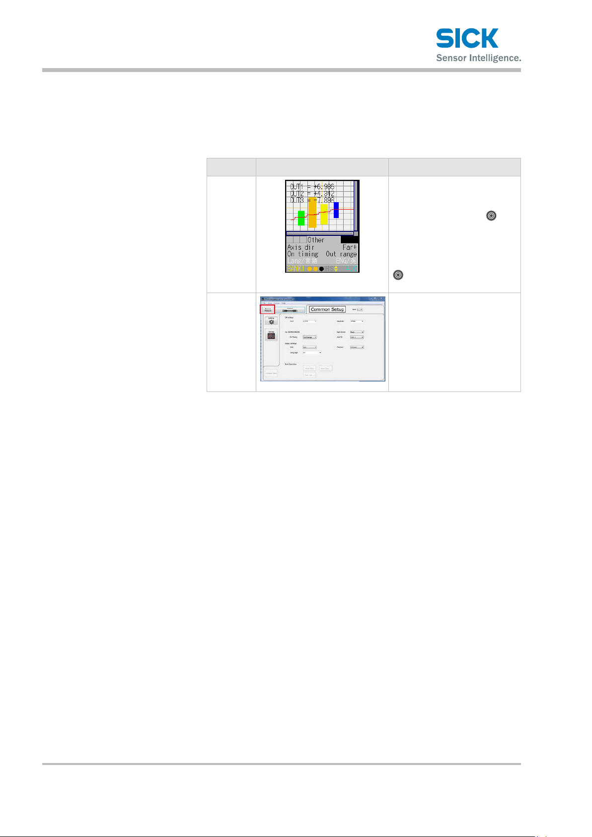
4.2.3 Initialize Settings
This section describes how to initialize settings.
You can initialize one bank at a time or all banks at the same time.
Related page
Screen image Operation
Sensor
screen
Setup
software
Tips: • If you select “All” on the initialization menu, the Proler 2 will restart.
To initialize settings, on the
“Other” tab, display the “Initialize” menu, select “Bank” or
“All,” and then press the
“SET” button.
When the conrmation screen
displays the message “Reset to
factory initial value.,” press the
“SET” button again to execute
initialization.
On the measurement screen,
click “Common Setup.” The
Common Setup screen displays.
Click the target that you want to
initialize, and click “Bank Clear.”
A conrmation dialog displays.
Click “Yes” to execute initialization.
22 © SICK AG • Subject to change without notice. • 8017035/ZMO9/2017-06-08
Page 23
5 Operating the Sensor
5.1 Sensor Screen
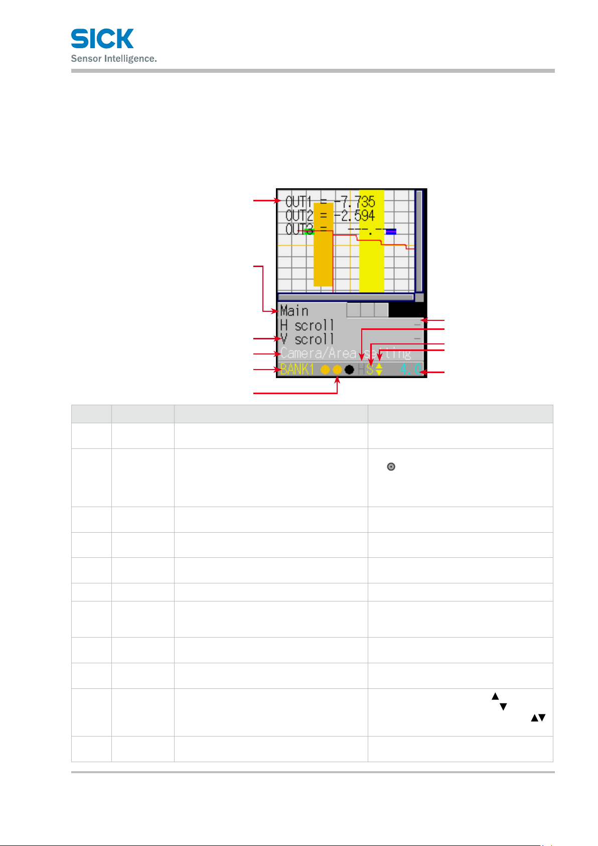
5.1.1 Details of the Screen
This section explains the details of the screen display.
1
2
3
4
6
Operating the Sensor
5
8
9
ß
à
7
Number Display item Description Operation
Main screen The camera screen, prole waveform, and set
1
area are displayed here.
Tab The menu categories are displayed here.
2
You can also select this part.
Setting menu The setting menu is displayed here.
3
Three settings are displayed at one time.
Setting menu
4
(selected)
Parameter The parameters for the settings are displayed
5
Bank number The current bank number is displayed here. —
6
Output The control output statuses are displayed here
7
Hold input When the input is being held, an “H” is
8
Storage func-
9
tion
Cursor/Key
ß
Lock
Sampling
à
period
When a setting is selected, the color changes. When selected: White
here.
in the order – from the left – control output 1,
control output 2, control output 3.
displayed here.
The storage function operation status is displayed here.
A cursor that indicates the direction that
the screen can move in is displayed here or a "L"
that indicates the activated key lock.
The sampling period is displayed here.
The unit is “ms.”
—
Move the cursor to the tab, and then press
the
“SET” button to switch between the
tabs in order.
When not selected: Black
When selected: Blue
—
When setting the para meter: Yellow
When item selected: White
When setting the para meter: Yellow
When output is o: Black
When output is on: Orange
When input is being held:
“H” displayed in yellow
Trigger standby: Green
Storing: Yellow
When the screen can move up:
When the screen can move down:
When the screen can move up and down:
When the keys are locked: L
—
8017035/ZMO9/2017-06-08 • © SICK AG • Subject to change without notice. 23
Page 24
Operating the Sensor
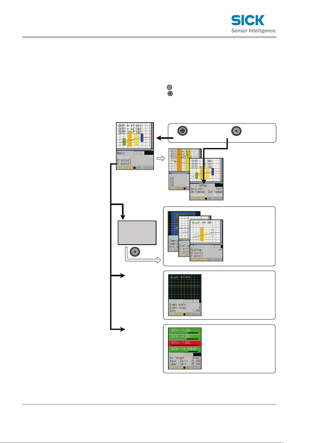
5.1.2 Screen Types and Switching Between Screens
This section explains the types of screens and how to switch between
the screens.
The following screens are available on the Proler 2.
You can switch between screens by selecting the screen on the main
screen or by pressing the “SET” button with the tab selected.
Also, if you hold down the “EXIT” button on any screen, you will return
to the main screen. (Excluding the “Input/Trigger” and “Other” screens.)
Common operations
●
EXIT
Switch to the
Main screen
Hold down for 1 sec. or more
●When a tab is selected
SET
Select tab
In/Trig setting
Storage setting
Other setting
Switch from
the menu.
Setting
Output will be
stopped and go
to setup window.
Y:[SET] / N:[EXIT]
Graph/Calc
Setting
Output
Setting
Camera setting
Profile setting
Area setting (1 to 4)
SET
Area graph
Calc graph/setting
Output setting
24 © SICK AG • Subject to change without notice. • 8017035/ZMO9/2017-06-08
Page 25
5.1.3 Key Lock Function
Operating the Sensor
Key Lock is available to prevent miss-operation. It can be activated or
released by pressing buttons.
• Activate Key Lock
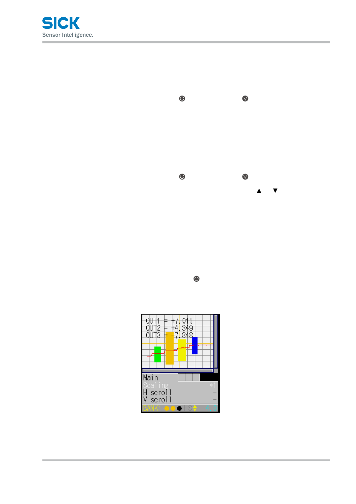
5.2 Main Screen
5.2.1 Main
Hold down the
for 3 seconds.
While keys are locked, the cursor shows as "L".
• Operation while Key Lock is activated
When any keys are pressed while Key Lock is activated, following message
will be shown.
"KEY LOCK You can not operate without unlock"
Setting through communication I/F is available while Key Lock is activated.
• Release Key Lock
Hold down the
for 3 seconds.
While keys are released, the cursor shows as " " or " "..
This section explains the items that can be selected on the main screen
and the operations of these items.
Table items marked in the following table with “Y”(= Yes) in the “Bank”
column can be set for each bank. In the same manner, items that have an
“N” (= No) for their bank are shared between all banks.
"EXIT" button and the "Down Cursor" button at a time
"EXIT" button and the "Down Cursor" button at a time
If you hold down the “EXIT” button on any screen, you will return
to this screen.
(Excluding the “Input/Trigger” and “Other” screens.)
You can switch to each other screen from this screen.
8017035/ZMO9/2017-06-08 • © SICK AG • Subject to change without notice. 25
Page 26
Operating the Sensor
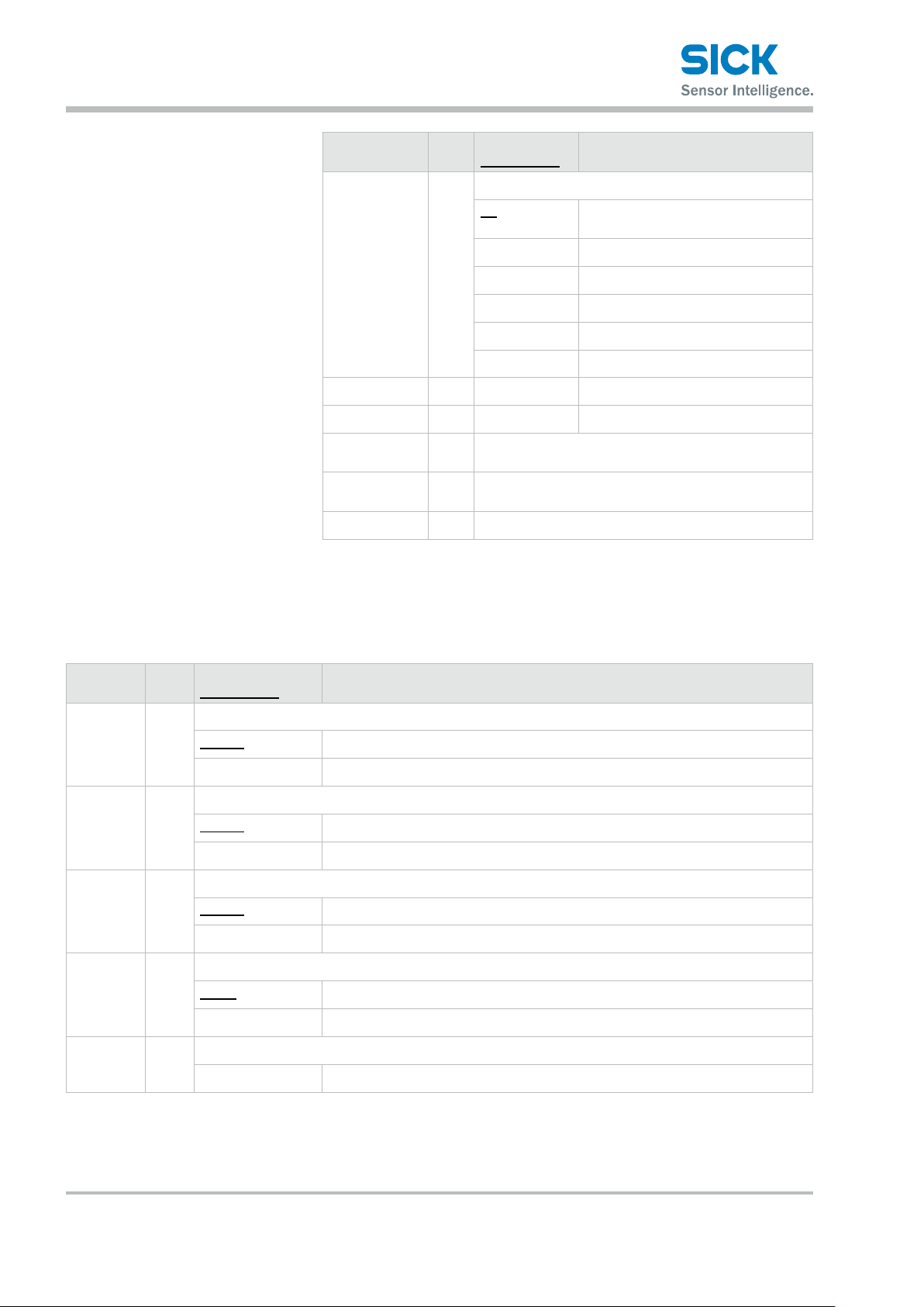
5.2.2 Input/Trigger
Setting item Bank Setting value/
default value
Scaling Y
H scroll Y — Move the display position horizontally.
V scroll Y — Move the display position vertically.
Camera/
Area setting
Graph/
Calc setting
Output — Switch to the output display/setting screen.
— Switch to the setting screen.
— Switch to the calculation setting screen. The measured
Expand or shrink the display range.
*1 Display at 100% size. The whole
*2 Display at 200% size.
*4 Display at 400% size.
*8 Display at 800% size.
*16 Display at 1600% size.
*32 Display at 3200% size.
result will be displayed as a graph.
General description
range will be displayed.
Set the operation of the input terminals and of the camera start trigger.
Setting
item
IN1 N
IN2 N Set the behavior of external input terminal IN2.
IN3 N Set the behavior of external input terminal IN3.
IN4 N Set the behavior of external input terminal IN4.
Reset — Execute the reset operation.
Bank Setting value/
default value
Set the behavior of external input terminal IN1.
BANK1 IN1 is used as the rst bit for switching banks.
Reset IN1 is used as the reset input terminal.
BANK2 IN2 is used as the second bit for switching banks.
Hold IN2 is used as the hold input terminal.
BANK3 IN3 is used as the third bit for switching banks.
Tri g ger IN3 is used as the trigger input terminal.
Oset IN4 is used as oset input.
LaserOFF IN4 is used as the laser emission stop input.
General description
Wait...
This is displayed when the reset operation is being executed.
26 © SICK AG • Subject to change without notice. • 8017035/ZMO9/2017-06-08
Page 27
Operating the Sensor
Setting
item
Inner hold — Each time that the SET button is pressed, the hold function will be turned on or o.
Inner trig — Each time that the SET button is pressed, the trigger will be turned on or o.
Input polar N Set the operation polarity of the external input terminals.
Trig action Y Set the measurement operation to perform when trigger input is received.
Trig count Y Set the count to use when “Trig action” is set to “Count.” The condition to enable this function is:
Bank Setting value/
default value
The condition to enable this function is: IN2: BANK2.
OFF
ON
The condition to enable this function is: IN3: BANK3.
N.O. The trigger turns on when input is applied.
N.C. The trigger turns o when input is applied.
N.O. The trigger turns on when input is applied.
N.C. The trigger turns o when input is applied.
Cont Measurements will be performed continuously.
1shot One measurement will be performed when trigger input is received.
Count When the predetermined number of trigger inputs are received,
Trig action: Count.
1 to 4095 [1] [Unit: Number of times]
General description
one measurement will be performed see Trig count.
Inp lter N Set the external input lter time to prevent chattering.
5 to 1275 [5] [Unit: μs] * You can set this value
in steps of 5 μs.
Trig delay Y Set the delay time between the trigger meeting the camera conditions and the camera actually taking
images.
5 to 20475 [5] [Unit: μs] * You can set this value in steps of 5 μs.
Oset
target
N Select the target on which to execute the oset.
The condition to enable this function is: IN4: Oset.
Indivi Depending on the input time, the oset will be executed on or cleared from
OUT1, OUT2, or OUT3 or on all of these.
All The oset will be executed on or cleared from all of OUT1, OUT2, and OUT3.
OUT1 The oset will be executed on or cleared from OUT1.
OUT2 The oset will be executed on or cleared from OUT2.
OUT3 The oset will be executed on or cleared from OUT3.
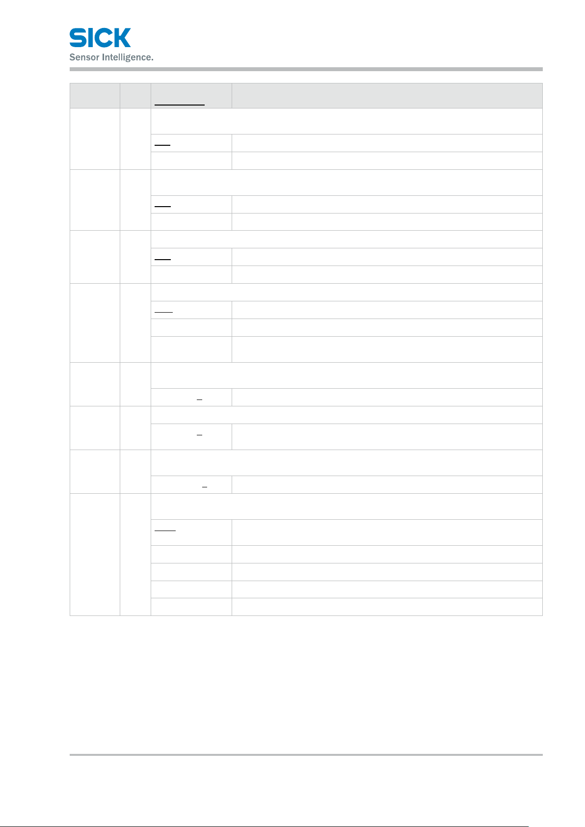
5.2.3 Storage
Congure the settings related to the storage function.
Serial communication or PRO2-navigator is required to check stored data.
8017035/ZMO9/2017-06-08 • © SICK AG • Subject to change without notice. 27
Page 28
Operating the Sensor
Setting
item
Storage N
No.of Data N Set the number of data saved starting from the start position.
Start cond N Used to select storage start conditions.
Start pos N Set the storage start position for the trigger.
Bank Setting value/
default value
Select data for storage.
OFF Storage not performed.
Measure Stores measurement values.
Prole Stores prole and measurement values.
1 to 65535 [1000] The upper limit is 8000 when storing a prole.
Continue Storage always executed.
Hold in Starts storage operation on a Hold start of the external input terminal.
Measure Storage starts from the point that the specied measurement target becomes
Alarm Storage starts from the instant that the specied measurement target becomes
UP limit Storage starts from the point that the specied measurement target exceeds the
LOW limit Storage starts from the point that the specied measurement target falls below
General description
measurable.
not measurable.
threshold.
the threshold.
-10000 to +10000
[0]
Start target N Used to select the target of the storage start condition.
The condition to enable this function is: Start cond: Measure, Alarm, UP limit, or LOW limit
Area1
Area2 Storage starts based on an area 2 value.
Area3 Storage starts based on an area 3 value.
Area4 Storage starts based on an area 4 value.
Calc1 Storage starts based on a calculation 1 value.
Calc2 Storage starts based on a calculation 2 value.
Threshold N Set the threshold when "UP limit" or "LOW limit" is selected for "Start cond".
The condition to enable this function is: Start cond: UP limit, LOW limit
-999.999 to
+999.999 [0]
Intermittent
N Data storage interval. All data is stored when the setting value is "0".
0 to 8191 [10]
[Unit: Number of samplings]
Using 0 as reference, a negative value indicates a previous position (pre-trigger)
while a positive value indicates a subsequent position (delay trigger). When the
storage target is prole, the value can be set in a range of -2000 to +2000.
Storage starts based on an area 1 value.
[Unit: Number of samplings]
28 © SICK AG • Subject to change without notice. • 8017035/ZMO9/2017-06-08
Page 29

Operating the Sensor
Setting
item
Repeat N Set the behavior when the number of storage data items reaches the upper limit.
Reference: For details on the camera settings, see “7.3 Storage Settings.”
Bank Setting value/
default value
ON Returns to the top and updates data, overwriting with the new data.
OFF Storage stops at the point that the upper limit value is reached.
Pause When the storage start condition is met, storage starts up to the limit and hold
General description
The storage target automatically changes to "OFF".
until the start condition is met and so on.
Once after storing up to the limit, it overwrite with new data.
8017035/ZMO9/2017-06-08 • © SICK AG • Subject to change without notice. 29
Page 30

Operating the Sensor
5.2.4 Other
Setting
item
Bank
switch
Bank N
Bank Setting value/
default value
N Select how to change between banks.
In/Para Sensor operations or the input terminals will be used to change between banks.
Comm Communication (including PRO2-Navigator) will be used to change between banks.
Change the bank. The display details vary depending on the settings of the input terminals.
The bank is determined by the details of this setting and the status of the input terminals.
The condition to enable this function is: Bank switch: In/Para.
Input terminal
settings
— You cannot switch the bank from
Input terminal
settings
1, 3, 5, 7 The bank is changed to number 1, 3, 5, or 7.
2, 4, 6, 8 The bank is changed to number 2, 4, 6, or 8.
Input terminal
settings
1, 5 The bank is changed to number 1 or 5.
General description
IN1: BANK1
IN2: BANK2
IN3: BANK3
the sensor.
Reset
IN2: BANK2
IN3: BANK3
IN1: Reset
IN2: Hold
IN3: BANK3
2, 6 The bank is changed to number 2 or 6.
3, 7 The bank is changed to number 3 or 7.
4, 8 The bank is changed to number 4 or 8.
Input terminal
settings
1, 2, 3, 4 The bank is changed to number 1, 2, 3, or 4.
5, 6, 7, 8 The bank is changed to number 5, 6, 7, or 8.
Input terminal
settings
1, 3 The bank is changed to number 1 or 3.
2, 4 The bank is changed to number 2 or 4.
5, 7 The bank is changed to number 5 or 7.
6, 8 The bank is changed to number 6 or 8.
Input terminal
settings
1, 2 The bank is changed to number 1 or 2.
3, 4 The bank is changed to number 3 or 4.
IN1: BANK1
IN2: BANK2
IN3: Trigger
IN1: Reset
IN2: BANK2
IN3: Trigger
IN1: BANK1
IN2: Hold
IN3: Trigger
30 © SICK AG • Subject to change without notice. • 8017035/ZMO9/2017-06-08
Page 31

Operating the Sensor
Setting
item
Baud rate N Select the communication baud rate.
Bank Setting value/
default value
5, 6 The bank is changed to number 5 or 6.
7, 8 The bank is changed to number 7 or 8.
Input terminal
settings
1 The bank is changed to number 1.
2 The bank is changed to number 2.
3 The bank is changed to number 3.
4 The bank is changed to number 4.
5 The bank is changed to number 5.
6 The bank is changed to number 6.
7 The bank is changed to number 7.
8 The bank is changed to number 8.
9.6K 9,600 bps
19.2K 19,200 bps
General description
IN1: Reset
IN2: Hold
IN3: Trigger
38.4K 38,400 bps
57.6K 57,600 bps
115K 115,000 bps
230K 230,000 bps
460K 460,000 bps
921K 921,000 bps
2.0M 2.0 Mbps
4.0M 4.0 Mbps
Axis dir N Set the increase/decrease direction of the measured value height with the measurement center
set as 0 mm.
Near+ Set the side close to the head as positive (+).
Far+ Set the side far from the head as positive (+).
On Timing N Set either within range or outside of range (as specied by the thresholds) as output judgment criteria.
Out range Output turns on when the value is outside the range specied by the threshold.
In range Output turns on when the value is within the range specied by the threshold.
Lang/言語 N Select the screen’s display language.
JPN/日 Information will be displayed in Japanese.
ENG/英 Information will be displayed in English.
8017035/ZMO9/2017-06-08 • © SICK AG • Subject to change without notice. 31
Page 32

Operating the Sensor
Setting
item
Screensaver
Brightness N
Initialize — Initialize the setting values to their factory default values.
Version — Display the version of the sensor. (This information is only displayed.)
Bank Setting value/
default value
N Select the behavior of the display after 30 seconds without any operation.
Dark Make the display backlight dark.
LCD O Turns OFF the display backlight. While the display backlight is OFF, the communi-
0 to 15 [15] Adjust the screen’s brightness.
All Initialize the setting values of all banks and the common settings.
Bank Initialize the setting values of the currently selected bank.
General description
cation speed will get faster.
When you execute this operation, the sensor will automatically restart.
5.3 Setting
This section explains the setting items on the setting screen.
The setting screen has three sets of settings:
“Camera,” “Prole,” and “Area.”
While the setting screen is displayed, judgment output (control output)
is stopped and out-of-range analog current output is generated
(approximately 24 mA).
Table items marked with “Y” in the “Bank” column can be set for each
bank. In the same manner, items that have an “N” for their bank are
shared between all banks.
5.3.1 Camera
Use the camera settings to congure camera (sampling) conditions such as
the camera mode, the camera area, and the exposure condition in order to
match the measurement target and environment.
Camera screen
Camera items You can use the camera settings to congure the following items.
32 © SICK AG • Subject to change without notice. • 8017035/ZMO9/2017-06-08
Page 33

Operating the Sensor
Setting
item
Camera
mode
Camera
range
Auto adjust — Performs an automatic adjustment to set the shutter time to the optimum value.
Gain Y Specify the light reception gain. The larger the number, the higher the gain.
Bank Setting value/
default value
Y
Select the camera mode.
Hi-res All of the pixels will be used by the camera.
Hi-spd Image capture time is reduced to 1/4 of the time in Hi-res mode.
HDR Screens captured by the camera at two dierent shutter speeds will be
NR This function eliminates noise by capturing an image with the laser on and
Y Sets the camera range.
The narrower the range, the shorter the imaging time and the sampling period become.
-— [Entire area]
Before you perform the automatic adjustment, set the actual measurement target in place,
and do not move the target during the adjustment.
When you execute automatic adjustment, “Camera mode” will automatically change to “Hi-res.”
Wait... Displays while automatic adjustment is being executed.
General description
Image acquisition time: 5 ms (with the maximum image area)
Resolution is reduced by half in both the horizontal and vertical directions.
Image capture time: 1.25 ms (maximum image area)
combined. This enables stable measurements of parts that are highly reective
or that are minimally reective.
another image with the laser o, and then determining the dierences between
the images.
1.00 Minimum gain
1.14
1.33
1.60
2.00
2.29
2.67
3.20
4.00
5.33
8.00 Maximum gain
Shutter Y Set the shutter time.
5 to 10235 [500] [Unit: μs] * You can set this value in steps of 5 μs.
HDR
shutter
Y The condition to enable this function is: Camera mode: HDR.
Sets the shutter speed to use when “Camera mode” is set to “HDR.”
This must be set to a value that is greater than the “Shutter” setting value (so that the shutter time
is longer).
When you set “Camera mode” to “HDR,” this is set to a value that is (shutter time × 4).
5 to 10235 [1000] [Unit: μs] * You can set this value in steps of 5 μs.
8017035/ZMO9/2017-06-08 • © SICK AG • Subject to change without notice. 33
Page 34

Operating the Sensor
Setting
item
Threshold Y Set the threshold (lower limit) of the light amount at which an alarm is triggered
Reject
level
Reference: For details on the camera settings, see “7.3 Storage Settings.”
Bank Setting value/
default value
* Normally you do not have to change this setting.
0 to 255 [32] [Unit: Received light amount]
Y Set the ratio to exclude when performing calculations from the received light waveform.
* Normally you do not have to change this setting.
0 to 127 [16] [No unit: (n + 1)/128]
General description
34 © SICK AG • Subject to change without notice. • 8017035/ZMO9/2017-06-08
Page 35

5.3.2 Prole
Operating the Sensor
Use the prole settings to congure the conditions for extracting proles
from the camera images.
Also, when using the prole position, height, and tilt correction,
set correction conditions.
Prolescreen
Height correction
reference position
(purple line)
Position correction
reference height
(blue line)
Tilt correction
reference position
(green line)
Proleitems You can use the prole settings to congure the following items.
Setting
item
Scaling Y
Bank Setting value/
default value
Expand or shrink the display range.
*1 Display at 100% size. The whole range will be displayed.
General description
*2 Display at 200% size.
*4 Display at 400% size.
*8 Display at 800% size.
*16 Display at 1600% size.
*32 Display at 3200% size.
H scroll Y -— Move the display position horizontally. When the display range is at 100% size,
you cannot move the display position.
V scroll Y Wait... Move the display position vertically. When the display range is at 100% size,
you cannot move the display position.
Tar get Y Select the measurement target.
Normal The standard setting to perform measurements.
Gap Select this setting when the target has large level dierences.
The level dierence edge precision will be improved.
Semi-trans Use this setting when you are measuring resin or other semi-transparent objects.
8017035/ZMO9/2017-06-08 • © SICK AG • Subject to change without notice. 35
Page 36

Operating the Sensor
Setting
item
Alarm limit Y Set the number of values (measured values to the right) to maintain when an alarm occurs.
Smoothing Y This function averages the prole in the horizontal (X-axis) direction to make the waveform smoother.
Correct
method
Bank Setting value/
default value
When you specify this setting, the specied number of values immediately before the alarm (to the
right) will be maintained.
If alarms occur repeatedly such that the set number of values is exceeded, an alarm (measured value
7FFF) is triggered.
0 to 14/HOLD [6] [Unit: Number of values] * HOLD: Alarm state is not entered.
[Unit: Number of measurements]
1 Averaging will not be performed.
2
4
8
16
32
64
128
Y Select the correction method.
To use this function, you have to perform master image registration. Also, when you change this setting,
you have to update the master image.
- Correction will not be performed.
General description
→
←
→
↑
←
↑
↑
H correct Y The position of the area at the specied height will be corrected by the dierence between the master
image and the measured prole.
To use this function, you have to perform master image registration. Also, when you change this setting,
you have to update the master image.
-28000 to +28000
[0]
V correct Y The height of the area at the specied position will be corrected by the dierence between the master
image and the measured prole.
To use this function, you have to perform master image registration. Also, when you change this setting,
you have to update the master image.
The condition to enable this function is: Correct method: ↑→, ↑←, or ↑.
-15000 to +14998
[-6500]
Tilt correct Y The prole tilt will be corrected so that the two specied points become level with each other.
ON/OFF —
Position correction will be performed on the basis of the left side.
Position correction will be performed on the basis of the right side.
Height correction will be performed, and then position correction (left side)
will be performed.
Height correction will be performed, and then position correction (right side)
will be performed.
Height correction will be performed.
[Unit: X coordinate] * You can set this value in steps of 2.
[Unit: Y coordinate] * You can set this value in steps of 2.
36 © SICK AG • Subject to change without notice. • 8017035/ZMO9/2017-06-08
Page 37

Operating the Sensor
Setting
item
Tilt cor pos Y Set the reference position of the second point to use in tilt correction.
Save
master
Reference: For details on the prole settings, see “7.5 Prole Settings.”
Bank Setting value/
default value
The reference position of the rst point is the “H correct” reference position.
To use this function, you have to perform master image registration. Also, when you change this setting,
you have to update the master image.
The condition to enable this function is: Tilt correct: ON.
-14998 to +15000
[0]
— Register the current prole as the master image.
Wait... This is displayed when the prole is being registered as the master image.
General description
[Unit: X coordinate] * You can set this value in steps of 2.
8017035/ZMO9/2017-06-08 • © SICK AG • Subject to change without notice. 37
Page 38

Operating the Sensor
5.3.3 Area
Area screen
To switch to the Area screen, select the tab in measurement mode,
and then press the “SET” button.
Area items You can use the area settings to congure the following items.
Setting
item
Scaling Y
H scroll Y -— Move the display position horizontally. When the display range is at 100% size,
V scroll Y -— Move the display position vertically. When the display range is at 100% size,
Coverage Y -— Set the range of the area.
Meas func Y Select the measurement function of the area. The unit is [mm] unless stated otherwise.
Bank Setting value/
default value
Expand or shrink the display range.
*1 Display at 100% size. The whole range will be displayed.
*2 Display at 200% size.
*4 Display at 400% size.
*8 Display at 800% size.
*16 Display at 1600% size.
*32 Display at 3200% size.
Average The average of the measured values within the area will be output.
General description
you cannot move the display position.
you cannot move the display position.
P height The largest measured value within the area will be output.
B height The smallest measured value within the area will be output.
Width The width of the prole that crosses the center of the area will be output.
P pos The position of the largest measured value within the area will be output.
B pos The position of the smallest measured value within the area will be output.
38 © SICK AG • Subject to change without notice. • 8017035/ZMO9/2017-06-08
Page 39

Operating the Sensor
Setting
item
Edge dir H Y Set the direction in which edges will be detected during the “Edge pos” measurement.
Direction Y Set the direction in which to perform measurements during the “Size” and “Diameter” measurements.
Inect
threshold
Correction Y Select whether to use the set position and height correction with this area.
Bank Setting value/
default value
Edge pos The position at which the prole crosses the center of the area will be output.
EdgeCount The number of times that the prole crosses the center of the area will be output.
Tilt A straight line approximating the prole will be determined, and then the tilt
Size The mathematical area of the section bounded by the prole and the area will be
Length The line length of the prole will be determined.
Diameter A circle approximating the prole will be determined, and then the diameter
Inect The position of the point which is inecting most will be output.
The condition to enable this function is: Meas func: Edge pos.
←
→
The condition to enable this function is: Meas func: Size or Diameter.
↑
↓
Y Set the threshold value. When detecting inecting point, it outputs when the inection reaches to this
value. The condition to enable this function is: Meas func: Inect
↓-255 ~ +255
[+3]
General description
[Unit: Number of times]
of this line will be measured.
[Unit: Degrees (°)] * Slope rising to the right will be treated as positive.
determined.
[Unit: mm2]
of this circle will be output.
Positions will be detected from the right side.
Positions will be detected from the left side.
The mathematical area will be measured from the lower side of the area up.
Diameter measurements will be made with the top part of the circle as convex.
The mathematical area will be measured from the top side of the area down.
Diameter measurements will be made with the lower part of the circle as convex.
The polarity means direction of the inection.
OFF The position and height correction will not be used.
ON The position and height correction will be used.
Reference: For details on the area settings, see “7.6 Area Settings.”
8017035/ZMO9/2017-06-08 • © SICK AG • Subject to change without notice. 39
Page 40

Operating the Sensor
5.4 Graph/Calc
Graph/Calc screen
The measured results of each area are displayed as a graph.
You can also set calculation functions for adding or subtracting area
measured results.
You can set up to two calculation formulas in the format (calculation
target 1) (operator) (calculation target 2).
Example: If calculation target 1 is “area 1,” calculation target 2 is “area 2,”
and the operator is “+,” the calculation formula will be:
(area 1) + (area 2).
Table items marked with “Y” in the “Bank” column can be set for each
bank. In the same manner, items that have an “N” for their bank are
shared between all banks.
Reference: See “7.7 Calculation Settings.”
40 © SICK AG • Subject to change without notice. • 8017035/ZMO9/2017-06-08
Page 41

5.4.1 Graph Items (Area 1 to area 4)
You can use the graph display settings to congure the following items.
Operating the Sensor
Setting
item
Graph
scale
Graph
range
Span Y Set a span (multiplier) on the measured values.
Average Y Set the number of times over which to perform the moving average of the measured values.
Hold Y Select the measured result hold operation.
Reference: For details on the graph display settings, see “7.7 Calculation Settings.”
Bank Setting value/
default value
Y
Expand or shrink the display time axis (the horizontal axis).
1 to 6 [1]
Y Expand or shrink the measured value display range (the vertical axis).
0 to 6 [0]
0.001 to 1.999
[1.000]
1 to 1023 [32] [Unit: Number of times]
None The measured result will be output as-is. (Hold input will be ignored.)
Sample The measured value during hold input will be output.
Peak The maximum value during the hold input period will be output.
Bottom The minimum value during the hold input period will be output.
General description
8017035/ZMO9/2017-06-08 • © SICK AG • Subject to change without notice. 41
Page 42

Operating the Sensor
5.4.2 Calc Items (Calculation 1 and calculation 2)
You can use the area calculation settings to congure the following items.
Setting
item
Graph
scale
Graph
range
Span Y Set a span (multiplier) on the measured values.
Hold Y Select the measured result hold operation.
Calc
target1
Bank Setting value/
default value
Y
Expand or shrink the display time axis (the horizontal axis).
1 to 6 [1]
Y Expand or shrink the measured value display range (the vertical axis).
0 to 6 [0]
0.001 to 1.999
[1.000]
None The measured result will be output as-is. (Hold input will be ignored.)
Sample The measured value during hold input will be output.
Peak The maximum value during the hold input period will be output.
Bottom The minimum value during the hold input period will be output.
Y Select the area for calculation target 1.
Area1
Area2
Area3
General description
Area4
Operator Y Select the operator of the calculation formula.
+ Calculation target 1 + calculation target 2
- Calculation target 1 - calculation target 2
Calc
target2
Reference: For details on the graph display settings, see “7.7 Calculation Settings.”
Y Select the area for calculation target 2.
Area1
Area2
Area3
Area4
42 © SICK AG • Subject to change without notice. • 8017035/ZMO9/2017-06-08
Page 43

5.5 Output
Operating the Sensor
Use the output display to view the current output status and to set
the judgment and analog outputs.
Table items marked with “Y” in the “Bank” column can be set for each
bank. In the same manner, items that have an “N” for their bank are
shared between all banks.
Output screen
When within the range specied by the thresholds: Green
When outside the range specied by the thresholds: Red
When the measured value is within the range specied
by the thresholds, the bar graph indicates the position of
the measured value in relation to the thresholds.
Tips: • The background colors of the output screen indicate the judgment
results corresponding to the current measured results.
• The output display in the lower part of the screen indicates the current
output status, so the background color and the output color may not
match.
8017035/ZMO9/2017-06-08 • © SICK AG • Subject to change without notice. 43
Page 44

Operating the Sensor
5.5.1 Output Items (OUT1 to OUT3)
When the OUT1, OUT2, or OUT3 tab is selected, you can use the output
display settings to congure the following items.
Setting
item
Out target Y
Upper limit Y Set the upper limit of control output.
Lower limit Y Set the lower limit of control output.
Out action Y Select the operation to perform during output.
Bank Setting value/
default value
Select the area or calculation to set as the output target.
Area1 The measured result of area 1 will be output.
Area2 The measured result of area 2 will be output.
Area3 The measured result of area 3 will be output.
Area4 The measured result of area 4 will be output.
Calc1 The result of calculation 1 will be output.
Calc2 The result of calculation 2 will be output.
-32.766 to +32.767
[+25.000]
-32.767 to +32.766
[-25.000]
Normal The normal on/o output will be performed.
1shot Each time that output is turned on, one-shot output will be performed.
General description
* The unit varies depending on the measurement function.
* The displayed value includes the “Oset value” setting.
* The unit varies depending on the measurement function.
* The displayed value includes the “Oset value” setting.
OnDelay When the output is turned on, output will be performed after a delay elapses.
Ready When trigger input is possible, output will be performed.
Strobe When the measured value is updated, one-shot output will be performed.
1shot2 When the measurement result exceeds the upper limit or lower limit, the output
will be turned on.
Output turns o (open state) in the trigger standby state.
Out polar Y Select the polarity to use for output.
N.O. When the measurement result exceeds the upper limit or lower limit, the output
will be turned on.
Output turns o (open state) in the trigger standby state.
N.C. When the measurement result is within the range dened by the upper limit and
lower limit, the output will be turned on. Output turns on (closed state) in the
trigger standby state.
Output
time
Y Set the output time.
The condition to enable this function is: Out action: 1shot, OnDelay, or Strobe.
0.1 to 204.7 [0.1] [Unit: ms] * You can set this value in steps of 0.1 ms.
44 © SICK AG • Subject to change without notice. • 8017035/ZMO9/2017-06-08
Page 45

Operating the Sensor
Setting
item
Oset
value
Hysteresis Y To prevent chattering, set the amount that the value can fall below (or exceed) the threshold before the
Oset Y A value will be added to or subtracted from the measured value so that the display value equals the
Bank Setting value/
default value
Y Set an oset value (value to be added) to the output result display.
When the external input “Oset” setting is set to “ON,” this oset value will be displayed.
-32.767 to +32.767
[0.00]
output state changes from the state outside the range specied by the thresholds.
0 / 4 / 8 / 16 /
32 / 50 / 75 /
100 / 150 / 200 /
300 / 500 /
750 / 1000 /
1500 /2000 [0]
“Oset value” setting.
For example, if the oset value is “0,” the display will be “0” when the oset operation is performed.
When measurement is not possible, oset input will be ignored.
OFF The oset will be cleared.
ON The oset operation will be performed.
General description
* The unit varies depending on the measurement function.
* You can set this value in steps that are 10 times the value of the minimum
display digit.
* The unit varies depending on the measurement function.
Reference: For details on the output display settings, see “7.8 Output Settings.”
5.5.2 Output Items (OUTA)
When the OUTA tab is selected, you can use the output display settings
to congure the following items.
Setting
item
Out target Y
20mA Y Set the upper limit of analog output.
4mA Y Set the lower limit of analog output.
Bank Setting value/
default value
Select the area or calculation to set as the output target.
Area1 The measured result of area 1 will be output.
Area2 The measured result of area 2 will be output.
Area3 The measured result of area 3 will be output.
Area4 The measured result of area 4 will be output.
Calc1 The result of calculation 1 will be output.
Calc2 The result of calculation 2 will be output.
-31.767 to +32.767
[+25.000]
-32.767 to +31.767
[-25.000]
General description
* The unit varies depending on the measurement function.
* The unit varies depending on the measurement function.
8017035/ZMO9/2017-06-08 • © SICK AG • Subject to change without notice. 45
Page 46

Operating the Sensor
Tips:• Set the “20mA” and “4mA” input values so that they meet the following
conditions.
• If the following conditions are not met, analog output will not be
performed correctly.
• The “20mA” input value must be greater than the “4mA” input value.
• The dierence between the “20mA” and “4mA” input values must be
1.000 or more.
Reference: For details on the output display settings, see “7.8 Output Settings.”
46 © SICK AG • Subject to change without notice. • 8017035/ZMO9/2017-06-08
Page 47

6 PRO2-Navigator Setup Software
6.1 Setup Software Requirements
6.1.1 Operating Environment
The operating environment for this software is shown below.
Item Details
Computer A computer running Windows
Base OS Microsoft® Windows XP
Microsoft® Windows 7
Memory 512 MB or more
Hard disk 100 MB or more
®
®
PRO2-Navigator Setup Software
®
8017035/ZMO9/2017-06-08 • © SICK AG • Subject to change without notice. 47
Page 48

PRO2-Navigator Setup Software
6.2 Software Setup
6.2.1 Installing the Driver
This section explains the device driver installation procedure.
Tips: • Before performing the installation, exit all other applications that
are running on Windows
• Log in as a user with Administrator rights before installation.
1. Insert the setup software user’s manual USB ash drive.
2. Double-click the USB ash drive icon to open it.
3. Start the driver installation. Double-click “CDM v2.xx.xx WHQL Certied.
exe.” The “FTDIChip CDM Drivers” screen displays.
4. Open the “Device Driver Installation Wizard.”
Click [Extract].
®
5. Proceed with the driver installation.
Click [Next].
6. Complete the driver installation.
Click [Finish].
This completes the driver installation.
48 © SICK AG • Subject to change without notice. • 8017035/ZMO9/2017-06-08
Page 49

6.2.2 Install the Software
This section explains the setup software installation procedure.
1. Insert the setup software user’s manual USB ash drive.
2. Double-click the USB ash drive icon to open it.
3. Create a folder on your computer to save the PRO2-Navigator
setup software.
4. Copy the “PRO2_navigator.exe” le to the folder you created.
PRO2-Navigator Setup Software
5. Start the setup software.
Double-click the copied “PRO2_navigator.exe” le.
Setup software PRO2-Navigator starts.
6. Exit the setup software.
After setup software PRO2-Navigator has started normally,
on the “File” menu, click “eXit” or click the close button in the
upper-right corner of the screen to exit the program.
8017035/ZMO9/2017-06-08 • © SICK AG • Subject to change without notice. 49
Page 50

PRO2-Navigator Setup Software
6.2.3 Settings for High-speed Communication
To enable high-speed communication with the PRO2, we recommend
that you congure the settings of the communications port. Change the
“Latency Timer” setting to 1. Please refer to the operation instructions
of your Base OS. However this setting will increase load on the computer
during communication. If operation becomes unstable, return the settings
to their previous values.
Uninstallation Procedure
Tips: • Exit the setup software before uninstalling.
• Delete the entire folder where the “PRO2-Navigator” install le is saved.
50 © SICK AG • Subject to change without notice. • 8017035/ZMO9/2017-06-08
Page 51

6.3 PRO2-Navigator Screen and Operating
6.3.1 Start PRO2-Navigator
Double-click the icon to start the program.
6.3.2 Main Screen (Measurement Screen)
This section explains the details of the main screen (measurement screen).
5
æ
4321
6
7
8
PRO2-Navigator Setup Software
å
ä
ã
á
â
Number Display item Description Operation
1
File
Display the File menu. • New Creates a new settings le.
à
• Open Displays the “Open File” dialog box,
• Save Displays the “Save As” dialog box,
9
ß
to open an existing le.
to save the current settings to a le.
• eXit Exit PRO2-Navigator.
View
2
8017035/ZMO9/2017-06-08 • © SICK AG • Subject to change without notice. 51
Display the View menu. • Measure Displays the measurement screen.
• Settings Displays the “Inputs/Trigger,”
“Camera,” “Prole,” “Area,” “Operation,”
or “Outputs” setting screen.
• Common Settings Displays the common screen.
Page 52

PRO2-Navigator Setup Software
Number Display item Description Operation
Comm Display the Comm menu. • Send Param Sends communication settings
3
• Receive Param Receives communication settings
• Connect Connect to the sensor head.
• Disconnect Disconnect from the sensor head.
Help Display the Help menu. • About ‘PRO2-Navigator’
4
Tri g ger
5
Reset Reset the measured value. Click to reset.
6
Hold Turn the hold operation on or o. Each click of the button switches the hold operation
7
Bank Switch the bank. Select the bank number from “1” to “8.” When you change
8
Sampling
9
period
Scaling Expand or shrink the display area.
ß
Turn trigger operation on or o.
Display the sampling period. —
Display the software version information.
Click to switch the trigger between on and o.
between on and o. On/o status is indicated by the lit
status of the icon.
this setting, “Bank switch” automatically changes to “Comm.”
to the sensor head.
from the sensor head.
Expand the display area in the vertical direction.
Display area Display the prole. —
à
Command
á
buttons
Output
â
display
Common
ã
Setup
Storage Display the storage function setup
ä
Settings Display the Measurement Setup
å
Connect,
æ
Disconnect,
Send Param,
and Recv.
Param
Set the Measurement screen.
Display status of “Out1,” “Out2,”
“Out3,” and “Analog Out”.
Display the Common Setup screen.
and execution screen.
screen.
Connect or disconnect the sensor
head and the computer.
Shrink the display area in the vertical direction.
Expand the display area in the horizontal direction.
Shrink the display area in the horizontal direction.
Update: Update the prole display once.
Continuous update: Continuously update the prole
display.
Save: Save the displayed prole data to a .csv le
OFFSET Execute the oset on or clear the oset
from the target output.
Click to connect the sensor head and the computer.
If the connection fails, a conrmation dialog box will display,
and you will be switched to the Common Setup screen.
When a connection is established, the “Disconnect,”
“Send Param,” and “Recv. Param” buttons display.
52 © SICK AG • Subject to change without notice. • 8017035/ZMO9/2017-06-08
Page 53

6.3.3 Common Setup
PRO2-Navigator Setup Software
This section explains the details of the common setup screen.
1
4
6
8
ß9
Number Display item Description Operation
Port
1
Baudrate
2
Bank Switch Select how to switch between banks. Select the bank switch method from "Body" and "Comm." If
3
On Timing Set the output behavior. Select the output ON/OFF behavior for “Out Range” or “In
4
Axis Dir Set the direction in z-axis to increase
5
Unit Set the measured result display unit. Select the display unit from “mm” and “μm.”
6
Set the port to use for communication between the sensor head and
the computer.
Set the communication baud rate. Select from “9600bps,” “19.2kbps,” “38.4kbps,”
and decrease the height direction
value.
Select from the list the port to use for communication.
The ports that are currently connected to the computer are
displayed automatically.
“57.6kbps,” “115kbps,” “230kbps,” “460kbps,”
“921kbps,” “2Mbps,” and “4Mbps.”
(The default value of the sensor is “2Mbps.”)
you use “PRO2-Navigator.” to switch the bank, this setting
will automatically be changed to "Comm."
Range”. Detailed explanations are at [“7.8.1 Out target.”].
Set which side's values to use as positive with the
measurement center used as the center.
2
3
5
7
Resolution Set the number of digits of the
7
measured result to display.
Language Set the display language of
8
“PRO2-Navigator.”
Select from “1mm,” “0.1mm,” “0.01mm,” and “0.001mm.”
Select the display language of “PRO2-Navigator.”
You can select from “en” (English), "cn" (Chinese Simplied), "ko" (Korean) and “ja” (Japanese).
(Even if you change this setting, the sensor display
will not be changed.)
8017035/ZMO9/2017-06-08 • © SICK AG • Subject to change without notice. 53
Page 54

PRO2-Navigator Setup Software
Number Display item Description Operation
Reset Click this button to initialize the
9
settings.
Bank Copy Click this button to copy the details
ß
of the selected bank.
“Bank Clear:” Click this button to initialize the settings
of the current bank.
“Reset:” Click this button to return all the settings
to their factory default values. When you execute this
operation, the sensor will restart, so communication
will be disconnected.
Click this button to copy the bank settings to a dierent
bank. When you click this button, a setup menu for selecting
the copy source and copy target will be displayed.
6.3.4 How to Change Settings
Writing settings Setting changes are immediately applied to operation, but the changed
details are cleared when the power is turned o.
You can conrm the changed settings by clicking “Send Param” in the
upper left of the screen.
Alternatively, you can conrm the settings when conguring measurement
settings by clicking “Send PARAM” in the bottom right of the “Outputs”
setup screen.
If you attempt to exit the software without rst conrming the settings,
a conrmation dialog box will be displayed.
54 © SICK AG • Subject to change without notice. • 8017035/ZMO9/2017-06-08
Page 55

6.4 Setup Procedure
6.4.1 Connecting to the Sensor Head
When the sensor head and computer are connected, click “Connect” to
connect to the sensor head and automatically update the measured value.
If the connection fails, the message “Failed to connect to Proler 2 unit.”
will be displayed. When you close the message, the common setup screen
will be displayed.
PRO2-Navigator Setup Software
Select the port that is connected to the sensor head and the communication speed, and then click “Connect” again.
After you have established a connection between the sensor head and
the computer, congure the measurement settings with the sensor head.
Click “Settings” to switch to the “Input/Trigger” screen. Click the tabs on
the left side of the screen in the order shown to set each item.
Reference: For details on the measurement settings, see the following sections.
• 6.4.2 Input/Trigger Settings
• 6.4.3 Camera Settings
• 6.4.4 Prole Settings
• 6.4.5 Area Settings
• 6.4.6 Calculation Settings
• 6.4.7 Output Settings
8017035/ZMO9/2017-06-08 • © SICK AG • Subject to change without notice. 55
Page 56

PRO2-Navigator Setup Software
6.4.2 Input/Trigger Settings
This section explains the details of the camera setup screen.
Reference: For details on the input/trigger settings, see “7.2 Input/Trigger Settings.”
1
Number Display item Description Operation
1
Input/trigger
settings
Congure various settings related to
input and triggers.
For each item, select a value from the list or type the value.
Items with required input will display based on the settings.
56 © SICK AG • Subject to change without notice. • 8017035/ZMO9/2017-06-08
Page 57

6.4.3 Camera Settings
PRO2-Navigator Setup Software
This section explains the details of the camera setup screen.
Reference: For details on the input/trigger settings, see “7.4 Camera Settings.”
1
2
3
Number Display item Description Operation
Refresh/Stop
1
Window Size
2
Auto Adjust Automatically sets the Hi-res or NR
3
Scaling Expand or shrink the display area.
4
Updates the display area details to
the latest status.
Specifys the camera range. Narrow
the range to reduce the time required to capture the image.
mode to the optimum value.
When you click Refresh button, the latest camera image
is acquired.
(If the communication speed is slow, it may take time
to acquire the image.) When the STOP button is pressed
while the process is on going, the process will be stopped.
When you click this button, a white, square frame indicating
the range will be drawn on the camera image 6. Adjust the
range using the mouse by dragging the sides and corners
of the frame.
Click this button to automatically set the shutter time.
• Before automatic adjustment, set the actual
measurement target in place and do not move the target
during adjustment. (If “Trigger Mode” is set to any value
other than “Continuous,” apply the trigger.)
• "Hi-res" and "NR-Mode", “Gain”, “shutter time”,
“Threshold” and “Reject Level” will be adjusted automatically by pressing “Auto adjust” button.
Expand the display area in the vertical direction.
4
5
6
7
8
Shrink the display area in the vertical direction.
Expand the display area in the horizontal direction.
Shrink the display area in the horizontal direction.
5
Camera
image
Displays the camera image captured
when “Refresh” was clicked.
The camera image is displayed here.
8017035/ZMO9/2017-06-08 • © SICK AG • Subject to change without notice. 57
Page 58

PRO2-Navigator Setup Software
Number Display item Description Operation
6
7
8
Received
light waveform
Image
acquisition
progress
Camera
settings
Displays the received light waveform
at the position specied on the
camera image.
Shows the progress of image acquisition when "Refresh" is performed.
Displays the camera settings. Displays the camera settings.
View the received light waveform (dispersion of the amount
of received light in the height direction) at a specic position
(indicated by the dotted red line) by clicking that position on
the camera image.
• Red: Threshold
• Blue: Reject Level
When "Refresh" is performed, a green bar shows the progress of image acquisition. Image acquisition is complete
and the image is updated when the bar reaches the right
end.
Displays “HDR Shutter” when “Mode” is set to “HDR.”
58 © SICK AG • Subject to change without notice. • 8017035/ZMO9/2017-06-08
Page 59

6.4.4 ProleSettings
Setting the waveform extraction
PRO2-Navigator Setup Software
This section explains the details of the prole setup screen.
Reference: For details on the prole settings, see “7.5 Prole Settings.”
1
4
5a
2
3
8017035/ZMO9/2017-06-08 • © SICK AG • Subject to change without notice. 59
Page 60

PRO2-Navigator Setup Software
Setting the origin and tilt correction
1
4
5b
Number Display item Description Operation
1
2
3
4
5a
Refresh
Waveform
Area Sets the parameters related to positi-
Register Registers the prole as the master
Prole Settings
Updates the prole. Click this button to update the screen to the latest prole.
Sets the parameters related to
waveform extraction.
on correction, height correction, and
tilt correction.
image.
Target, alarm limit and smoothing For details please refer to chapter “7.4.1 Camera Mode.”
Click this button to display the parameters related to waveform extraction 5a.
Click this button to display the parameters related to position
correction, height correction, and tilt correction 5b.
Click this button to aquire a new prole and register as the
master image.
You must register a new master image when you change the
correction settings.
6
7
5b
6
Prole
Correction
Settings
Scaling Expand or shrink the display area.
Position correction, height correction
and tilt correction
For details please refer to chapter “7.4.3 Camera Range.”
Expand the display area in the vertical direction.
Shrink the display area in the vertical direction.
Expand the display area in the horizontal direction.
Shrink the display area in the horizontal direction.
60 © SICK AG • Subject to change without notice. • 8017035/ZMO9/2017-06-08
Page 61

Number Display item Description Operation
Display area Displays the prole. Displays the acquired prole.
7
Also, set the reference position and height for each correction.
To congure settings, click the button for the correction details
whose reference you want to change on the “Area” screen.
In this case, you can change the reference position or height
of the correction by dragging the corresponding correction to
adjust it.
You must register the master image again when you change
the correction position or height.
6.4.5 Area Settings
This section explains the details of the area setup screen.
Reference: For details on the area settings, see “7.6 Area Settings.”
PRO2-Navigator Setup Software
1
4
6
7
Number Display item Description Operation
Refresh
1
Scaling Expand or shrink the display area.
2
Click this button to perform continuous updating of the prole.
When you click this button, continuous updating of the
prole will start.
Expand the display area in the vertical direction.
Shrink the display area in the vertical direction.
2
3
5
Expand the display area in the horizontal direction.
Shrink the display area in the horizontal direction.
3
Measurement
Sets the measurement function of
the selected area.
Select the measurement function from the list.
Detailed items may be displayed according to the selected
function.
8017035/ZMO9/2017-06-08 • © SICK AG • Subject to change without notice. 61
Page 62

PRO2-Navigator Setup Software
Number Display item Description Operation
Area Settings
4
Display area Displays the prole.
5
Correction Dene if you apply correction on this
6
View master Dene if you want to see the registe-
7
Select the area to set. To select the area that you want to set, click its button.
You can congure areas by dragging
them.
area or not.
red master prole or not.
Drag the areas to congure them.
Expand and shrink areas by dragging their corners and
move areas by dragging them (click in the area and then
drag it).
Click a dierent area to set that area as the target.
• OFF The position and height correction will not
be used.
• ON The position and height correction will be used.
By selecing the check box, the registered prole will be
shown in Blue color.
62 © SICK AG • Subject to change without notice. • 8017035/ZMO9/2017-06-08
Page 63

6.4.6 Calculation Settings
1
PRO2-Navigator Setup Software
This section explains the details of the calculation setup screen.
Reference: For details on the calculation settings, see “7.7 Calculation Settings.”
5
6
2
3
4
Number Display item Description Operation
series
1
target
2
Measured
3
result
Parameter
4
display area
Scaling Expand or shrink the measured
5
Selects the waveform display targets. The measured values of the areas whose check boxes
you select will be displayed on the graph.
Selects the setting target. Select the setting target from “Area1,” “Area2,” “Area3,”
“Area4,” “Calc1,” and “Calc2.” The details that you can set
vary depending on whether the target is an area or a calculation.
Displays the measured result of the
current setting target.
Displays the settings. Displays the settings based on the selected details.
If you selected “Calc1” or “Calc2” with “target” 2, set the
details of the calculation.
Expand the display area in the vertical direction.
result graph.
Shrink the display area in the vertical direction.
Expand the display area in the horizontal direction.
Shrink the display area in the horizontal direction.
6
Measured
result graph
Displays the measured results as a
graph.
—
8017035/ZMO9/2017-06-08 • © SICK AG • Subject to change without notice. 63
Page 64

PRO2-Navigator Setup Software
6.4.7 Output Settings
This section explains the details of the output setup screen.
Reference: For details on the output settings, see “7.8 Output Settings.”
1
2
3
4
6
5 7
Number Display item Description Operation
Output
1
values
Analog Out
2
OFFSET Executes the oset on/clear from
3
Detailed out-
4
put settings
Detailed
5
analog output settings
Current
6
Display
Send PARAM Click to nish setting the
7
Displays the measured results of
outputs 1, 2, and 3.
Displays the current value of
analog output.
the specied output (output 1, 2, or
3).
Displays the detailed output settings
of the target.
Congure the detailed analog output
settings.
Enters the current measured value
into the specied item.
measurement.
Displays the measured results of the target outputs.
Click an output to display its detailed settings 3.
The currently selected output is displayed in light blue.
Displays the measured result of the analog current output .
Displays the analog output current and measured value.
Execute the oset to set the current measured value to
the value set with “Oset.”
(Example: If “Oset” is set to “0.000,” the current value
will become “0.”)
Displays the detailed settings of the output selected with 1.
You can change settings by selecting and typing values.
Displays the setting values in the input boxes.
Click to enter the current measured value in the target item.
Click to write the setting details to the Proler 2.
(The same operation is performed as when you click
“Send Param” in the upper left of the screen.)
64 © SICK AG • Subject to change without notice. • 8017035/ZMO9/2017-06-08
Page 65

6.5 Storage Function
6.5.1 Storage Settings
PRO2-Navigator Setup Software
This section explains the screen that you use to access the storage function.
For details on the storage function and storage settings, see “7.3 Storage Settings,”
This section explains the details of the storage setup screen.
Storage settings are shared between "data storage" and "prole storage.
1
Number Display item Description Operation
1
Storage
settings
Congure storage settings. You can enter dierent required items according to the
setting item.
8017035/ZMO9/2017-06-08 • © SICK AG • Subject to change without notice. 65
Page 66

PRO2-Navigator Setup Software
6.5.2 Data storage
This section explains the details of the data storage screen.
1
2
3
4
Number Display item Description Operation
Start/Stop Start/stop the storage operation. Click "Start" to start the storage operation from the begin-
1
Get Display the stored data in PRO2-
2
Save/Read Save/read storage data. Save: Save the displayed data to a .csv le.
3
Cursor Check the measured value at a loca-
4
Cursor posi-
5
tion
Graph display The read data is displayed as a
6
Navigator.
tion on the graph.
Specify the position to acquire the
value from.
graph.
ning. (The saved storage data will be discarded.)
The current number of items in storage is displayed under
the button.
Acquire the stored data from the Proler 2 main unit and
display it in PRO2-Navigator.
Read: Read saved data.
Auto Save: Select this check box to save the result each
time that the storage operation is performed.
Check the measured value and the time from the start at
a location on the graph. You can specify up to two cursors,
and the dierence between the two cursors is calculated
automatically.
You can adjust the cursor positions by dragging "A" and "B."
Expand the display area in the vertical direction.
5
6
Shrink the display area in the vertical direction.
Expand the display area in the horizontal direction.
Shrink the display area in the horizontal direction.
66 © SICK AG • Subject to change without notice. • 8017035/ZMO9/2017-06-08
Page 67

6.5.3 Prolestorage
PRO2-Navigator Setup Software
This section explains the details of the prole storage screen.
When you switch to the prole storage screen, the data in data storage is
discarded.
1
2
3
4
Number Display item Description Operation
Start/Stop Start/stop the storage operation. Click "Start" to start the storage operation from the begin-
1
Get Display the stored data in PRO2-
2
Save/Read Save/read storage data. Save: Save the displayed data to a .csv le.
3
Cursor The display position of the prole is
4
Graph display
5
method
Navigator.
displayed here.
Select the prole display method. 1Prole: Only one prole will be displayed.
ning. (The saved storage data will be discarded.)
The current number of items in storage is displayed under
the button.
Acquire the stored data from the Proler 2 main unit and
display it in PRO2-Navigator.
Read: Read saved data.
Auto Save: Select this check box to save the stored prole
data automatically after it’s stopped.
The color of the prole can be changed by color slide bar
depends on the depth measured.
Move this slider to change the display range.
3D: Proles will be shifted to be displayed in a 3D manner.
TraceOver: Proles will be overlayed in the same position.
Area: Select this check box to display the position of the
area.
5
6
7
8017035/ZMO9/2017-06-08 • © SICK AG • Subject to change without notice. 67
Page 68

PRO2-Navigator Setup Software
Number Display item Description Operation
Graph display The read data is displayed as a
6
graph.
direction.
Expand the display area in the vertical direction.
Shrink the display area in the vertical direction.
Expand the display area in the horizontal
Shrink the display area in the horizontal direction.
Progress bar Displays the progress of data acqui-
7
sition.
This displays the progress when a prole is being acquired.
When the green bar reaches the right side, the acquisition is
nished, and the display is updated.
68 © SICK AG • Subject to change without notice. • 8017035/ZMO9/2017-06-08
Page 69

Functions
7 Functions
7.1 Settings Lists and Factory Settings
This section contains lists of settings and the corresponding factory
settings.
The tables are categorized according to the sensor tabs.
Table items marked with “Y” in the “Bank” column can be set for each
bank. Items that have an “N” for their bank are shared between all banks.
Input/Trigger
Item Bank Options or setting range Default value Reference page
IN1 N
IN2 N
IN3 N BANK3, Trigger BANK3
IN4 N Oset, LaserOFF Oset
Reset – The following measured values will
Inner hold – OFF, ON OFF
Inner trig – OFF, ON ON
Input polar N N.O., N.C. N.O.
Trig action Y Cont, 1shot, Count Cont
Trig count Y 1 to 4095 [number of times] 1
Inp lter N 5 to 1275 [μs] * In steps of 5 μs 5
Trig delay Y 5 to 20475 [μs] * In steps of 5 μs 5
Oset target N Indivi, All, OUT1, OUT2, OUT3 Indivi
BANK1, Reset BANK1 [7.2 Input/Trigger Set-
BANK2, Hold BANK2
–
be cleared.
• The current measured value
• The held value
Storage
tings]
Item Bank Options or setting range Default value Reference page
Storage N
No.of Data N
Start cond N Continue, Hold in, Measure, Alarm, UP
Start pos N -10000 to +10000 0
Start target – Area1, Area2, Area3, Area4, Calc1, Calc2 Area 1
Threshold N -999.999 to +999.999 0
Intermittent N 0 to 8191 10
Repeat N ON, OFF, Pause ON
OFF, Measure, Prole Measure [7.3 Storage Settings]
1 to 65535 1000
Continue
limit, LOW limit
8017035/ZMO9/2017-06-08 • © SICK AG • Subject to change without notice. 69
Page 70

Functions
Other
Item Bank Options or setting range Default value Reference page
Bank switch N
Bank N
Baud rate N 9.6K, 19.2K, 38.4K, 57.6K, 115K, 230K,
Axis dir N Near+, Far+ Far+
On Timing N Out range/In range Out range
Lang/言語 N JPN/日, ENG/英 ENG/英
Brightness N 0 to 15 15
Screen Saver N Dark/LCD OFF Dark
Initialize – All, Bank All
Ver. – The version of the sensor (display only) –
In/Para, Comm In/Para [7.9 Common Settings]
1, 2, 3, 4, 5, 6, 7, 8 1
2.0M
460K, 921K, 2.0M, 4.0M
Camera
Item Bank Options or setting range Default value Reference page
Camera mode Y
Camera area Y
Auto adjust –
Hi-res, Hi-spd, HDR, NR Hi-res [7.3 Storage Settings]
(Set the area.) (Entire area)
Gain Y 1.00 to 8.00 1.00
Shutter Y 5 to 10235 [μs] * In steps of 5 μs 500
HDR shutter Y 5 to 10235 [μs] * In steps of 5 μs 1000
Threshold Y 0 to 255 12
Reject level Y 0 to 127 32
70 © SICK AG • Subject to change without notice. • 8017035/ZMO9/2017-06-08
Page 71

Functions
Prole
Item Bank Options or setting range Default value Reference page
Scaling Y
H scroll Y
V scroll Y (Move the prole vertically.) —
Tar get Y Normal, Gap, Semi-trans Normal
Alarm limit Y 0 to 14, HOLD [number of values] 6
Smoothing Y 1, 2, 4, 8, 16, 32, 64, 128 [number of
Correct method Y —, →, ←, ↑→, ↑←, ↑ —
H correct Y -28000 to +28000 +0
V correct Y -15000 to +14998 -6500
Tilt correct Y OFF, ON OFF
Tilt cor pos Y -14998 to +15000 0
Save master — — (Register the latest prole as the master
*1, *2, *4, *8, *16, *32 *1 [7.5 Prole Settings]
(Move the prole horizontally.) —
8
measurements]
—
image in the current bank.)
Area These items are set for each area. You can set up to four areas.
Item Bank Options or setting range Default value Reference page
Scaling Y
*1, *2, *4, *8, *16, *32 *1 [7.6 Area Settings]
H scroll Y
V scroll Y (Move the prole vertically.) —
Coverage Y (Set the position of the area.) —
Meas func Y Average, P height, B height, Width, P pos,
Edge dir H Y ←, →
Direction Y ↑, ↓
Inect Threshold Y -255~ +255 +3
Correction Y OFF, ON OFF
(Move the prole horizontally.) —
B pos, Edge pos, EdgeCount, Tilt, Size,
Length, Diameter, Inect
(This varies
depending on
the bank.)
←
↑
8017035/ZMO9/2017-06-08 • © SICK AG • Subject to change without notice. 71
Page 72

Functions
Graph You can congure settings related to the display method of the graph
of each area.
Item Bank Options or setting range Default value Reference page
Graph scale Y
Graph range Y
Span Y 0.001 to 1.999 [multiplier] 1.000
Average Y 1 to 1023 [number of times] 32
Hold Y None, Sample, Peak, Bottom None
1 to 6 1 [7.7 Calculation Settings]
0 to 6 0
Calc You can perform calculations between areas.
You can set up to two area calculations.
Item Bank Options or setting range Default value Reference page
Graph scale Y
Graph range Y
Span Y 0.001 to 1.999 [multiplier] 1.000
Hold Y None, Sample, Peak, Bottom None
Calc target1 Y Area1, Area2, Area3, Area4 Area1
Operator Y +, - +
Calc target2 Y Area1, Area2, Area3, Area4 Area2
1 to 6 1 [7.7 Calculation Settings]
0 to 6 0
Output (OUT1 to OUT3) You can congure settings related to the output display.
Item Bank Options or setting range Default value Reference page
Out target Y
Upper limit Y
Lower limit Y -32.767 to +32.766 -25.000
Out action Y Normal, 1shot, OnDelay, Ready, Strobe,
Out polar Y N.O., N.C. N.C.
Output time Y 0.1 to +204.7 [ms] 0.1
Oset value Y -32.767 to +32.767 0.000
Hysteresis Y 0.000 to 2.000 0.000
Oset Y OFF, ON OFF
Area1, Area2, Area3, Area4, Calc1, Calc2 Area1 [7.8 Output Settings]
-32.766 to +32.767 +25.000
Normal
1shot2
72 © SICK AG • Subject to change without notice. • 8017035/ZMO9/2017-06-08
Page 73

Functions
Output (OUTA) You can congure settings related to analog output.
Item Bank Options or setting range Default value Reference page
Out target Y
20mA Y
4mA Y -32.767 to +31.767 -25.000
Area1, Area2, Area3, Area4, Calc1, Calc2 Area1 [7.8 Output Settings]
-31.767 to +32.767 +25.000
8017035/ZMO9/2017-06-08 • © SICK AG • Subject to change without notice. 73
Page 74

Functions
7.2 Input/Trigger Settings
7.2.1 IN1/IN2/IN3/IN4
Set the operation of the external input terminals. The available selections
vary depending on the terminal. IN1, IN2, and IN3 are used as bits 1 to 3
of a binary number that is used to switch the bank.
Use the sensor menu to switch the functions of terminals that are not used
in bank switching.
(“7.9.1 Banks.” on page 90)
IN1 • BANK1: IN1 will be used as the rst bit for switching banks.
• Reset: IN1 will be used as the reset input terminal.
IN2 • BANK2: IN2 will be used as the second bit for switching banks.
• Hold: IN2 will be used as the hold input terminal. The set
hold operation will be performed for the areas and
calculations whose hold settings have been set
to “Sample,” “Peak,” or “Bottom” in the Graph/Calc
setting (“Calculation settings” in PRO2-Navigator).
IN3 • BANK3: IN3 will be used as the third bit for switching banks.
• Trigger: IN3 will be used as the trigger input terminal.
IN4 • Oset: IN4 will be used as oset input.
• LaserOFF: IN4 will be used as the laser emission stop input.
Input is used to stop laser emission and measurement.
7.2.2 Reset/Inner hold/Inner trig
Reset The reset operation is executed from the sensor or from PRO2-Navigator.
When you apply the reset input, the following values will be cleared.
• The current measured value
• The measured values up to the current point in time
(when the moving average has been set)
• The held value
• Storage data
Also, when a reset input is applied, the output will enter trigger input standby state until the measured value is obtained.
Inner hold Hold is turned on or o from the sensor or from PRO2-Navigator.
This is only valid when IN2 is set to “BANK2.”
Inner trig The trigger is turned on or o from the sensor or from PRO2-Navigator.
This is only valid when IN3 is set to “BANK3.”
74 © SICK AG • Subject to change without notice. • 8017035/ZMO9/2017-06-08
Page 75

Functions
7.2.3 Inputpolar,Inplter
Input polar • N.O.: When input is received through an input terminal,
the input terminal turns on.
• N.C.: When input is received through an input terminal,
the input terminal turns o.
Inplter Set the external input lter time to prevent chattering.
Set this value in steps of 5 μs.
7.2.4 Trig action
The Proler 2 performs a measurement each time that the trigger
conditions are met. Set the action of this trigger.
Cont Imaging and measurements are performed continuously while the trigger
is on.
1shot One measurement is performed when the trigger turns on.
Count When the trigger has turned on the number of times specied by
“Trig count,” one measurement is performed.
By using an encoder as the trigger, you can perform measurements once
per xed distance.
Trig count Specifys the number of triggers to use when “Count” is selected for
“Trig action.”
Trig delay Sets the delay time between the trigger meeting the camera conditions
and the camera actually taking images.
Set this value in steps of 5 μs.
7.2.5 Osettarget
Select the target on which to execute the oset when IN4 is set to “Oset.”
• Indivi: You can use the input time to select the target on
which to execute the oset.
• All: The oset is executed on all the outputs.
• OUT1 to OUT3: The oset is executed on the specied output.
8017035/ZMO9/2017-06-08 • © SICK AG • Subject to change without notice. 75
Page 76

Functions
7.3 Storage Settings
7.3.1 Storage
The storage function stores measurement results and prole data to the
Proler 2.
Stored data can be output via PRO2-Navigator or RS-485 communication.
The "Graph/Calc setting" screen of the Proler 2 can be used to display
stored measured values as a graph.
Used to select storage contents.
• OFF: Storage function not used.
• Measure: Stores areas 1 to 4 and calculations 1 and 2 measured values.
• Prole: Stores prole data and measured values.
No.of Data
Species the number of data stored.
The upper limit for storage data depends on the storage target.
7.3.2 Start cond
• Measured values: Maximum value 65535
• Prole: Maximum value 8000
Species conditions for starting the storage operation.
• Continue: Storage operation is always performed.
• Hold in: Storage starts when hold input is performed.
• Measure: Storage starts from the instant that the specied area becomes measurable.
• Alarm: Storage starts from the instant that the specied area becomes
not measurable.
• UP limit: Storage starts when the measured value of the specied area
exceeds the set threshold.
• LOW limit: Storage starts when the measured value of the specied area
falls below the set threshold.
76 © SICK AG • Subject to change without notice. • 8017035/ZMO9/2017-06-08
Page 77

Functions
Start pos
Species by how much the storage start point should be shifted from the
point where the start condition is satised.
The unit is number of samplings.
• Positive value: Delays by the specied sampling amount and then starts
storage. (Trigger delay)
• 0: Starts storage the instant the condition is satised.
• Negative value: Backs up by the specied sampling amount and then
starts storage. (Pre-trigger)
Start target
When "Start cond" is "Measure", "Alarm", "UP limit", or "LOW limit", this
setting selects which area should be the reference of the start condition.
Select from Area1 to 4, or Calc1 or 2.
Threshold
When "Start cond" is "UP limit" or "LOW limit", this setting species the
threshold to be used as the start condition reference.
7.3.3 Intermittent
7.3.4 Repeat
Species the sampled measurement results and prole storage interval.
0: Stores all acquired data.
1: Repeatedly stores and discards data with each measurement.
The thinning setting aects the storage function only.
Analog output, judgment output, etc. are updated for each sampling.
Species behavior when the specied number of data items is stored.
ON: Returns to the beginning and overwrites the currently stored data.
OFF: Storage is stopped when the preset number of data items is reached.
The storage target automatically changes to OFF.
Pause: When the start condition is fullled, storage is proceeded automatically up to the preset number of data items and stops. After that, when
the start condition is fullled again, it starts storage again from the point
it stopped previously. When it reached at upper limit of the storage data, it
returns to the beginning and overwrites the currently stored data same as
when this setting is “ON”.
8017035/ZMO9/2017-06-08 • © SICK AG • Subject to change without notice. 77
Page 78

Functions
Tips: • When the area/calculation hold setting is set to other than "None", the
calculated storage value will be dierent from the displayed value.
• Example: Measured value and storage value operation when the hold
setting is "Peak"
Storage value Measured value
Measurement
result
(7FFF)
HOLD
7.4 Camera Settings
7.4.1 Camera Mode
Select the camera mode. For “Hi-res” mode and “Hi-spd” mode,
one measurement is performed for each image.
For “HDR” mode and “NR” mode, two images are taken by the camera
for each trigger, and then one measurement is performed for these
two images.
Tips: • After the camera mode is changed, measurements are not performed
for the rst two triggers.
Camera mode: “Hi-res” All pixels will be used by the camera to take a high resolution image.
Normally use this mode.
Camera mode: “Hi-spd” Pixels will be averaged in sets of four. Image capture time will be 1/4
but resolution will be half in both the horizontal and vertical directions.
78 © SICK AG • Subject to change without notice. • 8017035/ZMO9/2017-06-08
Page 79

Functions
“Hi-res” mode “Hi-spd” mode ("lower" resolution)
Figure: Dierence in resolution attributable to the camera mode (example)
Camera mode: “HDR” In “HDR” (High Dynamic Range) mode, screens captured by the camera
at two dierent shutter speeds are combined. This makes it possible
to perform stable measurements of parts that are highly reective or that
are minimally reective.
Use this mode when you cannot capture images with a single shutter
speed such as for metallic surfaces on circuit boards, very uneven
surfaces, or when the surface exhibits large color or prole dierences.
Tips: • Because two images are taken for each measurement, this mode has
a long sampling period.
• When measuring workpieces that move at a high speed, the HDR image
combination may not be perform appropriately.
8017035/ZMO9/2017-06-08 • © SICK AG • Subject to change without notice. 79
Page 80

Functions
Operation of the camera mode
1. Workpieces where HDR
iseective
2. Problems with the “Hi-res”
camera mode
Use this mode when measuring workpieces that have parts whose reective
status vary greatly. The following example uses a workpiece that has a
white and a black part, as shown in the gure to the right.
To measure this workpiece, it is necessary to acquire a prole like that
shown below.
Image example Prole example
In “Hi-res” mode, if the shutter speed is increased (made shorter),
the reected light from the black part is insucient to perform the measurement. If the shutter speed is decreased (made longer), the reected
light from the white part is saturated, leading to poor precision.
Fast shutter speed
Image Prole
Slow shutter speed
Saturated
Image Prole
Measurement
not possible
80 © SICK AG • Subject to change without notice. • 8017035/ZMO9/2017-06-08
Page 81

Functions
Image
(Normal shutter
speed)
Image
(Slow shutter
speed)
HDR
composite
image
3. Operation in “HDR”
camera mode
In “HDR” mode, the brightness from images captured at fast shutter
speeds is amplied. The amplication rate is determined by the ratio of the
shutter speeds of the two images.
(Example: If the shutter speeds are 1000 μs and 4000 μs, the amplication
rate will be 4000/1000 = ×4.)
During amplication, areas where the light level is low will be eliminated in
advance as noise. (The part marked with the “X” in the following gure.)
Image Received light waveform
×4
8017035/ZMO9/2017-06-08 • © SICK AG • Subject to change without notice. 81
Adding the two images together makes it possible to measure any part
of the resultant image with the appropriate amount of light.
Page 82

Functions
Mandatory settings when using HDR
HDR shutter In addition to the normal shutter, set the speed of the shutter that will be
used to take the image with the slow shutter time.
This must be set to a value that is longer than the normal shutter speed.
When you select “HDR” mode, this is automatically set to a value that is
four times the shutter time.
Camera mode: “NR” In “NR” (Noise Reduction) camera mode, two images are taken: one when
the laser is on and one when the laser is o. Measurement is performed
on the dierence of these two images.
Because the image taken when the laser is o can be canceled, this function
is eective in situations where light other than that from the laser — such
as noise — has an eect on the measurement. Also, the noise generated
during imaging with a high gain can also be canceled.
Image 1 (laser on) Image 2 (laser o) Composite image
Figure: Example of “NR” mode operation
Tips: • Because two images are taken for each measurement, this mode has
a long sampling period.
• When measuring workpieces that move at a high speed, the NR image
combination may not perform appropriately.
82 © SICK AG • Subject to change without notice. • 8017035/ZMO9/2017-06-08
Page 83

Functions
7.4.2 Image Brightness (Shutter Time and Gain)
Use shutter time and gain to adjust the camera screen brightness.
With “Auto adjust”, the shutter speed will be adjusted to the optimum value.
Shutter Set the camera shutter time. Set this value in steps of 5 μs.
The longer the shutter time, the brighter the images that can be taken.
However, the images may be blurred for workpieces moving at high speeds.
Gain Set the camera gain.
The larger the value, the higher the gain, which makes it possible to
perform measurements even with small amounts of reected light.
If you increase the gain too much, there will be lots of noise, which may
lead to unstable measurements.
Auto adjust Optimize capturing condition automatically that matches with currently set
work piece.
Set the work piece to measure at the adequate position and execute “Auto
adjust”.
Don’t move the work piece while “Auto adjust” is proceeded.
When external trigger is used, check the prole is captured as you expected
for around 20 to 50 times, depends on the condition, to make sure.
Tips: • "Hi-res" and "NR-Mode", “Gain”, “shutter time”, “Threshold” and “Reject
Level” will be adjusted automatically by pressing “Auto adjust” button.”
• When you do not use automatic adjustment, set the shutter speed and
the gain, and then adjust these settings so that the appropriate received
light waveform is generated. If the amount of light is insucient
(the center waveform) or is too large (the lower-right waveform), it will be
dicult to perform accurate measurements. Adjust the shutter speed
and the gain until the received light waveform becomes like the one
shown below in the lower-left.
Appropriate shutter speed Insucient amount of light Too large amount of light
→ Make the shutter time longer. → Make the shutter time shorter.
8017035/ZMO9/2017-06-08 • © SICK AG • Subject to change without notice. 83
Page 84

Functions
7.4.3 Camera Range
Set the camera Range.
The narrower you set the camera range, the shorter the imaging time and
the sampling period become.
The default value is the entire camera range. (Sampling period: 5 ms)
Purpose of narrowing the
camera range
(a) Shortening of the
measurement time
(b) Noise prevention Depending on the workpiece prole and the environment, measurements
Narrowing the camera range has advantages such as those shown below.
When you narrow the camera range, the sampling period will be shortened
by a corresponding amount.
This makes it possible to perform measurements on production lines that
move at faster speeds.
may be unstable due to the presence of noise and diuse-reected light.
Setting the camera area just to the measurement range can prevent the
inuence of these elements on the measured results.
Diuse-reected light
Figure: Example of noise prevention implemented by narrowing the camera area
84 © SICK AG • Subject to change without notice. • 8017035/ZMO9/2017-06-08
Page 85

Functions
7.4.4 Received Light Waveform and Measurements
The heights of all the parts where the laser strikes the target are measured
from the waveform. The waveform is a vertical graph of the reected light
of the laser.
The following two settings are related to the recognition of the received
light waveform. Normally you do not have to change these settings.
Threshold If the amount of light of a part of the received light waveform is less than
or equal to this setting value, that part of the waveform triggers alarm (no
measured value).
The unit is the received light amount (in 256 levels).
If you specify a value that is too high, the number of areas where
measurement is not possible will increase.
If you specify a value that is too low, noise components will also be measured,
which may lead to unstable measurements.
[1] The peak of the received light waveform
is greater than or equal to the light
amount threshold.
Light amount threshold
Measurement is possible. Alarm
[2] The peak of the received light waveform
is less than the light amount threshold.
8017035/ZMO9/2017-06-08 • © SICK AG • Subject to change without notice. 85
Page 86

Functions
Reject level Sets the range to measure when measuring the peak position of the received
light waveform.
Use the reject level to specify what the lower percentage of the received light
waveform to ignore during calculations.
If you specify a value that is too high, the measured value may be unstable
due to the surface status.
If you specify a value that is too low, diuse-reected light and noise will be
measured, which may lead to unstable measured values.
This range is used in the
measurement calculation.
((Level of the received light
waveform) + 1)/128
Figure: Determining the area to use in calculations
7.5 ProleSettings
7.5.1 ProleExtractionSettings
Reject level Sets the range to measure when measuring the peak position of the received
light waveform.
Use the reject level to specify what the lower percentage of the received light
waveform to ignore during calculations.
If you specify a value that is too high, the measured value may be unstable
due to the surface status.
If you specify a value that is too low, diuse-reected light and noise will be
measured, which may lead to unstable measured values.
Target Select the measurement target from “Normal,” “Gap,” and “Semi-trans.”
“Normal” is standard.
Use this setting to specify what parts of the received light waveform to use
as measurement data.
86 © SICK AG • Subject to change without notice. • 8017035/ZMO9/2017-06-08
Page 87

a) Normal
Reject level
b) Gap
Reject level (dierence)
Measured
value
Measured
value 1
Measured
value 2
Functions
The peak position of the received light waveform will be measured.
The center is measured, excluding the data from the point where the
amount of light is largest to the reject level.
Level dierences that have sudden height changes will be measured.
The measurement method is the same as the “Normal” setting, but two
measured values are output from one received light waveform.
Tips: The dierence in measured results for level dierences with the “Normal”
and “Gap” settings is shown below.
With the "Normal" setting, level dierence cannot be measured accurately. This can
be imporved by using the "Gap" setting as shown in the picture below:
[Operation dierence for a prole that has level dierences]
Prole when using
the “Gap“ setting
Actual prole Image Prole when using the “Normal” setting
8017035/ZMO9/2017-06-08 • © SICK AG • Subject to change without notice. 87
Page 88

Functions
c) Semi-trans
Use this setting when measuring semi-transparent objects such as
Measured
value
Alarm limit Set the behavior in case of an alarm (part where there is no measurement
resin or erasers where the light enters the workpiece and causes internal
reections.
With semi-transparent workpieces, the waveform prole is not stable,
so the “Reject level” setting is ignored, and the center is calculated from
the entire waveform.
Tips: • Compared to other modes, the measured result precision is low.
data).
When you specify the alarm limit, the specied number of prole values to
the right will be maintained.
If alarms occur repeatedly such that the specied number of values is
exceeded, an alarm (value outside of measurement range) occurs.
If you set "Alarm limit" to "HOLD," alarm state is not entered.
In the following gures, alarms are indicated with an "X," and thick lines are
used to indicate the parts in which the immediately preceding values are
maintained.
Alarm limit: 0 Alarm limit: 4
Figure: Prole change caused by the “Alarm limit” setting
88 © SICK AG • Subject to change without notice. • 8017035/ZMO9/2017-06-08
Page 89

Functions
Smoothing Performs averaging within the prole. Specify a setting of “1” to disable
averaging.
When you specify a setting of “2” or higher, the measured values to the
right — including the measured value at that position — will be averaged the
number of times specied by the averaging count.
If the target data causes an alarm, the corresponding value will not be
included in the averaging.
Smoothing: 1 time (no averaging) Smoothing: 2 times (solid line)
Figure: Prole dierence caused by the “Smoothing” setting
7.5.2 Save Master
Register the acquired prole as the master image.
The correction functions and comparisons with measured details
are set with the registered master image as the reference.
You can save one master image for each bank.
Tips: • When you change the reference coordinates for the height, position,
or tilt correction and when you change the correction procedure,
you have to register the master image again. If you do not register
the master image, the correction functions will not operate correctly.
8017035/ZMO9/2017-06-08 • © SICK AG • Subject to change without notice. 89
Page 90

Functions
7.5.3 ProleCorrection
When the target's position is shifted during measurement, you can correct
the position and height of the area.
With the Proler 2, you can correct the height, position, and tilt.
Do not use the correction functions when absolute positions are necessary
such as for web guide control.
Tips: • If the correction causes a part of that area to exit the settable range,
measurement will not be possible.
[Reference] Measurement and setting ranges
( ): Measurable area (with the maximum camera area)
[ ]: Settable area
[-15000,28000]
[15000,28000]
(-8500,25000) (8500,25000)
(0,0)
(13500,-25000)(-13500,-25000)
[-15000,28000] [15000,28000]
• You can set one height correction, position correction, and tilt correction
for each bank.
• You can switch between using height correction and position correction
for each area.
• When you are using tilt correction, you cannot set it to ON or OFF for
each area.
90 © SICK AG • Subject to change without notice. • 8017035/ZMO9/2017-06-08
Page 91

Functions
H correct Sets the threshold. If the prole exceeds the threshold, the waveform
will be moved horizontally to the reference position.
1. Set the reference height.
Area
Master image
Prole
Set the reference height, corresponding to the master image, where
correction will be performed.
The position farthest to the right or left that crosses this height will be the
correction reference position. (In the gure to the right, the reference is the
left position.)
Set the reference to a height that will denitely be crossed by the master
image and by the prole during measurement.
2. Perform measurements.
Measure the points on the measured prole that have exceeded the
threshold.
3. Perform corrections.
The area will be moved by just the amount that the measured waveform
and master image positions are shifted.
Tips: • If you specify a height for which there is no measured data in the master
image, the position correction is not performed.
• If there is no measured data at the specied height during measurement,
measurement is performed without correction.
• Perform position correction for convex proles like those described above.
Position correction may not operate correctly for concave surfaces.
• For level dierences, whether the correction will be performed appropri-
ately varies depending on the correction direction.
○: The correction can be
performed appropriately.
×: The correction may not be
performed appropriately.
8017035/ZMO9/2017-06-08 • © SICK AG • Subject to change without notice. 91
Page 92

Functions
V correct Sets the reference position. The height is adjusted so that it is equal
to the height of this position.
1. Set the reference position.
Set the reference position, corresponding to the master image, at which
correction will be performed. The height will be corrected so that it becomes
the same as that of the measured value at this position.
2. Perform measurements.
Measure the height at the reference position on the measured prole.
3. Perform corrections.
The area will be corrected by the amount of the height dierence between
the master image and the measured prole.
Tips: • If you specify a position at which an alarm occurs on the master prole,
the height correction is not performed.
• If an alarm occurs at the specied position during measurement, meas-
urement is performed without correction.
92 © SICK AG • Subject to change without notice. • 8017035/ZMO9/2017-06-08
Page 93

Functions
Correct method Sets whether to use position and height corrections and the order to use
these corrections in.
• -: Correction will not be performed.
• →: Position correction (left side) will be performed.
• ←: Position correction (right side) will be performed.
• ↑→: Height correction will be performed, and then position
correction (left side) will be performed.
• ↑←: Height correction will be performed, and then position
correction (right side) will be performed.
• ↑: Height correction will be performed.
The actual correction operation behaves as shown below.
The “↑→” correction operation is explained here.
1. Set the reference position and height.
Set the reference position and height, corresponding to the master
image, at which correction will be performed.
2. Perform measurements, and then detect the height
and position correction amounts.
Detect the height and position correction amounts from the master
image and the measured prole.
3. Correct and measure the area.
Move the area according to the correction, and then measure the area.
8017035/ZMO9/2017-06-08 • © SICK AG • Subject to change without notice. 93
Page 94

Before Correction
A
Functions
Tilt method Corrects the installation tilt and the tilt of the measurement target object.
The prole tilt will be corrected so that the height correction reference
position and the tilt correction reference position become level with each
other. If an alarm occurs in either of the reference positions, the tilt correction will not be performed. In master image registration, the prole after tilt
correction is performed is registered. In tilt correction, the shape
of the prole is corrected. The area position is not corrected.
1. Set the height correction reference position.
This reference position is also used in tilt correction.
(The dotted line is the height correction reference position.)
2. Set the tilt correction reference position.
Set the reference position to the same height as the height correction
reference position. (The dotted line indicated by the arrow is the tilt
correction reference position.)
fter Correction
3. The correction is performed so that the two reference position
heights become the same.
The tilt correction is performed so that the two reference position
heights become the same.
94 © SICK AG • Subject to change without notice. • 8017035/ZMO9/2017-06-08
Page 95

7.6 Area Settings
7.6.1 Measurement Areas
Functions
The Proler 2 sets “areas” within the measurement range, and then
performs measurements on these areas. You can specify up to four areas.
Sets the positions and sizes of the areas within the camera area.
Areas are rectangles. You can also specify areas so that they overlap.
Camera area
Area
Figure: Example of area settings
If the prole does not pass through the area, the measured result will
become "------ (measurement not possible)". Set the area so that measurement is possible.
Area
Prole
Figure: Prole and area that result in measurement not being possible
8017035/ZMO9/2017-06-08 • © SICK AG • Subject to change without notice. 95
Page 96

Functions
7.6.2 Measurement functions
Specifys the measurement functions for the areas.
You must congure dierent settings depending on the measurement
function.
Area
Prole
Average
The average of the measured values within the area are output.
Tips: • Parts where an alarm occurs will not be used in the calculation of the
average value.
• For locations where the measured value is larger or smaller than the
area, the measured values will not be used in the calculation of the
average value.
P height
The largest measured value within the area is output.
Tips: • Parts where an alarm occurs will be ignored.
• Within the range of the area, if there are measured values that are larger
than the area, the peak height value will be the upper limit of the area.
• The peak is determined by comparing the sizes of the measured values,
so when “Axis dir” is set to “Far+,” the peak will be in relation to the lower
part of the screen.
B height
The smallest measured value within the area is output.
Tips: • Parts where an alarm occurs will be ignored.
• Within the range of the area, if there are measured values that are
smaller than the area, the bottom height value will be the lower limit of
the area.
• The bottom is determined by comparing the sizes of the measured
values, so when “Axis dir” is set to “Far+,” the bottom will be in relation
to the upper part of the screen.
96 © SICK AG • Subject to change without notice. • 8017035/ZMO9/2017-06-08
Page 97

Functions
Width
The largest distance from the rightmost point to the leftmost point that
cross the center of the area's height is output.
Use this function when you want to nd the widths of protrusions and gaps.
Tips: • The points that are detected by the width function are the positions
that are detected by “Edge pos.”
P pos
The position of the highest measured value within the area is output.
Tips: • If there is an alarm within the area, the measured result will indicate
that measurement is not possible.
• Within the range of the area, if there are measured values that are
larger than the area, the measured result will indicate that measurement
is not possible.
• If there are multiple positions that are all the maximum value, the leftmost
position will be output.
• The peak is determined by comparing the sizes of the measured values,
so when “Axis dir” is set to “Far+,” the peak will be in relation to the lower
part of the screen.
B pos
The position of the smallest measured value within the area is output.
Tips: • If there is an alarm within the area, the measured result will indicate
that measurement is not possible.
• Within the range of the area, if there are measured values that are smaller
than the area, the measured result will indicate that measurement is not
possible.
• If there are multiple positions that are all the minimum value, the leftmost
position will be output.
• The bottom is determined by comparing the sizes of the measured values,
so when “Axis dir” is set to “Far+,” the bottom will be in relation to the
upper part of the screen.
8017035/ZMO9/2017-06-08 • © SICK AG • Subject to change without notice. 97
Page 98

12 654 3
Functions
Edge pos
The rightmost point or the leftmost point that crosses the center
of the area's height is output.
• Detection direction
Specify the direction from which to detect edges.
The gure to the right shows the detection result when detection from
the left is specied.
EdgeCount
The number of times that the prole crosses the center of the area's height
will be counted.
Tilt
A straight line approximating the prole within the area is determined,
and then the tilt of this straight line is measured.
The unit of the output value is degrees (°).
Tips: • If there is data for which measurement is not possible within the area,
the measured result will indicate that measurement is not possible.
• In order to perform the tilt measurement, the prole must cross the left
and right sides of the area (the thick-bordered frame). If the prole does
not cross both sides, the measured result will indicate that measurement
is not possible.
• To measure the angle, you have to use the “Calc” function.
([7.7 Calculation Settings])
Size
The mathematical area of the section bounded by the prole and the
specied height within the area is determined.
The unit of the output value is mathematical area (mm
2
).
98 © SICK AG • Subject to change without notice. • 8017035/ZMO9/2017-06-08
Page 99

Functions
• Direction
Select the direction in which to perform the mathematical area
measurement from “↑” (from the lower side of the area up) and “↓”
(from the upper side of the area down) in relation to the specied height.
The measurement areas for each of these settings are shown below.
(The arrows indicate the set mathematical area directions and the shaded-in parts indicate the measurement areas.)
Tips: • Mathematical area measurement results have up to three decimal plac-
Length
The line length of the prole within the area is determined.
The unit of the output value is length (mm).
Tips: • Because the line length is the same for the same prole,
Diameter
An approximate circle is determined from the measured values within
the area, and then the diameter of this circle is output.
The unit of the output value is length (mm).
es. The fourth decimal place is zero (0).
this function can be used to perform prole judgment.
R
• Direction
Select the direction in which to perform the measurement from “↑”
(from the lower side of the area up) and “↓” (from the upper side of the
area down). Indicate the convex direction of the arc to measure.
8017035/ZMO9/2017-06-08 • © SICK AG • Subject to change without notice. 99
Page 100

Functions
7.7 Calculation Settings
7.7.1 Average
Tips: • In order to perform the diameter measurement, the prole must cross
the left and right sides of the area (the thick-bordered frame). If the
prole does not cross both sides, the measured result will indicate that
measurement is not possible.
• You can perform a more precise measurement by ensuring that the top
of the arc is positioned in the center of the area and by measuring over
a wide range.
Inect
When the curvature of the point of the prole meets or exceeds the level
set, output its position. When it can’t detect the point meets the level,
output result shows “----”.
Tips: • Inection graph is not available.
Sets the processing to perform in relation to the measured values
of each area.
Averaging is performed the number of times specied over the measured
results of the areas.
The more times specied for processing, the more stable the result,
but the response speed is slower.
[Setting target:] Areas 1 to 4
7.7.2 Hold
Tips: • If you have used “Smoothing” as described in “7.5.1 Prole Extraction
Settings,” the response speed will not be changed.
You can use hold mode to acquire the maximum or minimum value in the
specied length of time.
By detecting the maximum or minimum value while the workpiece passes
by, you can easily check for problems such as the occurrence of abnormal
values.
[Setting target:] Areas 1 to 4 and calculations 1 and 2
None
The hold operation is not performed. (Hold input will be ignored.)
Sample
The measured values during the hold input period are maintained.
Peak
The maximum value during the hold input period is output.
Bottom
The minimum value during the hold input period is output.
100 © SICK AG • Subject to change without notice. • 8017035/ZMO9/2017-06-08
 Loading...