

Page 1

OLS20
Line guidance sensors
O P E R A T I N G I N S T R U C T I O N S
Page 2

Described product
2006/42/EC
NO
SAFETY
OLS20
Manufacturer
SICK AG
Erwin-Sick-Str. 1
79183 Waldkirch
Germany
Legal information
This work is protected by copyright. Any rights derived from the copyright shall be
reserved for SICK AG. Reproduction of this document or parts of this document is only
permissible within the limits of the legal determination of Copyright Law. Any modifica‐
tion, abridgment or translation of this document is prohibited without the express writ‐
ten permission of SICK AG.
The trademarks stated in this document are the property of their respective owner.
© SICK AG. All rights reserved.
Original document
This document is an original document of SICK AG.
2
O PE R AT I NG IN S TR U CT I ON S | OLS20 8023752/2019-04-01 | SICK
Subject to change without notice
Page 3

Contents
CONTENTS
1 About this document........................................................................ 5
1.1 Information on the operating instructions.............................................. 5
1.2 Scope......................................................................................................... 5
1.3 Explanation of symbols............................................................................ 5
1.4 Further information................................................................................... 6
1.5 Customer service...................................................................................... 6
2 Safety information............................................................................ 7
2.1 Intended use............................................................................................. 7
2.2 Improper use............................................................................................. 7
2.3 Notes on UL approval............................................................................... 7
2.4 Limitation of liability................................................................................. 7
2.5 Requirements for skilled persons and operating personnel.................. 8
2.6 Hazard warnings and operational safety................................................. 8
2.7 Repairs...................................................................................................... 9
3 Product description........................................................................... 10
3.1 Product identification............................................................................... 10
3.2 Product features....................................................................................... 11
4 Transport and storage....................................................................... 12
4.1 Transport................................................................................................... 12
4.2 Transport inspection................................................................................. 12
4.3 Storage...................................................................................................... 12
5 Mounting............................................................................................. 13
5.1 Preparation for mounting......................................................................... 13
5.2 Mounting the sensor................................................................................ 13
6 Electrical installation........................................................................ 16
6.1 Safety......................................................................................................... 16
6.2 Pin assignment of the connections......................................................... 18
6.3 Connecting the supply voltage................................................................. 18
6.4 CAN connection........................................................................................ 19
7 Commissioning.................................................................................. 20
7.1 Overview of commissioning steps........................................................... 20
7.2 Commissioning the sensor for the first time.......................................... 20
7.3 First step to commissioning with CANopen............................................ 20
7.4 First step to commissioning with Modbus RTU....................................... 21
8 Operation............................................................................................ 22
8.1 Operation via CANopen............................................................................ 22
8.2 Operation via Modbus RTU...................................................................... 27
8.3 General notes on operation..................................................................... 28
8023752/2019-04-01 | SICK OP E RA T IN G I N ST R UC T IO N S | OLS20
Subject to change without notice
3
Page 4

CONTENTS
9 Maintenance...................................................................................... 30
9.1 Cleaning..................................................................................................... 30
9.2 Maintenance............................................................................................. 30
9.3 Repairs...................................................................................................... 30
10 Decommissioning............................................................................. 31
10.1 Decommissioning..................................................................................... 31
11 Troubleshooting................................................................................. 32
11.1 Possible error indicators.......................................................................... 32
12 Technical data.................................................................................... 33
12.1 Optics / Features...................................................................................... 33
12.2 Supply........................................................................................................ 33
12.3 Interfaces.................................................................................................. 33
12.4 Output........................................................................................................ 33
12.5 Ambient conditions................................................................................... 34
12.6 Structural design...................................................................................... 34
13 Accessories........................................................................................ 35
14 Licenses.............................................................................................. 36
15 Annex.................................................................................................. 37
15.1 EU declaration of conformity.................................................................... 37
4
O PE R AT I NG IN S TR U CT I ON S | OLS20 8023752/2019-04-01 | SICK
Subject to change without notice
Page 5

1 About this document
1.1 Information on the operating instructions
These operating instructions provide important information on how to use sensors from
SICK AG.
Prerequisites for safe work are:
Compliance with all safety notes and handling instructions supplied.
•
Compliance with local work safety regulations and general safety regulations for
•
sensor applications.
The operating instructions are intended to be used by qualified personnel and electrical
specialists.
NOTE
Read these operating instructions carefully before starting any work on the sensor, in
order to familiarize yourself with the sensor and its functions.
The instructions constitute an integral part of the product and are to be stored in the
immediate vicinity of the sensor so they remain accessible to staff at all times. If the
sensor is passed on to a third party, these operating instructions should be handed
over with it.
ABOUT THIS DOCUMENT 1
These operating instructions do not provide information on operating the machine in
which the sensor is integrated. For information about this, refer to the operating instruc‐
tions of the particular machine.
1.2 Scope
These operating instructions explain how to incorporate a sensor into a customer sys‐
tem. Step-by-step instructions are given for all required actions.
These instructions apply to all available device variants of the sensor.
Available device variants are listed on the online product page.
www.sick.com/ols20
b
Commissioning is described using one particular device variant as an example.
Simplified device designation in the document
In the following, the sensor is referred to in simplified form as “OLS20”.
1.3 Explanation of symbols
Warnings and important information in this document are labeled with symbols. The
warnings are introduced by signal words that indicate the extent of the danger. These
warnings must be observed at all times and care must be taken to avoid accidents, per‐
sonal injury, and material damage.
DANGER
… indicates a situation of imminent danger, which will lead to a fatality or serious
injuries if not prevented.
8023752/2019-04-01 | SICK OP E RA T IN G I N ST R UC T IO N S | OLS20
Subject to change without notice
5
Page 6
1 ABOUT THIS DOCUMENT
WARNING
… indicates a potentially dangerous situation, which may lead to a fatality or serious
injuries if not prevented.
CAUTION
… indicates a potentially dangerous situation, which may lead to minor/slight injuries if
not prevented.
NOTICE
… indicates a potentially harmful situation, which may lead to material damage if not
prevented.
NOTE
… highlights useful tips and recommendations as well as information for efficient and
trouble-free operation.
1.4 Further information
NOTE
All the documentation available for the sensor can be found on the online product page
at:
www.sick.com/ols20
b
The following information is available for download from this page:
Type-specific online data sheets for device variants, containing technical data and
•
dimensional drawings
EU declaration of conformity for the product family
•
Dimensional drawings and 3D CAD dimension models in various electronic for‐
•
mats
These operating instructions, available in English and German, and in other lan‐
•
guages if necessary
Other publications related to the sensors described here
•
Interface descriptions for IO-Link, CANopen and RS485 (Modbus)
•
Publications dealing with accessories
•
EDS device description file
•
IODD
•
SDD drivers for the SOPAS ET configuration software
•
1.5 Customer service
If you require any technical information, our customer service department will be happy
to help. To find your representative, see the final page of this document.
NOTE
Before calling, make a note of all type label data such as type code etc. to ensure faster
processing.
6
O PE R AT I NG IN S TR U CT I ON S | OLS20 8023752/2019-04-01 | SICK
Subject to change without notice
Page 7

2 Safety information
2.1 Intended use
The OLS20 line guidance sensor is an opto-electronic sensor intended for detecting
luminescent guide tracks as well as reading out 1D codes when they are driven over by
automated guided vehicles.
SICK AG assumes no liability for losses or damage arising from the use of the product,
either directly or indirectly. This applies in particular to use of the product that does not
conform to its intended purpose and is not described in this documentation.
NOTICE
Radio interference may occur when the sensor is used in residential areas.
Only use the device in industrial environments (EN 61000-6-4).
b
2.2 Improper use
The sensor does not constitute a safety-relevant device according to the EC
•
Machinery Directive (2006/42/EC).
The sensor must not be used in explosion-hazardous areas.
•
Any other use that is not described as intended use is prohibited.
•
Any use of accessories not specifically approved by SICK AG is at your own risk.
•
The sensor is not suitable for outdoor applications.
•
SAFETY INFORMATION 2
NOTICE
Danger due to improper use!
Any improper use can result in dangerous situations.
Therefore, take note of the following information:
The sensor should be used only in line with intended use specifications.
b
All information in these operating instructions must be strictly complied with.
b
2.3 Notes on UL approval
The device must be supplied by a Class 2 source of supply.
UL Environmental Rating: Enclosure type 1
2.4 Limitation of liability
Applicable standards and regulations, the latest state of technological development,
and our many years of knowledge and experience have all been taken into account
when assembling the data and information contained in these operating instructions.
The manufacturer accepts no liability for damage caused by:
■
Failing to observe the operating instructions
■
Improper use
■
Use by untrained personnel
■
Unauthorized conversions
■
Technical modifications
■
Use of unauthorized spare parts, consumables, and accessories
With special variants, where optional extras have been ordered, or owing to the latest
technical changes, the actual scope of delivery may vary from the features and illustra‐
tions shown here.
8023752/2019-04-01 | SICK OP E RA T IN G I N ST R UC T IO N S | OLS20
Subject to change without notice
7
Page 8
2 SAFETY INFORMATION
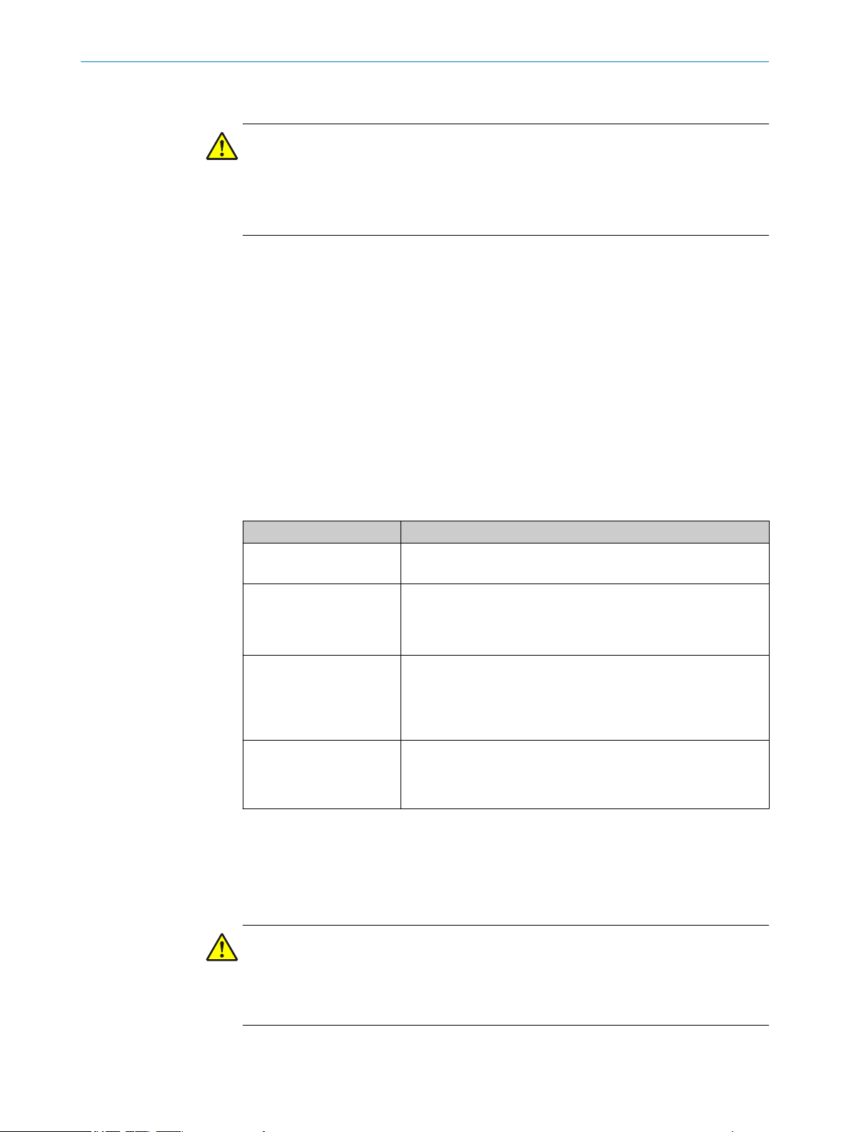
2.5 Requirements for skilled persons and operating personnel
WARNING
Risk of injury due to insufficient training.
Improper handling of the sensor may result in considerable personal injury and material
damage.
■
All work must only ever be carried out by the stipulated persons.
The operating instructions state the following qualification requirements for the various
areas of work:
■
Instructed personnel have been briefed by the operating entity about the tasks
assigned to them and about potential dangers arising from improper action.
■
Skilled personnel have the specialist training, skills, and experience, as well as
knowledge of the relevant regulations, to be able to perform tasks assigned to
them and to detect and avoid any potential dangers independently.
■
Electricians have the specialist training, skills, and experience, as well as knowl‐
edge of the relevant standards and provisions to be able to carry out work on elec‐
trical systems and to detect and avoid any potential dangers independently. In Ger‐
many, electricians must meet the specifications of the BGV A3 Work Safety Regu‐
lations (e.g., Master Electrician). Other relevant regulations applicable in other
countries must be observed.
The following qualifications are required for various activities:
Activities Qualification
Mounting, maintenance
Electrical installation,
device replacement
Commissioning, configura‐
tion
Operation of the devices in
their particular application
Basic practical technical training
■
Knowledge of the current safety regulations in the workplace
■
Practical electrical training
■
Knowledge of current electrical safety regulations
■
Knowledge of the operation and control of the devices in their
■
particular application
Basic knowledge of the design and setup of the described con‐
■
nections and interfaces
Basic knowledge of data transmission
■
Knowledge of the operation and control of the devices in their
■
particular application
Knowledge of the operation and control of the devices in their
■
particular application
Knowledge of the software and hardware environment in the
■
application
2.6 Hazard warnings and operational safety
Please observe the safety notes and the warnings listed here and in other chapters of
these operating instructions to reduce the possibility of risks to health and avoid dan‐
gerous situations.
CAUTION EYE SAFETY
The OLS20 is equipped with LED illumination. The sensor meets the criteria of risk
group 2 according to IEC 62471:2006. The device emits potentially dangerous optical
radiation. Do not look into the lamp for extended periods of time during operation. This
could damage your eyes.
8
O PE R AT I NG IN S TR U CT I ON S | OLS20 8023752/2019-04-01 | SICK
Subject to change without notice
Page 9

2.7 Repairs
SAFETY INFORMATION 2
Repair work on the sensor may only be performed by qualified and authorized person‐
nel from SICK AG. Interruptions or modifications to the sensor on the part of the cus‐
tomer will invalidate any warranty claims against SICK AG.
8023752/2019-04-01 | SICK OP E RA T IN G I N ST R UC T IO N S | OLS20
Subject to change without notice
9
Page 10
1
2
3
4
3 PRODUCT DESCRIPTION
3 Product description
3.1 Product identification
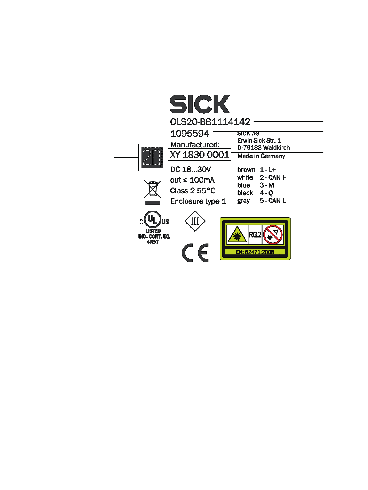
3.1.1 Type label
Figure 1: Type label
Type designation
1
ID no.
2
Serial number
3
Maschine readable code
4
10
O PE R AT I NG IN S TR U CT I ON S | OLS20 8023752/2019-04-01 | SICK
Subject to change without notice
Page 11
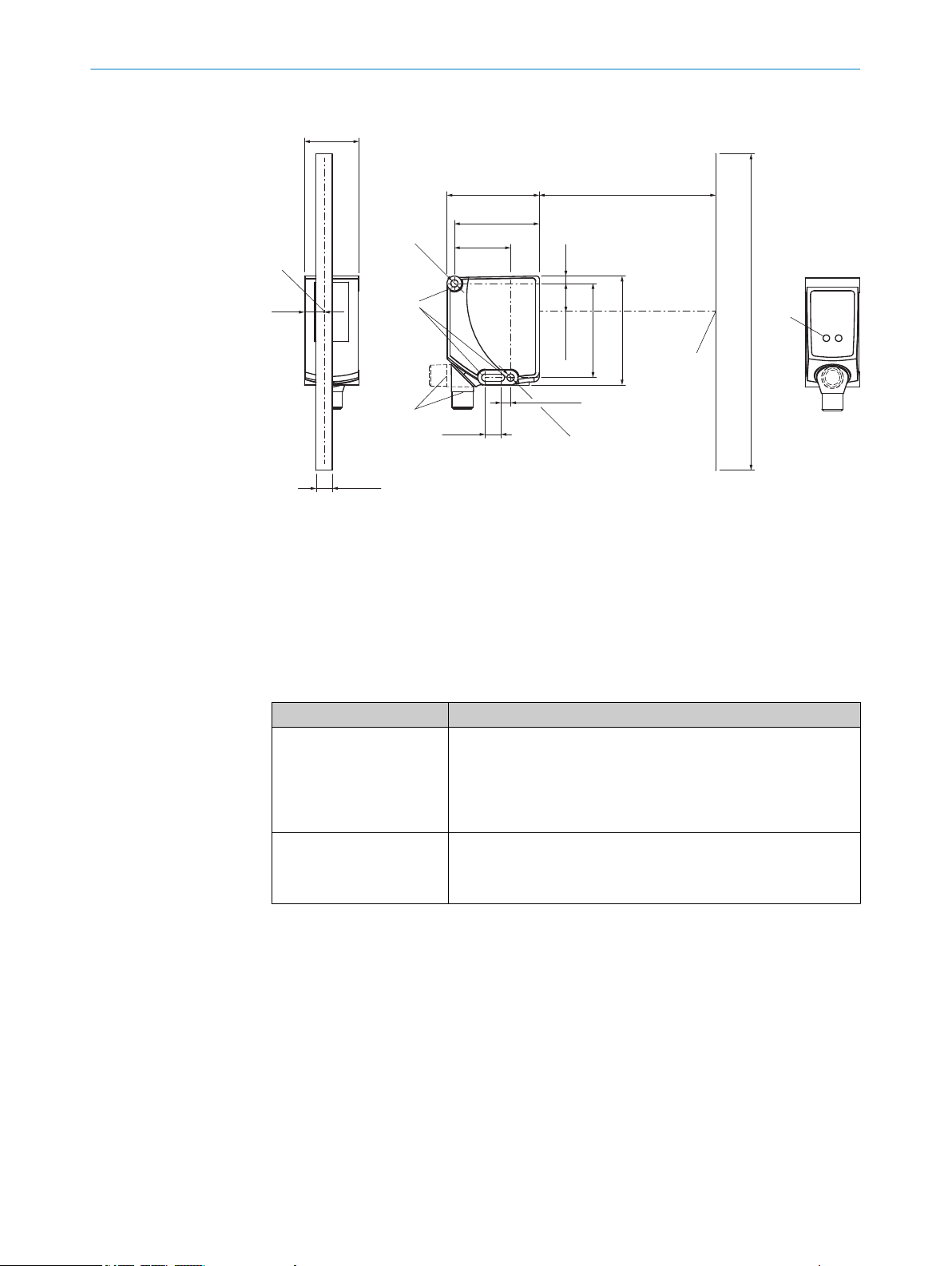
3.1.2 Structure and status indicators
11.3
(0.44)
9.3 (0.37)
5
2
4.2
(0.17)
180 (7.09)
100 (3.94)52.5 (2.07)
48.3 (1.9)
32 (1.26)
Ø
4.1
Ø
4.1
9 (0.35)
5.5 (0.22)
62 (2.44)
53.6 (2.11)
16.3 (0.64)
31 (1.22)
1
4
3
Figure 2: Device view
Optical axis
1
Field of view
2
Fixing hole
3
M12 device connection, can be rotated by 90°
4
Display unit
5
PRODUCT DESCRIPTION 3
Function indicators (LEDs)
Table 1: Function indicators (LEDs)
Function indicator Description
Q Switching output display
Yellow LED: Output active
•
LED off: Output inactive
•
LED flashing (10 Hz): Overcurrent/short-circuit protection has
•
triggered
PWR Operating status display
Green LED: Normal operation/Supply voltage on
•
LED off: No operation
•
3.2 Product features
The OLS20 line guidance sensor is an opto-electronic sensor which detects the line
center point of up to three luminescent tracks. To do so, the sensor stimulates the
guide track(s) with blue light and detects the remitted light using a receiver array.
This track is typically conventional adhesive tape or a colorful luminescence track. It is
not necessary to teach in the sensor.
For additional information on the adhesive tape and bar code labels recommended by
SICK, see the product accessories at www.sick.com/ols20.
In addition, the sensor reads 1D codes in “interleaved 2/5” format attached perpendic‐
ular to the track.
8023752/2019-04-01 | SICK OP E RA T IN G I N ST R UC T IO N S | OLS20
Subject to change without notice
11
Page 12

4 TRANSPORT AND STORAGE
4 Transport and storage
4.1 Transport
Improper transport
CAUTION DAMAGE TO THE PATTERN SENSOR DUE TO IMPROPER TRANSPORT!
Substantial material damage may result in the event of improper transport.
For this reason:
The device should be transported only by trained specialist staff.
•
The utmost care and attention is required at all times during unloading and trans‐
•
portation on company premises.
Note the symbols on the packaging.
•
Do not remove packaging until immediately before starting installation work.
•
4.2 Transport inspection
Immediately upon receipt at the receiving work station, check the delivery for complete‐
ness and for any damage that may have occurred in transit. In the case of transit dam‐
age that is visible externally, proceed as follows:
■
Do not accept the delivery or only do so conditionally.
■
Note the scope of damage on the transport documents or on the transport com‐
pany’s delivery note.
■
File a complaint.
4.3 Storage
NOTE
Complaints regarding defects should be filed as soon as these are detected. Damage
claims are only valid before the applicable complaint deadlines.
Store the device under the following conditions:
■
Recommendation: Use the original packaging.
■
Do not store outdoors.
■
Store in a dry area that is protected from dust.
■
To allow any residual dampness to evaporate, do not package in airtight contain‐
ers.
■
Do not expose to any aggressive substances.
■
Protect from sunlight.
■
Avoid mechanical shocks.
■
Storage temperature: see "Ambient conditions", page 34.
■
Relative humidity: see "Ambient conditions", page 34.
■
For storage periods of longer than 3 months, check the general condition of all
components and packaging on a regular basis.
12
O PE R AT I NG IN S TR U CT I ON S | OLS20 8023752/2019-04-01 | SICK
Subject to change without notice
Page 13

5 Mounting
5.1 Preparation for mounting
1 Select the mounting site for the OLS20 in accordance with the following chapter
"Installation requirements", page 13.
2 Mount the OLS20 using the fixing holes.
"Structure and status indicators", page 11
"Accessories", page 35
5.1.1 Installation requirements
NOTICE
Radio interference may occur when the sensor is used in residential areas.
Only use the device in industrial environments (EN 61000-6-4).
■
Typical space requirements for sensor, see "Structural design", page 34.
■
Comply with technical parameters such as the permitted ambient conditions for
the operation of the sensor (e.g., temperature range, EM interference), see "Ambi‐
ent conditions", page 34.
■
Protect the sensor from direct sunlight.
■
Only affix the sensor using accessories supplied for this purpose -> there are no
screw connections on the sensor.
■
The light spot must cover the possible area of the three tracks.
■
Sensing distance: 100 mm
The sensing distance is the distance from the front sensor edge (housing edge) to
the track or the ground.
MOUNTING 5
5.1.2 Scope of delivery
The following are included with delivery:
OLS20 Optical Line Guidance Sensor
•
1 quick-start guide
•
Accessories:
Accessories (e.g., cables, fastening adapters) are only supplied if ordered separately.
5.2 Mounting the sensor
Arrangement over guide track
The OLS20 must be aligned orthogonally to the guide track with its light spot. The sens‐
ing range is 100 mm.
The sensor should be attached vertically over the guide track.
8023752/2019-04-01 | SICK OP E RA T IN G I N ST R UC T IO N S | OLS20
Subject to change without notice
13
Page 14

MOUNTING
5
Table 2: Mounting
Figure 3: Arrangement over guide track
The code can be arranged directly on the track or next to the track. If it is arranged next
to the track (field of view +/-50 mm), it is detected as an additional track.
14
O PE R AT I NG IN S TR U CT I ON S | OLS20 8023752/2019-04-01 | SICK
Subject to change without notice
Page 15

+90 mm
-90 mm
0 mm
MOUNTING 5
Figure 4: Arrangement with branches and junctions
Arrangement with branches and junctions
If there are branches or junctions, we recommend arranging the tracks as illustrated.
The minimum distance between the tracks is 7 mm.
In addition, we recommend a minimum overlap length of the tracks of at least 10 cm.
At speeds greater than 2 m / s, this range should be increased.
Figure 4 also shows the sign convention of the LCP with the factory settings. (-90 mm ...
+90 mm on the cable side).
8023752/2019-04-01 | SICK OP E RA T IN G I N ST R UC T IO N S | OLS20
Subject to change without notice
15
Page 16

6 ELECTRICAL INSTALLATION
6 Electrical installation
6.1 Safety
6.1.1 Notes on electrical installation
CAUTION
Danger due to incorrect supply voltage!
An incorrect supply voltage may result in injuries from electric shocks and/or damage to
the device.
■
Only operate the sensor with safety/protective extra-low voltage (SELV/PELV).
NOTICE
Sensor damage or unpredictable operation due to working with live parts.
Working with live parts may result in unpredictable operation.
■
Only carry out wiring work when the power is off.
■
Only connect and disconnect electrical connections when the power is off.
■
The electrical installation must only be performed by electrically qualified person‐
nel.
■
Standard safety requirements must be observed when working on electrical sys‐
tems!
■
Only switch on the supply voltage for the device when the connection tasks have
been completed and the wiring has been thoroughly checked.
■
When using extension cables with open ends, ensure that bare wire ends do not
come into contact with each other (risk of short-circuit when supply voltage is
switched on!). Wires must be appropriately insulated from each other.
■
Wire cross-sections in the supply cable from the user’s power system must be
designed in accordance with the applicable standards. When this is being done in
Germany, observe the following standards: DIN VDE 0100 (Part 430) and DIN VDE
0298 (Part 4) and/or DIN VDE 0891 (Part 1).
■
Electrical circuits connected to the device must be configured as SELV circuits
(SELV = safety extra-low voltage/PELV = protective extra-low voltage).
■
Protect the device with a separate fuse at the start of the supply circuit.
6.1.2 Wiring notes
16
O PE R AT I NG IN S TR U CT I ON S | OLS20 8023752/2019-04-01 | SICK
A shielded cable is not required in order to adhere to the electromagnetic compatibility
guidelines specified by DIN EN 60947-5-2. It is recommended, however, especially
when working with longer connecting cables.
The IP enclosure rating for the sensor is only achieved if the connected cable is com‐
pletely screwed in.
CAUTION
This is a class A product. In a household environment, this device can cause radio inter‐
ference. The user should take appropriate measures as required.
NOTE
Preassembled cables can be found online at:
www.sick.com/ols20
b
Subject to change without notice
Page 17

1
2
4
3
1
2
4
3
90
90
1
2
3
4
1
2
3
4
ELECTRICAL INSTALLATION
Please observe the following wiring notes:
■
During installation, pay attention to the different cable groups. The cables are
grouped into the following four groups according to their sensitivity to interference
or radiated emissions:
Group 1: Cables very sensitive to interference, such as analog measuring
°
cables
Group 2: Cables sensitive to interference, such as sensor cables, communi‐
°
cation signals, bus signals
Group 3: Cables which are a source of interference, such as control cables
°
for inductive loads, motor brakes
Group 4: Cables which are powerful sources of interference, such as output
°
cables from frequency inverters, welding system power supplies, power
cables
w
Cables in groups 1, 2 and 3, 4 must be crossed at right angles, see figure 5.
w
Cables in groups 1, 2 and 3, 4 must be routed in different cable channels or
metallic separators must be used, see figure 6 and see figure 7. This applies
particularly where cables of devices with a high level of radiated emission,
such as frequency converters, are laid parallel to sensor cables.
6
Figure 5: Cross cables at right angles
Figure 6: Ideal laying – Place cables in different cable channels
8023752/2019-04-01 | SICK OP E RA T IN G I N ST R UC T IO N S | OLS20
Subject to change without notice
Figure 7: Alternative laying – Separate cables with metallic separators
17
Page 18

1
2
5
4 3
1
2
5
4 3
6 ELECTRICAL INSTALLATION
6.2 Pin assignment of the connections
M12 connection
Pin Pin assignment
1 - BN VIN
2 - WH CAN HIGH
3 - BU GND
4 - BK C / Q
5 - GY CAN LOW
M12 connection, RS485
Pin Pin assignment
1 - BN VIN
2 - WH RS485 A
3 - BU GND
4 - BK C / Q
5 - GY RS485 B
6.3 Connecting the supply voltage
The sensor must be connected to a voltage supply with the following properties:
Supply voltage DC 18 V ... 30 V (stabilized safety extra-low voltage (SELV/PELV) as
•
per current standard EN 60950-1)
Electricity source with at least 3 W power
•
Protecting the supply cables
To ensure protection against short-circuits/overload in the customer’s supply cables,
the wire cross-sections used must be appropriately selected and protected.
The following standards must be observed in Germany:
DIN VDE 0100 (part 430)
•
DIN VDE 0298 (part 4) and/or DIN VDE 0891 (part 1)
•
18
Electrical connection of OLS20
Ensure the voltage supply is not connected.
•
Turn the swivel connector into the desired position.
•
Connect the sensor according to the connection diagram.
•
O PE R AT I NG IN S TR U CT I ON S | OLS20 8023752/2019-04-01 | SICK
Subject to change without notice
Page 19

6.4 CAN connection
We recommend connecting the ground cable to the CANopen communication interface
as a reference.
If there is no separate CAN GND in the system, this pin is to be connected to the FE.
ELECTRICAL INSTALLATION 6
8023752/2019-04-01 | SICK OP E RA T IN G I N ST R UC T IO N S | OLS20
Subject to change without notice
19
Page 20

7 COMMISSIONING
7 Commissioning
7.1 Overview of commissioning steps
■
Connect the voltage supply.
■
Commission the sensor using the factory settings.
■
Configure the sensor.
7.2 Commissioning the sensor for the first time
NOTICE PUSHBUTTON DAMAGE DUE TO IMPROPER HANDLING!
Improper handling of the pushbuttons can damage them. This will make operation diffi‐
cult or impossible.
For this reason:
Only operate the pushbuttons with your fingers or a suitable pointing device.
•
Do not operate the pushbuttons using sharp or hard objects.
•
Establish voltage supply: When the sensor voltage supply is correct, the green “PWR”
LED lights up.
If at least one track is detected, switching output Q1 is “active” and the yellow “Q” LED
lights up.
7.3 First step to commissioning with CANopen
7.3.1 Setting the ID and baud rate
The following conditions must be met for communication with the CAN master:
A correct node ID must be set on the OLS20.
•
Correct is:
A node ID which is free in the CANopen network
°
A node ID which the master expects
°
The same baud rate must be set in the OLS20 as in the master.
•
The following parameters are factory set on the OLS20:
Node ID: 10
•
Baud rate: 125 kbit/s
•
The following communication parameters can be allocated to the OLS20:
Node ID: 1 to 127 (0 is generally assigned to the master)
•
Baud rate: 10 kbit/s, 20 kbit/s, 50 kbit/s, 125 kbit/s, 250 kbit/s, 500 kbit/s,
•
1,000 kbit/s
The sensor supports the configuration with LSS with a CANopen master.
The node ID and baud rate can also be set using the SOPAS ET configuration software,
which can be downloaded at: www.sick.com/SOPAS.
7.3.2 Process data objects (PDOs)
The OLS20 supports two transmit PDOs and no receive PDO.
Objects 0x1800 and 0x1801 contain the communication parameters.
20
O PE R AT I NG IN S TR U CT I ON S | OLS20 8023752/2019-04-01 | SICK
Subject to change without notice
Page 21

7.3.3 PDO communication
The transmission type is factory-set to acyclic communication for TPDO1 and TPDO2. A
transmission period of 20 ms is factory-set for TPDO1 and TPDO2 so that TPDO1 and
TPDO2 are transmitted on a cyclical basis.
Changing the factory-set transmission type
The following options are available for the cyclical or acyclical output of transmit PDOs
by the OLS20:
Change the event timer in object 0x1800 or 0x1801 (see table 3)
•
Change the transmission type in object 0x1800 or 0x1801 (see table 3)
•
7.4 First step to commissioning with Modbus RTU
7.4.1 Setting the ID and baud rate
The following conditions must be met for communication with the Modbus master:
A correct slave address must be set on the OLS20.
•
Correct is:
A slave address that is free in the Modbus network
°
A slave address that the master expects
°
The same baud rate must be set in the OLS20 as in the master.
•
The following parameters are factory set on the OLS20:
COMMISSIONING
7
Slave address: 10 (valid settings 1 ... 247)
•
Baud rate: 9600 bps
•
The following communication parameters can be allocated to the OLS20:
Slave address: 1 to 247 (0 is generally assigned to the master)
•
Baud rate:
•
0: 1200 bps
1: 2400 bps
2: 4800 bps
3: 9600 bps
4: 19200 bps
5: 38400 bps
6: 57600 bps
7: 115200 bps
The slave address and baud rate can also be set using the SOPAS ET configuration soft‐
ware,
which can be downloaded at: www.sick.com/SOPAS.
8023752/2019-04-01 | SICK OP E RA T IN G I N ST R UC T IO N S | OLS20
Subject to change without notice
21
Page 22

8 OPERATION
8 Operation
8.1 Operation via CANopen
CANopen object directory
This chapter contains information on integration of the sensor using CANopen.
All sensor functions can be accessed via the CANopen interface. All settings can be
configured in this interface. The EDS file can also be found at www.sick.com/ols20.
8.1.1 OBD
This section only describes the objects that do not have a fixed definition in the
CANopen standard. Default values are listed only for parameters that can be modified
by the user.
Table 3: OBD
Index Sub-
idx
0x1000 - RO Device type UINT32 No device profile sup‐
0x1001 - RO Error register UINT8
0x1005 - RW COB ID
0x1008 - RO Manufac‐
0x1009 - RO Manufac‐
0x100A - RO Manufac‐
0x100C - R/W Guard time UINT16
0x100D - R/W Life time UINT8
0x1014 - RW COB-ID
0x1015 - RW Inhibit Time
0x1016 RO Heartbeat
1 RW Consumer
2 RW Consumer
0x1017 - R/W Heart beat
0x1018 RO Identity
1 RO Vendor Id UINT32 0x01000056 (SICK
R/W Object name Default
value
0x00000080UINT32
SYNC
turer device
name
turer hard‐
ware rev
turer soft‐
ware rev
0x00000080UINT32
EMCY
0x0000 UINT16
Emergency
0x02 UINT32
Consumer
Entries
0x0 UINT32
Heartbeat
Time 1
0x0 UINT32
Heartbeat
Time 2
time
object
Type Description
ported
STRING Optical Line Guid‐
ance Sensor
STRING Hardware version,
sensor
STRING Firmware version,
sensor
UINT16
UINT8
AG)
22
O PE R AT I NG IN S TR U CT I ON S | OLS20 8023752/2019-04-01 | SICK
Subject to change without notice
Page 23

OPERATION 8
Index Sub-
R/W Object name Default
idx
2 RO Product
code
3 RO Revision
number
4 RO Serial num‐
ber
0x1800 Transmit
PDO commu‐
nication
parameter 0
1 R/W COB ID 0x0000018AUINT32 see chapter 8.1.2
2 R/W Transmis‐
sion type
3 RW Inhibit Time 0x0 UINT16
5 R/W Event timer 0x014 UINT16
0x1801 Transmit
PDO Com‐
munication
Parameter 2
1 R/W COB ID 0x0000018AUINT32 see chapter 8.1.2
Type Description
value
UINT32
UINT32
UINT32
0xFF UINT8 see chapter 8.1.2
2 R/W Transmis‐
sion type
3 RW Inhibit Time 0x0 UINT16
5 R/W Event timer 0x014 UINT16 see chapter 8.1.2
0x1A00 RO Transmit
PDO Map‐
ping Para‐
meter 2
1 RW Mapping
Entry 1
2 RW Mapping
Entry 2
3 RW Mapping
Entry 3
4 RW Mapping
Entry 4
5 RW Mapping
Entry 5
6 RW Mapping
Entry 6
7 RW Mapping
Entry 7
0x1A01 RO Transmit
PDO Map‐
ping Para‐
meter 2
1 RW Mapping
Entry 1
0xFF UINT8 see chapter 8.1.2
0x00 UINT32
0x00000000UINT32
0x00000000UINT32
0x00000000UINT32
0x00000000UINT32
0x00000000UINT32
0x00000000UINT32
0x00000000UINT32
0x00 UINT32
0x00000000UINT32
8023752/2019-04-01 | SICK OP E RA T IN G I N ST R UC T IO N S | OLS20
Subject to change without notice
23
Page 24

8 OPERATION
Index Sub-
R/W Object name Default
idx
2 RW Mapping
Entry 2
3 RW Mapping
Entry 3
4 RW Mapping
Entry 4
5 RW Mapping
Entry 5
6 RW Mapping
Entry 6
7 RW Mapping
Entry 7
0x2001 Mounting
parameters
5 R/W Flipped
upside down
0x2002 Tape para‐
meters
1 R/W Typ. width
[m]
2 R/W Min. width
[m]
3 R/W Max. width
[m]
0x2003 Advanced
settings
1 R/W Off delay
track detec‐
tion
2 RW Off Delay
Code Detec‐
tion
Type Description
value
0x00000000UINT32
0x00000000UINT32
0x00000000UINT32
0x00000000UINT32
0x00000000UINT32
0x00000000UINT32
BOOL 0 => Positive posi‐
tions on cable outlet
side
1 => Negative posi‐
tions on cable outlet
side
FLOAT Typical track width.
The specification of
the typical track
width makes it possi‐
ble to output the cor‐
rect line center point
even at the edge of
the reading window.
5 mm FLOAT Minimum track width.
Smaller tracks are
ignored.
75 mm FLOAT Maximum track
width. Wider tracks
are ignored.
100 ms UINT16 If the track is not
detected (contamina‐
tion), the last
detected line center
point is output for a
defined number of
milliseconds.
100 ms UINT16 If the code is not
detected (contamina‐
tion), the last
detected code value
is output for a
defined number of
milliseconds.
24
O PE R AT I NG IN S TR U CT I ON S | OLS20 8023752/2019-04-01 | SICK
Subject to change without notice
Page 25

OPERATION 8
Index Sub-
idx
3 RW Position
0x2018 RO Device sta‐
R/W Object name Default
value
0.0 ms The position values
smoothing
filter coeffi‐
cient
tus
Type Description
are smoothed over a
defined number of
milliseconds.
UINT16 0 = Device is OK
1= Maintenance
required
2 = Out of Specifica‐
tion
3 = Functional Check
4 = Failure
0x2019 RO Order num‐
UINT32 3 = Functional Check
ber
0x2021 Result data
1 RO LCP1
2 RO LCP2
3 RO LCP3
(LCPs)
1
1
1
1
INT16 see chapter 8.1.2
INT16 see chapter 8.1.2
INT16 see chapter 8.1.2
4 RO Status UINT8 see chapter 8.1.2
5 RO Width LCP1
6 RO Width LCP2
7 RO Width LCP3
1
1
1
INT16 see chapter 8.1.2
INT16 see chapter 8.1.2
INT16 see chapter 8.1.2
8 RO Code UINT8 see chapter 8.1.2
9 RO Extended
UINT32 see chapter 8.1.2
code
10 RO BarCode
Centerpoint
11 RO Quality of
Line
INT16 Centerpoint of the
detected bar code
UINT8 Line quality in % Ref‐
erence is a standard‐
ized minimum optical
contrast.
0x2023 Line level Line intensity value.
Reference is a stan‐
dardized line inten‐
sity.
1 RO Intensity line
UINT8
1
2 RO Intensity line
UINT8
2
3 RO Intensity line
UINT8
3
1
LCP = line center point
8.1.2 PDOs
The OLS20 has two TPDOs (TPDO01 and TPDO02) with fixed mapping and no RPDO.
TPDO1 can be accessed under the index 0x0180 + node ID, TPDO02 under 0x280 +
node ID. In its default state (node ID 0x0A), the index for TPDO1 is 0x018A.
The TPDO1 is structured as follows:
8023752/2019-04-01 | SICK OP E RA T IN G I N ST R UC T IO N S | OLS20
Subject to change without notice
25
Page 26

8 OPERATION
Table 4: CANopen PDO01
Byte1 Byte2 Byte3 Byte4 Byte5 Byte6 Byte7 Byte8
TPDO1 LSB
LCP1
Table 5: Byte 7 status
Bit 0 Bit 1 Bit 2 Bit 3 Bit 4 Bit 5 Bit 6 Bit 7
Status #LCP bit0#LCP Bit1#LCP Bit2x Device
Table 6: TPDO2
Byte 1 Byte 2 Byte 3 Byte 4 Byte 5 Byte 6 Byte 7 Byte 8
TPDO2 LSB
Width
line 1
#LCP UINT3 The numbers are assigned the following meanings:
Device status Bool 0 => Sensor ok
Code flipped Bool 0 => Code was read from the minus to the plus side
Code valid Bool 0 => No code read
MSB
LCP1
MSP
Width
line 1
LSB
LCP2
LSB
Width
line 2
MSB
LCP2
MSP
Width
line 2
0 => No track found
2 => One track found
3 => Two tracks found: Diverter on minus side (fac‐
tory setting)
6 => Two tracks found: Diverter on plus side (fac‐
tory setting)
7 => Three tracks found
1 => Sensor not OK, see 0x2018
of the sensor
1 => Code was read from the plus to the minus side
of the sensor
1 => Valid code has been read
LSB
LCP3
status
LSB
Width
line 3
MSB
LCP3
x Code
MSP
Width
line 3
Status Bar code
flipped
x x
Code
valid
Table 7: Byte 8 bar code
Bar code Code 0 ... 255
8.1.3 Transmission types
The transmission type of the respective TPDO can be set in index 0x1800 or 0x1801.
This index comprises the following subindexes:
Table 8: Subindexes
SubindexName Permissible
1 COB-ID - The COB ID is automatically adjusted to the
2 Transmission type 0xFE, 0xFF The transmission type is set here.
3 not used - Not used
4 Compatibility entry - Not used
5 Event timer 0 ... 65535 The event timer sets the time between two
Bit 0-7
Description
values
note ID and should not be amended by the
user.
transmissions from the TPDO in [ms]. A value
of 0 deactivates the transmission of the
process data. The smallest logical value rec‐
ommended here is 10 ms.
26
O PE R AT I NG IN S TR U CT I ON S | OLS20 8023752/2019-04-01 | SICK
Subject to change without notice
Page 27

8.2 Operation via Modbus RTU
“Input registers” register group (read-only)
The “input registers” can be read using function code 0x04.
Device identification section
The device identification details (all of data type ASCII string) can be found from 0x00
onwards in the address range of the input register.
Table 9: Device Identification
Address Name #Registers Description
0 Vendor name 4 SICK AG
4 Product code 4
8 Firmware version 6
14 Vendor URL 6 www.sick.com
20 Product name 16 Optical Line Guidance Sensor
36 Model name 9 OLS20XXXX
45 Serial number 4
49 Application name 16
65 SickModbusProfileVersion 6
OPERATION 8
Index section
The registers of the index section contain the addresses (data type UINT16) of the sub‐
sequent sections. The registers are therefore all 2 bytes in size and hold the same con‐
tent. The values are stored in the following table:
Table 10: Index
Address Name Value
128 Number of sections within table 0x4
129 Length of section 1 - Status 0x1
130 Start address of section 1 0x00F0
131 Register type of section 1 0x0
132 Length of section 2 - Results 0x0B
133 Start address of section 2 0x00C0
134 Register type of section 2 0x0
135 Length of section 3 - Commands 0x10
136 Start address of section 3 0x0060
137 Register type of section 3 0x1
138 Length of section 4 - Configuration 0x9
139 Start address of section 4 0x0090
140 Register type of section 4 0x1
Result section
The result data start at address 0xC0:
Table 11: Results
Address Contents #Registers
192 Status 1
193 BCP 1
8023752/2019-04-01 | SICK OP E RA T IN G I N ST R UC T IO N S | OLS20
Subject to change without notice
27
Page 28

8 OPERATION
Address Contents #Registers
194 Bar code 2
196 LCP1 1
197 LCP2 1
198 LCP3 1
199 Width1 1
200 Width2 1
201 Width3 1
202 Quality of Line 1
Status section
Table 12: Status
Address Contents #Registers
240 Device status 1
“Holding registers” register group (read-write)
The following registers are used to configure the sensor via Modbus and can be read
using function code 0x03, written to individually using function code 0x06, or written to
continuously using function code 0x10.
Commands section
Table 13: Commands
Address Contents #Registers
96 Set Application name 16
Configuration section
Table 14: Configuration
Address Contents #Registers Description
144 Reading direction 1 0: Head to connector
1: Connector to head
145 Typical tape width 1 Unit [mm]
146 Minimum tape width 1 Unit [mm]
147 Maximum tape width 1 Unit [mm]
148 Q off delay 1 Unit [ms]
149 Barcode off delay 1 Unit [ms]
150 Q inverter 1 0: not inverted
1: inverted
151 Position smoothing filter coeffi‐
cient
2 FLOAT (≥ 0.0)
Default 2.0
8.3 General notes on operation
8.3.1 Output of line center points
The OLS20 is capable of detecting up to three line center points (LCPs). The position of
each line center point is output to a resolution of 1 mm. The geometric center of the
sensor’s longitudinal axis is the zero point, see "optical center", page 11.
28
O PE R AT I NG IN S TR U CT I ON S | OLS20 8023752/2019-04-01 | SICK
Subject to change without notice
Page 29

x m m m
OPERATION 8
By default, the positive measuring range is towards the cable outlet, and the negative
measuring range is on the opposite side.
If only one line center point is found, this is output as LCP2. If a further line center point
is found, it is output as LCP1 or LCP3, depending on its direction. If three LCPs are
found, then each LCP is output.
If there are multiple tracks in the field of view, the track closest to zero is the main track
(LCP2).
To make it easier for the control system to evaluate this data, the combination of tracks
detected is output in an additional data item #LCP. The LCPs are binary-weighted:
Table 15: Line center points
LCP1 detected LCP2 detected LCP3 detected #LCP Note
no no no 0 Special case: No track
detected
no Yes no 2 Only one track detected
Yes Yes no 3 Single diverter on the minus
side detected (factory set‐
ting)
no Yes Yes 6 Single diverter on the plus
side detected (factory set‐
ting)
Yes Yes Yes 7 Double diverter detected
The principle of LCP1 < LCP2 < LCP3 always applies to the LCPs.
8.3.2 Inversion of the relative position
This function enables the user to invert the convention that the positive range is at the
cable outlet. This makes it easier to install the sensor when rotated by 180°.
The position can be inverted via CANopen, or via Modbus or IO-Link.
The inversion of the position signal (sensor flipped) does not affect the LED behavior.
8.3.3 Bar code detection
The OLS20 has the option of detecting 1D bar codes in the interleaved 2/5 format. Up
to 4-digit bar codes are detected and read out in this case.
The OLS20 outputs the number value of the bar code via CANopen, or via Modbus or
IO-Link.
In addition to track tape, SICK also offers a set of numbered bar codes as accessories
see "Accessories", page 35. The assignment of the bar code value to a certain drive
command or piece of position information must be done on the control side.
8023752/2019-04-01 | SICK OP E RA T IN G I N ST R UC T IO N S | OLS20
Subject to change without notice
29
Page 30

9 MAINTENANCE
9 Maintenance
9.1 Cleaning
CAUTION DEVICE DAMAGE DUE TO IMPROPER CLEANING!
Improper cleaning may result in device damage.
For this reason:
•
•
Clean the front screen at regular intervals with a lint-free cloth and plastic cleaning
agent. Cleaning agents containing solvents are not allowed.
The cleaning interval essentially depends on the ambient conditions.
9.2 Maintenance
The sensor requires the following maintenance work at regular intervals:
Table 16: Maintenance schedule
Interval Maintenance work To be performed by
Cleaning interval depends on
ambient conditions and climate
Every 6 months Check the screw connections
Never use cleaning agents containing aggressive substances.
Never use sharp objects for cleaning.
Clean housing, particularly the
front screen.
and plug connectors.
Specialist
Specialist
9.3 Repairs
Repairs on the sensor may only be carried out by the manufacturer. Any interruption or
modification of the sensor will invalidate the manufacturer warranty.
30
O PE R AT I NG IN S TR U CT I ON S | OLS20 8023752/2019-04-01 | SICK
Subject to change without notice
Page 31

10 Decommissioning
10.1 Decommissioning
Removing the sensor
1. Switch off the supply voltage to the sensor.
2. Detach all connecting cables from the sensor.
3. If the sensor is being replaced, mark its position and alignment on the bracket or
surroundings.
4. Remove the sensor from the slot.
Disposing of the sensor
Any sensor which can no longer be used must be disposed of in an environmentally
friendly manner in accordance with the applicable country-specific waste disposal regu‐
lations. The sensor is electronic waste and must under no circumstances be disposed
of with general waste.
DECOMMISSIONING 10
8023752/2019-04-01 | SICK OP E RA T IN G I N ST R UC T IO N S | OLS20
Subject to change without notice
31
Page 32

11 TROUBLESHOOTING
11 Troubleshooting
Potential faults and rectification measures are described in the table below and in the
next chapter.
In the case of faults that cannot be rectified using the information below, please con‐
tact the manufacturer. See the back page for your agency.
11.1 Possible error indicators
Table: Possible error indicators
Error pattern Possible causes Troubleshooting
Q-LED flashes yellow Short-circuit / Overcurrent /
Sensor is not connected prop‐
erly
Disconnect sensor from the
power network / Check pin
assignment / Reconnect sen‐
sor / Check the current at the
switching output
32
O PE R AT I NG IN S TR U CT I ON S | OLS20 8023752/2019-04-01 | SICK
Subject to change without notice
Page 33

12 Technical data
NOTE
The relevant online data sheet for the OLS20, including technical data, dimensions, and
connection diagrams, can be downloaded, saved, and printed at www.sick.com/ols20.
12.1 Optics / Features
Table 17: Optics / Features
Light sender
Wavelength 450 nm
Light spot size 180 mm x 11 mm
Sensing distance 100 mm
Sensing distance tolerance ± 10 mm
Sensing rate 5 ms
Bar code types 2/5 interleaved
Module width (min.) ≥ 1.5 mm
Track radius (min.) ≥ 0.5 m
Initialization time < 10 s
1
Average service life 100,000 h at TU = +25 °C.
TECHNICAL DATA 12
1
Blue LED
Track field of view +/-90 mm
Code field of view +/-50 mm
12.2 Supply
12.3 Interfaces
12.4 Output
Table 18: Supply
Supply voltage V
Power consumption (with‐
1
S
18 V DC … 30 V DC
< 3 W
out load)
Residual ripple < 5 Vss within permitted supply voltage UV (must not exceed or be
less than the UV tolerances.)
1
Limit values
Table 19: Interfaces
CANopen
1
Configuration and process interfaces
IO-Link (V1.1, COM3)
Modbus (RS485)
1
Configuration and process interfaces
IO-Link (V1.1 COM3)
1
depending on type
Table 20: Output
Switching output Q PUSH/PULL
Active ≥ UV – 2 V
•
Inactive ≤ 2 V
•
Circuit protection Output Q1 overcurrent and short-circuit protection (see Table 1)
8023752/2019-04-01 | SICK OP E RA T IN G I N ST R UC T IO N S | OLS20
Subject to change without notice
33
Page 34

12 TECHNICAL DATA
Maximum output current < 100 mA (total I
12.5 Ambient conditions
Table 21: Ambient conditions
Protection class III, for operation with safety/protective extra-low voltage (SELV/
Electromagnetic compati‐
bility
Ambient temperature range –10 °C … +55 °C
Storage temperature range –20 °C … +75 °C
Ambient light immunity 60,000 lx
Enclosure rating IP64
Noise EN60068-2-64
Shock resistance/Impact
load
12.6 Structural design
Table 22: Structural design
Dimensions (W x H x D) 31 mm x 62 mm x 52.5 mm
Weight 250 g
Materials Housing: metal, discharge plate: glass
Connections
1
Male connector IN = 2 A
2
Use of a shielded cable is recommended for longer cables.
= Q1)
OUT
PELV)
EN 61000-6-2, EN 55011, Class A
EN 60086-2-27
Male connector, M121, 5-pin
•
2
34
O PE R AT I NG IN S TR U CT I ON S | OLS20 8023752/2019-04-01 | SICK
Subject to change without notice
Page 35

13 Accessories
NOTE
Accessories can be found on the online product page at:
www.sick.com/ols20
ACCESSORIES 13
8023752/2019-04-01 | SICK OP E RA T IN G I N ST R UC T IO N S | OLS20
Subject to change without notice
35
Page 36

14 LICENSES
14 Licenses
SICK uses open-source software. This software is licensed by the rights holders using
the following licenses among others: the free licenses GNU General Public License (GPL
Version2, GPL Version3) and GNU Lesser General Public License (LGPL), the MIT
license, zLib license, and the licenses derived from the BSD license.
This program is provided for general use, but WITHOUT ANY WARRANTY OF ANY KIND.
This warranty disclaimer also extends to the implicit assurance of marketability or suit‐
ability of the program for a particular purpose.
More details can be found in the GNU General Public License. For complete license
texts, see www.sick.com/licensetexts. Printed copies of the license texts are also avail‐
able on request.
36
O PE R AT I NG IN S TR U CT I ON S | OLS20 8023752/2019-04-01 | SICK
Subject to change without notice
Page 37

15 Annex
15.1 EU declaration of conformity
The EU declaration of conformity can be downloaded from the Internet at:
www.sick.com/ols20
ANNEX 15
8023752/2019-04-01 | SICK OP E RA T IN G I N ST R UC T IO N S | OLS20
Subject to change without notice
37
Page 38

Further locations at www.sick.com
Australia
Phone +61 (3) 9457 0600
1800 33 48 02 – tollfree
E-Mail sales@sick.com.au
Austria
Phone +43 (0) 2236 62288-0
E-Mail office@sick.at
Belgium/Luxembourg
Phone +32 (0) 2 466 55 66
E-Mail info@sick.be
Brazil
Phone +55 11 3215-4900
E-Mail comercial@sick.com.br
Canada
Phone +1 905.771.1444
E-Mail cs.canada@sick.com
Czech Republic
Phone +420 2 57 91 18 50
E-Mail sick@sick.cz
Chile
Phone +56 (2) 2274 7430
E-Mail chile@sick.com
China
Phone +86 20 2882 3600
E-Mail info.china@sick.net.cn
Denmark
Phone +45 45 82 64 00
E-Mail sick@sick.dk
Finland
Phone +358-9-25 15 800
E-Mail sick@sick.fi
France
Phone +33 1 64 62 35 00
E-Mail info@sick.fr
Germany
Phone +49 (0) 2 11 53 01
E-Mail info@sick.de
Hong Kong
Phone +852 2153 6300
E-Mail ghk@sick.com.hk
Hungary
Phone +36 1 371 2680
E-Mail ertekesites@sick.hu
India
Phone +91-22-6119 8900
E-Mail info@sick-india.com
Israel
Phone +972-4-6881000
E-Mail info@sick-sensors.com
Italy
Phone +39 02 27 43 41
E-Mail info@sick.it
Japan
Phone +81 3 5309 2112
E-Mail support@sick.jp
Malaysia
Phone +603-8080 7425
E-Mail enquiry.my@sick.com
Mexico
Phone +52 (472) 748 9451
E-Mail mario.garcia@sick.com
Netherlands
Phone +31 (0) 30 229 25 44
E-Mail info@sick.nl
New Zealand
Phone +64 9 415 0459
0800 222 278 – tollfree
E-Mail sales@sick.co.nz
Norway
Phone +47 67 81 50 00
E-Mail sick@sick.no
Poland
Phone +48 22 539 41 00
E-Mail info@sick.pl
Romania
Phone +40 356-17 11 20
E-Mail office@sick.ro
Russia
Phone +7 495 283 09 90
E-Mail info@sick.ru
Singapore
Phone +65 6744 3732
E-Mail sales.gsg@sick.com
Slovakia
Phone +421 482 901 201
E-Mail mail@sick-sk.sk
Slovenia
Phone +386 591 78849
E-Mail office@sick.si
South Africa
Phone +27 (0)11 472 3733
E-Mail info@sickautomation.co.za
South Korea
Phone +82 2 786 6321
E-Mail info@sickkorea.net
Spain
Phone +34 93 480 31 00
E-Mail info@sick.es
Sweden
Phone +46 10 110 10 00
E-Mail info@sick.se
Switzerland
Phone +41 41 619 29 39
E-Mail contact@sick.ch
Taiwan
Phone +886-2-2375-6288
E-Mail sales@sick.com.tw
Thailand
Phone +66 2 645 0009
E-Mail marcom.th@sick.com
Turkey
Phone +90 (216) 528 50 00
E-Mail info@sick.com.tr
United Arab Emirates
Phone +971 (0) 4 88 65 878
E-Mail info@sick.ae
United Kingdom
Phone +44 (0)17278 31121
E-Mail info@sick.co.uk
USA
Phone +1 800.325.7425
E-Mail info@sick.com
Vietnam
Phone +65 6744 3732
E-Mail sales.gsg@sick.com
8023752/2019-04-01/en
SICK AG | Waldkirch | Germany | www.sick.com
 Loading...