

Page 1
O P E R A T I N G I N S T R U C T I O N S
OLS10
Line guidance sensors
Page 2

Described product
OLS10
Manufacturer
SICK AG
Erwin-Sick-Str. 1
79183 Waldkirch
Germany
Legal information
This work is protected by copyright. Any rights derived from the copyright shall be
reserved for SICK AG. Reproduction of this document or parts of this document is only
permissible within the limits of the legal determination of Copyright Law. Any modifica‐
tion, abridgment or translation of this document is prohibited without the express writ‐
ten permission of SICK AG.
The trademarks stated in this document are the property of their respective owner.
© SICK AG. All rights reserved.
Original document
This document is an original document of SICK AG.
2
O PE R AT I NG IN S TR U CT I ON S | OLS10 8022017.10HG/2018-07-18 | SICK
Subject to change without notice
Page 3

Contents
1 About this document........................................................................ 5
1.1 Information on the operating instructions.............................................. 5
1.2 Scope......................................................................................................... 5
1.3 Explanation of symbols............................................................................ 5
1.4 Further information................................................................................... 6
1.5 Customer service...................................................................................... 6
2 Safety information............................................................................ 7
2.1 Intended use............................................................................................. 7
2.2 Improper use............................................................................................. 7
2.3 Notes on UL approval............................................................................... 7
2.4 Limitation of liability................................................................................. 7
2.5 Requirements for skilled persons and operating personnel.................. 8
2.6 Hazard warnings and operational safety................................................. 8
2.7 Repairs...................................................................................................... 9
3 Product description........................................................................... 10
3.1 Product identification............................................................................... 10
3.2 Product features....................................................................................... 12
4 Transport and storage....................................................................... 13
4.1 Transport................................................................................................... 13
4.2 Transport inspection................................................................................. 13
4.3 Storage...................................................................................................... 13
5 Mounting............................................................................................. 14
5.1 Preparation for mounting......................................................................... 14
5.2 Mounting the sensor................................................................................ 14
6 Electrical installation........................................................................ 17
6.1 Safety......................................................................................................... 17
6.2 Pin assignment of the connections......................................................... 19
6.3 Connecting the supply voltage................................................................. 20
6.4 CAN connection........................................................................................ 20
7 Commissioning.................................................................................. 21
7.1 Overview of commissioning steps........................................................... 21
7.2 Commissioning the sensor for the first time.......................................... 21
7.3 First step to commissioning with CANopen............................................ 21
8 Operation............................................................................................ 23
8.1 Operating the sensor................................................................................ 23
8.2 Operation via TCP/IP................................................................................ 25
8.3 Operation via CANopen............................................................................ 27
8.4 General notes on operation..................................................................... 31
CONTENTS
8022017.10HG/2018-07-18 | SICK OP E RA T IN G I N ST R UC T IO N S | OLS10
3
Subject to change without notice
Page 4

9 Maintenance...................................................................................... 33
9.1 Cleaning..................................................................................................... 33
9.2 Maintenance............................................................................................. 33
9.3 Repairs...................................................................................................... 33
10 Decommissioning............................................................................. 34
10.1 Decommissioning..................................................................................... 34
11 Troubleshooting................................................................................. 35
11.1 Possible error indicators.......................................................................... 35
11.2 Faults caused by the network connection.............................................. 35
12 Technical data.................................................................................... 37
12.1 Optics / Features...................................................................................... 37
12.2 Supply........................................................................................................ 37
12.3 Interfaces.................................................................................................. 37
12.4 Outputs...................................................................................................... 37
12.5 Ambient conditions................................................................................... 38
12.6 Structural design...................................................................................... 38
13 Accessories........................................................................................ 39
13.1 Connectivity............................................................................................... 39
13.2 Mounting systems..................................................................................... 40
14 Licenses.............................................................................................. 43
14.1 lwIP............................................................................................................ 43
14.2 tinf.............................................................................................................. 43
14.3 jQuery........................................................................................................ 44
14.4 Flot............................................................................................................. 44
15 Menu structure................................................................................... 45
16 Annex.................................................................................................. 46
16.1 EU declaration of conformity.................................................................... 46
CONTENTS
4
O PE R AT I NG IN S TR U CT I ON S | OLS10 8022017.10HG/2018-07-18 | SICK
Subject to change without notice
Page 5

1 About this document
1.1 Information on the operating instructions
These operating instructions provide important information on how to use sensors from
SICK AG.
Prerequisites for safe work are:
•
Compliance with all safety notes and handling instructions supplied.
•
Compliance with local work safety regulations and general safety regulations for
sensor applications.
The operating instructions are intended to be used by qualified personnel and electrical
specialists.
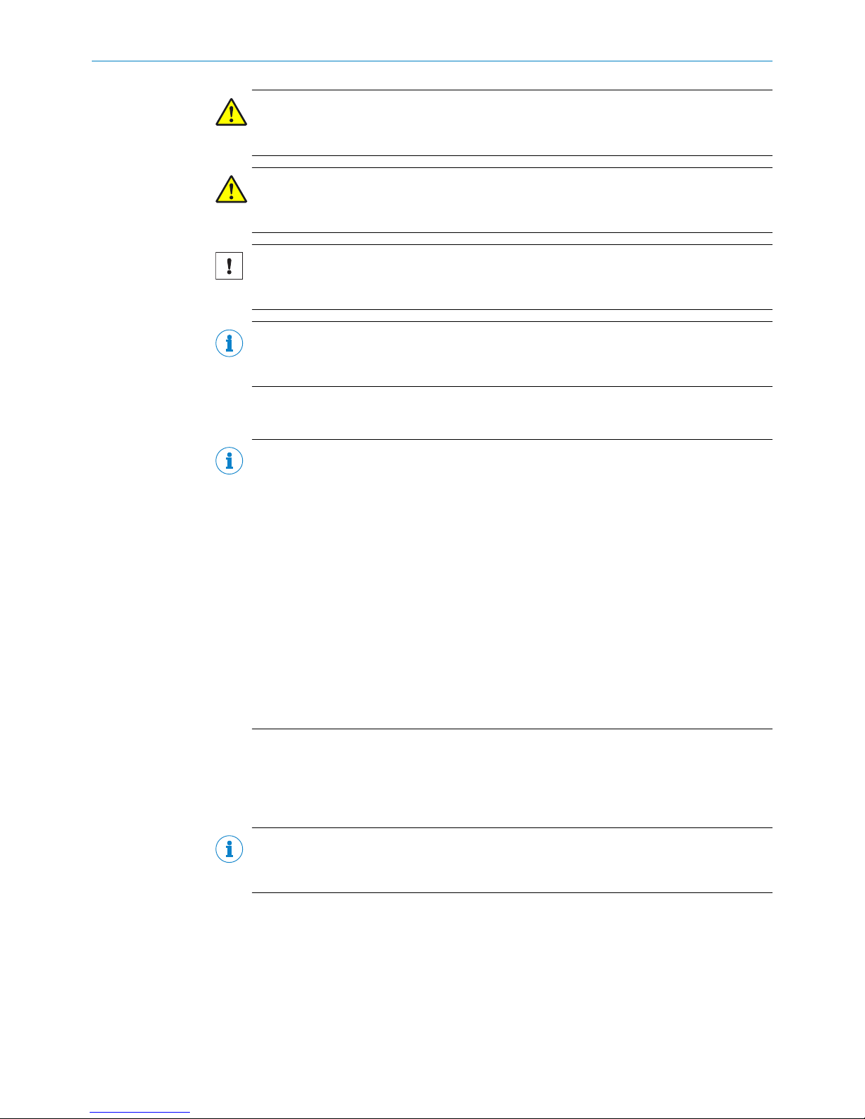
NOTE
Read these operating instructions carefully before starting any work on the sensor, in
order to familiarize yourself with the sensor and its functions.
The instructions constitute an integral part of the product and are to be stored in the
immediate vicinity of the sensor so they remain accessible to staff at all times. If the
sensor is passed on to a third party, these operating instructions should be handed
over with it.
These operating instructions do not provide information on operating the machine in
which the sensor is integrated. For information about this, refer to the operating instruc‐
tions of the particular machine.
1.2 Scope
These operating instructions explain how to incorporate a sensor into a customer sys‐
tem. Instructions are given in stages for all actions required.
These instructions apply to all available device variants of the sensor.
Available device variants are listed on the online product page.
b
www.sick.com/ols10
Commissioning is described using one particular device variant as an example.
Simplified device designation in the document
In the following, the sensor is referred to in simplified form as “OLS10”.
1.3 Explanation of symbols
Warnings and important information in this document are labeled with symbols. The
warnings are introduced by signal words that indicate the extent of the danger. These
warnings must be observed at all times and care must be taken to avoid accidents, per‐
sonal injury, and material damage.
DANGER
… indicates a situation of imminent danger, which will lead to a fatality or serious
injuries if not prevented.
ABOUT THIS DOCUMENT 1
8022017.10HG/2018-07-18 | SICK OP E RA T IN G I N ST R UC T IO N S | OLS10
5
Subject to change without notice
Page 6
WARNING
… indicates a potentially dangerous situation, which may lead to a fatality or serious
injuries if not prevented.
CAUTION
… indicates a potentially dangerous situation, which may lead to minor/slight injuries if
not prevented.
NOTICE
… indicates a potentially harmful situation, which may lead to material damage if not
prevented.
NOTE
… highlights useful tips and recommendations as well as information for efficient and
trouble-free operation.
1.4 Further information
NOTE
All the documentation available for the sensor can be found on the online product page
at:
b
www.sick.com/ols10
The following information is available for download from this page:
•
Type-specific online data sheets for device variants, containing technical data and
dimensional drawings
•
EU declaration of conformity for the product family
•
Dimensional drawings and 3D CAD dimension models in various electronic for‐
mats
•
These operating instructions, available in English and German, and in other lan‐
guages if necessary
•
Other publications related to the sensors described here
•
Publications dealing with accessories
•
EDS device description file
1.5 Customer service
If you require any technical information, our customer service department will be happy
to help. To find your representative, see the final page of this document.
NOTE
Before calling, make a note of all type label data such as type code etc. to ensure faster
processing.
1 ABOUT THIS DOCUMENT
6
O PE R AT I NG IN S TR U CT I ON S | OLS10 8022017.10HG/2018-07-18 | SICK
Subject to change without notice
Page 7

2 Safety information
2.1 Intended use
The OLS10 line guidance sensor is an opto-electronic sensor intended for detecting
luminescent guide tracks as well as reading out 1D codes when they are driven over by
automated guided vehicles.
SICK AG assumes no liability for losses or damage arising from the use of the product,
either directly or indirectly. This applies in particular to use of the product that does not
conform to its intended purpose and is not described in this documentation.
NOTICE
Radio interference may occur when the sensor is used in residential areas.
b
Only use the device in industrial environments (EN 61000-6-4).
2.2 Improper use
•
The sensor does not constitute a safety-relevant device according to the EC
Machinery Directive (2006/42/EC).
•
The sensor must not be used in explosion-hazardous areas.
•
Any other use that is not described as intended use is prohibited.
•
Any use of accessories not specifically approved by SICK AG is at your own risk.
NOTICE
Danger due to improper use!
Any improper use can result in dangerous situations.
Therefore, take note of the following information:
b
The sensor should be used only in line with intended use specifications.
b
All information in these operating instructions must be strictly complied with.
2.3 Notes on UL approval
The device must be supplied by a Class 2 source of supply.
UL Environmental Rating: Enclosure type 1
2.4 Limitation of liability
Applicable standards and regulations, the latest state of technological development,
and our many years of knowledge and experience have all been taken into account
when assembling the data and information contained in these operating instructions.
The manufacturer accepts no liability for damage caused by:
■
Failing to observe the operating instructions
■
Improper use
■
Use by untrained personnel
■
Unauthorized conversions
■
Technical modifications
■
Use of unauthorized spare parts, consumables, and accessories
With special variants, where optional extras have been ordered, or owing to the latest
technical changes, the actual scope of delivery may vary from the features and illustra‐
tions shown here.
SAFETY INFORMATION 2
8022017.10HG/2018-07-18 | SICK OP E RA T IN G I N ST R UC T IO N S | OLS10
7
Subject to change without notice
Page 8
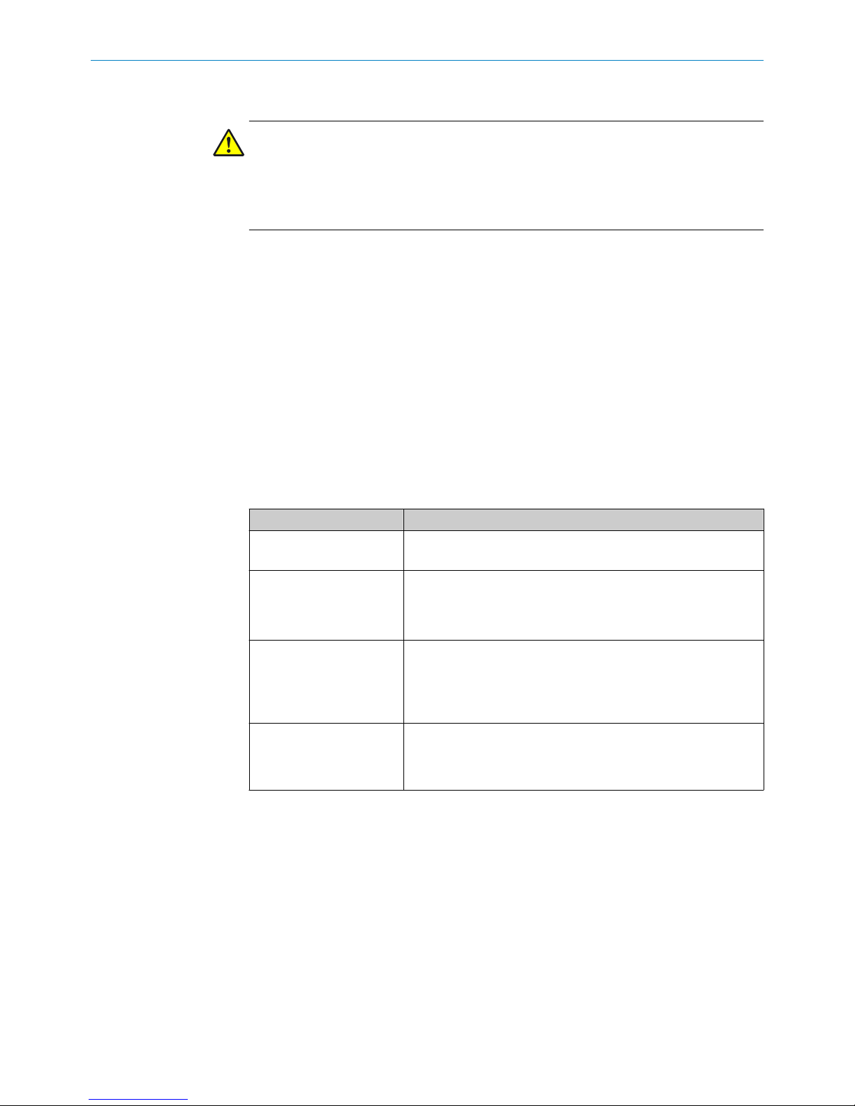
2.5 Requirements for skilled persons and operating personnel
WARNING
Risk of injury due to insufficient training.
Improper handling of the sensor may result in considerable personal injury and material
damage.
■
All work must only ever be carried out by the stipulated persons.
The operating instructions state the following qualification requirements for the various
areas of work:
■
Instructed personnel have been briefed by the operating entity about the tasks
assigned to them and about potential dangers arising from improper action.
■
Skilled personnel have the specialist training, skills, and experience, as well as
knowledge of the relevant regulations, to be able to perform tasks assigned to
them and to detect and avoid any potential dangers independently.
■
Electricians have the specialist training, skills, and experience, as well as knowl‐
edge of the relevant standards and provisions to be able to carry out work on elec‐
trical systems and to detect and avoid any potential dangers independently. In Ger‐
many, electricians must meet the specifications of the BGV A3 Work Safety Regu‐
lations (e.g., Master Electrician). Other relevant regulations applicable in other
countries must be observed.
The following qualifications are required for various activities:
Activities Qualification
Mounting, maintenance
■
Basic practical technical training
■
Knowledge of the current safety regulations in the workplace
Electrical installation,
device replacement
■
Practical electrical training
■
Knowledge of current electrical safety regulations
■
Knowledge of the operation and control of the devices in
their particular application
Commissioning, configura‐
tion
■
Basic knowledge of the design and setup of the described
connections and interfaces
■
Basic knowledge of data transmission
■
Knowledge of the operation and control of the devices in
their particular application
Operation of the devices in
their particular application
■
Knowledge of the operation and control of the devices in
their particular application
■
Knowledge of the software and hardware environment in the
application
2.6 Hazard warnings and operational safety
Please observe the safety notes and the warnings listed here and in other chapters of
these operating instructions to reduce the possibility of risks to health and avoid dan‐
gerous situations.
The OLS10 is equipped with LED illumination. The sensor meets the criteria of risk
group 1 according to IEC 62471:2006. No special measures are required (e.g., eye pro‐
tection).
2 SAFETY INFORMATION
8
O PE R AT I NG IN S TR U CT I ON S | OLS10 8022017.10HG/2018-07-18 | SICK
Subject to change without notice
Page 9

2.7 Repairs
Repair work on the sensor may only be performed by qualified and authorized person‐
nel from SICK AG. Interruptions or modifications to the sensor on the part of the cus‐
tomer will invalidate any warranty claims against SICK AG.
SAFETY INFORMATION 2
8022017.10HG/2018-07-18 | SICK OP E RA T IN G I N ST R UC T IO N S | OLS10
9
Subject to change without notice
Page 10
3 Product description
3.1 Product identification
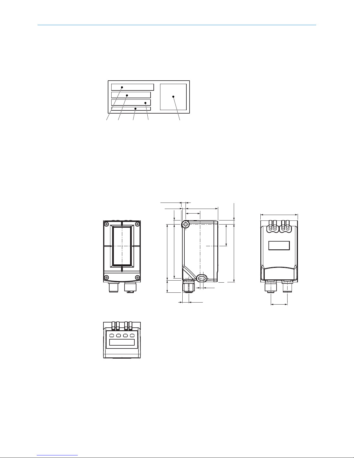
3.1.1 Type label
1
2
3 5
4
Figure 1: Type label
1
Type designation
2
ID no.
3
MAC address
4
Serial number
5
Machine readable code
3.1.2 Operating and status indicators
1
1
2
2
4
5678
20.6
(0.81)
46 (1.81)
18
(0.71)
4
(0.16)
40.2 (1.58)
4 (0.16)
5.2 (0.20)
67 (2.64)
5
(0.20)
27 (1.06)
71.6 (2.82)
7.8
(0.31)
15.3
(0.60)
69.3 (2.73)
4 (0.16)
3
Figure 2: Device view
1
Center of the optical axis
2
Fixing hole
3
M12 male connector, 12-pin/M12 female connector, 4-pin, rotatable
4
Display and control unit
5
Function indicator (green) “ON”
6
Function indicator (yellow) “Q”
7
Function indicator (green) “Link”
3 PRODUCT DESCRIPTION
10
O PE R AT I NG IN S TR U CT I ON S | OLS10 8022017.10HG/2018-07-18 | SICK
Subject to change without notice
Page 11
8
Function indicator (yellow) “Act”
Function indicators (LEDs)
Table 1: Function indicators (LEDs)
Function indicator Description
Act Data transfer display
•
Yellow LED: Data transfer
•
LED off: No data transfer
Link Ethernet connection display
•
Green LED: Ethernet connection available
•
LED off: No Ethernet connection available
Q Switching output display
•
Yellow LED: Output high
•
LED off: Output low
•
LED flashing (10 Hz): Overcurrent/short-circuit protection
has triggered
ON Operating status display
•
Green LED: Normal operation/Supply voltage on
•
LED off: No operation
Symbols on the control panel
The following three symbols may appear on the control panel: RUN, MEN and SET.
Table 2: Symbols on the control panel
Symbol Description
RUN RUN lights up: Sensor is in RUN operational status. The value of
the detected code is displayed.
MEN MEN lights up: The current position in the menu structure is dis‐
played.
SET SET lights up: Lowest menu level has been reached. Sensor set‐
tings and values can be changed here.
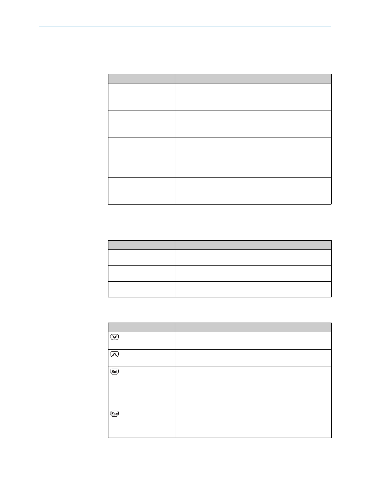
Pushbuttons
Table 3: Pushbuttons
Pushbutton Description
•
Select operating menu, parameter, or option.
•
Reduce value.
•
Select operating menu, parameter, or option.
•
Increase value.
•
Short press:
- switch to the next-lowest menu level
- save parameter change
- confirm selection
•
Long press (> 2 sec.):
- entry to the operating menu.
•
Short press: Exit parameters without saving. Switch to the
next-highest menu level.
•
Long press: Exit parameters without saving. Switch to the
default display.
PRODUCT DESCRIPTION 3
8022017.10HG/2018-07-18 | SICK OP E RA T IN G I N ST R UC T IO N S | OLS10
11
Subject to change without notice
Page 12

3.2 Product features
The OLS10 line guidance sensor is an opto-electronic sensor which detects the line
center point of up to three luminescent tracks. To do so, the sensor stimulates the
guide track(s) with blue light and detects the remitted light using a receiver array.
This track is typically conventional adhesive tape or a colorful luminescence track. It is
not necessary to teach in the sensor.
For additional information on the adhesive tape and bar code labels recommended by
SICK, see (accessories link).
In addition, the sensor reads 1D codes in “interleaved 2/5” format attached perpendic‐
ular to the track.
3 PRODUCT DESCRIPTION
12
O PE R AT I NG IN S TR U CT I ON S | OLS10 8022017.10HG/2018-07-18 | SICK
Subject to change without notice
Page 13

4 Transport and storage
4.1 Transport
Improper transport
CAUTION DAMAGE TO THE PATTERN SENSOR DUE TO IMPROPER TRANSPORT!
Substantial material damage may result in the event of improper transport.
For this reason:
•
The device should be transported only by trained specialist staff.
•
The utmost care and attention is required at all times during unloading and trans‐
portation on company premises.
•
Note the symbols on the packaging.
•
Do not remove packaging until immediately before starting installation work.
4.2 Transport inspection
Immediately upon receipt at the receiving work station, check the delivery for complete‐
ness and for any damage that may have occurred in transit. In the case of transit dam‐
age that is visible externally, proceed as follows:
■
Do not accept the delivery or only do so conditionally.
■
Note the scope of damage on the transport documents or on the transport com‐
pany’s delivery note.
■
File a complaint.
NOTE
Complaints regarding defects should be filed as soon as these are detected. Damage
claims are only valid before the applicable complaint deadlines.
4.3 Storage
Store the device under the following conditions:
■
Recommendation: Use the original packaging.
■
Do not store outdoors.
■
Store in a dry area that is protected from dust.
■
To allow any residual dampness to evaporate, do not package in airtight contain‐
ers.
■
Do not expose to any aggressive substances.
■
Protect from sunlight.
■
Avoid mechanical shocks.
■
Storage temperature: see "Ambient conditions", page 38.
■
Relative humidity: see "Ambient conditions", page 38.
■
For storage periods of longer than 3 months, check the general condition of all
components and packaging on a regular basis.
TRANSPORT AND STORAGE 4
8022017.10HG/2018-07-18 | SICK OP E RA T IN G I N ST R UC T IO N S | OLS10
13
Subject to change without notice
Page 14

5 Mounting
5.1 Preparation for mounting
1 Select the mounting site for the OLS10 in accordance with the following chapter
"Mounting requirements", page 14.
2 Mount the OLS10 using the fixing holes.
"Operating and status indicators", page 10
"Mounting systems", page 40
5.1.1 Mounting requirements
NOTICE
Radio interference may occur when the sensor is used in residential areas.
Only use the device in industrial environments (EN 61000-6-4).
■
Typical space requirements for sensor, see "Structural design", page 38.
■
Comply with technical parameters such as the permitted ambient conditions for
the operation of the sensor (e.g., temperature range, EM interference), see "Ambi‐
ent conditions", page 38.
■
Protect the sensor from direct sunlight.
■
Only affix the sensor using accessories supplied for this purpose -> there are no
screw connections on the sensor.
■
The light spot must cover the possible area of the three tracks. The center of the
light spot is marked with a notch on the upper side of the housing.
■
Sensing distance: 100 mm
The sensing distance is the distance from the front sensor edge (housing edge) to
the track or the ground.
5.1.2 Scope of delivery
The following are included with delivery:
•
OLS10 Optical Line Guidance Sensor
•
Blind plug for M12 Ethernet connection
•
1 quick-start guide
Accessories:
Accessories (e.g., cables, fastening adapters) are only supplied if ordered separately.
5.2
Mounting the sensor
Arrangement over guide track
The OLS10 must be aligned orthogonally to the guide track with its light spot. The sens‐
ing range is 100 mm.
The sensor should be attached vertically over the guide track.
5 MOUNTING
14
O PE R AT I NG IN S TR U CT I ON S | OLS10 8022017.10HG/2018-07-18 | SICK
Subject to change without notice
Page 15
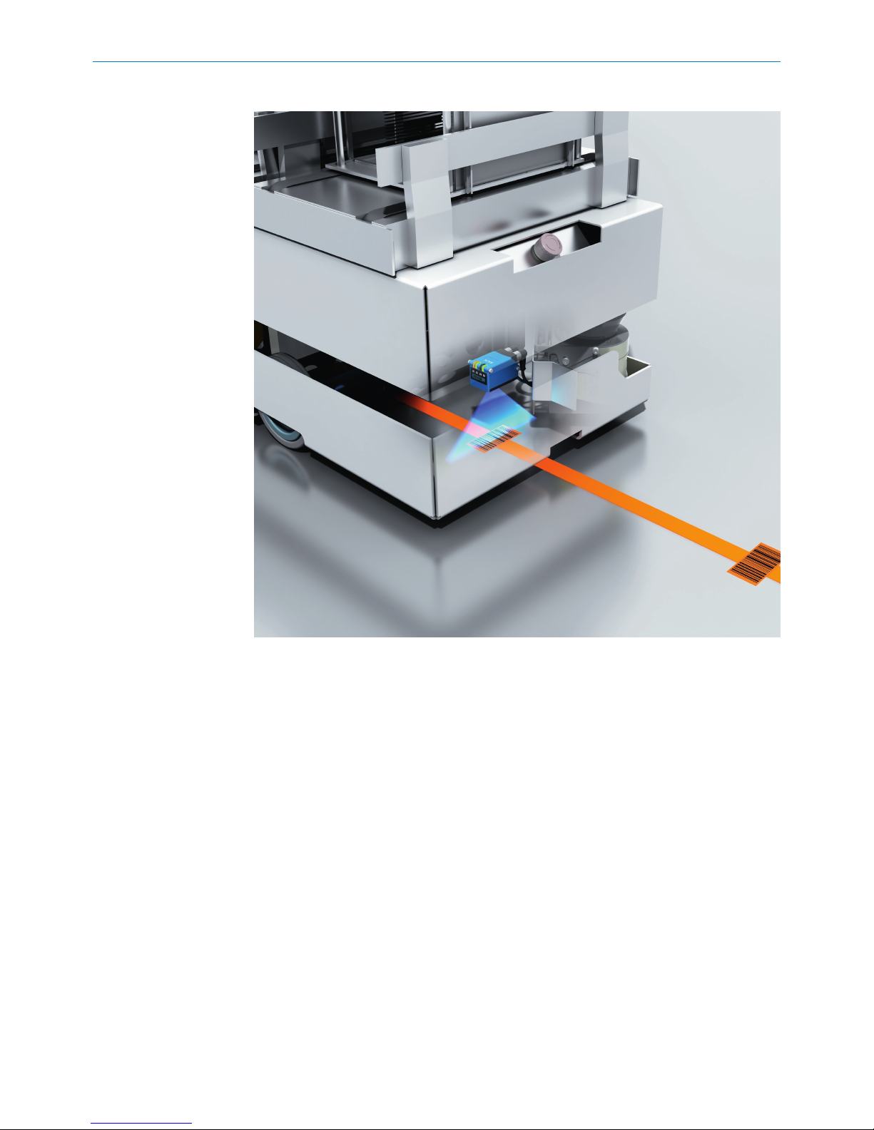
Table 4: Mounting
Figure 3: Arrangement over guide track
The code can be arranged directly on the track or next to the track. If it is arranged next
to the track (field of view +/-50 mm), it is detected as an additional track.
MOUNTING
5
8022017.10HG/2018-07-18 | SICK OP E RA T IN G I N ST R UC T IO N S | OLS10
15
Subject to change without notice
Page 16

Figure 4: Arrangement with branches and junctions
Arrangement with branches and junctions
If there are branches or junctions, we recommend arranging the tracks as illustrated.
The minimum distance between the tracks is 7 mm.
In addition, we recommend a minimum overlap length of the tracks of at least 10 cm.
At speeds higher than 2 m/s as well as when commissioning via Ethernet, this area
must be increased.
Figure 4 also shows the sign convention of the LCP with the factory settings. (-90 mm ...
+90 mm on the cable side).
5 MOUNTING
16
O PE R AT I NG IN S TR U CT I ON S | OLS10 8022017.10HG/2018-07-18 | SICK
Subject to change without notice
Page 17

6 Electrical installation
6.1 Safety
6.1.1 Notes on electrical installation
CAUTION
Danger due to incorrect supply voltage!
An incorrect supply voltage may result in injuries from electric shocks and/or damage to
the device.
■
Only operate the sensor with safety/protective extra-low voltage (SELV/PELV).
NOTICE
Sensor damage or unpredictable operation due to working with live parts.
Working with live parts may result in unpredictable operation.
■
Only carry out wiring work when the power is off.
■
Only connect and disconnect electrical connections when the power is off.
■
The electrical installation must only be performed by electrically qualified person‐
nel.
■
Standard safety requirements must be observed when working on electrical sys‐
tems.
■
Only switch on the supply voltage for the device when the connection tasks have
been completed and the wiring has been thoroughly checked.
■
When using extension cables with open ends, ensure that bare wire ends do not
come into contact with each other (risk of short-circuit when supply voltage is
switched on!). Wires must be appropriately insulated from each other.
■
Wire cross-sections in the supply cable from the user’s power system must be
designed in accordance with the applicable standards. When this is being done in
Germany, observe the following standards: DIN VDE 0100 (Part 430) and DIN VDE
0298 (Part 4) and/or DIN VDE 0891 (Part 1).
■
Electrical circuits connected to the device must be configured as SELV circuits
(SELV = safety extra-low voltage/PELV = protective extra-low voltage).
■
Protect the device with a separate fuse at the start of the supply circuit.
A shielded cable is not required in order to adhere to the electromagnetic compatibility
guidelines specified by DIN EN 60947-5-2. It is recommended, however, especially
when working with longer connecting cables.
The IP enclosure rating for the sensor is only achieved if the connected cable is com‐
pletely screwed in.
6.1.2 Wiring notes
NOTE
Preassembled cables can be found online at:
b
www.sick.com/ols10
Please observe the following wiring notes:
■
During installation, pay attention to the different cable groups. The cables are
grouped into the following four groups according to their sensitivity to interference
or radiated emissions:
ELECTRICAL INSTALLATION 6
8022017.10HG/2018-07-18 | SICK OP E RA T IN G I N ST R UC T IO N S | OLS10
17
Subject to change without notice
Page 18

°
Group 1: Cables very sensitive to interference, such as analog measuring
cables
°
Group 2: Cables sensitive to interference, such as sensor cables, communi‐
cation signals, bus signals
°
Group 3: Cables which are a source of interference, such as control cables
for inductive loads, motor brakes
°
Group 4: Cables which are powerful sources of interference, such as output
cables from frequency inverters, welding system power supplies, power
cables
w
Cables in groups 1, 2 and 3, 4 must be crossed at right angles, see figure 5.
w
Cables in groups 1, 2 and 3, 4 must be routed in different cable channels or
metallic separators must be used, see figure 6 and see figure 7. This applies
particularly where cables of devices with a high level of radiated emission,
such as frequency converters, are laid parallel to sensor cables.
1
2
4
3
1
2
4
3
90
90
Figure 5: Cross cables at right angles
1
2
3
4
Figure 6: Ideal laying – Place cables in different cable channels
1
2
3
4
Figure 7: Alternative laying – Separate cables with metallic separators
NOTE
Prevent equipotential bonding currents via the cable shield with a suitable grounding
method, see "Safety", page 17.
6 ELECTRICAL INSTALLATION
18
O PE R AT I NG IN S TR U CT I ON S | OLS10 8022017.10HG/2018-07-18 | SICK
Subject to change without notice
Page 19

6.2 Pin assignment of the connections
M12 connection
2
3
11
4
5
6
7
8
9
1
10
12
+ (L+)
M
not connected
1
2
BN
BU
3
WH
5
PK
CAN HIGH IN
4
GN
CAN LOW IN
6
YE
CAN GND
7
BK
not connected
9
RD
Q1
10
VT
CAN LOW OUT
11
GY/PK
CAN HIGH OUT
12
RD/BU
not connected
8
GY
Q2
M12 (A-coded)
1
2
FE (shield)
Pin Assignment
1 - BN VIN
2 - BU GND
3 - WH Q2 - valid bar code read
4 - GN CAN HIGH IN
5 - PK N.C.
1
6 - YE CAN LOW IN
7 - BK CAN GND
8 - GY N.C.
1
9 - RD N.C.
1
10 - VT Q1 - track detected
11 - GY/PK CAN LOW OUT
12 - RD/BU CAN HIGH OUT
1
Unconnected pins are to be connected to the GND.
Ethernet connection diagram
The OLS10 features a 100 base-T Ethernet connection.
ELECTRICAL INSTALLATION 6
8022017.10HG/2018-07-18 | SICK OP E RA T IN G I N ST R UC T IO N S | OLS10
19
Subject to change without notice
Page 20

Table 5: Ethernet connection diagram, M12 female connector, 4-pin, D-coded
Tx+
Rx+
Tx–
Rx–
1
2
4
wht/grn
ora
wht/ora
grn
3
M12 (D-coded)
1
4
2
3
Table 6: Ethernet female connector description
Pin Marking Wire color Description
1 Tx+ White/Orange Send data signal, not inverted
2 Rx+ White/Green Receive data signal, not inverted
3 Tx- Orange Send data signal, inverted
4 Rx- Green Receive data signal, inverted
6.3 Connecting the supply voltage
The sensor must be connected to a voltage supply with the following properties:
•
Supply voltage DC 12 V ... 30 V (stabilized safety extra-low voltage (SELV/PELV) as
per current standard EN 60950-1)
•
Electricity source with at least 5 W power
Protecting the supply cables
To ensure protection against short-circuits/overload in the customer’s supply cables,
the wire cross-sections used must be appropriately selected and protected.
The following standards must be observed in Germany:
•
DIN VDE 0100 (part 430)
•
DIN VDE 0298 (part 4) and/or DIN VDE 0891 (part 1)
Electrical connection of OLS10
•
Ensure the voltage supply is not connected.
•
If necessary, turn the swivel connector into the desired position as shown in the
figure.
1
2
•
Connect the sensor according to the connection diagram.
6.4 CAN connection
We recommend connecting the ground cable to the CANopen communication interface
as a reference.
If there is no separate CAN GND in the system, this pin is to be connected to the FE.
6 ELECTRICAL INSTALLATION
20
O PE R AT I NG IN S TR U CT I ON S | OLS10 8022017.10HG/2018-07-18 | SICK
Subject to change without notice
Page 21

7 Commissioning
7.1 Overview of commissioning steps
■
Connect the voltage supply.
■
Commission the sensor using the factory settings.
■
Configure the sensor.
7.2 Commissioning the sensor for the first time
NOTICE PUSHBUTTON DAMAGE DUE TO IMPROPER HANDLING!
Improper handling of the pushbuttons can damage them. This will make operation diffi‐
cult or impossible.
For this reason:
•
Only operate the pushbuttons with your fingers or a suitable pointing device.
•
Do not operate the pushbuttons using sharp or hard objects.
Establish voltage supply: When the sensor voltage supply is correct, the green “ON”
LED lights up.
If at least one track is detected, switching output Q1 is “high” and the yellow “Q” LED
lights up.
If an Ethernet connection is established, the green “Link” LED lights up.
7.3 First step to commissioning with CANopen
7.3.1 Setting the ID and baud rate
The following conditions must be met for communication with the CAN master:
•
A correct node ID must be set on the OLS10.
The following are correct:
°
A node ID which is free in the CANopen network
°
A node ID which the master expects
•
The same baud rate must be set in the OLS10 as in the master.
The following parameters are factory set on the OLS10:
•
Node ID: 10
•
Baud rate: 125 kbit/s
The following communication parameters can be allocated to the OLS10:
•
Node ID: 1 to 127 (0 is generally assigned to the master)
•
Baud rate: 10 kbit/s, 20 kbit/s, 50 kbit/s, 100 kbit/s, 125 kbit/s, 250 kbit/s,
500 kbit/s, 800 kbit/s, 1,000 kbit/s
The sensor supports the configuration with LSS with a CANopen master.
The node ID and baud rate are otherwise set as follows:
Setting the node ID via the control panel
1 Press and hold the SET pushbutton for at least 2 seconds to access the menu.
2 Select the “Setting” option: Menu path: Setting → CAN → NodeID
The new values do not become active until the next time the sensor is switched on.
COMMISSIONING
7
8022017.10HG/2018-07-18 | SICK OP E RA T IN G I N ST R UC T IO N S | OLS10
21
Subject to change without notice
Page 22

−−−−−−
−−−−−−
−−−−−−
−−−−−−
−−−−−−
−−−−−−
−−−−−−
−−−−−−
RUN
Ethern
Settng
Info
CAN
(2sec)
DHCP
IPAdr
SubMas
D-Gate
NodeID
Mac ID
Baud
Reset
IPAdr
SWVers
SerNum
Other adjustments to the control panel see "Operating the sensor", page 23.
Additional adjustment to the node ID and baud rate via webUI see "Operation via TCP/
IP", page 25.
7.3.2 Process data objects (PDOs)
The OLS10 supports two transmit PDOs and no receive PDO.
Objects 0x1800 and 0x1801 contain the communication parameters. The mapping is
fixed and cannot be changed.
7.3.3 PDO communication
The transmission type is factory-set to timer-driven for TPDO1 and TPDO2. A transmis‐
sion period of 20 ms is factory-set for TPDO1 so that it is transmitted on a cyclical
basis. TPDO2 is deactivated in the factory settings, i.e., the value of the transmission
period is 0 ms.
Changing the factory-set transmission type
The following options are available for the cyclical or acyclical output of transmit PDOs
by the OLS10:
•
Change the event timer in object 0x1800 or 0x1801 (see table 10)
•
Change the transmission type in object 0x1800 or 0x1801 (see table 10)
7 COMMISSIONING
22
O PE R AT I NG IN S TR U CT I ON S | OLS10 8022017.10HG/2018-07-18 | SICK
Subject to change without notice
Page 23

8 Operation
8.1 Operating the sensor
8.1.1 Navigation
You can select a menu, parameter, option or value using the , and pushbut‐
tons.
The menu path is specified in the relevant chapters of these instructions. → For the
overall menu structure and navigation, see "Menu structure", page 45.
8.1.2 Selecting an option
1
Select the desired parameter using the , and pushbuttons.
2
Select the desired option using the or pushbutton.
3 Perform one of the following steps:
- Press the pushbutton to save the change.
- Press the pushbutton to cancel the process. The parameter name is dis‐
played again.
4 Perform one of the following steps to return to the default display:
- Press the
pushbutton repeatedly until the status indicator is displayed again.
- Wait for approx. one minute. The display will automatically switch back to the sta‐
tus indicator if no buttons are pressed. Any settings you have made will also be
saved.
8.1.3 Changing the value
1
Select the desired parameter using the , and pushbuttons.
2
Press the pushbutton. The current value of the parameter is displayed. The
first digit on the left flashes.
3
Press the pushbutton to increase the digit. Press the pushbutton to
decrease the digit.
4
Press the pushbutton to save the digit entered. The next digit flashes.
Press the pushbutton to cancel the process.
5 Repeat steps 3 and 4 until the last digit is saved. The parameter name is dis‐
played.
6
Press the pushbutton repeatedly until the default display is displayed again.
Alternatively, you can wait for approx. one minute. The display will automatically
switch back to the default display if no pushbuttons are pressed.
8.1.4 Setting menu
The Setting menu – displayed as menSettng – is used to configure the sensor via the
parameters listed below.
To access the parameters in the Setting menu, press then select the parameter
using .
The available options are selected by pressing
and then and confirmed with
.
OPERATION 8
8022017.10HG/2018-07-18 | SICK OP E RA T IN G I N ST R UC T IO N S | OLS10
23
Subject to change without notice
Page 24

8.1.5 Ethernet configuration (Ethern) parameter
NOTE
Changes to the “Ethern” parameter are not adopted until the device is restarted.
Set the Ethernet configuration using the “Ethern” parameter.
→ Menu structure and navigation (see figure 10, page 45).
Table 7: “Ethern” parameter - the default values are shown
Parameter Description
IPAdr Enter an IP address.
Factory setting
•
MSB: 192
•
Byte2: 168
•
Byte1: 100
•
LSB: 100
SubMas Enter IP network mask.
Factory setting
•
MSB: 255
•
Byte2: 255
•
Byte1: 255
•
LSB: 0
D gate Enter default gateway.
Factory setting
•
MSB: 0
•
Byte2: 0
•
Byte1: 0
•
LSB: 0
DHCP Factory setting: Deactivated.
MAC ID Individual address
Entering IPAdr, SubMas, DHCP, MAC ID and D gate
The “IPAdr”, “SubMas” and “D gate” parameters are entered in an identical manner.
Entry for the IP address is described here.
1 Select the “IPAdr” parameter under “Ethern”.
2
Press the pushbutton. The current value for the “Most significant byte” is dis‐
played. The first digit on the left flashes.
3
Press the pushbutton to increase the digit. Press the pushbutton to
decrease the digit.
4
Press the pushbutton to save the digit entered. The next digit flashes.
5 Repeat steps 3 and 4 until the last digit is saved. The value of the next byte is dis‐
played.
6 Repeat steps 3 to 5 for the second, third and fourth byte (least significant byte).
7
After you have confirmed entry for the value of the fourth byte with the
push‐
button, the “IPAdr” parameter is displayed.
8.1.6 CANopen settings parameter
The NodeID and baud rate CANopen settings can be set via the “CAN” menu item.
8 OPERATION
24
O PE R AT I NG IN S TR U CT I ON S | OLS10 8022017.10HG/2018-07-18 | SICK
Subject to change without notice
Page 25

Table 8: NodeID and baud rate settings
Parameter Description
NodeID Setting of the NodeID
Options: Node ID:
1 to 127 (0 is generally assigned to the master)
Factory setting: 10
Baud Setting of the baud rate
Options:
10 kbit/s, 20 kbit/s, 50 kbit/s, 100 kbit/s, 125 kbit/s, 250 kbit/s,
500 kbit/s, 800 kbit/s, 1,000 kbit/s
Factory setting: 125 kbit/s
Configuring NodeID
Press and hold the SET pushbutton for at least 2 seconds to access the menu. Select
the “Setting” option: Menu path: Setting → CAN → NodeID
Configuring the baud rate
Press and hold the SET pushbutton for at least 2 seconds to access the menu. Select
the “Setting” option: Menu path: Setting → CAN → Baud
8.1.7 Device reset (Reset) parameter
Performing a reset
Table 9: Reset
Parameter Description
Reset Perform a reset.
Options
•
Yes: Perform a reset.
•
No
Factory setting
•
No
1 Select the “Reset” parameter in the “Settng” menu.
2 Select the “yes” option.
3
Press the pushbutton to reset the device to its initial state. Press the
pushbutton to cancel the process.
8.1.8 Info menu
The IP address, serial number and software version parameters can be viewed in the
Info menu.
The respective values are displayed after (parameter selection) is pressed.
8.2 Operation via TCP/IP
Configuration, operation and diagnostics of the OLS10 Optical Line Guidance Sensor
can be performed using the Ethernet interface as an alternative to manual operation
via the operating and display elements on the device. SICK AG offers a configuration
and diagnostic interface via the web server integrated in the sensor in order to activate
or evaluate the OLS10 via Ethernet TCP/IP. This can be called up by a PC or an HMI with
a web browser.
OPERATION 8
8022017.10HG/2018-07-18 | SICK OP E RA T IN G I N ST R UC T IO N S | OLS10
25
Subject to change without notice
Page 26

In addition, communication with the sensor is possible via the SICK ColaB protocol.
Comprehensive documentation can be found on the SICK AG homepage
(www.sick.com/ols10).
8.2.1 Operating interface on the integrated web server
The “Device overview” tab first appears when the WebUI is started. The following infor‐
mation is displayed here:
Figure 8: Device overview
1 Device information such as device name, serial number, part number, firmware
version, SOPAS interface version as well as the device status.
2 Visualization of the (up to) three line center points as well as the read bar code
value.
Various device parameters can be modified in the “Settings” tab.
8
OPERATION
26
O PE R AT I NG IN S TR U CT I ON S | OLS10 8022017.10HG/2018-07-18 | SICK
Subject to change without notice
Page 27

Figure 9: Settings
1 Sensor flipped upside down:
0 => Positive positions on cable outlet side
1 => Positive positions on display side
2 Minimum track width: Smaller tracks are ignored
Maximum track width: Wider tracks are ignored
Typical track width: Specification of the typical track width makes it possible to
output the correct line center point even at the edge of the reading window
3 Missing line readings: If the track is not detected (contamination), the last
detected line center point is output for a defined number of sensing processes
4 CANopen node ID: Setting of the node ID: Default value is 10
CANopen bit rate: Setting of the bit rate. Default value is 125K
TPDO/Event period: Setting of the TPDO/event period
5 Output of the three line center points, the number of detected tracks (status) as
well as the read code.
8.3
Operation via CANopen
CANopen object directory
This chapter contains information on integration of the sensor using CANopen.
All sensor functions can be accessed via the CANopen interface. All settings can be
configured in this interface. The EDS file can also be found at www.sick.com/ols10.
OPERATION 8
8022017.10HG/2018-07-18 | SICK OP E RA T IN G I N ST R UC T IO N S | OLS10
27
Subject to change without notice
Page 28

8.3.1 OBD
This section only describes the objects that do not have a fixed definition in the
CANopen standard. Default values are listed only for parameters that can be modified
by the user.
Table 10: OBD
Index Sub-
idx
R/W Object name Default
value
Type Description
0x1000 - RO Device type UINT32 No device profile sup‐
ported
0x1001 - RO Error register UINT8
0x1008 - RO Manufac‐
turer device
name
STRING Optical Line Guid‐
ance Sensor
0x1009 - RO Manufac‐
turer hard‐
ware rev
STRING Hardware version,
sensor
0x100A - RO Manufac‐
turer soft‐
ware rev
STRING Firmware version,
sensor
0x100C - R/W Guard time UINT16
0x100D - R/W Life time UINT8
0x1017 - R/W Heart beat
time
UINT16
0x1018 RO Identity
object
UINT8
1 RO Vendor ID UINT32 0x01000056 (SICK
AG)
2 RO Product
code
UINT32
3 RO Revision
number
UINT32
4 RO Serial num‐
ber
UINT32
0x1800 Transmit
PDO commu‐
nication
parameter 0
1 R/W COB ID 0x0000018AUINT32 See chapter 8.3.2
2 R/W Transmis‐
sion type
0xFF UINT8 See chapter 8.3.2
5 R/W Event timer 0x014 UINT16
0x1801 Transmit
PDO commu‐
nication
parameter 2
1 R/W COB ID 0x0000018AUINT32 See chapter 8.3.2
2 R/W Transmis‐
sion type
0xFF UINT8 See chapter 8.3.2
5 R/W Event timer 0x014 UINT16 See chapter 8.3.2
8 OPERATION
28
O PE R AT I NG IN S TR U CT I ON S | OLS10 8022017.10HG/2018-07-18 | SICK
Subject to change without notice
Page 29

Index Sub-
idx
R/W Object name Default
value
Type Description
0x2001 Mounting
parameters
5 R/W Flipped
upside down
BOOL 0 => Positive posi‐
tions on cable outlet
side
1 => Negative posi‐
tions on cable outlet
side
0x2002 Tape para‐
meters
1 R/W Typ. width
[m]
FLOAT Typical track width.
The specification of
the typical track
width makes it possi‐
ble to output the cor‐
rect line center point
even at the edge of
the reading window.
2 R/W Min. width
[m]
FLOAT Minimum track width.
Smaller tracks are
ignored.
3 R/W Max. width
[m]
FLOAT Maximum track
width. Wider tracks
are ignored.
0x2003 Advanced
settings
1 R/W Max. num‐
ber of miss‐
ing line read‐
ings
UINT16 If the track is not
detected (contamina‐
tion), the last
detected line center
point is output for a
defined number of
sensing processes.
0x2018 RO Device sta‐
tus
UINT16 0: Sensor ok.
1: There is a short-cir‐
cuit at output Q1 or
Q2.
0x2019 RO Order num‐
ber
UINT32
0x2021 Result data
(LCPs)
1
1 RO LCP1
1
INT16 See chapter 8.3.2
2 RO LCP2
1
INT16 See chapter 8.3.2
3 RO LCP3
1
INT16 See chapter 8.3.2
4 RO Status UINT8 See chapter 8.3.2
5 RO Width LCP1
1
INT16 See chapter 8.3.2
6 RO Width LCP2
1
INT16 See chapter 8.3.2
7 RO Width LCP3
1
INT16 See chapter 8.3.2
8 RO Code UINT8 See chapter 8.3.2
9 RO Extended
code
UINT32 See chapter 8.3.2
1
LCP = line center point
OPERATION 8
8022017.10HG/2018-07-18 | SICK OP E RA T IN G I N ST R UC T IO N S | OLS10
29
Subject to change without notice
Page 30

8.3.2 PDOs
The OLS10 has two TPDOs (TPDO01 and TPDO02) with fixed mapping and no RPDO.
TPDO1 can be accessed under the index 0x0180 + node ID, TPDO02 under 0x280 +
node ID. In its default state (node ID 0x0A), the index for TPDO1 is 0x018A.
The TPDO1 is structured as follows:
Table 11: CANopen PDO01
Byte1 Byte2 Byte3 Byte4 Byte5 Byte6 Byte7 Byte8
TPDO1 LSB
LCP1
MSB
LCP1
LSB
LCP2
MSB
LCP2
LSB
LCP3
MSB
LCP3
Status Bar code
Table 12: Byte 7 status
Bit 0 Bit 1 Bit 2 Bit 3 Bit 4 Bit 5 Bit 6 Bit 7
Status #LCP bit0#LCP bit1#LCP bit2x Device
status
x Code
flipped
Code
valid
Table 13: TPDO2
Byte 1 Byte 2 Byte 3 Byte 4 Byte 5 Byte 6 Byte 7 Byte 8
TPDO2 LSB
Width
line 1
MSP
Width
line 1
LSB
Width
line 2
MSP
Width
line 2
LSB
Width
line 3
MSP
Width
line 3
x x
#LCP UINT3 The numbers are assigned the following meanings:
0 => No track found
2 => One track found
3 => Two tracks found: Diverter on minus side (fac‐
tory setting)
6 => Two tracks found: Diverter on plus side (fac‐
tory setting)
7 => Three tracks found
Device status Bool 0 => Sensor ok
1 => Sensor not OK, see 0x2018
Code flipped Bool 0 => Code was read from the minus to the plus side
of the sensor
1 => Code was read from the plus to the minus side
of the sensor
Code valid Bool 0 => No code read
1 => Valid code has been read
Table 14: Byte 8 bar code
Bit 0-7
Bar code Code 0 ... 255
8.3.3 Transmission types
The transmission type of the respective TPDO can be set in index 0x1800 or 0x1801.
This index comprises the following subindexes:
Table 15: Subindexes
SubindexName Permissible
values
Description
1 COB-ID - The COB ID is automatically adjusted to the
note ID and should not be amended by the
user.
2 Transmission type 0xFE, 0xFF The transmission type is set here. The MLS
only supports event-driven transmission.
8 OPERATION
30
O PE R AT I NG IN S TR U CT I ON S | OLS10 8022017.10HG/2018-07-18 | SICK
Subject to change without notice
Page 31

SubindexName Permissible
values
Description
3 not used - Not used
4 Compatibility entry - Not used
5 Event timer 0 ... 65535 The event timer sets the time between two
transmissions from the TPDO in [ms]. A value
of 0 deactivates the transmission of the
process data. The smallest logical value rec‐
ommended here is 10 ms.
8.4 General notes on operation
8.4.1 Output of line center points
The OLS10 is capable of detecting up to three line center points (LCPs). The position of
each line center point is output to a resolution of 1 mm. The geometric center of the
sensor’s longitudinal axis is the zero point, see "optical center", page 12.
By default, the positive measuring range is towards the cable outlet, and the negative
measuring range is on the opposite side.
x m m m
If only one line center point is found, this is output as LCP2. If a further line center point
is found, it is output as LCP1 or LCP3, depending on its direction. If three LCPs are
found, then each LCP is output.
If there are multiple tracks in the field of view, the track closest to zero is the main track
(LCP2).
To make it easier for the control system to evaluate this data, the combination of tracks
detected is output in an additional data item #LCP. The LCPs are binary-weighted:
Table 16: Line center points
LCP1 detected LCP2 detected LCP3 detected #LCP Comment
no no no 0 Special case: No track
detected
no yes no 2 Only one track detected
yes yes no 3 Single diverter on the minus
side detected (factory set‐
ting)
no yes yes 6 Single diverter on the plus
side detected (factory set‐
ting)
yes yes yes 7 Double diverter detected
The principle of LCP1 < LCP2 < LCP3 always applies to the LCPs.
8.4.2 Inversion of the relative position
This function enables the user to invert the convention that the positive range is at the
cable outlet. This makes it easier to install the sensor when rotated by 180°.
The position can be inverted via CANopen or Ethernet.
OPERATION 8
8022017.10HG/2018-07-18 | SICK OP E RA T IN G I N ST R UC T IO N S | OLS10
31
Subject to change without notice
Page 32

The inversion of the position signal (sensor flipped) does not affect the LED behavior.
8.4.3 Bar code detection
The OLS10 has the option of detecting 1D bar codes in the interleaved 2/5 format. Up
to 4-digit bar codes are detected and read out in this case.
The OLS10 outputs the number value of the bar code via CANopen or Ethernet.
In addition to track tape, SICK also offers a set of numbered bar codes as accessories
see "Accessories", page 39. The assignment of the bar code value to a certain drive
command or piece of position information must be done on the control side.
8 OPERATION
32
O PE R AT I NG IN S TR U CT I ON S | OLS10 8022017.10HG/2018-07-18 | SICK
Subject to change without notice
Page 33

9 Maintenance
9.1 Cleaning
CAUTION DEVICE DAMAGE DUE TO IMPROPER CLEANING!
Improper cleaning may result in device damage.
For this reason:
•
Never use cleaning agents containing aggressive substances.
•
Never use sharp objects for cleaning.
Clean the front screen at regular intervals with a lint-free cloth and plastic cleaning
agent. Cleaning agents containing solvents are not allowed.
The cleaning interval essentially depends on the ambient conditions.
9.2 Maintenance
The sensor requires the following maintenance work at regular intervals:
Table 17: Maintenance schedule
Interval Maintenance work To be performed by
Cleaning interval depends on
ambient conditions and climate
Clean housing, particularly the
front screen.
Specialist
Every 6 months Check the screw connections
and plug connectors.
Specialist
9.3 Repairs
Repairs on the sensor may only be carried out by the manufacturer. Any interruption or
modification of the sensor will invalidate the manufacturer warranty.
MAINTENANCE 9
8022017.10HG/2018-07-18 | SICK OP E RA T IN G I N ST R UC T IO N S | OLS10
33
Subject to change without notice
Page 34

10 Decommissioning
10.1 Decommissioning
Removing the sensor
1. Switch off the supply voltage to the sensor.
2. Detach all connecting cables from the sensor.
3. If the sensor is being replaced, mark its position and alignment on the bracket or
surroundings.
4. Remove the sensor from the slot.
Disposing of the sensor
Any sensor which can no longer be used must be disposed of in an environmentally
friendly manner in accordance with the applicable country-specific waste disposal regu‐
lations. The sensor is electronic waste and must under no circumstances be disposed
of with general waste.
10 DECOMMISSIONING
34
O PE R AT I NG IN S TR U CT I ON S | OLS10 8022017.10HG/2018-07-18 | SICK
Subject to change without notice
Page 35

11 Troubleshooting
Potential faults and rectification measures are described in the table below and in the
next chapter.
In the case of faults that cannot be rectified using the information below, please con‐
tact the manufacturer. See the back page for your agency.
11.1 Possible error indicators
Table 18: Possible error indicators
Error code indicator on the
display
Possible causes Troubleshooting
Err001 There is a short circuit at out‐
put Q1 or Q2.
Resolve short circuit.
NOTE
Please check the supply voltage, perform a power cycle or contact the manufacturer for
other error codes.
11.2 Faults caused by the network connection
NOTE
We recommend having the network connection of the OLS10 established by your net‐
work administrator.
Check the individual items according to the following table.
Table 19: Faults caused by the network connection
Cause/Item to be checked Check Troubleshooting
The sensor is connected to a
network using a network
cable.
•
The “Link” LED on the
sensor must light up
(Ethernet connection
OK).
•
The “Act” LED on the
sensor must light up
(data transfer).
The sensor IP configuration is
not correct.
Check IP configuration on the
sensor. → See "Ethernet con‐
figuration (Ethern) parameter",
page 24.
After entering the new IP
address, the supply voltage of
the sensor was not switched
off, then back on (restart).
The sensor does not adopt the
new IP address until the sen‐
sor is restarted.
Check IP configuration on the
sensor. → See "Ethernet con‐
figuration (Ethern) parameter",
page 24.
Switch the supply voltage off
and back on after checking the
IP configuration.
TROUBLESHOOTING 11
8022017.10HG/2018-07-18 | SICK OP E RA T IN G I N ST R UC T IO N S | OLS10
35
Subject to change without notice
Page 36

Cause/Item to be checked Check Troubleshooting
The IP configuration for the
existing network is not com‐
patible.
•
Check IP configuration,
IP address, subnet mask
and gateway. → See "Eth‐
ernet configuration (Eth‐
ern) parameter",
page 24
•
Use the “ping” diagnos‐
tics tool to check
whether the sensor is
correctly integrated in
your IP network. The
sensor must answer with
an echo ICMP package
(echo request). The
“Activity” LED on the
sensor must light up.
Contact your network adminis‐
trator.
11 TROUBLESHOOTING
36
O PE R AT I NG IN S TR U CT I ON S | OLS10 8022017.10HG/2018-07-18 | SICK
Subject to change without notice
Page 37

12 Technical data
NOTE
The relevant online data sheet for the OLS10, including technical data, dimensions, and
connection diagrams, can be downloaded, saved, and printed at www.sick.com/ols10.
12.1 Optics / Features
Table 20: Optics / Features
Light sender
1
Blue LED
Wavelength 450 nm
Light spot size 180 mm x 11 mm
Track field of view +/-90 mm
Code field of view +/-50 mm
Sensing distance 100 mm
Sensing distance tolerance ± 10 mm
Sensing rate 10 ms (CAN), 20 ms (Ethernet)
Bar code types 2/5 interleaved
Module width (min.) ≥ 1.5 mm
Track radius (min.) ≥ 0.5 m
Initialization time < 10 s
1
Average service life 100,000 h at TU = +25 °C.
12.2 Supply
Table 21: Supply
Supply voltage U
V
1
12 V DC … 30 V DC
Power consumption (with‐
out load)
< 6 W
Residual ripple < 5 Vss within permitted supply voltage UV (must not exceed or be
less than the UV tolerances.)
1
Limit values: Max. 8 A for operation in a short-circuit protected network
12.3 Interfaces
Table 22: Interfaces
CANopen
Ethernet
Configuration and process interfaces
12.4 Outputs
Table 23: Outputs
Q1, Q2 switching outputs PNP
•
HIGH = UV – ≤ 2 V
•
LOW < 0.5 V
Circuit protection Output Q1 + Q2 overcurrent and short-circuit protection (see Table
1)
Maximum output current < 100 mA (total I
OUT
= Q1 + Q2)
TECHNICAL DATA 12
8022017.10HG/2018-07-18 | SICK OP E RA T IN G I N ST R UC T IO N S | OLS10
37
Subject to change without notice
Page 38

12.5 Ambient conditions
Table 24: Ambient conditions
Protection class III, for operation with safety/protective extra-low voltage (SELV/
PELV)
Electromagnetic compati‐
bility
EN 61000-6-2, EN 55011, Class A
Ambient temperature range –10 °C … +55 °C
Storage temperature range –20 °C … +75 °C
Ambient light immunity 50,000 lx
Enclosure rating IP64
Vibration resistance (sine) EN60068-2-6
Noise EN60068-2-64
Shock resistance/Impact
load
EN 60086-2-27
12.6 Structural design
Table 25: Structural design
Dimensions (W x H x D) 46 mm x 77 mm x 46 mm
Weight 325 g
Materials Housing: metal, discharge plate: glass
Connections
1
•
M12 male connector, 12-pin
•
M12 Ethernet connection, 4-pin
Control panel OLED
1
Use twisted and shielded cables.
12 TECHNICAL DATA
38
O PE R AT I NG IN S TR U CT I ON S | OLS10 8022017.10HG/2018-07-18 | SICK
Subject to change without notice
Page 39

13 Accessories
13.1 Connectivity
13.1.1 Female cable connectors with cables
Description M12 female cable connector, 12-pin, straight, 5 m, shielded,
twisted-pair wires
Type DOL-1212-G05MAS02
Part no. 6042754
Description M12 female cable connector, 12-pin, angled, 5 m, shielded,
twisted-pair wires
Type DOL-1212-W05MAS02
Part no. 6044109
13.1.2 Connection cable
Description M12 connection cable. 12-pin, straight male connector/straight
female connector, 5 m, shielded, twisted-pair wires
Type DSL-1212-G05MAS02
Part no. 6045234
13.1.3 Ethernet cable
Description Ethernet cable, 4-wire, shielded, M12 male connector, straight, 4-
pin (D-coded), RJ-45 male connector, 8-pin, 5 m
Type Connection cable (male connector-male connector)
Part no. 6034415
ACCESSORIES 13
8022017.10HG/2018-07-18 | SICK OP E RA T IN G I N ST R UC T IO N S | OLS10
39
Subject to change without notice
Page 40

Description Ethernet cable, 4-wire, shielded, M12 male connector, angled, 4-
pin (D-coded), RJ-45 male connector, 8-pin, 5 m
Type Connection cable (male connector-male connector)
Part no. 6039488
13.2 Mounting systems
13.2.1 Universal clamp plate
110
66
2,5
50
Alle Maße in mm
Description Plate N04 for universal clamp, steel, zinc-coated, incl. universal
clamp and mounting hardware
Type BEF-KHS-N04
Part no. 2051610
A
1,5 x 45° 1,5 x 45°
Ø 12
Alle Maße in mm
Description Mounting rod, straight, 200 mm, steel, zinc-coated, without mount‐
ing hardware, plate N04 for universal clamp, steel, zinc-coated,
including universal clamp and mounting hardware
Type BEF-MS12G-A
Part no. 4056054
13 ACCESSORIES
40
O PE R AT I NG IN S TR U CT I ON S | OLS10 8022017.10HG/2018-07-18 | SICK
Subject to change without notice
Page 41

A
B
R1
2
1,5 x 45°
1,5 x 45°
90°
Ø 12
Alle Maße in mm
Description Mounting rod, L-shape, 250 mm x 250 mm, steel, zinc-coated,
without mounting hardware
Type BEF-MS12L-B
Part no. 4056053
M12
12
6
10
120°
36
100
18
Description Mounting rod with thread, straight, 100 mm, steel, zinc-coated,
incl. mounting hardware
Type BEF-MS12G-AG
Part no. 2062405
13.2.3 Track tape
Part num‐
ber
Description Type
5337868 Luminescent duct tape for easy application to all
types of flooring
ADHESIVE TAPE, DUCT TAPE,
25.0*25M NEON ORANGE
5338378 Luminescent rugged PVC adhesive tape for easy
application to all types of flooring
ADHESIVE TAPE, PVC, 20.0*25M
NEON ORANGE
ACCESSORIES 13
8022017.10HG/2018-07-18 | SICK OP E RA T IN G I N ST R UC T IO N S | OLS10
41
Subject to change without notice
Page 42

Part num‐
ber
Description Type
5338386 Protective film for adhesive tape, slip resistance
class R10, protection against abrasion and mois‐
ture
PROTECTIVE FILM, 35.0*50M NEON
ORANGE
5338387 Luminescent rugged PVC adhesive tape, pre‐
pared as 90° arc with a radius of 500 mm
ADHESIVE TAPE, PVC ARC, 500MM
NEON ORANGE
5338388 Luminescent rugged PVC adhesive tape, pre‐
pared as 90° arc with a radius of 1,000 mm
ADHESIVE TAPE, PVC ARC, 1000MM
NEON ORANGE
5338389 Protective film for adhesive tape, slip resistance
class R10, protection against abrasion and mois‐
ture, prepared as 90° arc with a radius of
500 mm
PROTECTIVE FILM, ARC, 500MM
NEON ORANGE
5338390 Protective film for adhesive tape, slip resistance
class R10, protection against abrasion and mois‐
ture, prepared as 90° arc with a radius of
1,000 mm
PROTECTIVE FILM, ARC, 1000MM
NEON ORANGE
5338408 1D bar codes in 2/5 interleaved format. Set of
108 bar codes on 9 A4 sheets. Luminescent PVC
backing material with protective film.
SHEET, BAR CODE LINE TRACKING,
A4
13 ACCESSORIES
42
O PE R AT I NG IN S TR U CT I ON S | OLS10 8022017.10HG/2018-07-18 | SICK
Subject to change without notice
Page 43

14 Licenses
14.1 lwIP
In the sensors, LwIP 1.4 is used in accordance with the modified BSD license, see
http://savannah.nongnu.org/projects/lwip/
lwIP is licenced under the BSD licence:
All rights reserved.
Redistribution and use in source and binary forms, with or without modification, are
permitted provided that the following conditions are met:
1 Redistributions of source code must retain the above copyright notice, this list of
conditions and the following disclaimer.
2 Redistributions in binary form must reproduce the above copyright notice, this list
of conditions and the following disclaimer in the documentation and/or other
materials provided with the distribution.
3 The name of the author may not be used to endorse or promote products derived
from this software without specific prior written permission.
OR IMPLIED WARRANTIES, INCLUDING, BUT NOT LIMITED TO, THE IMPLIED WAR‐
RANTIES OF MERCHANTABILITY AND FITNESS FOR A PARTICULAR PURPOSE ARE DIS‐
CLAIMED. IN NO EVENT SHALL THE AUTHOR BE LIABLE FOR ANY DIRECT, INDIRECT,
INCIDENTAL, SPECIAL, EXEMPLARY, OR CONSEQUENTIAL DAMAGES (INCLUDING, BUT
NOT LIMITED TO, PROCUREMENT OF SUBSTITUTE GOODS OR SERVICES; LOSS OF USE,
DATA, OR PROFITS; OR BUSINESS INTERRUPTION) HOWEVER CAUSED AND ON ANY
THEORY OF LIABILITY, WHETHER IN CONTRACT, STRICT LIABILITY, OR TORT (INCLUDING
NEGLIGENCE OR OTHERWISE) ARISING IN ANY WAY OUT OF THE USE OF THIS SOFT‐
WARE, EVEN IF ADVISED OF THE POSSIBILITY OF SUCH DAMAGE.
Registration date: Thu17 Oct 2002 21:13:13 UTC
License: Modified BSD license
14.2
tinf
tinf 1.00 is used in the OLS10 in accordance with the zlib license:
tinf - tiny inflate library
Copyright (c) 2003 by Joergen Ibsen / Jibz
All Rights Reserved
http://www.ibsensoftware.com/
This software is provided ‘as-is’, without any express or implied warranty. In no event
will the authors be held liable for any damages arising from the use of this software.
Permission is granted to anyone to use this software for any purpose, including com‐
mercial applications, and to alter it and redistribute it freely, subject to the following
restrictions:
1 The origin of this software must not be misrepresented; you must not claim that
you wrote the original software. If you use this software in a product, an acknowl‐
edgment in the product documentation would be appreciated but is not required.
2 Altered source versions must be plainly marked as such, and must not be misrep‐
resented as being the original software.
3 This notice may not be removed or altered from any source distribution.
LICENSES 14
8022017.10HG/2018-07-18 | SICK OP E RA T IN G I N ST R UC T IO N S | OLS10
43
Subject to change without notice
Page 44

14.3 jQuery
jQuery is used in the OLS10 in accordance with the MIT license:
Copyright JS Foundation and other contributors, https://js.foundation/
This software consists of voluntary contributions made by many individuals. For exact
contribution history, see the revision history available at https://github.com/jquery/
jquery
The following license applies to all parts of this software except as documented below:
Permission is hereby granted, free of charge, to any person obtaining a copy of this soft‐
ware and associated documentation files (the “Software”), to deal in the Software with‐
out restriction, including without limitation the rights to use, copy, modify, merge, pub‐
lish, distribute, sublicense, and/or sell copies of the Software, and to permit persons to
whom the Software is furnished to do so, subject to the following conditions:
The above copyright notice and this permission notice shall be included in all copies or
substantial portions of the Software.
THE SOFTWARE IS PROVIDED “AS IS”, WITHOUT WARRANTY OF ANY KIND, EXPRESS OR
IMPLIED, INCLUDING BUT NOT LIMITED TO THE WARRANTIES OF MERCHANTABILITY,
FITNESS FOR A PARTICULAR PURPOSE AND NONINFRINGEMENT. IN NO EVENT SHALL
THE AUTHORS OR COPYRIGHT HOLDERS BE LIABLE FOR ANY CLAIM, DAMAGES OR
OTHER LIABILITY, WHETHER IN AN ACTION OF CONTRACT, TORT OR OTHERWISE, ARIS‐
ING FROM, OUT OF OR IN CONNECTION WITH THE SOFTWARE OR THE USE OR OTHER
DEALINGS IN THE SOFTWARE.
All files located in the node_modules and external directories are externally maintained
libraries used by this software which have their own licenses; we recommend you read
them, as their terms may differ from the terms above.
14.4
Flot
Flot 0.8.3 is used in the OLS10 in accordance with the MIT license:
Copyright (c) 2007-2014 IOLA and Ole Laursen
Permission is hereby granted, free of charge, to any person obtaining a copy of this soft‐
ware and associated documentation files (the “Software”), to deal in the Software with‐
out restriction, including without limitation the rights to use, copy, modify, merge, pub‐
lish, distribute, sublicense, and/or sell copies of the Software, and to permit persons to
whom the Software is furnished to do so, subject to the following conditions:
The above copyright notice and this permission notice shall be included in all copies or
substantial portions of the Software.
THE SOFTWARE IS PROVIDED “AS IS”, WITHOUT WARRANTY OF ANY KIND, EXPRESS OR
IMPLIED, INCLUDING BUT NOT LIMITED TO THE WARRANTIES OF MERCHANTABILITY,
FITNESS FOR A PARTICULAR PURPOSE AND NONINFRINGEMENT. IN NO EVENT SHALL
THE AUTHORS OR COPYRIGHT HOLDERS BE LIABLE FOR ANY CLAIM, DAMAGES OR
OTHER LIABILITY, WHETHER IN AN ACTION OF CONTRACT, TORT OR OTHERWISE, ARIS‐
ING FROM, OUT OF OR IN CONNECTION WITH THE SOFTWARE OR THE USE OR OTHER
DEALINGS IN THE SOFTWARE.
14 LICENSES
44
O PE R AT I NG IN S TR U CT I ON S | OLS10 8022017.10HG/2018-07-18 | SICK
Subject to change without notice
Page 45

15 Menu structure
−−−−−−
−−−−−−
−−−−−−
−−−−−−
−−−−−−
−−−−−−
−−−−−−
−−−−−−
RUN
Ethern
Settng
Info
CAN
(2sec)
DHCP
IPAdr
SubMas
D-Gate
NodeID
Mac ID
Baud
Reset
IPAdr
SWVers
SerNum
Figure 10: Menu structure
MENU STRUCTURE
15
8022017.10HG/2018-07-18 | SICK OP E RA T IN G I N ST R UC T IO N S | OLS10
45
Subject to change without notice
Page 46

16 Annex
16.1 EU declaration of conformity
The EU declaration of conformity can be downloaded from the Internet at:
www.sick.com/ols10
16 ANNEX
46
O PE R AT I NG IN S TR U CT I ON S | OLS10 8022017.10HG/2018-07-18 | SICK
Subject to change without notice
Page 47

ANNEX 16
8022017.10HG/2018-07-18 | SICK OP E RA T IN G I N ST R UC T IO N S | OLS10
47
Subject to change without notice
Page 48

Further locations at www.sick.com
Australia
Phone +61 (3) 9457 0600
1800 33 48 02 – tollfree
E-Mail sales@sick.com.au
Austria
Phone +43 (0) 2236 62288-0
E-Mail office@sick.at
Belgium/Luxembourg
Phone +32 (0) 2 466 55 66
E-Mail info@sick.be
Brazil
Phone +55 11 3215-4900
E-Mail comercial@sick.com.br
Canada
Phone +1 905.771.1444
E-Mail cs.canada@sick.com
Czech Republic
Phone +420 2 57 91 18 50
E-Mail sick@sick.cz
Chile
Phone +56 (2) 2274 7430
E-Mail chile@sick.com
China
Phone +86 20 2882 3600
E-Mail info.china@sick.net.cn
Denmark
Phone +45 45 82 64 00
E-Mail sick@sick.dk
Finland
Phone +358-9-25 15 800
E-Mail sick@sick.fi
France
Phone +33 1 64 62 35 00
E-Mail info@sick.fr
Germany
Phone +49 (0) 2 11 53 01
E-Mail info@sick.de
Hong Kong
Phone +852 2153 6300
E-Mail ghk@sick.com.hk
Hungary
Phone +36 1 371 2680
E-Mail ertekesites@sick.hu
India
Phone +91-22-6119 8900
E-Mail info@sick-india.com
Israel
Phone +972-4-6881000
E-Mail info@sick-sensors.com
Italy
Phone +39 02 27 43 41
E-Mail info@sick.it
Japan
Phone +81 3 5309 2112
E-Mail support@sick.jp
Malaysia
Phone +603-8080 7425
E-Mail enquiry.my@sick.com
Mexico
Phone +52 (472) 748 9451
E-Mail mario.garcia@sick.com
Netherlands
Phone +31 (0) 30 229 25 44
E-Mail info@sick.nl
New Zealand
Phone +64 9 415 0459
0800 222 278 – tollfree
E-Mail sales@sick.co.nz
Norway
Phone +47 67 81 50 00
E-Mail sick@sick.no
Poland
Phone +48 22 539 41 00
E-Mail info@sick.pl
Romania
Phone +40 356-17 11 20
E-Mail office@sick.ro
Russia
Phone +7 495 283 09 90
E-Mail info@sick.ru
Singapore
Phone +65 6744 3732
E-Mail sales.gsg@sick.com
Slovakia
Phone +421 482 901 201
E-Mail mail@sick-sk.sk
Slovenia
Phone +386 591 78849
E-Mail office@sick.si
South Africa
Phone +27 (0)11 472 3733
E-Mail info@sickautomation.co.za
South Korea
Phone +82 2 786 6321
E-Mail info@sickkorea.net
Spain
Phone +34 93 480 31 00
E-Mail info@sick.es
Sweden
Phone +46 10 110 10 00
E-Mail info@sick.se
Switzerland
Phone +41 41 619 29 39
E-Mail contact@sick.ch
Taiwan
Phone +886-2-2375-6288
E-Mail sales@sick.com.tw
Thailand
Phone +66 2 645 0009
E-Mail marcom.th@sick.com
Turkey
Phone +90 (216) 528 50 00
E-Mail info@sick.com.tr
United Arab Emirates
Phone +971 (0) 4 88 65 878
E-Mail info@sick.ae
United Kingdom
Phone +44 (0)17278 31121
E-Mail info@sick.co.uk
USA
Phone +1 800.325.7425
E-Mail info@sick.com
Vietnam
Phone +65 6744 3732
E-Mail sales.gsg@sick.com
SICK AG | Waldkirch | Germany | www.sick.com
8022017.10HG/2018-07-18/en
 Loading...