

Page 1
Minuszeichen für Messwertanzeige
2
1
L+ (12 V ... 24 V)
1
English
range
Measured
range
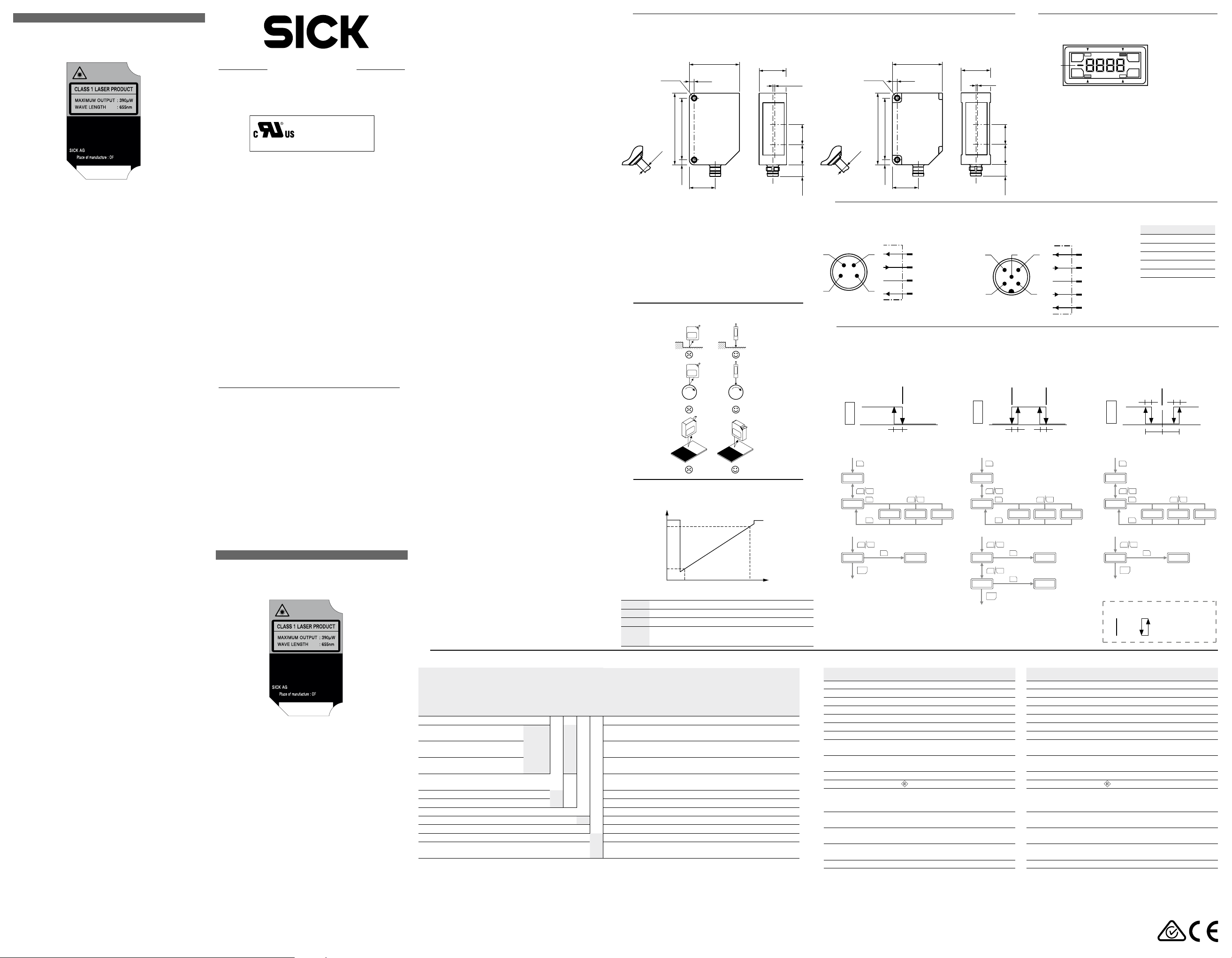
Distance sensor OD Mini Pro
with display and serial output
Operating Instructions
EN/IEC 60825-1:2014
Complies with 21 CFR 1040.10 and 1040.11
except for deviations pursuant to
Laser Notice No. 50, dated June 24, 2007
D-79183 Waldkirch, Germany
Manufactured in :
Laser radiation – Laser class 1
Identical laser class for issue EN/IEC 60825-1:2007
Safety notes
CAUTION: Use of controls or adjustments or performance
•
of procedures other than those specied herein may result in hazardous radiation exposure.
Read the Operating Instructions before starting opera-
•
tion.
Connection, mounting and setting must be performed by
•
qualied personnel.
Protect devices from moisture and contamination during
•
commissioning.
Not free of paint-wetting impairment substances.
•
No safety component pursuant to EU directive.
•
Intended use
The distance sensor OD Mini Pro is an optoelectronic sensor
and is used for optical determination of object distances
without contact.
Scope of delivery
Sensor OD Mini Pro, 2x M3 screws, laser warning label and
Operating Instructions
Commissioning
! Mount sensor.
— For steps, eccentricity measurements of round
objects and strong contrast changes, consider the
preferred direction of the sensor. See Fig. C.
" Align sensor.
— Align sensor so that object is within measuring range.
See Tab. G. Display indicates distance from center of
measuring range. If 9999 is displayed, measurement
is not possible. Object may be out of measuring
range.
§ Electrical connection: Connect cable socket tension free
and tighten the screw. See Fig. E.
$ Connect sensor to supply voltage. Operating display is
lit. Consider warm-up time for best measuring results.
See Tab. G.
% Perform parameterization. See Fig. H and Tab. I/J.
Operation via operating keys
The result of the taught-in switching behaviour can be queried via the serial interface (see table J for details).)
Perform teach-in (see Fig. F, Fig. H and Tab. I)
! Align distance sensor with the distance to be taught-in.
" Select teach option via parameter MoDE and teach-in
switching point:
— 1Pt (1-point teach): Switching point FAr. See Fig. F1.
— 2Pt (2-point teach): Switching point nEAr and FAr.
See Fig. F2.
— Obsb (background): Switching point ObSb.
See Fig. F3.
§ If necessary, enter hysteresis (hYst) and tolerance (tol).
See Fig. H and Tab. I.
Zeroing
The distance sensor is in RUN mode.
Set value to zero: Press key ZERO/RUN for 2 seconds.
•
The display shows 0.00 when successfully reset.
Recover value: Press key ZERO/RUN for 4 seconds.
•
Key lock (see Fig. H)
The distance sensor is in RUN mode.
On: Press – and + key for 3 seconds simultaneously.
•
O: Press – and + key for 3 seconds simultaneously.
•
Maintenance
It is recommended to regularly clean the external lens
surfaces and to check the screw connections and plug
connections.
8017923/ZMO9/2017-06/HS_8M
OD Mini Pro
NFPA79 applications only.
Adapters providing field
as marked on device
Australia
Phone +61 3 9457 0600
Austria
Phone +43 22 36 62 28 8-0
Belgium/Luxembourg
Phone +32 2 466 55 66
Brazil
Phone +55 11 3215-4900
Canada
Phone +1 905 771 14 44
Czech Republic
Phone +420 2 57 91 18 50
Chile
Phone +56 2 2274 7430
China
Phone +86 20 2882 3600
Denmark
Phone +45 45 82 64 00
Finland
Phone +358-9-2515 800
France
Phone +33 1 64 62 35 00
Germany
Phone +49 211 5301-301
Hong Kong
Phone +852 2153 6300
Hungary
Phone +36 1 371 2680
India
Phone +91 22 6119 8900
Israel
Phone +972 4 6881000
Italy
Phone +39 02 274341
Japan
Phone +81 3 5309 2112
Malaysia
Phone +6 03 8080 7425
Mexico
Phone +52 (472) 748 9451
Netherlands
Phone +31 30 2044 000
Please find detailed addresses and further locations in all major industrial
nations at www.sick.com
SICK AG | Erwin-Sick-Str. 1 | 79183 Waldkirch | Germany | www.sick.com
Irrtümer und Änderungen vorbehalten
Distanzsensor OD Mini Pro
mit Display und serieller Schnittstelle
Complies with 21 CFR 1040.10 and 1040.11
Laserstrahlung – Laserklasse 1
Identische Laserklasse für Ausgabe EN/IEC 60825-1:2007
Sicherheitshinweise
Vor allen Arbeiten die Betriebsanleitung lesen.
•
Anschluss, Montage und Einstellung nur durch Fachper-
•
sonal.
Gerät bei Inbetriebnahme vor Feuchte und Verunreinigung
•
schützen.
Nicht frei von lackbenetzungsstörenden Substanzen.
•
Kein Sicherheitsbauteil gemäß EU-Maschinenrichtlinie.
•
Bestimmungsgemäße Verwendung
Der Distanzsensor OD Mini Pro ist ein optoelektronischer
Sensor und wird zur optischen, berührungslosen Distanzmessung eingesetzt.
Lieferumfang
OD Mini Pro Sensor, Befestigungswinkel, 2x M3 Schrauben,
Laserwarnschild und Betriebsanleitung
Inbetriebnahme
! Sensor montieren.
— Bei Stufen, Exzentrizitätsmessungen von runden Ob-
" Sensor ausrichten.
jekten und bei starken Kontrastwechseln Vorzugsrichtung des Sensors beachten. Siehe Abb. C.
wiring leads are available.
Refer to the product information.
New Zealand
Phone +64 9 415 0459
Norway
Phone +47 67 81 50 00
Poland
Phone +48 22 539 41 00
Romania
Phone +40 356 171 120
Russia
Phone +7 495 775 05 30
Singapore
Phone +65 6744 3732
Slovakia
Phone +421 482 901201
Slovenia
Phone +386 591 788 49
South Africa
Phone +27 11 472 3733
South Korea
Phone +82 2 786 6321
Spain
Phone +34 93 480 31 00
Sweden
Phone +46 10 110 10 00
Switzerland
Phone +41 41 619 29 39
Taiwan
Phone +886 2 2375-6288
Thailand
Phone +66 2645 0009
Turke y
Phone +90 216 528 50 00
United Arab Emirates
Phone +971 4 88 65 878
United Kingdom
Phone +44 1727 831121
USA
Phone +1 800 325 7425
Vietnam
Phone +84 945452999
Subject to change without notice
Deutsch
Betriebsanleitung
EN/IEC 60825-1:2014
except for deviations pursuant to
Laser Notice No. 50, dated June 24, 2007
D-79183 Waldkirch, Germany
Manufactured in :
BZ int47
— Das Objekt muss im Messbereich liegen. Siehe
Tab. G. Das Display zeigt den Abstand von der Mess-
bereichsmitte an. Wird 9999 angezeigt, ist keine Messung möglich. Objekt liegt z. B. außerhalb des Mess-
bereiches.
§ Elektrischer Anschluss: Leitungsdose spannungsfrei aufstecken und festschrauben. Siehe Abb. E.
$ Sensor an Versorgungsspannung legen. Betriebsanzeige
leuchtet. Für optimale Messergebnisse Aufwärmzeit be-
Dimensions / Abmessungen
A
OD1-xxxxHxxxxx
Edelstahl/Stainless steel
31
3
2 x M3
(0.12)
(1.22)
17
(0.67)
2
achten. Siehe Tab. G.
% Parametrierung durchführen. Siehe Abb. H und Tab. I/J.
Bedienung über Bedientasten
Das Ergebnis des eingelernten Schaltverhaltens kann über
die serielle Schnittstelle abgefragt werden. (Details siehe
Tab. J)
Teach-in durchführen (siehe Abb. F, Abb. H und Tab. I)
! Distanzsensor auf einzulernende Distanz ausrichten.
" Teach-Option über Parameter MoDE wählen und Schalt-
punkt einlernen:
— 1Pt (1-Punkt-Teach): Schaltpunkt FAr. Siehe Abb. F1.
— 2Pt (2-Punkt-Teach): Schaltpunkt nEAr und FAr. Sie-
he Abb. F2.
— Obsb (Hintergrund): Schaltpunkt ObSb. Siehe Abb. F3.
§ Ggf. Hysterese (hYst) und Toleranz (tol) eingeben. Siehe
Abb. H und Tab. I.
Nullpunktverschiebung
Der Distanzsensor bendet sich im RUN-Mode.
Wert auf Null setzen: Taste ZERO/RUN für 2 Sekunden
•
drücken. Bei erfolgreicher Rücksetzung zeigt das Display
0.00 an.
Wert wieder herstellen: Taste ZERO/RUN für 4 Sekunden
•
drücken.
Tastensperre (siehe Abb. H)
1
Ø 4.5
(0.18)
44.4 (1.75)
38.2 (1.50)
3.1
(0.12)
16
(0.63)
All dimensions in mm (inch)
Type with 30 cm cable with M12, 5 pin connector /
Variante mit Anschlussleitung 30 cm mit Stecker M12, 5-pin
Optical axis / Optische Achse
Distance optical axis sender to receiver /
Abstand optische Achse Sender zu Empfänger:
OD1-B015x: 8.1 mm / OD1-B35x: 12.6 mm
/
OD1-B100x: 15.5 mm
Optical axis receiver / Optische Achse Empfänger
Optical axis sender / Optische Achse Sender
Preferred mounting direction /
C
Vorzugsrichtung der Sensormontage
Der Distanzsensor bendet sich im RUN-Mode.
Ein: Taste – und + gleichzeitig für 3 Sekunden drücken.
•
Aus: Taste – und + gleichzeitig für 3 Sekunden drücken.
•
Wartung
Es wird empfohlen in regelmäßigen Abständen die optischen
Grenzächen zu reinigen und Verschraubungen, sowie Steckverbindungen zu überprüfen.
Measurement value scaling /
D
Messwertskalierung
value
in Hex
7FFF
2
1
Near end
of measuring
Model OD1-B015x05xxx OD1-B035x15xxx OD1-B100x50xxx
Range ±5mm ±15mm ±50mm
Unit 1μm 10μm 10μm
Technical Data / Technische Daten
G
OD1-
Data
(Hex)
Resolution 1)Repeatability
Auösung
1)
EC78h
1388h2FA24h105DCh2EC78h11388h
1
1), 2)
Linearity
Linearität
1), 2)
Reproduzierbarkeit
Measuring range /Messbereich
15 ± 5 mm B015 05 1 μm 3 μm ± 10 μm 700 μm x 500 μm
35 ± 15 mm B035 15 6 μm 9 μm ± 30 μm 800 μm x 450 μm
100 ± 50 mm B100 50 20 μm 30 μm ± 100 μm 700 μm x 600 μm
Housing material /
Gehäusematerial
Stainless steel / Edelstahl H
Aluminum / Aluminium C
Interface / Schnittstelle
RS-485 A1
Connection / Anschluss
M8 plug, 4-pin / M8-Stecker, 4-polig 4
Cable with M12 plug, 5-pin /
Leitung mit M12-Stecker, 5-polig
1)
At set averaging 512
2)
Constant ambient conditions
3)
Measurement on 90 % remission (ceramic, white)
4)
For best performance consider warm up time ≤ 5 min.
5
1)
Bei Mittelwerteinstellung 512
2)
Konstante Rahmenbedingungen
3)
Messung auf 90 % Remission (Keramik, weiß)
4)
Für optimale Messergebnisse max. Aufwärmzeit von 5 Min. beachten.
Far end of
measuring
3), 4
Typ. light spot
dimension
(Distance)
3), 4
Typ. Lichteckabmessung (Distanz)
(15 mm)
(35 mm)
(100 mm)
Distance
OD1-xxxxCxxxxx
Aluminium/Aluminum
1.1
(0.04)
2 x M3
31
3
(0.12)
(1.22)
17,8
(0.7)
2
4
3 3
5
12.5
(0.49)
7.1
(0.28)
1
Ø 4.5
Electrical connection / Elektrischer Anschluss
E
(0.18)
44.4 (1.75)
38.2 (1.50)
3.1
(0.12)
16
(0.63)
OD1-Bxxxxxxx1x
M8, 4-pin
4
3
Switching behavior / Schaltverhalten
F
wht
blu
blk
L+ (12 V ... 24 V)
2
RS-485 (B)
3
0 V
4
RS-485 (A)
1
brn
The result of the taught-in switching behaviour can be queried via the serial interface (see table J for details). / Das
Ergebnis des eingelernten Schaltverhaltens kann über die serielle Schnittstelle abgefragt werden (Details siehe Tab. J)
F1
ModE: 1Pt
OD
Min Max
RUN Mode
SET
hYSt
FAr
1
MEnu
–
+
SET
ModE
2Pt
SET
FAr
ZERO
RUN
RUN Mode
–
+
SET
Teach-in current
distance
–
1pt
tch
+
obSb
F2
ModE: 2Pt
OD
RUN Mode
MEnu
ModE
nEAr
FAr
RUN Mode
2
OD1-
Light source Laser, red
Laser protection class
Response time
Measuring frequency 2 kHz / 1 kHz / 500 Hz / 250 Hz / Auto
Supply voltage V
Power consumption ≤ 1,92 W (without load, incl. current output)
Warm up time ≤ 5 min
Material Housing: stainless steel or aluminum,
Weight with stainless steel housing: 70 g,
Enclosure rating IP 67
Protection class
Ambient temperature Operation: –10 … +50 °C at rel. humidity
Typ. ambient light safety Articial light: ≤ 3.000 lx;
Temperature drift ± 0.08 % FS/K (FS: Full Scale: Measuring
Vibration resistance 10 … 55 Hz (Amplitude 1,5 mm; x-, y- and
Shock resistance 50 G (x-, y- and z-axis 3 times each)
1)
Wavelength 655 nm, max. output: 390 μW
2)
At xed sensitivity setting and averaging =1
3)
Sampling rate 500µs: 2 ... 7.5 ms response time/ sampling rate 1000µs:
4 ... 15 ms response time
4)
When using analog voltage output reduced to DC 18 V (–5 %) … DC 24 V
(+ 10 %)
1)
2)
4)
S
1 (EN 60825-1)
2 ms / 4 ms / 8 ms / 16 ms / Auto
12 V DC (–5 %) … 24 V DC (+10 %)
Front window: PPSU
with aluminum housing: 40 g
35 % ... 95 % (not condensing)
Storage: –20 … +60 °C
Sunlight: ≤ 10.000 lx
range of sensor)
z-axis 2 hours each)
Display and operating elements /
B
Display und Bedienelemente
5
1.1
(0.04)
Status switching output /
1
Status Schaltausgang
4
5
12.5
(0.49)
7.1
(0.28)
OD1-Bxxxxxxx2x
M12, 5-pin
4
5
12
12
nEArFAr
Min Max
hYSt hYSt
SET
–
+
SET
2Pt
SET
Teach-in current
distance
SET
Teach-in current
distance
SET
OD1-
Lichtsender Laser, rot
Laserschutzklasse
Ansprechzeit
Messfrequenz 2 kHz / 1 kHz / 500 Hz / 250 Hz / Auto
Versorgungsspannung U
Leistungsaufnahme ≤ 1,92 W (ohne Last, inkl. Stromausgang)
Aufwärmzeit ≤ 5 min
Material Gehäuse: Edelstahl oder Aluminium,
Gewicht mit Edelstahlgehäuse: 70 g,
Schutzart IP 67
Schutzklasse
Umgebungsbedingungen Betrieb: –10 … +50 °C bei rel. Feuchte
Fremdlichtsicherheit Künstliches Licht: ≤ 3.000 lx;
Temperaturdrift ± 0,08 % FS/K (FS: Full Scale: Messbereich
Vibrationsfestigkeit 10 … 55 Hz (Amplitude 1,5 mm; x-, y- und
Stoßfestigkeit 50 G (x-, y- und z-Achse jeweils 3 Mal)
1)
2)
3)
4)
ZERO
RUN
–
+
–
+
3)
Status zeroing /
2
Status Nullpunktverschiebung
Status Teach mode /
3
Status Teach-Modus
Status laser
4
Status Laser
Minus sign for measured value indicator /
5
brn
3
wht
blu
blk
–
+
1pt
obSb
tch
tch
2)
Wellenlänge 655 nm, max. Leistung: 390 μW
Bei xer Empndlichkeitseinstellung und Mittelwertbildung =1
Messrate 500µs: 2 … 7,5 ms Ansprechzeit/Messrate 1000µs: 4 … 15 ms
Ansprechzeit
Bei Nutzung des analogen Spannungsausganges reduzierte Grenzen auf
DC 18 V (–5 %) … DC 24 V (+ 10 %)
ZERO
RUN
SET
1
2
3
4
5gra
1)
1
OUT
2
ZERO
+
–
LASER
MANUAL
34
brn brown braun
wht white weiß
blu blue blau
blk black schwarz
RS-485 (B)
0 V
RS-485 (A)
nc
F3
V
gra grey grau
1 not connected
nicht belegt
ModE: obSb
hYSt
OD
Min Max
RUN Mode
SET
MEnu
–
ModE
–
obSb
ZERO
RUN
RUN Mode
Switching
point
1 (EN 60825-1)
2 ms / 4 ms / 8 ms / 16 ms / Auto
4)
12 V DC (–5 %) … 24 V DC (+10 %)
Frontscheibe: PPSU
mit Aluminiumgehäuse: 40 g
35 % ... 95 % (nicht kondensierend)
Lagerung: –20 … +60 °C
Sonnenlicht: ≤ 10.000 lx
des Sensors)
z-Achse jeweils 2 Stunden)
+
SET
SET
+
Hysteresis
tol
2Pt
SET
1
obSb
hYSt
tol
–
1pt
Teach-in current
distance
tch
1
1. Teach-in point
2
2. Teach-in point
+
obSb
3)
Page 2
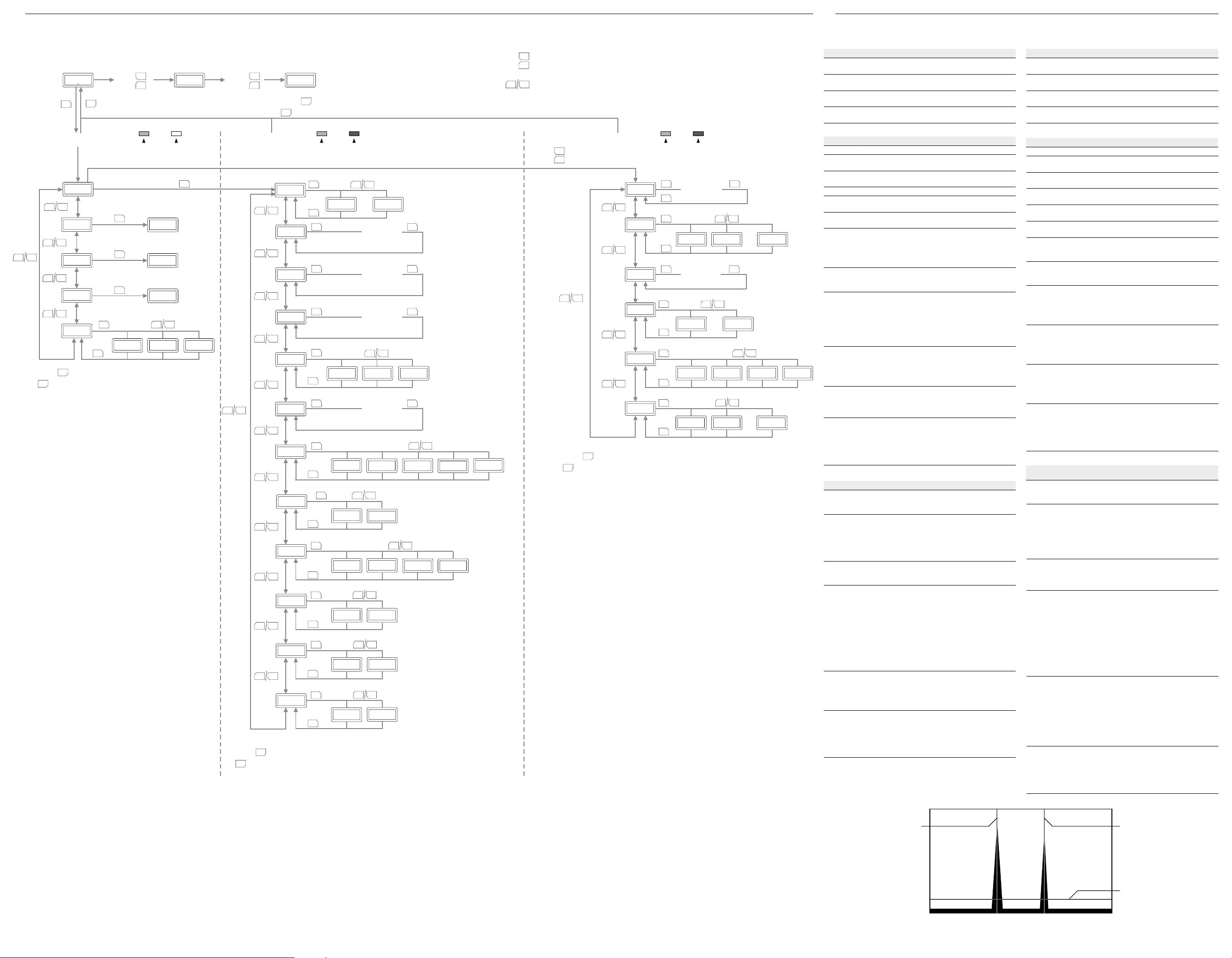
Menu overview / Menüübersicht
11
2
H
RUN mode
5000
ZERO
SET
RUN
Teach-in mode
MEnu
–
+
nEAr
–
+
–
+
Press key to return to Run mode.
ZERO
RUN
FAr
–
+
obSb
–
+
SET
ModE
SET
ZERO
RUN
-Taste drücken, um zum Run-Modus zurückzugelangen.
3 s
SET
SET
SET
+
–
2Pt
Loc
LASER MANUAL
SET
Teach-in current
distance
tch
Teach-in current
distance
tch
Teach-in current
distance
tch
–
+
1pt
obSb
+
Press “+” and “–” key simultaneously.
–
“+” und “–”-Taste gleichzeitig drücken.
+
3 s
–
Setting mode Expert mode
–
–
–
–
uLoc
ZERO
Press key to return to Run mode.
RUN
ZERO
-Taste drücken, um zum Run-Modus zurückzugelangen.
RUN
LASER MANUAL LASER MANUAL
+
+
+
+
bAud
SET
SET
SET
nEAr
SET
FAr
SET
obSb
SET
–
+
...
Enter value
via +/–
Enter value
via +/–
Enter value
via +/–
–
12509.6
SET
SET
SET
+
Press “+” or “–” key.
–
+
“+” oder “–”-Taste.
> 2 s
+
–
–
–
–
+
–
ModE
2Pt
–
+
–
+
–
+
SET
SET
tol
SET
1pt
Enter value
via +/–
SAMP
–
+
SET
500
SET
1000
–
+
obSb
SET
–
2000
–
+
ZERO
Press key to return to Run mode.
RUN
4000
Auto
ZERO
-Taste drücken, um zum Run-Modus zurückzugelangen.
RUN
Acti
L on
–
+
SET
SET
AVG
–
+
SET
SET
d on
–
+
1
–
8
64 512
+
ALrM
clmP hold
–
+
SET
SET
–
+
rESt
–
+
SET
SET
no
yES
–
+
diSP
SET
ZERO
Press key to return to Run mode.
RUN
ZERO
-Taste drücken, um zum Run-Modus zurückzugelangen.
RUN
on
oFF
+
+
+
+
hYSt
SEnS
2Ero
hdct
thrE
MToP
SET
Enter value
via +/–
SET
SET
Auto
SET
SET SET
Enter value
–
via +/–
SET
SET
SET
SET
SET
SET
–
+
0000
bASE
...
P100 P200
–
MAH Pt1 Pt5...
SET
+
9999
–
+
Parameter description / Parameterbeschreibung
I
1
Parameter Teach-in mode
Select the parameter MoDE teaching-in.
Parameter Description Default
nEAr
(Near)
FAr
(Far)
ObSb Teach-in current distance as background
MoDE
(Mode)
Teach-in current distance to the object as
near switching point. See Fig. F.
Teach-in current distance to the object as
far switching point. See Fig. F.
(ObSb). See Fig. F3.
Select function mode: 2Pt (2-point), 1Pt
(1-point) or ObSb (background)
–1 / –3 /
–10 mm
+1 / +3 /
+10 mm
0
2Pt
Parameter Setting mode
Parameter Description Default
bAud Set the baud rate. 9.6 kBaud
nEAr
(Near)
FAr
(Far)
ObSb Set distance for ObSB mode. See Fig. F3. 0
MoDE
(Mode)
tol
(Tolerance)
SAMP
M__6M__1 ...
+
(Sampling)
Acti Select switching output behavior:
AVG
(Average)
ALrM
(Alarm)
P400
rESt
(Reset)
diSP
(Display)
Set distance for near switching point.
See Fig. F.
Set distance for far switching point.
See Fig. F.
Select function mode: 2Pt (2-point), 1Pt
(1-point) or ObSb (background)
Set tolerance around the teaching point
in the ObSB mode. See Fig. F3.
Select sampling rate (measuring frequency):
500 µs (2 kHz), 1000 µs (1 kHz),
2000 µs (500 Hz), 4000 µs (250 Hz),
Auto
• L on: Light on (light-switching)
• d on: Dark on (dark-switching)
Select moving averaging:
• 1: Average across 1 measured value
• 8: Average across 8 measured values
• 64: Average across 64 measured
values
• 512: Average across 512 measured
values
Select behavior of the output if no sudden measurement is possible.
• hold: Continue to output last valid
measured value.
• cLMP (Clamp): Output 24 mA/16 V.
Perform reset. The function of the switching output (PNP/NPN) is not reset.
• no: Do not perform reset.
• YES: Perform reset.
Select behavior of the display if the key
lock is active.
• on: The display remains on with the
key lock active.
• oFF: The display is switched o with
the key lock active.
–1 / –3 /
–10 mm
+1 / +3 /
+10 mm
2Pt
1 / 3 /
10 mm
500 µs
(2 kHz)
L on
64
cLMP
no
on
Parameter Expert mode
Parameter Description Default
hYSt
(Hysteresis)
SEnS
(Sensitivity)
ZEro Manual zeroing as distance to measuring
hdct Set holding time: 0 … 9999
tHrE Set threshold level:
NtoP Dene barycenter:
1) Type-dependent OD1-B015x05xxx/OD1-B035x15xxx/OD1-B100x50xxx
I2 Illustration for parameters tHrE and NtoP/Darstellung
für Parameter tHrE und NtoP
Set hysteresis for the switching output.
See Fig. F3.
Select sensitivity:
• Auto: Automatic sensitivity setting
• n__1: Minimum sensitivity within the
sampling rate
• n__6: Maximum sensitivity within the
sampling rate
range center. This value is adjusted
automatically with zeroing.
Holding time: Set sampling rate (SAMP) x
set value hdct
• 0: The last valid value is kept unli-
mited.
• At setting ALrM (Alarm) = hold, the last
valid measured value is held for the
time set here (hdct).
• At setting ALrM (Alarm) = cLMP
(Clamp), the parameter hdct is deactivated.
• base: Set threshold to lowest level.
• P400: Set threshold to upper level.
• P200: Set threshold to middle level.
• P100: Set threshold to lower level.
• Max: Maximum distance
• Pt5: 5th point from sensor side.
• Pt4: 4th point from sensor side.
• ...
• Pt1: Closest point from sensor side.
*
0.05 /
0.15 /
0.5 mm
Auto
0 mm
0
bASE
MAH
Parameter Teach-in-Modus
Vor dem Einlernen der Parameter MoDE wählen.
1)
Parameter Beschreibung Default
nEAr
(Near)
FAr
(Far)
ObSb
MoDE
(Mode)
Aktuelle Distanz zum Objekt als nahen
Schaltpunkt einlernen. Siehe Abb. F.
Aktuelle Distanz zum Objekt als fernen
Schaltpunkt einlernen. Siehe Abb. F.
)
Aktuelle Distanz als Hintergrund (ObSb)
einlernen. Siehe Abb. F3.
Funktions-Modus wählen: 2Pt (2-Punkt),
1Pt (1-Punkt) oder ObSb (Hintergrund)
Parameter Einstellmodus
1)
Parameter Beschreibung Default
bAud Baudrate einstellen.. 9.6 kBaud
nEAr
(Near)
FAr
(Far)
ObSb Distanz für ObSB-Modus einstellen. Siehe
MoDE
(Mode)
tol
(Toleranz)
SAMP
(Sampling)
Acti Schaltausgangsverhalten wählen:
AVG
(Average)
ALrM
(Alarm)
rESt
(Reset)
diSP
(Display)
Distanz für nahen Schaltpunkt einstellen.
Siehe Abb. F.
Distanz für fernen Schaltpunkt einstellen.
Siehe Abb. F.
Abb. F3.
Funktions-Modus wählen: 2Pt (2-Punkt),
1Pt (1-Punkt) oder ObSb (Hintergrund)
Toleranz um den Teach-Punkt im ObSB-
Modus einstellen. Siehe Abb. F3.
Messrate (Messfrequenz) wählen:
500 µs (2 kHz), 1000 µs (1 kHz),
2000 µs (500 Hz), 4000 µs (250 Hz), Auto
• L on: Light on (hellschaltend)
• d on: Dark on (dunkelschaltend)
Gleitende Mittelwertbildung wählen:
• 1: Mittelung über 1 Messwert
• 8: Mittelung über 8 Messwerte
• 64: Mittelung über 64 Messwerte
• 512: Mittelung über 512 Messwerte
Verhalten des Ausgangs wählen, wenn
keine Messung möglich ist.
• hold: Letzten gültigen Messwert weiter-
hin ausgeben (Halten).
• cLMP (Clamp): 24 mA/16 V ausgeben.
Reset durchführen. Die Funktion des
Schaltausgangs (PNP/NPN) wird nicht
zurückgesetzt.
• no: Kein Reset durchführen.
• YES: Reset durchführen.
Verhalten des Displays wählen, wenn die
Tastensperre aktiviert ist.
• on: Bei aktivierter Tastensperre bleibt
das Display eingeschaltet.
• oFF: Bei aktivierter Tastensperre wird
das Display ausgeschaltet.
Parameter Experten Modus
Parameter Beschreibung
1)
hYSt
(Hysterese)
SEnS
(Sensitivity)
ZEro Manuelle Nullpunkteinstellung als Distanz
hdct Haltezeit einstellen: 0 … 9999
tHrE Grenzwert einstellen:
NtoP Lichtschwerpunkt denieren:
1) Typabhängig OD1-B015x05xxx/OD1-B035x15xxx/OD1-B100x50xxx
Hysterese für Schaltausgang einstellen.
Siehe Abb. F3.
Empndlichkeit wählen:
• Auto: Automatische Empndlichkeitsein-
stellung
• n__1: Minimale Empndlichkeit innerhalb
der Messrate
• n__6: Maximale Empndlichkeit inner-
halb der Messrate
zur Messbereichsmitte. Mit Ausführung
einer Nullpunktverschiebung wird dieser
Wert automatisch angepasst.
Haltezeit: Eingestellte Messrate (SAMP) x
eingestellter Wert hdct
• 0: Letzter gültiger Wert wird unbegrenzt
gehalten.
• Bei Einstellung ALrM (Alarm) = hold, wird
der zuletzt gültige Messwert für die hier
eingestellte Zeit (hdct) gehalten.
• Bei Einstellung ALrM (Alarm) = cLMP
(Clamp), ist der Parameter hdct deaktiviert.
• base: setzte Grenzwert auf niedrigstes
Level.
• P400: setzte Grenzwert auf höchstes
Level.
• P200: setzte Grenzwert auf mittleres
Level.
• P100: setzte Grenzwert auf niedriges
Level.
• Max = Maximale Distanz.
• Pt5 = 5ter Punkt von der Sensorseite.
• Pt4 = 4ter Punkt von der Sensorseite.
• ...
• Pt1 = Nächster Punkt zum Sensor.
–1 / –3 /
–10 mm
+1 / +3 /
+10 mm
0
2Pt
–1 / –3 /
–10 mm
+1 / +3 /
+10 mm
0
2Pt
1 / 3 /
10 mm
500 µs
(2 kHz)
L on
64
cLMP
no
on
Default
1)
0.05 /
0.15 /
0.5 mm
Auto
0 mm
0
bASE
MAH
1)
1)
Example for two signal peaks/ Beispiel für zwei Signalspitzen:
1 Ntop: Measured barycenter/Gemessener Lichtschwerpunkt (Pt_1/Pt_2)
2 thrE: Set threshold level / Grenzwert einstellen
* The picture shows the light
distribution on the receiver chip
of the sensor and the working
principle for the parameters tHrE
and NtoP – the light distribution
can't be read out with OD Mini
Pro. /
Das Bild zeigt die Licht verteilkurve auf der Empfangszeile des
Sensors und das Funktionsprinzip
für die Parameter tHrE und NtoP
– die Lichtverteilkurve kann beim
OD Mini Pro nicht ausgelesen
werden.
Page 3

Communication (English)
J
Communication method RS-485 Half Duplex (Multi-drop protocol is not supported)
Transmission code Binary
Data length 8bit
Stop length 1bit
Parity check Nil
Baud rate (bps) 9.6k / 19.2k / 38.4k / 57.6k / 115.2k / 230.4k / 312k / 460k / 500k / 625k / 833k / 920k /
Data classication STX / ETX
1.25M
J1 Data Format / Data Format
• Transmission data
STX COMMAND DATA1 DATA2 ETX BCC
• Incoming data
STX ACK RESPONSE1 RESPONSE2 ETX BCC
• Incomming data (error)
STX NAK ERROR CODE 00H ETX BCC
STX = 02H , ETX = 03H , ACK = 06H , NAK = 15H , BCC = XOR of values hatched
J2 Basic Commands
Command Description
C(43H) Reading out Measurement value / Output status
W(57H) Writing the setting
R(52H) Reading out setting
J3 Error code table
Error code Description
02H Address is invalid
04H BCC value is invalid
05H Invalid command is issued except "C", "W", "R"
06H Setting value is invalid (out of specications)
07H Setting value is invalid (out of range)
J4 C(43H) parameter table (Reading out Measurement value/Output status)
Command Type DATA1 (upper) DATA2 (lower) Description
Reading out Measurement value Write B0h 01h
Read Upper data Lower data Response in 2 bytes
Reading out Output status Write B0h 02h
Writing the setting Write A0h 00h Write the setting into EEPROM. The setting will be dissa-
Dismissing the setting Write A0h 01h Dismiss the setting and set the parameters to previous value
Teaching ObSB Write 11h 05h
Teaching near side point Write 11h 06h
Teaching far side point Write 11h 07h
Laser ON Write A0h 03h
Laser OFF Write A0h 02h
Execute Zero reset Write A1h 00h
Release Zero reset Write A1h 01h
Execute Key lock Write A1h 04h
Release Key lock Write A1h 05h
Initializing Write 40h 00h Initialize all parameters except communication speed and
1) Measurement value is described as following.
Model OD1-B015x05xxx OD1-B035x15xxx OD1-B100x50xxx
Range ±5mm ±15mm ±50mm
Unit 1μm 10μm 10μm
Data (Hex) EC78h 1388h FA24h 05DCh EC78h 1388h
Data (Decimal) -5000 +5000 -1500 +1500 -5000 +5000
Read 00h Output status bit:0 = 1 (ON)
Read 00h 00h
Read 00h 00h
Read 00h 00h
Read 00h 00h
Read 00h 00h
Read 00h 00h
Read 00h 00h
Read 00h 00h
Read 00h 00h
Read 00h 00h
Read 00h 00h
Read 00h 00h
bit:4 = 0 (the status has been read)
peared if this command is not done.
back.
re-boot. The communication won't worrk while initializing.
1)
J5 Setting parameter table
Setting Address/
Model type Address 01h 00h Return center value of measurement range (only for
Measurement
mode
Near side threshold Address 41h 00h
Far side threshold Address 41h 02h
ObSB threshold Address 41h 04h
ObSB hysteresis Address 41h 06h
Output polarity Address 40h 08h
Sampling period Address 40h 06h
Averaging number Address 40h 0Ah
Alarm setting Address 40h 0Ch
Alarm - Hold and
Clamp
Parameter
Parameter 00h 0Fh / 23h / 64h 15mm type / 35mm type / 100mm type
Address 40h 04h
Parameter 00h 00h / 01h / 02h 2 point Teaching / 1 point Teaching / ObSB Teaching
Parameter Upper data Lower data
Parameter Upper data Lower data
Parameter Upper data Lower data
Parameter Upper data Lower data
Parameter 00h 00h Light ON: ON when exceeds the threshold
Parameter 00h 00h / 01h / 02h / 03h / 04h 500μs / 1,000μs / 2,000μs / 4,000μs / AUTO
Parameter 00h 00h / 01h / 02h / 03h Once / 8 times / 64 times / 512 times
Parameter 00h 00h / 01h Clamp / Hold
Address 41h 08h
Parameter Upper data Lower data
DATA1 (upper) DATA2 (lower) Description
checking model type)
00h 01h Dark ON: ON when less than the threshold
Setting Address/
Display setting Address 40h 0Eh
Hysteresis Address 41h 10h
Threshold Address 40h 12h
Zero shift Address 41h 12h
Sensitivity Address 40h 14h
* Execute the command "R" (Read out) before executing command "W" (Write).
Examples (English)
K
K
Example: Writing Data – General Procedure
1
Writing is done as following proceedure.
1. Read out setting
Execute Command "R" (Reading out setting) on the target parameter. Set "Address" at "DATA1" and "DATA2".
2. Write setting
Execute Command "W" (Writing the setting) on the target parameter. Writing data is done to the address set at "1. Read setting".
3. Write to EEPROM (see J
K
Example: Setting "Sampling period" to "AUTO" (see J5)
2
1. Read out "Sampling period"
Transmission command: STX (02h) R (52h) 40h 06h ETX (03h) BCC (14h)
Incoming data: STX (02h) ACK (06h) 00h 00h ETX (03h) BCC (06h)
2. Write the setting
Transmission command: STX (02h) W (57h) 00h 04h ETX (03h) BCC (53h)
Incoming data: STX (02h) ACK (06h) 00h* 00h* ETX (03h) BCC (06h)
* Incoming data of command "W" (Writing the setting) will be "00h" and "00h".
3. Write to EEPROM
Transmission command: STX (02h) C (43h) A0h 00h ETX (03h) BCC (E3h)
Incoming data: STX (02h) ACK (06h) 00h 00h ETX (03h) BCC (06h)
K
Example: Setting "Far threshold" + 1 mm with OD1-*35 type
3
1. Read out "Far side threshold"
Transmission command: STX (02h) R (52h) 41h 00h ETX (03h) BCC (13h)
Incoming data: STX (02h) ACK (06h) FEh D4h ETX (03h) BCC (2Ch)
2. Write the setting
Transmission command: STX (02h) W (57h) 00h 64h ETX (03h) BCC (33h)
Incoming data: STX (02h) ACK (06h) 00h 00h ETX (03h) BCC (06h)
3. Write to EEPROM
Transmission command: STX (02h) C (43h) A0h 00h ETX (03h) BCC (E3h)
Incoming data: STX (02h) ACK (06h) 00h 00h ETX (03h) BCC (06h)
K
Example: Read out measurement data*
4
Transmission command: STX (02h) C (43h) B0h 01h ETX (03h) BCC (F2h)
Incoming data: STX (02h) ACK (06h) FCh 6Fh ETX (03h) BCC (95h)
*example with OD1-B035x15xxx/ measuring value = –9.13 mm
K
Example: Errorcode for Laser ON
5
Command with WRONG check sum:
Transmission command: STX (02h) C (43h) A0h 03h ETX (03h) BCC (E2h)
Incoming data: STX (02h) NAK (15h) 04h* 00h ETX (03h) BCC (11h)
*BCC invalid (see J
Command with RIGHT check sum:
Transmission command: STX (02h) C (43h) A0h 03h ETX (03h) BCC (E0h)
Incoming data: STX (02h) ACK (06h) 00h 00h ETX (03h) BCC (06h)
Parameter
Parameter 00h 00h / 01h ON / OFF
Parameter Upper data Lower data
Parameter 00h 00h / 01h / 02h / 03h Base: Lowest level / Level 400: Upper level / Level
Parameter Upper data Lower data
Parameter 00h 00h AUTO
).
4
)
3
DATA1 (upper) DATA2 (lower) Description
200: middle level / Level 100: lower level
00h 01h / 02h / 03h / 04h / 05h
/ 06h
6: Maximum sensitivity / 5 / 4 / 3 / 2 / 1: Minimum
sensitivity
Page 4

Kommunikation (Deutsch)
J
Kommunikationsmethode RS-485 Halbduplex (Multidrop-Protokoll wird nicht unterstützt)
Sendecode binär
Datenlänge 8 Bit
Stoppbitlänge 1 Bit
Paritätskontrolle Null
Baudrate (bps) 9,6k / 19,2k / 38,4k / 57,6k / 115,2k / 230,4k / 312k / 460k / 500k / 625k / 833k / 920k /
Datenklassizierung STX / ETX
J
Datenformat / Datenformat
1
• Sendedaten
STX BEFEHL DATEN1 DATEN2 ETX BCC
• Eingangsdaten
STX ACK ANTWORT1 ANTWORT2 ETX BCC
• Eingangsdaten (Fehler)
STX NAK FEHLERCODE 00H ETX BCC
1,25M
STX = 02H , ETX = 03H , ACK = 06H , NAK = 15H , BCC = XOR der schraerten Werte
J
Grundbefehle
2
Befehl Beschreibung
C(43H) Lesen des Messwerts / Ausgangsstatus
W(57H) Schreiben der Einstellung
R(52H) Lesen der Einstellung
J
Fehlercodetabelle
3
Fehlercode Beschreibung
02H Adresse ist ungültig
04H BBC-Wert ist ungültig
05H Ungültiger Befehl außer "C", "W", "R" wird ausgegeben
06H Einstellungswert ist ungültig (außerhalb der Spezikationen)
07H Einstellungswert ist ungültig (außerhalb des Bereichs)
J
C(43H) Parametertabelle (Lesen des Messwerts/Ausgangsstatus)
4
Befehl Typ
Lesen des Messwerts Schreiben B0h 01h
Lesen Obere Daten Untere
Lesen des Ausgangsstatus Schreiben B0h 02h
Schreiben der Einstellung Schreiben A0h 00h Einstellung in EEPROM schreiben. Die Einstellung geht bei
Verwerfen der Einstellung Schreiben A0h 01h Einstellung verwerfen und die Parameter auf vorherigen Wert
ObSB einlernen Schreiben 11h 05h
Nahen Schaltpunkt einlernen Schreiben 11h 06h
Fernen Schaltpunkt einlernen Schreiben 11h 07h
Laser AN Schreiben A0h 03h
Laser AUS Schreiben A0h 02h
Nullpunkt-Reset durchführen Schreiben A1h 00h
Nullpunkt-Reset aufheben Schreiben A1h 01h
Tastensperre aktivieren Schreiben A1h 04h
Tastensperre lösen Schreiben A1h 05h
Initialisierung Schreiben 40h 00h Initialisierung aller Parameter außer Kommunikationsge-
1) Messwert wird wie folgt beschrieben.
Modell OD1-B015x05xxx OD1-B035x15xxx OD1-B100x50xxx
Bereich ±5 mm ±15 mm ±50 mm
Einheit 1 μm 10 μm 10 μm
Daten (Hex) EC78h 1388h FA24h 05DCh EC78h 1388h
Daten (Dezimal) -5000 +5000 -1500 +1500 -5000 +5000
J
Einstellungsparametertabelle
5
Einstellung Adresse/
Modelltyp Adresse 01h 00h Mittelwert des Messbereichs zurückgeben (nur zur
Messmethode Adresse 40h 04h
Naher Schwellenwert
Ferner Schwellenwert
ObSB-Schwellenwert
ObSB-Hysterese Adresse 41h 06h
Ausgangspolarität Adresse 40h 08h
Abtastzeit Adresse 40h 06h
Mittelungszahl Adresse 40h 0Ah
Parameter
Parameter 00h 0Fh / 23h / 64h 15mm Typ / 35mm Typ / 100mm Typ
Parameter 00h 00h / 01h / 02h 2-Punkt-Teach / 1-Punkt-Teach / ObSB-Teach
Adresse 41h 00h
Parameter Obere Daten Untere Daten
Adresse 41h 02h
Parameter Obere Daten Untere Daten
Adresse 41h 04h
Parameter Obere Daten Untere Daten
Parameter Obere Daten Untere Daten
Parameter 00h 00h Hell AN: AN wenn der Schwellenwert überschritten wird
Parameter 00h 00h / 01h / 02h / 03h / 04h 500 μs / 1.000 μs / 2.000 μs / 4.000 μs / AUTO
Parameter 00h 00h / 01h / 02h / 03h Einmal / 8-mal / 64-mal / 512-mal
Lesen 00h Ausgangs-
Lesen 00h 00h
Lesen 00h 00h
Lesen 00h 00h
Lesen 00h 00h
Lesen 00h 00h
Lesen 00h 00h
Lesen 00h 00h
Lesen 00h 00h
Lesen 00h 00h
Lesen 00h 00h
Lesen 00h 00h
Lesen 00h 00h
DATEN1
(obere)
00h 01h Dunkel AN: AN wenn der Schwellenwert unterschritten
DATEN1
(obere)
DATEN2 (untere) Beschreibung
DATEN2
(untere)
Daten
status
Beschreibung
Antwort in 2 Bytes
Bit:0 = 1 (AN)
Bit:4 = 0 (der Status wurde gelesen)
einem Neustart verloren, wenn dieser Befehl nicht ausgeführt
wird.
zurücksetzen.
schwindigkeit und Neustart. Die Kommunikation funktioniert
nicht während der Initialisierung.
Prüfung des Modelltyps)
wird
1)
Einstellung Adresse/
Alarmeinstellung Adresse 40h 0Ch
Alarm - Hold und
Clamp
Displayeinstellung Adresse 40h 0Eh
Hysterese Adresse 41h 10h
Schwellenwert Adresse 40h 12h
Nullpunktverschiebung
Empndlichkeit Adresse 40h 14h
* Führen Sie den Befehl "R" (Lesen) aus, bevor Sie den Befehl "W" (Schreiben) ausführen.
Beispiele (Deutsch)
K
K
Beispiel: Übertragung von Daten – Allgemeine Methode
1
Der Ablauf der Übertragung sieht wie folgt aus.
1. Einstellung lesen
Befehl "R" (Einstellung lesen) für den Zielparameter ausführen. "Adresse" bei "DATEN1" und "DATEN2" einstellen.
2. Einstellung schreiben
Befehl "W" (Einstellung schreiben) für den Zielparameter ausführen. Die Daten werden an die bei "1 eingestellte Adresse schreiben. Einstellung
lesen".
3. In EEPROM schreiben (siehe J
K
Beispiel: "Abtastzeit" auf "AUTO" einstellen (siehe J5)
2
1. Lesen der "Abtastzeit"
Sendebefehl: STX (02h) R (52h) 40h 06h ETX (03h) BCC (14h)
Eingangsdaten: STX (02h) ACK (06h) 00h 00h ETX (03h) BCC (06h)
2. Schreiben der Einstellung
Sendebefehl: STX (02h) W (57h) 00h 04h ETX (03h) BCC (53h)
Eingangsdaten: STX (02h) ACK (06h) 00h* 00h* ETX (03h) BCC (06h)
* Eingangsdaten von Befehl "W" (Einstellung schreiben) sind "00h" und "00h".
3. Schreiben der Einstellungen in das EEPROM
Sendebefehl: STX (02h) C (43h) A0h 00h ETX (03h) BCC (E3h)
Eingangsdaten: STX (02h) ACK (06h) 00h 00h ETX (03h) BCC (06h)
K
Beispiel: "Fernen Schwellenwert" beim Typ OD1-*35 auf + 1 mm einstellen
3
1. Lesen des "Fernen Schwellenwerts"
Sendebefehl: STX (02h) R (52h) 41h 00h ETX (03h) BCC (13h)
Eingangsdaten: STX (02h) ACK (06h) FEh D4h ETX (03h) BCC (2Ch)
2. Schreiben der Einstellung
Sendebefehl: STX (02h) W (57h) 00h 64h ETX (03h) BCC (33h)
Eingangsdaten: STX (02h) ACK (06h) 00h 00h ETX (03h) BCC (06h)
3. Schreiben der Einstellungen in das EEPROM
Sendebefehl: STX (02h) C (43h) A0h 00h ETX (03h) BCC (E3h)
Eingangsdaten: STX (02h) ACK (06h) 00h 00h ETX (03h) BCC (06h)
K
Beispiel: Lesen der Messdaten*
4
Sendebefehl: STX (02h) C (43h) B0h 01h ETX (03h) BCC (F2h)
Eingangsdaten: STX (02h) ACK (06h) FCh 6Fh ETX (03h) BCC (95h)
*Beispiel mit OD1-B035x15xxx/ Messwert = –9,13 mm
K
Beispiel: Fehlercode für Laser AN
5
Befehl mit FALSCHER Prüfsumme:
Sendebefehl: STX (02h) C (43h) A0h 03h ETX (03h) BCC (E2h)
Eingangsdaten: STX (02h) NAK (15h) 04h* 00h ETX (03h) BCC (11h)
*BCC ungültig (siehe J
Befehl mit RICHTIGER Prüfsumme:
Sendebefehl: STX (02h) C (43h) A0h 03h ETX (03h) BCC (E0h)
Eingangsdaten: STX (02h) ACK (06h) 00h 00h ETX (03h) BCC (06h)
Parameter
Parameter 00h 00h / 01h Clamp / Hold
Adresse 41h 08h
Parameter Obere Daten Untere Daten
Parameter 00h 00h / 01h ON / OFF
Parameter Obere Daten Untere Daten
Parameter 00h 00h / 01h / 02h / 03h Base: unterstes Niveau / Level 400: oberes Niveau
Adresse 41h 12h
Parameter Obere Daten Untere Daten
Parameter 00h 00h AUTO
)
3
DATEN1
(obere)
00h 01h / 02h / 03h / 04h / 05h
).
4
DATEN2 (untere) Beschreibung
/ 06h
/ Level 200: mittleres Niveau / Level 100: unteres
Niveau
6: Maximale Empndlichkeit / 5 / 4 / 3 / 2 / 1: Minimale Empndlichkeit
 Loading...