

SICK OD5000 Series, OD5000-C85W20, OD5000-C85T20, OD5000-C150T40, OD5000-C150W40 Operating Instructions Manual
Page 1

OD5000
Displacement measurement sensor
O P E R A T I N G I N S T R U C T I O N S
Page 2

Product described
OD5000
Manufacturer
SICK AG
Erwin-Sick-Str. 1
79183 Waldkirch
Germany
Legal information
This work is protected by copyright. Any rights derived from the copyright shall be
reserved for SICK AG. Reproduction of this document or parts of this document is only
permissible within the limits of the legal determination of Copyright Law. Any modifica‐
tion, abridgment or translation of this document is prohibited without the express writ‐
ten permission of SICK AG.
The trademarks stated in this document are the property of their respective owner.
© SICK AG. All rights reserved.
Original document
This document is an original document of SICK AG.
2
O PE R AT I NG IN S TR U CT I ON S | OD5000 8021391//2017-10-06 | SICK
Subject to change without notice
Page 3

Contents
CONTENTS
1 About this document........................................................................ 7
1.1 Information on the operating instructions.............................................. 7
1.2 Explanation of symbols............................................................................ 7
1.3 Customer service...................................................................................... 7
2 Safety information............................................................................ 8
2.1 Intended use............................................................................................. 8
2.2 Improper use............................................................................................. 8
2.3 Limitation of liability................................................................................. 8
2.4 Modifications and conversions................................................................ 8
2.5 Requirements for skilled persons and operating personnel.................. 9
2.6 Operational safety and particular hazards.............................................. 9
2.6.1 Laser radiation......................................................................... 10
2.7 Warning signs on the device.................................................................... 11
3 Product description........................................................................... 12
3.1 Product characteristics............................................................................ 12
3.2 Setup and dimensions............................................................................. 12
3.2.1 Light spot size.......................................................................... 14
3.3 Product identification............................................................................... 15
4 Transport and storage....................................................................... 17
4.1 Transport................................................................................................... 17
4.2 Unpacking.................................................................................................. 17
4.3 Transport inspection................................................................................. 17
4.4 Storage...................................................................................................... 17
5 Mounting............................................................................................. 18
5.1 Scope of delivery....................................................................................... 18
5.2 Facilities for connecting........................................................................... 19
5.3 Mounting instructions............................................................................... 20
5.4 Mounting device....................................................................................... 20
5.4.1 Mounting the device depending on application.................... 21
6 Electrical installation........................................................................ 24
6.1 Safety......................................................................................................... 24
6.2 Wiring notes.............................................................................................. 24
6.3 Pin assignment of the connections......................................................... 24
6.4 Connecting the device electrically........................................................... 27
7 Operation............................................................................................ 28
7.1 General notes............................................................................................ 28
7.2 Control elements and status indicators.................................................. 28
7.2.1 Indicator lights......................................................................... 28
7.2.2 Operating elements................................................................. 29
8021391//2017-10-06 | SICK O PE R AT I NG IN S TR U CT I ON S | OD5000
Subject to change without notice
3
Page 4

CONTENTS
7.3 Operation via web browser (SOPASair).................................................... 29
7.3.1 Determining the device IP address......................................... 29
7.3.2 Connecting via the web browser............................................. 29
7.3.3 Overview of SOPASair.............................................................. 30
7.3.4 Monitoring................................................................................ 31
7.3.5 Measurement........................................................................... 31
7.3.5.1 Setting diffuse or specular reflection.................... 32
7.3.5.2 Determining the measurement type..................... 32
7.3.5.3 Teaching in the zero point...................................... 33
7.3.5.4 Setting the sampling duration............................... 33
7.3.5.5 Synchronizing several OD5000 sensors............... 34
7.3.5.6 Determining the direction of detection................. 34
7.3.5.7 Checking the light distribution curve and peaks.. 35
7.3.6 Settings for channels A–D...................................................... 36
7.3.6.1 Setting the measurement value filter.................... 36
7.3.6.2 Setting the Hold function....................................... 38
7.3.6.3 Setting the alarm (action in case of incorrect
measurements)....................................................... 41
7.3.7 I/O channels............................................................................. 42
7.3.7.1 Setting limits........................................................... 42
7.3.7.2 Setting the hysteresis............................................. 42
7.3.7.3 Setting the switch-on delay (On Delay).................. 43
7.3.7.4 Setting the switch-off delay (Off Delay)................. 43
7.3.7.5 Setting the calibration............................................ 44
7.3.7.6 Setting One shot..................................................... 45
7.3.8 I/O settings input (MF)............................................................ 46
7.3.8.1 Setting the polarity................................................. 46
7.3.8.2 Setting the switching function................................ 46
7.3.8.3 Setting the debounce............................................. 47
7.3.9 Device....................................................................................... 47
7.3.9.1 Deactivating the measurement laser.................... 47
7.3.9.2 Resetting the device to factory settings................ 47
7.3.9.3 Setting the sensor time.......................................... 47
7.3.9.4 Device identification............................................... 47
7.3.9.5 Saving the configuration........................................ 47
7.3.9.6 Loading the configuration...................................... 48
7.3.10 Communication........................................................................ 48
7.3.10.1 Communication settings........................................ 48
7.3.10.2 Network settings..................................................... 49
7.3.11 Recording................................................................................. 50
7.3.11.1 Formatting settings................................................. 50
7.3.11.2 Starting and testing the recording......................... 50
7.3.11.3 Determining the allocation..................................... 51
7.3.11.4 Setting the interval................................................. 51
7.3.11.5 Setting the start conditions................................... 51
7.3.11.6 Defining the threshold............................................ 51
4
O PE R AT I NG IN S TR U CT I ON S | OD5000 8021391//2017-10-06 | SICK
Subject to change without notice
Page 5

CONTENTS
7.3.11.7 Defining the trigger channel................................... 51
7.3.11.8 Setting the start position........................................ 51
7.3.11.9 View process........................................................... 52
7.3.12 Info............................................................................................ 52
7.3.13 Expert....................................................................................... 53
7.3.14 Settings.................................................................................... 53
7.3.14.1 Selecting a language.............................................. 53
7.3.14.2 Selecting the display mode.................................... 53
7.4 Operation via Ethernet.............................................................................. 53
7.4.1 Reading and writing data........................................................ 53
7.4.2 Command list........................................................................... 54
7.4.2.1 Outputting measured values.................................. 55
7.4.3 Measurement........................................................................... 56
7.4.3.1 Selecting default settings....................................... 56
7.4.3.2 Making the settings for channels A–D.................. 59
7.4.4 I/O settings.............................................................................. 60
7.4.4.1 Configuring channels A–D...................................... 60
7.4.4.2 Configuring MF input.............................................. 62
7.4.5 Device settings......................................................................... 62
7.4.6 Communication........................................................................ 63
7.4.7 Saving data.............................................................................. 63
7.4.8 Info............................................................................................ 64
7.4.9 Determining measured values using time specifications..... 64
7.4.10 Obtaining data continuously................................................... 64
7.4.11 Error messages........................................................................ 67
8 Maintenance...................................................................................... 68
8.1 Maintenance............................................................................................. 68
8.2 Cleaning..................................................................................................... 68
9 Troubleshooting................................................................................. 69
9.1 General faults, warnings, and errors....................................................... 69
9.2 Detecting and displaying errors............................................................... 69
9.3 Information for service cases.................................................................. 70
9.4 Returns...................................................................................................... 70
9.5 Repairs...................................................................................................... 70
10 Decommissioning............................................................................. 71
10.1 Disposal..................................................................................................... 71
11 Technical data.................................................................................... 72
11.1 Performance............................................................................................. 72
11.2 Interfaces.................................................................................................. 72
11.3 Mechanics and electronics...................................................................... 72
11.4 Ambient data............................................................................................. 73
11.5 Linearity diagram...................................................................................... 73
8021391//2017-10-06 | SICK O PE R AT I NG IN S TR U CT I ON S | OD5000
Subject to change without notice
5
Page 6

CONTENTS
12 Accessories........................................................................................ 75
12.1 Recommended accessories..................................................................... 75
13 Annex.................................................................................................. 76
13.1 EU declaration of conformity / Certificates............................................. 76
13.2 Licenses.................................................................................................... 76
13.2.1 .................................................................................................. 76
6
O PE R AT I NG IN S TR U CT I ON S | OD5000 8021391//2017-10-06 | SICK
Subject to change without notice
Page 7
1 About this document
1.1 Information on the operating instructions
These operating instructions provide important information on how to handle the prod‐
uct from SICK AG. Adherence to all the specified safety notes and guidelines is a pre‐
requisite for working safely. You must also comply with any local work safety regulations
and general safety specifications applicable to the use of the product.
Ensure that you read through these operating instructions carefully before starting any
work. They constitute an integral part of the product and should be stored in the direct
vicinity of the product so they remain accessible to personnel at all times. If the product
is passed on to a third party, these operating instructions should be handed over with
it.
These operating instructions do not provide information on operating the machine in
which the product is integrated. For information about this, refer to the operating
instructions of the particular machine.
1.2 Explanation of symbols
Warnings and important information in this document are labeled with symbols. The
warnings are introduced by signal words that indicate the extent of the danger. These
warnings must be observed at all times and care must be taken to avoid accidents, per‐
sonal injury, and material damage.
ABOUT THIS DOCUMENT 1
DANGER
… indicates a situation of imminent danger, which will lead to a fatality or serious inju‐
ries if not prevented.
WARNING
… indicates a potentially dangerous situation, which may lead to a fatality or serious
injuries if not prevented.
CAUTION
… indicates a potentially dangerous situation, which may lead to minor/slight injuries if
not prevented.
NOTICE
… indicates a potentially harmful situation, which may lead to material damage if not
prevented.
NOTE
… highlights useful tips and recommendations as well as information for efficient and
trouble-free operation.
1.3 Customer service
If you require any technical information, our customer service department will be happy
to help. To find your representative, see the final page of this document.
NOTE
Before calling, make a note of all type label data such as type code, serial number, etc.,
to ensure faster processing.
8021391//2017-10-06 | SICK O PE R AT I NG IN S TR U CT I ON S | OD5000
Subject to change without notice
7
Page 8

2 SAFETY INFORMATION
2 Safety information
2.1 Intended use
The displacement measurement sensor is an opto-electronic measuring device and is
used for optical, non-contact distance measurement of objects.
The required optical properties of the object that will be detected are specified in the
technical data section of this document.
SICK AG assumes no liability for losses or damage arising from the use of the product,
either directly or indirectly. This applies in particular to use of the product that does not
conform to its intended purpose and is not described in this documentation.
2.2 Improper use
Any use outside of the stated areas, in particular use outside of the technical specifica‐
tions and the requirements for intended use, will be deemed to be incorrect use.
The device does not constitute a safety component in accordance with the respec‐
•
tive applicable safety standards for machines.
The device must not be used in explosion-hazardous areas, in corrosive environ‐
•
ments or under extreme environmental conditions.
Any use of accessories not specifically approved by SICK AG is at your own risk.
•
WARNING
Danger due to improper use!
Any improper use can result in dangerous situations.
Therefore, observe the following information:
■
Device should be used only in accordance with its intended use.
■
All information in these operating instructions must be strictly observed.
2.3 Limitation of liability
Applicable standards and regulations, the latest state of technological development,
and our many years of knowledge and experience have all been taken into account
when assembling the data and information contained in these operating instructions.
The manufacturer accepts no liability for damage caused by:
■
Failing to observe the operating instructions
■
Incorrect use
■
Use by untrained personnel
■
Unauthorized conversions
■
Technical modifications
■
Use of unauthorized spare parts, consumables, and accessories
With special variants, where optional extras have been ordered, or owing to the latest
technical changes, the actual scope of delivery may vary from the features and illustra‐
tions shown here.
2.4 Modifications and conversions
NOTICE
Modifications and conversions to the device may result in unforeseeable dangers.
8
O PE R AT I NG IN S TR U CT I ON S | OD5000 8021391//2017-10-06 | SICK
Subject to change without notice
Page 9

Interrupting or modifying the device or SICK software will invalidate any warranty claims
against SICK AG. This applies in particular to opening the housing, even as part of
mounting and electrical installation.
2.5 Requirements for skilled persons and operating personnel
WARNING
Risk of injury due to insufficient training.
Improper handling of the device may result in considerable personal injury and material
damage.
■
All work must only ever be carried out by the stipulated persons.
The operating instructions state the following qualification requirements for the various
areas of work:
■
Instructed personnel have been briefed by the operator about the tasks assigned
to them and about potential dangers arising from improper action.
■
Skilled personnel have the specialist training, skills, and experience, as well as
knowledge of the relevant regulations, to be able to perform tasks delegated to
them and to detect and avoid any potential dangers independently.
■
Electricians have the specialist training, skills, and experience, as well as knowl‐
edge of the relevant standards and provisions to be able to carry out work on elec‐
trical systems and to detect and avoid any potential dangers independently. In Ger‐
many, electricians must meet the specifications of the BGV A3 Work Safety Regu‐
lations (e.g. Master Electrician). Other relevant regulations applicable in other
countries must be observed.
SAFETY INFORMATION 2
The following qualifications are required for various activities:
Table 1: Activities and technical requirements
Activities Qualification
Mounting, maintenance
Electrical installation,
device replacement
Basic practical technical training
■
Knowledge of the current safety regulations in the workplace
■
Practical electrical training
■
Knowledge of current electrical safety regulations
■
Knowledge of the operation and control of the devices in
■
their particular application
Commissioning, configura‐
tion
Basic knowledge of the WindowsTM operating system in use
■
Basic knowledge of the design and setup of the described
■
connections and interfaces
Basic knowledge of data transmission
■
Operation of the device for
the particular application
Knowledge of the operation and control of the devices in
■
their particular application
Knowledge of the software and hardware environment for
■
the particular application
2.6 Operational safety and particular hazards
Please observe the safety notes and the warnings listed here and in other chapters of
these operating instructions to reduce the possibility of risks to health and avoid dan‐
gerous situations.
8021391//2017-10-06 | SICK O PE R AT I NG IN S TR U CT I ON S | OD5000
Subject to change without notice
9
Page 10
2 SAFETY INFORMATION
CAUTION
Optical radiation: Laser class 1
The accessible radiation does not pose a danger when viewed directly for up to 100
seconds. It may pose a danger to the eyes and skin in the event of incorrect use.
■
■
WARNING
Electrical voltage!
Electrical voltage can cause severe injury or death.
b
b
b
b
b
Do not open the housing. Opening the housing will not switch off the laser. Open‐
ing the housing may increase the level of risk.
Current national regulations regarding laser protection must be observed.
Work on electrical systems must only be performed by qualified electricians.
The power supply must be disconnected when attaching and detaching electrical
connections.
The sensor must only be connected to a voltage source as set out in the require‐
ments in the operating instructions.
National and regional regulations must be complied with.
Safety requirements relating to work on electrical systems must be complied with.
2.6.1 Laser radiation
WARNING
Dangerous equipotential bonding currents!
Improper grounding can lead to dangerous equipotential bonding currents, which may
in turn lead to dangerous voltages on metallic surfaces, such as the housing. Electrical
voltage can cause severe injury or death.
Work on electrical systems must only be performed by qualified electricians.
b
Follow the notes in the operating instructions.
b
Install the grounding for the sensor and the system in accordance with national
b
and regional regulations.
The device is equipped with a laser source:
■
Measurement laser (red, visible to the human eye)
CAUTION
Optical radiation: Laser class 1
The accessible radiation does not pose a danger when viewed directly for up to
100 seconds. It may pose a danger to the eyes and skin in the event of incorrect
use.
■
Do not open the housing. Opening the housing will not switch off the laser.
Opening the housing may increase the level of risk.
■
Current national regulations regarding laser protection must be observed.
10
The laser qualifies as a class 1 laser based on standard IEC 60825-1: 2014
(Safety of laser products - Part 1: Equipment classification and requirements,
Edition 3).
O PE R AT I NG IN S TR U CT I ON S | OD5000 8021391//2017-10-06 | SICK
Subject to change without notice
Page 11

2.7 Warning signs on the device
A visible red laser is installed in the device. The laser corresponds to laser class 1
based on IEC 60825-1:2007 (second edition) and IEC 60825-1:2014 (third edition).
The housing is labeled with a warning sign.
SAFETY INFORMATION 2
8021391//2017-10-06 | SICK O PE R AT I NG IN S TR U CT I ON S | OD5000
Subject to change without notice
11
Page 12
1 2
4 3
3 PRODUCT DESCRIPTION
3 Product description
3.1 Product characteristics
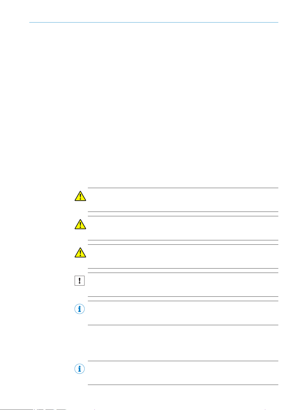
The displacement measurement sensor uses the triangulation principle for distance
measurement. This technology makes it possible to measure the distance between the
displacement measurement sensor and an object.
Figure 1: Triangulation principle
Receiver
1
Lens
2
Object
3
Laser
4
3.2
A point of light is projected onto the measuring object. The light reflected is captured by
a light-sensitive receiver at a specific angle. Based on the angle between the send and
receive direction, the position of the object is triangulated (lat. Triangulum: triangle).
The displacement measurement sensor can be configured via the SOPASair user inter‐
face. For more information visit:
www.sick.com/SOPASair
b
Setup and dimensions
All measurements in mm (inch).
12
O PE R AT I NG IN S TR U CT I ON S | OD5000 8021391//2017-10-06 | SICK
Subject to change without notice
Page 13
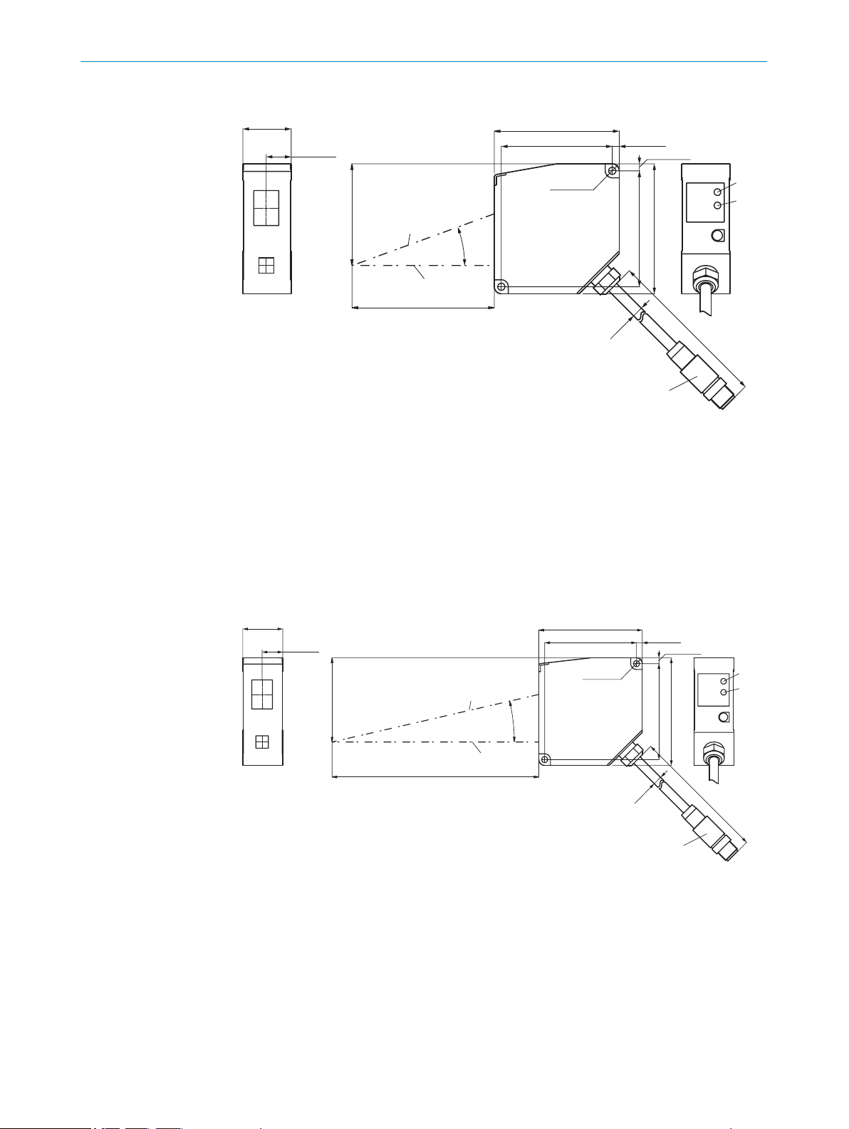
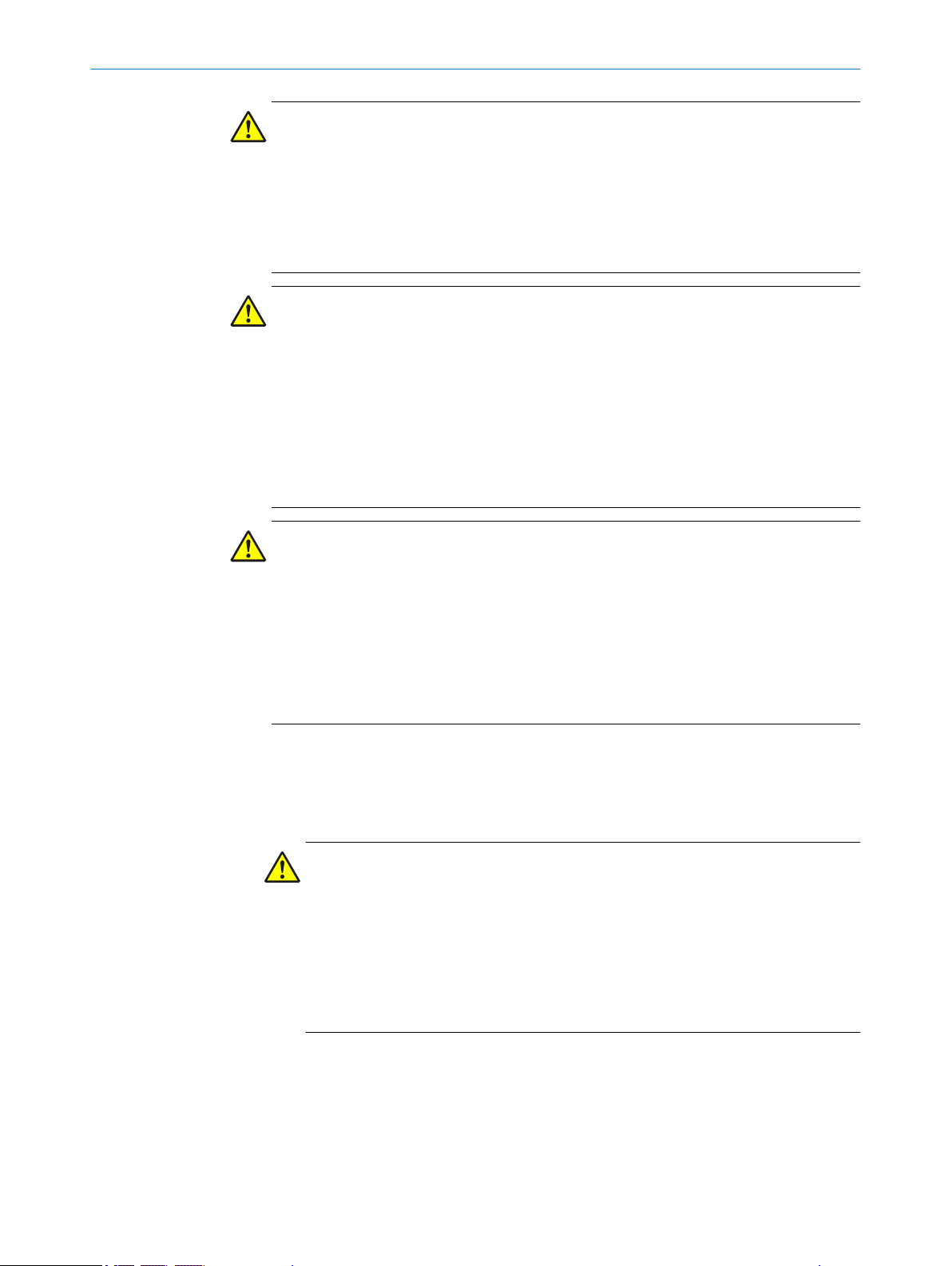
OD5000-C85xxx
20°
85 (3.35) ±20
61
2 - Ø 4.3
(0.17)
Ø
6.5
(0.26)
29
(1.14)
15 (0.59)
75 (2.95)
66.6 (2.62)
4.2 (0.17)
4.2 (0.17)
69.6 (2.74)
78 (3.07)
500
(19.69)
61 (2.40)
2
3
4
5
6
7
1
2 - Ø 4.3
(0.17)
Ø
6.5
(0.26)
29
(1.14)
15 (0.59)
13°
150 (5.91) ±40
75 (2.95)
66.6 (2.62)
4.2 (0.17)
4.2 (0.17)
69.6 (2.74)
78 (3.07)
500
(19.69)
61 (2.40)
2
3
4
5
6
7
1
Figure 2: Setup and dimensions
Reference plane
1
Optical axis, receiver
2
Optical axis, sender
3
Measuring range
4
Link LED
5
Status LED
6
Plug connector, M12, 8-pin
7
PRODUCT DESCRIPTION 3
OD5000-C150xxx
8021391//2017-10-06 | SICK O PE R AT I NG IN S TR U CT I ON S | OD5000
Subject to change without notice
Figure 3: Setup and dimensions
1
2
3
4
5
6
7
Reference plane
Optical axis of the receiver
Optical axis of the sender
Measuring range
Link LED
Status LED
Plug connector, M12, 8-pin
13
Page 14
51,7
39
39
M12
3
2
1
Ø 120 μm
0 65
(2.56)
85
(3.35)
105
(4.13)
Ø 120 μmØ 70 μm
Distance (mm)
Ø 120 μm
0 65 85 105
Ø 120 μmØ 70 μm
Distance (mm)
1500 μm 2500 μm2000 μm
3 PRODUCT DESCRIPTION
Y-distribution
Figure 4: Setup and dimensions
1
2
3
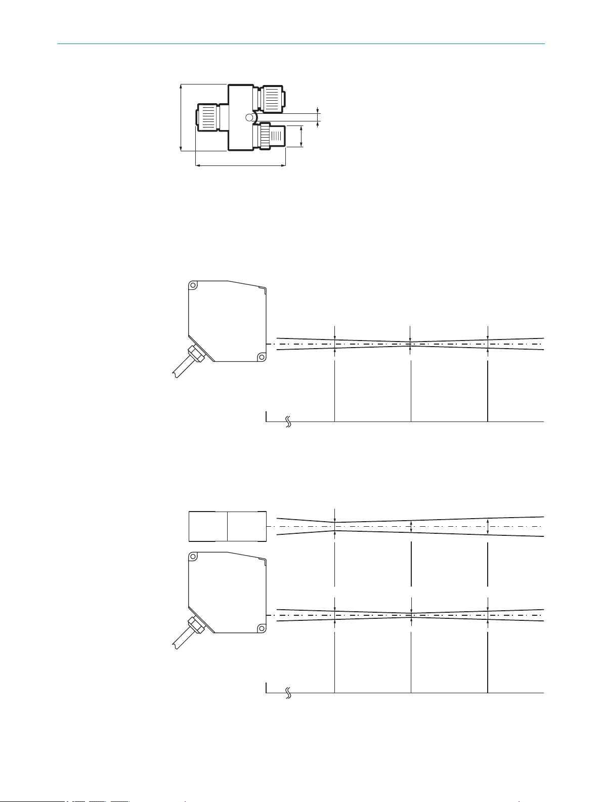
3.2.1 Light spot size
OD5000-C85T20
M12, 4-pin, A-coded
M12, 5-pin, D-coded
M12, 8-pin, A-coded
Figure 5: Typical light spot size of OD5000-C85T20
OD5000-C85W20
Figure 6: Typical light spot size of OD5000-C85W20
14
O PE R AT I NG IN S TR U CT I ON S | OD5000 8021391//2017-10-06 | SICK
Subject to change without notice
Page 15
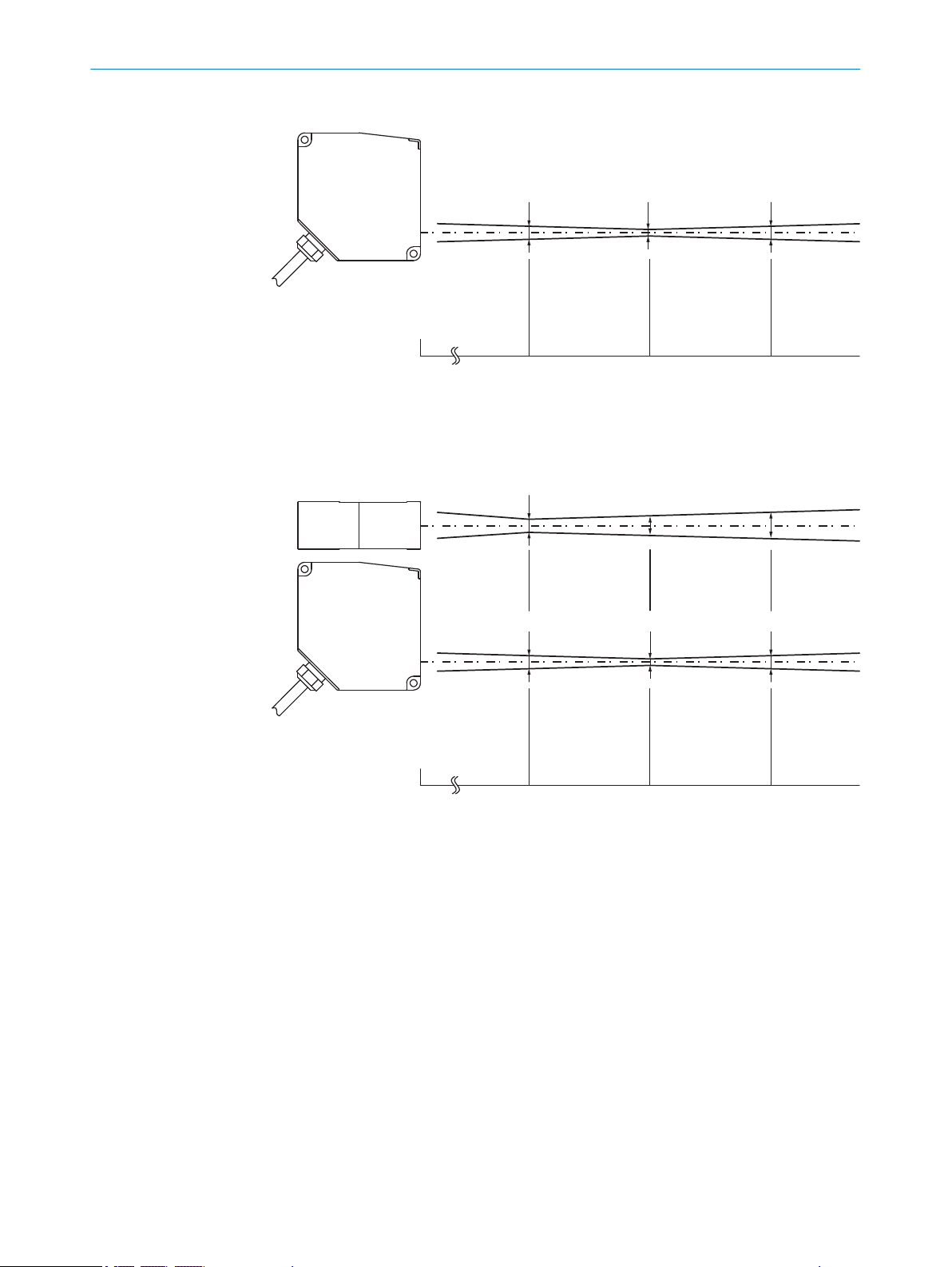
OD5000-C150T40
Ø 120 μmØ 300 μm Ø 300 μm
Distance (mm)
0 110
(4.33)
150
(5.91)
195
(7.68)
Ø 120 μmØ 300 μm Ø 300 μm
Distance (mm)
0 10 150 195
4000 μm2000 μm 6000 μm
Figure 7: Typical light spot size of OD5000-C150T40
OD5000-C150W40
PRODUCT DESCRIPTION 3
Figure 8: Typical light spot size of OD5000-C150W40
3.3 Product identification
Type label
The following information can be read from the type label on the device:
8021391//2017-10-06 | SICK O PE R AT I NG IN S TR U CT I ON S | OD5000
Subject to change without notice
15
Page 16

à
8
7
6
2
1
4
5
3
9
ß
3 PRODUCT DESCRIPTION
Figure 9: OD5000 type label
Type code
1
Part number
2
Serial number
3
MAC address
4
Version number
5
EFUP information for China
6
RCM mark of compliance
7
Place of manufacture
8
EU conformity mark
9
Bar code
ß
US and Canada conformity marks
à
16
O PE R AT I NG IN S TR U CT I ON S | OD5000 8021391//2017-10-06 | SICK
Subject to change without notice
Page 17

4 Transport and storage
4.1 Transport
For your own safety, please read and observe the following notes:
NOTICE
Damage to the product due to improper transport.
■
The device must be packaged for transport with protection against shock and
damp.
■
Recommendation: Use the original packaging as it provides the best protection.
■
Transport should be performed by trained specialist staff only.
■
The utmost care and attention is required at all times during unloading and trans‐
portation on company premises.
■
Note the symbols on the packaging.
■
Do not remove packaging until immediately before you start mounting.
TRANSPORT AND STORAGE 4
4.2
Unpacking
■
Before unpacking, it may be necessary to equalize the temperature to protect the
device from condensation.
■
Handle the device with care and protect it from mechanical damage.
4.3 Transport inspection
Immediately upon receipt in Goods-in, check the delivery for completeness and for any
damage that may have occurred in transit. In the case of transit damage that is visible
externally, proceed as follows:
■
Do not accept the delivery or only do so conditionally.
■
Note the scope of damage on the transport documents or on the transport compa‐
ny's delivery note.
■
File a complaint.
NOTE
Complaints regarding defects should be filed as soon as these are detected. Damage
claims are only valid before the applicable complaint deadlines.
4.4 Storage
Store the device under the following conditions:
■
Recommendation: Use the original packaging.
■
Do not store outdoors.
■
Store in a dry area that is protected from dust.
■
So that any residual damp can evaporate, do not package in airtight containers.
■
Do not expose to any aggressive substances.
■
Protect from sunlight.
■
Avoid mechanical shocks.
■
Storage temperature: see "Technical data", page 72.
■
Relative humidity: see "Technical data", page 72.
■
For storage periods of longer than 3 months, check the general condition of all
components and packaging on a regular basis.
8021391//2017-10-06 | SICK O PE R AT I NG IN S TR U CT I ON S | OD5000
Subject to change without notice
17
Page 18
1 2 3
4 5 6
5 MOUNTING
5 Mounting
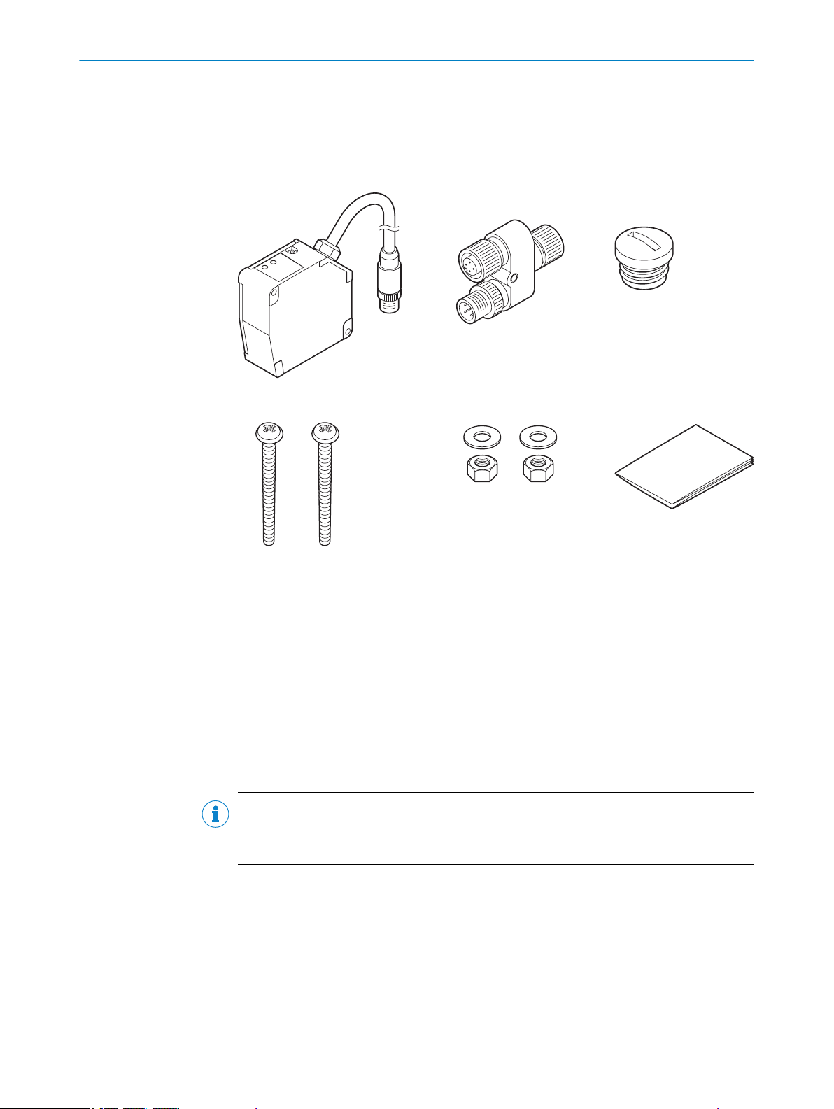
5.1 Scope of delivery
Included with delivery
Figure 10: Scope of delivery
OD5000
1
Y-distribution
2
Protective cap for Y-distribution
3
2 x screws, each M4 x 50 mm
4
2 x M4 nuts and 2 x washers
5
Safety notes
6
Optional: Accessories
Supplied documentation:
■
Safety notes
NOTE
All available documentation can be found online at:
www.sick.com/OD5000
b
18
O PE R AT I NG IN S TR U CT I ON S | OD5000 8021391//2017-10-06 | SICK
Subject to change without notice
Page 19

5.2 Facilities for connecting
1
2
3
4 5
7
8
9
ß6
MOUNTING 5
Figure 11: Facilities for connecting
1
2
3
4
5
6
7
8
9
ß
OD5000
Sensor head extension cable (e.g., DSC-1208-G02MA, part number 6064004)
Y-distribution
Cable with open ends (e.g., DOL-1204-G02MAC, part number 2088079)
Ethernet cable (e.g., SSL-2J04-G02ME, part number 6034414)
M12 AOD1 connection cable, 4-pin on M8, 4-pin (e.g., DSL-2804-G02MC, part num‐
ber 6039180)
AOD1
PC
PLC
Switch
1)
1)
We do not recommend using a standard cable. This connection cable is designed as a twisted pair.
8021391//2017-10-06 | SICK O PE R AT I NG IN S TR U CT I ON S | OD5000
Subject to change without notice
19
Page 20
2x
1
2
5 MOUNTING
5.3 Mounting instructions
Observe the technical data.
•
Protect the sensor from direct sunlight.
•
To prevent condensation, avoid exposing the sensor to rapid changes in tempera‐
•
ture.
The mounting site has to be designed for the weight of the device.
•
To avoid inaccurate measurements when installing multiple devices: Make sure
•
that the laser light spot of one device is not in the visible range of another device.
Take into account the device warm-up time of 10 minutes. During the device
•
warm-up phase, the measured values are subject to an increased variance (tem‐
perature drift).
5.4 Mounting device
1. Mount the displacement measurement sensor using the designated fixing holes,
see "Setup and dimensions", page 12.
2. Make the electrical connection. Attach and tighten a voltage-free cable, see "Con‐
necting the device electrically", page 27.
3. Switch on the supply voltage.
✓
The status LED lights up green.
The device needs around 10 seconds of initialization time before it is ready for
operation.
4. Align the light spot so that the desired object is measured.
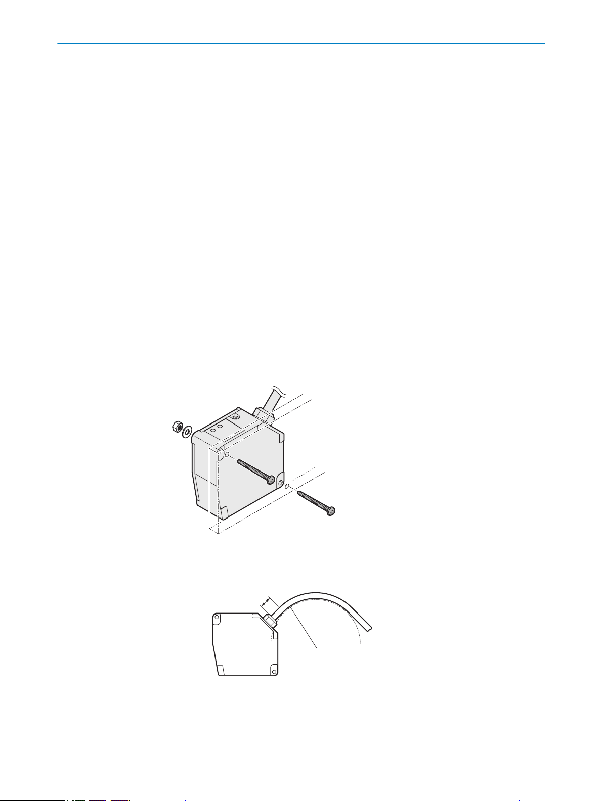
Mounting on the wall
Figure 12: Mounting on the wall
Permissible bend radii of the connection cable
20
Figure 13: Permissible bend radius
At least 10 mm
1
O PE R AT I NG IN S TR U CT I ON S | OD5000 8021391//2017-10-06 | SICK
Radius of at least 60 mm
2
Subject to change without notice
Page 21
1 2
m m X
MOUNTING 5
NOTICE
■
Do not bend the cable less than 10 mm from the sensor head.
■
Do not bend the cable with a radius of more than 60 mm.
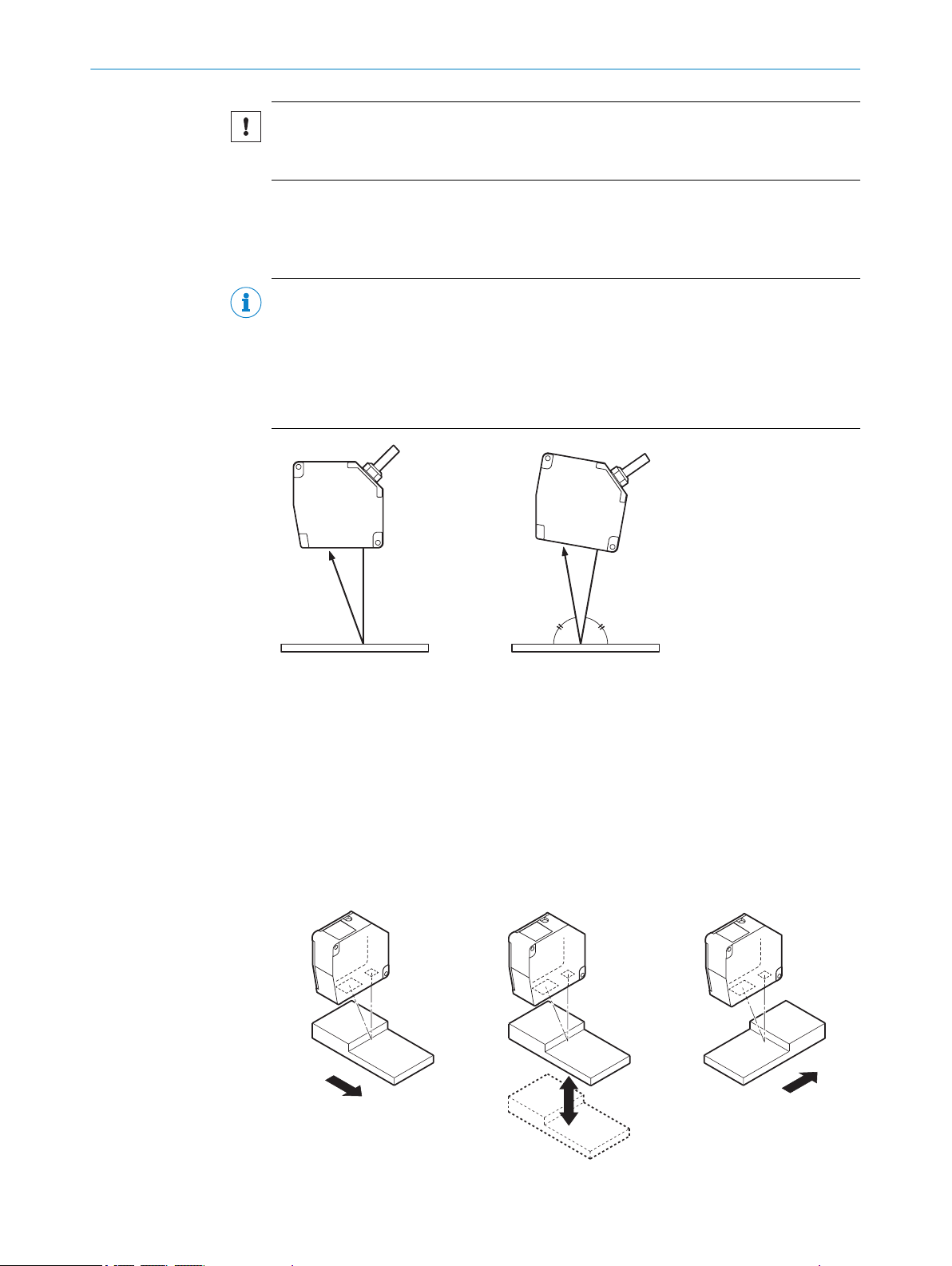
Mounting variations
There are two mounting variations for the device. Typically, diffuse reflection is used.
Specular reflection is used when transparent or reflective surfaces are to be registered.
NOTE
The housing form for the device indicates the orientation of the correct mounting
method. When mounting the device for the measurement of reflective objects, the
device must be mounted so that it is slightly tilted. In doing so, the slanted edge of the
housing must be positioned so that it is perpendicular to the measuring object. In this
mounting variation, only a reduced measuring range is available, see "Technical data",
page 72.
Figure 14: Mounting variations
Diffuse reflection
1
Specular reflection
2
5.4.1 Mounting the device depending on application
With height differences
The preferred direction must be taken into account during mounting in order to prevent
shadows.
Figure 15: Mounting with height differences
8021391//2017-10-06 | SICK O PE R AT I NG IN S TR U CT I ON S | OD5000
Subject to change without notice
21
Page 22

m X
m X
m X
5 MOUNTING
With different material or colors
Figure 16: Mounting with different material or colors
With rotating surfaces
Figure 17: Mounting with rotating surfaces
With holes or recesses
Figure 18: Mounting with holes or recesses
22
O PE R AT I NG IN S TR U CT I ON S | OD5000 8021391//2017-10-06 | SICK
Subject to change without notice
Page 23

Mounting on the wall
m X
Figure 19: Mounting on the wall
MOUNTING 5
8021391//2017-10-06 | SICK O PE R AT I NG IN S TR U CT I ON S | OD5000
Subject to change without notice
23
Page 24

3
2
1
1
4 3
2
6 ELECTRICAL INSTALLATION
6 Electrical installation
6.1 Safety
WARNING
Personal injury due to incorrect supply voltage.
An incorrect supply voltage may result in personal injury.
■
Only operate the device using safety extra-low voltage and safe electrical insula‐
tion as per protection class III.
NOTICE
Equipment damage or unpredictable operation due to working with live parts.
Working with live parts may result in unpredictable operation.
■
Only carry out wiring work when the power is off.
■
Only connect and disconnect electrical connections when the power is off.
6.2 Wiring notes
NOTICE
Faults due to incorrect wiring.
Incorrect wiring may result in operational faults.
■
Follow the wiring notes precisely.
NOTE
Preassembled cables can be found online at:
www.sick.com/OD5000
•
6.3 Pin assignment of the connections
Y-distribution
Figure 20: Y-distribution connections
M12, 4-pin, A-coded
1
M12, 5-pin, D-coded
2
M12, 8-pin, A-coded
3
The Y-distribution is only intended for use as a distributor and not as an amplifier.
Figure 21: Male connector, M12, 4-pin, A-coded
24
O PE R AT I NG IN S TR U CT I ON S | OD5000 8021391//2017-10-06 | SICK
Subject to change without notice
Page 25

1
43
5
2
1
7
2
6
3
4
5
8
ELECTRICAL INSTALLATION 6
Connection 1 to the Y-distribution
Table 2: Pin assignment on 4-pin M12 male connector
Pin Signal Function
1 24 V Voltage supply
2 Input (MF) / RS485+ Input MF (NPN) / Reserved
3 0 V Voltage supply
4 Input (MF) / RS485- Input MF (PNP) / Reserved
- Shield -
Figure 22: Female connector, M12, 5-pin, D-coded
Connection 2 to the Y-distribution
Table 3: Pin assignment on 5-pin M12 female connector
Pin Signal Function
1 TxD+ Network interface
2 RxD+ Network interface
3 TxD- Network interface
4 RxD- Network interface
5 NC Not connected
- Shield -
Figure 23: Female connector, M12, 8-pin, A-coded
Connection 3 to the Y-distribution
Table 4: Pin assignment on 8-pin M12 female connector
Pin Signal Function
1 Input (MF) / RS485+ Input MF (NPN) / Reserved
2 0 V Voltage supply
3 24 V Voltage supply
4 TxD- Network interface
5 RxD+ Network interface
6 TxD+ Network interface
7 Input (MF) / RS485- Input MF (PNP) / Reserved
8 RxD- Network interface
- Shield -
8021391//2017-10-06 | SICK O PE R AT I NG IN S TR U CT I ON S | OD5000
Subject to change without notice
25
Page 26

1
4 3
2
1
43
2
6 ELECTRICAL INSTALLATION
Pin assignment of the connections for M12 converter, RJ45
Figure 24: Male connector, M12, 4-pin, D-coded
Table 5: Pin assignment on 4-pin M12 male connector
Pin Signal Function
1 TxD+ Network interface
2 RxD+ Network interface
3 TxD- Network interface
4 RxD- Network interface
- Shield -
Pin assignment for M12 voltage supply, 4-pin (based on DOL-1204-G02MAC, part num‐
ber 2088079, can be used for OD5000 standalone operation)
Figure 25: Male connector, RJ45
Table 6: Pin assignment on male connector, RJ45
Pin Signal Function
1 TxD+ Network interface
2 TxD- Network interface
3 RxD+ Network interface
4 NC Not connected
5 NC Not connected
6 RxD- Network interface
7 NC Not connected
8 NC Not connected
- Shield -
Figure 26: Male connector, M12, 4-pin, A-coded
Table 7: Pin assignment on 4-pin M12 female connector
Pin Signal Function
1 24 V Voltage supply
2 Input (MF) / RS485+ Input MF (NPN) / Reserved
3 0 V Voltage supply
4 Input (MF) / RS485- Input MF (PNP) / Reserved
- Shield -
26
O PE R AT I NG IN S TR U CT I ON S | OD5000 8021391//2017-10-06 | SICK
Subject to change without notice
Page 27

6.4 Connecting the device electrically
NOTE
The connection diagram, and information on inputs and outputs, can be found on the
side plate on the device.
NOTICE
All electrical circuits must be connected to the device with safety extra-low voltage
(SELV or PELV).
1. Ensure that the voltage supply is not connected.
2. Observe the wiring instructions, see "Wiring notes", page 24.
3. Connect the device according to the connection diagram.
ELECTRICAL INSTALLATION 6
8021391//2017-10-06 | SICK O PE R AT I NG IN S TR U CT I ON S | OD5000
Subject to change without notice
27
Page 28

12 3
7 OPERATION
7 Operation
7.1 General notes
If the device is not able to perform a measurement even though the measuring object is
within the specified measuring range, the alignment should be checked and optimized
if necessary see "Mounting the device depending on application", page 21. In general,
adjusting the measuring rate can increase the measuring ability for very dark objects,
for example.
To prevent EMC interference, please observe the wiring instructions.
7.2 Control elements and status indicators
7.2.1 Indicator lights
Figure 27: OD5000 control panel
Communication LED (link)
1
Status LED (power)
2
Cover screw for reset pushbutton
3
Table 8: Meaning of the indicator lights
Indicator Status Color State
Communication LED (link)
Status LED (power)
Ö
Flashing
O
Permanently on
Ö
Ö
Ö
O
O
O
Ö
Green Ethernet communication is
active
Blue Laser off
Red Invalid measurement
Red Measured value is in the
positive value range
Orange Measured value is in the
negative value range
Green All active outputs have a
high signal / no output
active
White “Find me” is active
28
O PE R AT I NG IN S TR U CT I ON S | OD5000 8021391//2017-10-06 | SICK
Subject to change without notice
Page 29

7.2.2 Operating elements
Table 9: Functions of the reset pushbutton
Hold down pushbut‐
ton for
< 1 s None Unchanged Changes are not
1 to 5 s IP address is initial‐
5 to 10 s IP address is changed
> 10 sec All settings are initial‐
NOTE
■
The reset pushbutton is only accessible once the screw has been removed.
■
■
■
Function LED status Description
adopted if pushbutton
is not pressed for long
enough
ized (static IP)
(DHCP)
ized
Flashing orange
(slowly)
Flashing green (slowly) IP address is obtained
Flashing green
(quickly)
IP address is changed
to 192.168.0.01
and set to DHCP
All settings are reset
to the factory settings
Press reset pushbutton to reset all settings to factory settings.
Always remove and store the screw together with the sealing ring.
Refit the screw and sealing ring.
Observe the maximum torque of 0.08 Nm ±20%.
OPERATION 7
The IP67 enclosure rating is only ensured with a proper screw connection and intact
sealing ring.
7.3
Operation via web browser (SOPASair)
7.3.1 Determining the device IP address
DHCP is preset on the device as standard meaning that the IP address is obtained
automatically.
In order to ascertain the IP address assigned to the device, please contact the relevant
network administrator or use SOPAS ET.
The device IP address can also be verified and adjusted by a device-specific search in
SOPAS ET.
The most up-to-date version of the software is available at:
www.sick.com/OD5000
b
7.3.2 Connecting via the web browser
The following browsers are supported:
Internet Explorer (version 11 or higher)
•
Google Chrome (version 49 or higher)
•
1. Start browser.
2. Enter the device IP address.
✓
The SOPASair settings screen is displayed.
8021391//2017-10-06 | SICK O PE R AT I NG IN S TR U CT I ON S | OD5000
Subject to change without notice
29
Page 30

OPERATION
7
Logging in
Figure 28: Log-in screen
The Maintenance and Expert user levels are available for choosing settings.
Maintenance user name: Maintenance
Maintenance password: main
The Expert user level is for the exclusive use of trained and authorized service personnel
at SICK AG, see "Expert", page 53.
NOTE
After logging in, the "pencil" button may need to be clicked to allow editing.
7.3.3 Overview of SOPASair
Figure 29: Overview of SOPASair
The following menu items are available when viewed online:
Monitoring
•
Measurement
•
I/O channels
•
Device
•
Communication
•
Recording
•
Info
•
Expert
•
30
O PE R AT I NG IN S TR U CT I ON S | OD5000 8021391//2017-10-06 | SICK
Subject to change without notice
Page 31
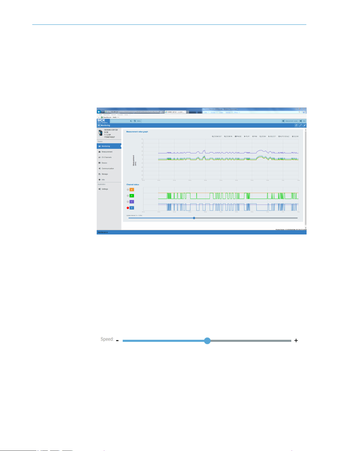
7.3.4 Monitoring
OPERATION 7
The left-hand navigation screen can be viewed as standard but can be hidden by click‐
ing on the upper right-hand buttons with three bars.
Two buttons can be seen on each bar at the top:
Measured values: Displays the current measured values. The display of the measured
value can be adapted using two buttons.
Help: Displays help texts on the current settings.
7.3.5 Measurement
Figure 30: Overview of the Monitoring tab
The measured value plotter displays the current measured values (distance/thickness).
Current measured values can be hidden or displayed at any time using the Measured val‐
ues button in the bar at the top of the screen. The color corresponds to the respective
channel.
The display of the individual channels can be activated and deactivated using buttons A
to D.
The digital plotter displays the statuses of the output signals for channels A to D.
The status of the outputs is displayed by LEDs to the left of the buttons:
Red = output active
•
Grey = output inactive
•
The speed at which the measured values and the digital plotter are output is adjusted
equally by sliding the controller on the speed bar.
Measurement settings can be made in the Measurement tab.
8021391//2017-10-06 | SICK O PE R AT I NG IN S TR U CT I ON S | OD5000
Subject to change without notice
31
Page 32

7 OPERATION
Figure 31: Overview of the Measurement tab
7.3.5.1 Setting diffuse or specular reflection
One of two options can be selected depending on the measuring object and the mount‐
ing method, see "Mounting device", page 20.
NOTE
Some device variants only support one mode.
The OD5000-C150xxx only supports diffuse reflection.
Part number Device Diffuse Specular
6063623 OD5000-C85T20 x x
6063624 OD5000-C85W20 x x
6063625 OD5000-C150T40 x Not supported
6063626 OD5000-C150TW0 x Not supported
NOTE
The measuring range is reduced if the OD5000-C85xxx is reflected specularly, see
"Technical data", page 72.
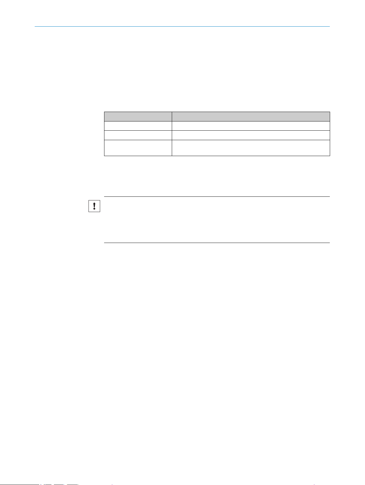
7.3.5.2 Determining the measurement type
This function determines which measurement is used via the respective channel.
Table 10: Adjustments for the measurement type
Setting Meaning
Distance Measures the distance between the zero point and a defined peak
Thickness Measures the distance between two peaks, e.g., a transparent
(object surface)
object with several reflective surfaces (e.g., layers of glass)
32
Depending on the selected measurement type, it is possible to determine on which
peak or between which peaks the measurement is to be taken.
With the distance measurement type, up to eight peaks can be selected. Peak 1 (P1) is
activated by default.
O PE R AT I NG IN S TR U CT I ON S | OD5000 8021391//2017-10-06 | SICK
Subject to change without notice
Page 33

With the thickness measurement type (for measuring a transparent object), a selection
must also be made of the peaks between which the measurement is to be taken. If the
selected peak does not exist then a measurement is not taken. If the same peak is
selected twice in this case, 0 is output as the measured value.
NOTE
The thickness may only be measured with specular reflection mounting. This mode is not
available for all devices in the OD5000 series, see "Setting diffuse or specular reflec‐
tion", page 32.
7.3.5.3 Teaching in the zero point
The current distance is taught in as a new zero point (reference point) or reset to the
output value.
7.3.5.4 Setting the sampling duration
The following settings are possible:
12.5 μs
•
25 μs
•
50 μs (default value)
•
100 μs
•
500 μs
•
1,000 μs
•
AUTO (selects the sampling rate for the quickest possible measurement depending
•
on the measuring object)
OPERATION 7
NOTE
If the sampling duration is set to the shortest time of 12.5 μs then the measuring range
is reduced.
■
Select the required range (near, medium, far) via the configuration interface.
For a sampling duration of 12.5 μs
Table 11: Measuring range for a sampling duration of 12.5 μs
OD5000C85W20
Near 65.0 mm to 77.7 mm
71.5 mm to 74.3 mm (for spec‐
ular reflection)
Medium (starting value) 73.5 mm to 90.8 mm
70.6 mm to 86.9 mm (for spec‐
ular reflection)
Far 84.8 mm to 105.0 mm
81.0 mm to 91.5 mm (for spec‐
ular reflection)
OD5000C85T20
OD5000C150W40
110.0 mm to 134.4 mm
124.8 mm to 166.3 mm
150.2 mm to 190.0 mm
OD5000C150T40
An upper and lower limit must be set for the auto setting. The actual sampling duration
is automatically adjusted within these limits.
Table 12: Adjustments for the upper and lower limit
Lower limit Upper limit
25 μs (default value) 25 μs
50 μs 50 μs
100 μs 100 μs
8021391//2017-10-06 | SICK O PE R AT I NG IN S TR U CT I ON S | OD5000
Subject to change without notice
33
Page 34

1 2
3
4
5
0 mm 0 mm
7 OPERATION
Lower limit Upper limit
200 μs 200 μs
500 μs 500 μs (default value)
1,000 μs 1,000 μs
7.3.5.5 Synchronizing several OD5000 sensors
If several sensor heads are used in the application, they may be synchronized using the
following settings. One sensor head is selected by default. To use two sensor heads, a
drop-down menu is displayed with the following request:
Table 13: Adjustments for synchronization mode
Setting Meaning
Synchronous Synchronizes several sensor heads
Anti interference 1/2 Switches between two sensor heads
The following should be considered when using these modes:
In synchronization mode, the measurement results from two sensor heads are recorded
simultaneously. An application possibility is measuring the thickness of non-transpar‐
ent objects using two sensor heads, for example. The individual results from the sensor
heads must be accounted for using special control software, which is not possible with
the SOPASair configuration software.
In Anti interference mode, the measurement results from several sensor heads are
recorded one after the other. This increases the measurement time to double the sam‐
pling duration for that measurement. This can be in used, for example, in an application
in which the laser beams overlap a pair of sensor heads.
To use this mode, the following settings must be made:
1. Define one device as a master and the others as slaves, see "Network settings",
page 49.
2. Set Anti interference 1 for the master.
3. Set Anti interference 2 for the slave.
✓
The devices will now take measurements one after the other.
7.3.5.6 Determining the direction of detection
The direction of detection determines whether the measured value increases (posi‐
tive) or decreases (negative) when the distance between the device and measuring
object increases.
34
O PE R AT I NG IN S TR U CT I ON S | OD5000 8021391//2017-10-06 | SICK
Figure 32: Direction of detection
Set to positive
1
Set to negative
2
Sensor
3
Center point of the measurement
4
Subject to change without notice
Page 35

Measuring object
Peak 4
Peak 3
Peak 2
Peak 1
1
2
3
4
1
2
3
45
6
5
To determine the order of the peaks, see "Checking the light distribution curve and
peaks", page 35.
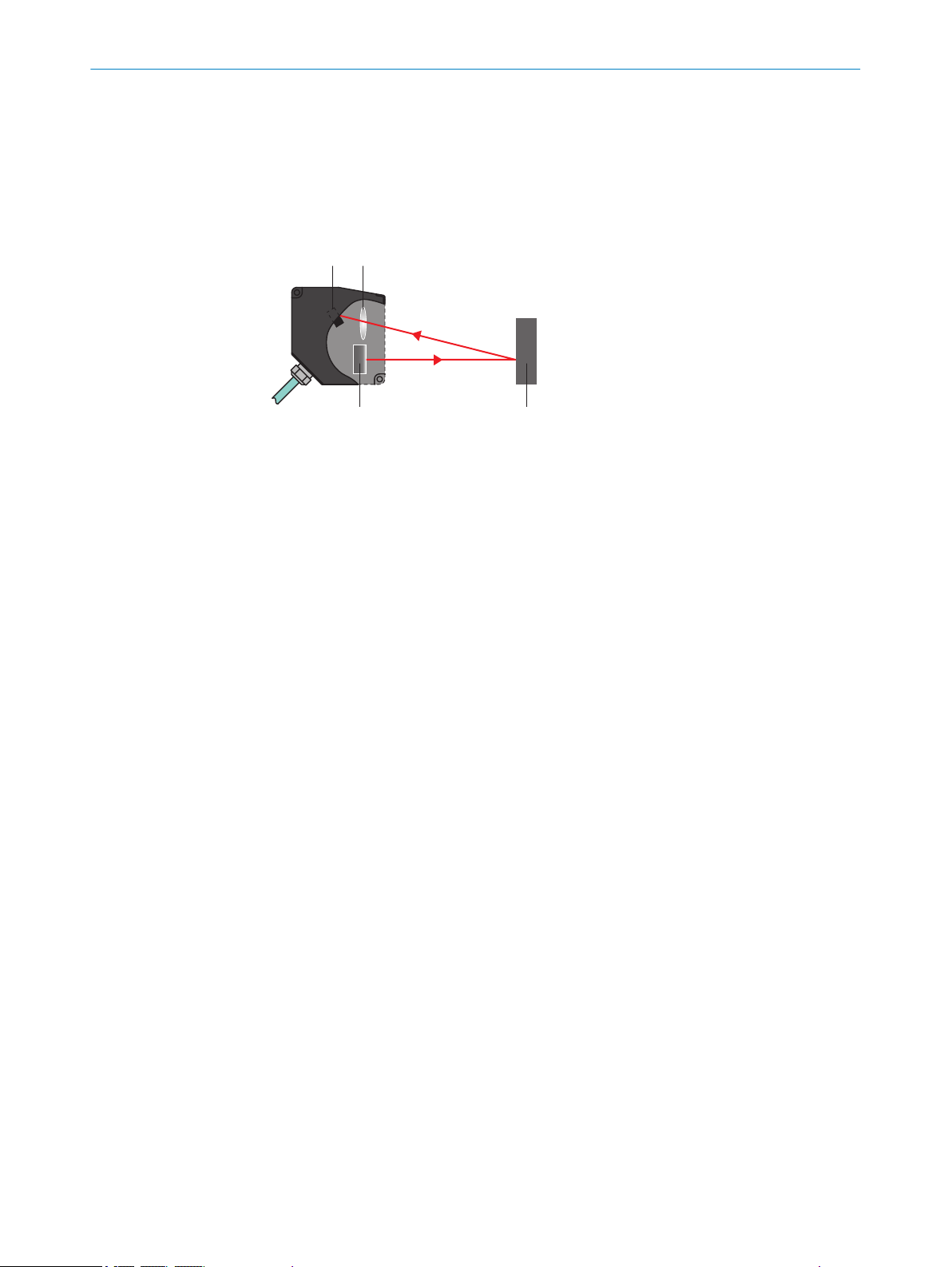
7.3.5.7 Checking the light distribution curve and peaks
In this settings display, the user can check the light waveform which is displayed on the
receiver. The peak displays the distance to the measuring object. If the device detects
peaks then these are displayed in the corresponding light waveform and labeled P1 to
P8.
OPERATION
7
Figure 33: Light distribution curve
Sensor
1
Laser
2
Reflective surface
3
Side close to the sensor head (depending on the Measuring direction setting)
4
Side far from the sensor head (depending on the Measuring direction setting)
5
Reflected light intensity
6
During the measurement, light can be reflected from several surfaces at the same
time; for example, from the front and rear of a transparent measuring object.
Direction of detection: The device assigns numbers to the scanned surfaces. This
means that the measurement can focus on individual reflection points (peaks). The
numbers are assigned (using the direction of detection: near/far) in such a way that
they either increase (near) or decrease (far) beginning on the side closest to the sensor.
Example based on four glass panes:
8021391//2017-10-06 | SICK O PE R AT I NG IN S TR U CT I ON S | OD5000
Subject to change without notice
35
Page 36

1 ( 8) *
2 ( 7)
3 ( 6)
4 ( 5)
7 ( 2)
8 ( 1)
5 ( 4)
6 ( 3)
1
7 OPERATION
Figure 34: Peak detection
Laser
1
1 = Near
(8) = Far
Near is selected as the standard setting, i.e., the numbering increases from the side
closest to the sensor.
7.3.6 Settings for channels A–D
Figure 35: Overview of the settings tab for channels A–D
7.3.6.1 Setting the measurement value filter
36
The measurement value filters optimize the signal diagram in order to simplify the eval‐
uation by the control system (e.g., for regulation tasks). You can select from the follow‐
ing filters:
Mean filter
O PE R AT I NG IN S TR U CT I ON S | OD5000 8021391//2017-10-06 | SICK
•
Median filter
•
By default, the mean filter is set to a filter depth of 256 measured values and the
median filter to a filter depth of 31 measured values.
Subject to change without notice
Page 37

Ausgangssignal
Zeit t
1
2
4
3
4
3
21
OPERATION 7
Mean filter
The mean filter carries out a moving averaging of the measured values. This filter is
suitable for smoothing a noisy signal diagram in order to ensure better repeatability.
Filter depth: 1 / 2 / 4 / 8 / 16 / 32 / 64 / 128 / 256 (default value) / 512 / 1024 /
2048 / 4096 / 8192 / 16384 / 32768 / 65536 (unit: measuring point)
The mean filter can be deactivated by selecting filter depth 1.
Median filter
The moving median filter sorts the measured values according to their size and selects
the middle value from a sequence. This filter is suitable for excluding individual outliers
from the calculation of an average value.
Filter depth: Off / 7 / 15 / 31 (default value)
Both types of filter affect the response time of the device.
Figure 36: Median filter
1
2
3
4
True distance
Measured value with median
Measured value with averaging
Measured value without averaging
8021391//2017-10-06 | SICK O PE R AT I NG IN S TR U CT I ON S | OD5000
Subject to change without notice
37
Page 38

ON
OFF
1
2
ON
OFF
1
2
3
4
5
7 OPERATION
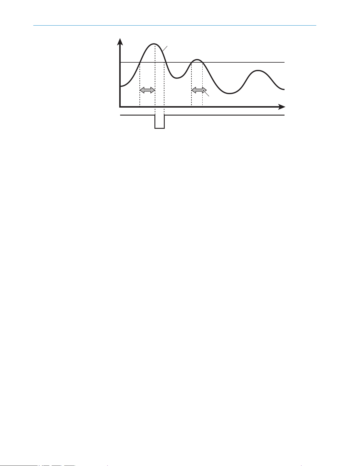
7.3.6.2 Setting the Hold function
The Hold function extracts a specific value such as the maximum or minimum value
within a detection period. The value which was set under Hold Set is used as the holding
period.
Use this function after entering Hold Reset if Auto Peak or Auto Bottom is used.
•
Off
When the hold function is deactivated, the measurement result is output in an unedited
format and the Hold Input is ignored.
Figure 37: Hold function off
Measured value
1
Hold function
2
Peak
The highest value within the detection period is output.
Figure 38: Hold function peak
Measured value
1
Hold
2
Detection period
3
Internal measured value
4
Measured value for the hold function peak
5
38
Bottom
The lowest value within the detection period is output.
O PE R AT I NG IN S TR U CT I ON S | OD5000 8021391//2017-10-06 | SICK
Subject to change without notice
Page 39

ON
OFF
1
2
3
4
5
Figure 39: Bottom hold function
ON
OFF
1
2
3
4
Measured value
1
Hold function
2
Detection period
3
Internal measured value
4
Measured value of the Bottom hold function
5
Sample Hold
OPERATION 7
The value detected within the detection period is output.
Figure 40: Sample Hold hold function
Measured value
1
Hold function
2
Internal measured value
3
Measured value of the Sample Hold hold function
4
Auto Peak
The highest value is recorded as soon as Hold Reset Input is detected.
8021391//2017-10-06 | SICK O PE R AT I NG IN S TR U CT I ON S | OD5000
Subject to change without notice
39
Page 40

ON
OFF
1
2
3
4
ON
OFF
1
2
3
4
P(2)
P(1)
B(1)
B(2)
P(1)-B(1)
P(2)-B(2)
ON
OFF
1
3
5
3
4
2
7 OPERATION
Figure 41: Auto Peak hold function
Measured value
1
Hold function
2
Internal measured value
3
Measured value of the Auto Peak hold function
4
Auto Bottom
The lowest value is recorded as soon as Hold Reset Input is detected.
Figure 42: Auto Bottom hold function
Measured value
1
Hold function
2
Measured value of the Auto Bottom hold function
3
Internal measured value
4
Peak to Peak
The value is maintained from peak to peak.
Figure 43: Peak to Peak hold function
1
Measured value
40
O PE R AT I NG IN S TR U CT I ON S | OD5000 8021391//2017-10-06 | SICK
Subject to change without notice
Page 41
Hold function
2
Duration of measurement
3
Internal measured value
4
Output hold value
5
7.3.6.3 Setting the alarm (action in case of incorrect measurements)
This function allows you to determine the output when a measurement is not possible.
Table 14: Settings for action in case of incorrect measurements
Setting Meaning
User-defined value A defined value is displayed
Hold last value The most recently measured value is displayed
User-defined value at a set
time
Forces the output of a user-defined value at a set time during an
incorrect measurement
Action in case of incorrect measurements: User-defined value
The user-defined value is set in the section on Action in case of incorrect measurements.
Values ±2,147,483 mm are possible; the default value is 1.00 mm.
OPERATION 7
NOTICE
If the AOD1 setting is selected for Input terminal under Communication, the user-defined
value is automatically adjusted to the following value:
209.7152 mm
This value must not be modified.
Error suppression time
When User-defined value at a set time is selected, then the number of measuring points is
determined under Error suppression time, during which the most recently measured value
is displayed. If a measurement still cannot be taken after this period then the userdefined value is displayed.
Values are possible from 0 (default value) to 4,095.
Restoration period following an error
When User-defined value at a set time is selected, then the number of measuring points is
determined under Restoration period following an error. The user-defined value is continued
to be output although a measurement is possible again.
Values are possible from 0 (default value) to 4,095.
8021391//2017-10-06 | SICK O PE R AT I NG IN S TR U CT I ON S | OD5000
Subject to change without notice
41
Page 42

7 OPERATION
7.3.7 I/O channels
Figure 44: Overview of the I/O channels tab
In this view, the settings are made for the digital signal of each channel. Four channels
are available for this. Settings can be made for each channel individually.
An MF input is also available. The settings for this option can also be made under I/O
channels.
NOTE
The digital signals cannot be measured on the device pins but are made available via
the Ethernet interface as part of data transmission.
7.3.7.1 Setting limits
The threshold is set using limits. In doing so, the digital signal is set to ON or OFF.
Values ±2,000.00 mm are permissible for the upper limit; the default value is
+2.0 mm (for the 85 mm variant) or +4.0 mm (for the 150 mm variant).
Values ±2,000.00 mm are permissible for the lower limit; the default value is
-2.0 mm (for the 85 mm variant) or -4.0 mm (for the 150 mm variant).
7.3.7.2 Setting the hysteresis
If the measured value rises slightly above or drops slightly below the threshold, this can
lead to the input and output repeatedly switching on and off within a short space of
time. This can be prevented by assigning a defined tolerance to the measured value via
the hysteresis setting, beyond which the device switches.
42
NOTE
The limits and the hysteresis can also be set by moving the corresponding marker in the
graphic (blue: limits, yellow: hysteresis).
Values of ±2,000.000 mm are possible; the default value is 0.0000 mm.
O PE R AT I NG IN S TR U CT I ON S | OD5000 8021391//2017-10-06 | SICK
Subject to change without notice
Page 43

Hysteresis
Upper
limit
ON
OFF
Figure 45: Hysteresis
1
2
34
Upper
limit
ON
OFF
7.3.7.3 Setting the switch-on delay (On Delay)
This setting is used to delay the switching on of the output by a set amount of time if
the measured value exceeds the threshold.
This setting prevents the input and output from repeatedly switching on and off within a
short period of time and enables the use of a slower PLC.
OPERATION 7
The delay is increased by the configured time by switching the switching output to ON.
Figure 46: On Delay
Measured value
1
Shorter than the defined time period
2
The measured value is of equal size or greater than the threshold
3
Output switches to OFF
The measured value is below the threshold
4
Output switches to ON
Values are possible from 0 ms (default value) to 100 ms.
7.3.7.4 Setting the switch-off delay (Off Delay)
This setting is used to delay the switching off of the output by a set amount of time if
the measured value falls below the threshold.
This function suppresses short signals (bursts) which prevents inaccurate measure‐
ments.
8021391//2017-10-06 | SICK O PE R AT I NG IN S TR U CT I ON S | OD5000
Subject to change without notice
43
Page 44
1
2
34
Upper
limit
ON
OFF
OPERATION
7
Figure 47: Off Delay
Measured value
1
Shorter than the defined time period
2
Output switches to OFF
3
Output switches to ON
4
Values are possible from 0 ms (default value) to 4,000 ms.
7.3.7.5 Setting the calibration
The display for setting the calibration will vary depending on the settings in the Measure‐
ment tab.
Distance
Shift
This setting is used to move the measured value to a fixed value. A corresponding cor‐
rection value (shift) is added to or subtracted from the measured value of the sensor
head.
Span
This value is selected according to the ratio of the measurement error to the measuring
range. It is used for:
compensating for a deviation caused by a tilted installation (distance)
•
measuring the thickness of glass (so that refraction may be taken into account)
•
In a distance measurement, both values must usually be adjusted. With the thickness
measurement type (for measuring the thickness of glass), it is important to set the cali‐
bration factor (span) to the correct value to ensure a precise measurement and to com‐
pensate for the refraction index of the measured material. Only the span value can be
set for the thickness measurement.
Teaching-in is a recommended process. For the distance measurement, two different
objects which are far apart must be placed in front of the sensor – the distances (refer‐
ence values) must be known.
Teaching-in the distance measurement
44
O PE R AT I NG IN S TR U CT I ON S | OD5000 8021391//2017-10-06 | SICK
Subject to change without notice
Page 45

OPERATION 7
1. Position the first object.
2. Enter the reference value for the first object in Target value 1.
3. Click on the Teach-in point 1 button.
4. Position the second object.
5. Enter the reference value for the second object in Target value 2.
6. Click on the Teach-in point 2 button.
✓
The sensor calculates the suitable shift and span values and applies these to the
measurement.
Teaching-in for thickness measurement
1. Position object with a known reference thickness in front of the sensor.
2. Enter the reference thickness in the Reference thickness field.
3. Click on the Teach-in button.
✓
NOTE
The span and shift values can be adjusted manually at any time after the teach-in.
7.3.7.6 Setting One shot
If this function is activated, the output is only given once when the conditions for output
are met. The output is then switched off.
The sensor calculates the suitable span value and applies this to the measure‐
ment.
The output time is set via Off Delay.
8021391//2017-10-06 | SICK O PE R AT I NG IN S TR U CT I ON S | OD5000
Subject to change without notice
45
Page 46

7 OPERATION
7.3.8 I/O settings input (MF)
Figure 48: Tab showing the overview of the I/O settings of input (MF)
7.3.8.1 Setting the polarity
This is where the polarity is set for the external input terminal.
Table 15: Input terminal settings
Setting Meaning
High Switches on when input is detected
Low Switches off when input is detected
High (N.O.) is set by default.
7.3.8.2 Setting the switching function
This is where the function is set for the external input terminal.
Table 16: Switching function settings
Setting Meaning
None Input (MF) is not used (input is ignored)
Laser off Laser is switched off during input
Hold function ON/reset Used as hold input/reset input when the hold function is activated
Start process recording Used as a recording input
Measured value offset Used as an Offset or as an Offset Release Input
For Peak Hold/Bottom Sample Hold: Hold input
For Auto Peak Hold/Auto Bottom Hold: Reset input
Recording is carried out when activated. When the specified
amount of saved entries is reached, the recording is stopped and
a file is created.
If the input setting is set to OFF during the recording, the process
is paused and a file is created using the data saved up until that
point.
Less than 1 s: Offset
1 s or more: Offset compensation
46
The default mode is None.
O PE R AT I NG IN S TR U CT I ON S | OD5000 8021391//2017-10-06 | SICK
Subject to change without notice
Page 47

7.3.8.3 Setting the debounce
Sets the delay time with which the external input is switched on until actual operation
begins. This prevents the external input from suddenly being switched on or off.
Values are possible from 0 ms to 32,767 ms, the standard value is 20,000 ms.
7.3.9 Device
OPERATION 7
Figure 49: Overview of the Device tab
General device settings can be made in this view. The following functions are available
here:
7.3.9.1 Deactivating the measurement laser
Checking or unchecking the box next to Deactivate measurement laser activates and deacti‐
vates the laser. If the laser is deactivated then measurement stops as a result. The
laser is activated as standard.
7.3.9.2 Resetting the device to factory settings
Selecting this function resets all device settings to their factory settings. This does not
include network settings (e.g., IP addresses). A subsequent device restart (power reset)
is recommended.
7.3.9.3 Setting the sensor time
This section displays the current time as well as the time at which the device was
started. Clicking on the Set current time button adjusts the device time to the time set on
the computer being used.
7.3.9.4 Device identification
When this function is selected, the status LED of the device in question flashes for 5 s.
7.3.9.5 Saving the configuration
When this function is selected, the entire device configuration is saved in a file and pre‐
pared for download. A save location must be selected for the file.
8021391//2017-10-06 | SICK O PE R AT I NG IN S TR U CT I ON S | OD5000
Subject to change without notice
47
Page 48

7 OPERATION
NOTE
The default save location is normally the download folder (this depends on the individ‐
ual browser settings).
7.3.9.6 Loading the configuration
When this function is activated, a previously stored OD5000 configuration file must be
selected from the computer being used. This is then uploaded to the device and all set‐
tings are adopted accordingly.
7.3.10 Communication
Figure 50: Overview of the Communication tab
Settings which affect communication received from or sent to the device can be made
in this view. The following settings are available here:
7.3.10.1 Communication settings
Input settings
This is where the MF access is assigned a function.
The possible selection includes:
External Input: The MF access is used for the selected switching function, see "Set‐
•
ting the switching function", page 46.
AOD1: The OD5000 can be connected with an AOD1 evaluation unit via its pins
•
RS485+/RS485- (see "Pin assignment of the connections", page 24).
NOTE
Only one channel (A) can be used when AOD1 is selected.
AOD1 Baud rate
This is where the speed of communication with the AOD1 is set. The device automati‐
cally establishes a connection with the AOD1 by default and the settings are defined
autonomously.
48
O PE R AT I NG IN S TR U CT I ON S | OD5000 8021391//2017-10-06 | SICK
Subject to change without notice
Page 49

If the settings are not automatically defined then the same speed must be set as is set
for the AOD1. The following values are possible:
•
•
•
•
•
•
•
•
•
•
•
•
•
7.3.10.2 Network settings
Ethernet settings are also defined from the Communication tab.
MAC address
OPERATION 7
9.6
19.2
38.2
57.6
115.2
230.4
312.4
468.8
500.0
625.0
833.3
937.5
1,250 (default value)
The device-specific MAC address is displayed in this field.
IP address
The device IP address is defined in this field.
The default value is 192.168.0.01.
Addressing mode
The user can choose between a static IP address and DHCP (default value) in this field.
Subnet mask
The device subnet mask is defined in this field.
The default value is 255.255.255.0.
Standard gateway
The standard gateway of the device is defined in this field.
The default value is 0.0.0.0.
Accurate time synchronization
A device of the OD series is defined as a time server in this field. This allows the inter‐
nal clock within all the connected sensors to be synchronized precisely via the standar‐
dized precision time protocol (PTP). In this function, a device of the OD series must be
defined as a master; all additional sensors must be defined as a slave.
This procedure is necessary when Synchronous or Anti interference is set as the synchroni‐
zation mode.
Table 17: Accurate time synchronization modes
Mode Meaning
Off (default value) Function has been deactivated
Master Device is defined as master
Slave Device is defined as slave
8021391//2017-10-06 | SICK O PE R AT I NG IN S TR U CT I ON S | OD5000
Subject to change without notice
49
Page 50

7 OPERATION
7.3.11 Recording
NOTE
If a device on the network is already defined as a PTP time server then this must be
used and all OD devices must be defined as slaves. Otherwise, synchronization cannot
be executed properly.
Figure 51: Overview of the Recording tab
Recording is used to prepare measurement data for storage. Output is in the form of a
*.csv file. Saved data is listed and can be downloaded to the corresponding list entry at
the click of a button. The exact download process depends on the individual browser
settings.
Various functions are available via this display.
7.3.11.1 Formatting settings
In the Decimal separator field, the user can select whether the measured values in the
*.csv file use a period or a comma as a decimal separator.
In the Column delimiter field, the user can select whether the data columns in the *.csv
file are separated by a comma or semicolon.
NOTE
*.csv files become illegible if a comma is used as both a decimal separator and column
delimiter.
7.3.11.2 Starting and testing the recording
Start recording
Clicking on the Start recording button starts the recording of the measurement data.
50
Test recording
Clicking on the Test run button starts a single recording. A previously set number of data
entries are collected before data recording stops. Using this function, current measure‐
ment data can be collected and stored flexibly.
O PE R AT I NG IN S TR U CT I ON S | OD5000 8021391//2017-10-06 | SICK
Subject to change without notice
Page 51

7.3.11.3 Determining the allocation
In the Allocation field, the user can define the number of data entries to be saved until
the memory function is stopped. Values are possible from 1 to 100,000; the standard
value is 1,000.
7.3.11.4 Setting the interval
The intervals at which data is to be saved is set in this field. This means that data is
only saved periodically, thereby reducing the total quantity of stored data and simplify‐
ing any further processing.
If the value is set to 0 then all data is saved.
For values (n) greater than 0, only every nth measured value is saved.
Values are possible from 0 to 100,000; the standard value is 100.
7.3.11.5 Setting the start conditions
The following settings are possible:
Table 18: Settings for the recording start condition
Function Meaning
Immediate (default value) Memory function starts immediately
Alarm Off edge Memory function starts as soon as measurements are possible
Alarm On edge Memory function starts as soon as measurements are not possi‐
Upper threshold Memory function starts when measured values exceed the thresh‐
Lower threshold Memory function starts when measured values fall below the
Both thresholds Memory function starts when measured values exceed or fall
OPERATION 7
ble
old
threshold
below the threshold
7.3.11.6 Defining the threshold
The threshold must be defined when one of the following modes is set as the start con‐
dition:
Upper threshold
•
Lower threshold
•
Both thresholds
•
Values of ±2,000.000 mm are possible; the default value is 0.
7.3.11.7 Defining the trigger channel
The target output is defined in this field when the trigger for the start of the memory
function is defined.
The options are Channel A (default value), B, C, or D.
7.3.11.8 Setting the start position
Indicates by how many measuring points the start of the recording is to be delayed
when the start condition is met.
The following modes are possible:
8021391//2017-10-06 | SICK O PE R AT I NG IN S TR U CT I ON S | OD5000
Subject to change without notice
51
Page 52

7 OPERATION
7.3.11.9 View process
7.3.12 Info
Table 19: Start position settings
Setting Meaning
Positive value Delayed by the specified number of measurements and then
starts the memory function
0 Starts the memory function as soon as the start condition is met
Negative value Starts the memory function after a defined number of measure‐
ments have been taken
Values of ±50,000 are possible; the default value is 0.
All recorded measurements are listed in this table.
By clicking on the underlined link with the file name of the measurement, the measure‐
ment file can be downloaded in CSV format (values separated by commas).
By clicking in the rows of the corresponding measurement outside of the link, the meas‐
urement process is displayed on the page.
52
Figure 52: Overview of the Info tab
Via this display, the device status can be checked and information can be adjusted.
Information on the sensor
The following device information is displayed:
Interface version
•
Firmware version
•
Temperature
•
Sensor operating hours
•
Laser operating hours
•
Serial number
•
Device type
•
O PE R AT I NG IN S TR U CT I ON S | OD5000 8021391//2017-10-06 | SICK
Subject to change without notice
Page 53

Site
Text can be entered into the Site field, which is then used to trace the mounting site of
the sensor.
7.3.13 Expert
More advanced settings can be made in the Expert tab. This tab is only available after
having logged in with the Service user level. Settings in this level may only be made by
qualified and authorized service personnel from SICK AG.
7.3.14 Settings
7.3.14.1 Selecting a language
The language used in the SOPASair interface can be changed under Settings. The user
can choose between:
German
•
English (default value)
•
NOTE
The interface must be reloaded after a new language has been selected.
OPERATION 7
7.3.14.2 Selecting the display mode
The user can choose between different display modes for the configuration interface.
These provide an optimized display which is suitable for the end device:
Phone
•
Tablet
•
Desktop (default value)
•
7.4 Operation via Ethernet
Measured values can be read out via the Ethernet interface and parameters can also
be checked and adjusted.
Table 20: Parameters for Ethernet
Parameter Value
Protocol TCP/UDP (multicast, broadcast)
Port number 5011
Byte sequence Big endian
7.4.1 Reading and writing data
Reading
Table 21: Read request
0x30 0x06 0x00 0x00 Command
(2 bytes)
Data length
(2 bytes)
Table 22: Read response
0xBn nn (data length) Response data (nnn bytes)
8021391//2017-10-06 | SICK O PE R AT I NG IN S TR U CT I ON S | OD5000
Subject to change without notice
53
Page 54

7 OPERATION
The data length identifies the number of response bytes that the user would like to
read. This is limited to a maximum of 4,095 bytes (0x0FFF). The maximum is also lim‐
ited by the network's Maximum Transmission Unit (MTU). This is usually 1,500 bytes for
the Ethernet.
The response telegram contains the returned data lengths (without the two leading
bytes which designate the response indicator 0xB and the length itself).
If exactly 4 bytes are requested then an abbreviated read request is possible:
Table 23: Short read request
0x30 0x02 Command (2 bytes)
Table 24: Short read response
0xB0 0x04 Response data (4 bytes)
Example: Reading out measured values from channel A (short)
Read request: 0x3002 0x0D60
Read response: 0xB004 0x0012D687 (4 bytes are output with the value nnnnnnn nm)
Example: Reading out user-defined application tag
Read request: 0x3006 0x0000 0x0160 0x001E
Read response: 0xB01E (30 characters for user-defined application tag)
Writing
Table 25: Write request
0x40 0x02 Command
(2 bytes)
Table 26: Write response
0xC0 0x00
0nnn (data
length)
Writing data (nnn
bytes)
The data length identifies the number of response bytes that the user would like to
write. This is limited to a maximum of 4,095 bytes (0x0FFF). The maximum is also lim‐
ited by the network's Maximum Transmission Unit (MTU). This is usually 1,500 bytes for
the Ethernet.
Example: Setting the sampling rate to 100 μs
Write request: 0x4002 0x0C10 0x0004 0x00000003
Write response: 0xC000
Example: Determining user-defined application tag
Write response: 0x4002 0x0160 0x001E (30 characters for user-defined application
tag)
7.4.2 Command list
54
O PE R AT I NG IN S TR U CT I ON S | OD5000 8021391//2017-10-06 | SICK
Write response: 0xC000
The following commands can be accessed via the UDP interface. The parameters are
always saved as 4-byte values in the big-endian format unless specified otherwise (with
the most significant value in the memory first).
Subject to change without notice
Page 55

7.4.2.1 Outputting measured values
Table 27: Command list for sensor status and measured values
Access Command Name Parameter Comments
R 0x0D60 Value of channel A dis‐
R 0x0D64 Value of channel B
R 0x0D68 Value of channel C dis‐
R 0x0D6C Value of channel D
R 0x0DA0 Channel A output sta‐
R 0x0DA4 Channel B output sta‐
R 0x0DA8 Channel C output sta‐
R 0x0DAC Channel D output sta‐
R 0x01F4 Sensor status *2
OPERATION 7
placement
displacement
placement
displacement
*1
tus
*1
tus
*1
tus
*1
tus
Explanation of the bits relating to *1
Table 28: Explanation of the bits relating to *1
Bit Comments
32 (not used)
...
16 (not used)
15 (not used)
14 (not used)
13 (not used)
12 (not used)
11 HI output
10 GO output
9 LO output
8 (not used)
7 (not used)
6 Hold ON
5 Zero set ON
4 (not used)
3 ON if measurement not possible
2 Control input/output status (ON/OFF)
1 Channel usage
Explanation of the bits relating to *2
Table 29: Explanation of the bits relating to *2
Bit Comments
32 (not used)
8021391//2017-10-06 | SICK O PE R AT I NG IN S TR U CT I ON S | OD5000
Subject to change without notice
55
Page 56

7 OPERATION
Bit Comments
31 ON if laser switched on
30 ON if memory full
29 ON if precision timesync is working
28 ON for alarm status
27 (not used)
26 (not used)
25 Input terminal usage
24 (not used)
23 (not used)
22 (not used)
21 (not used)
20 Channel D control input/output
19 Channel C control input/output
18 Channel B control input/output
17 Channel A control input/output
16 (not used)
15 (not used)
14 (not used)
13 (not used)
12 (not used)
11 Channel A HI output
10 Channel A GO output
9 Channel A LO output
8 (not used)
7 (not used)
6 Channel A hold ON
5 Channel A zero set ON
4 (not used)
3 ON if measurement not possible for channel 1
2 Channel A control input/output status (ON/OFF)
1 (Normally ON)
7.4.3 Measurement
7.4.3.1 Selecting default settings
Table 30: Command list for default settings
Access Com‐
mand
R/W 0x0CA0 Mounting 0x00: Diffuse
R/W 0x0CA8 Synchronization mode 0x00: None
56
O PE R AT I NG IN S TR U CT I ON S | OD5000 8021391//2017-10-06 | SICK
Name Parameter Comments
0x01: Specular
0x01: Synchronous
0x02: Anti-interference 1
0x03: Anti-interference 2
Subject to change without notice
Page 57

OPERATION 7
Access Com‐
Name Parameter Comments
mand
R/W 0x0C10 Sampling rate 0x00: 12.5
Unit: μs
0x01: 25
0x02: 50
0x03: 100
0x04: 200
0x05: 500
0x06: 1000
0x07: Auto
R/W 0x0C28 Tailoring the measured val‐
ues
0x00: Near
0x01: Center
0x02: Far
Can only be used
when a detection
duration
of 12.5 µs is
selected
R/W 0x0C14 Automated duration of
sampling: Upper limit value
0x01: 25
0x02: 50
0x03: 100
0x04: 200
Can only be used
when automated
detection dura‐
tion is selected
0x05: 500
0x06: 1000
R/W 0x0C18 Automated duration of
sampling: Lower limit value
0x01: 25
0x02: 50
0x03: 100
0x04: 200
Can only be used
when automated
detection dura‐
tion is selected
0x05: 500
0x06: 1000
R/W 0x0C48 Order of sampling 0x00: Near
0x01: Far
R 0x0400 Waveform *3 1024 bytes
R 0x0D14 Peak position 1 in wave‐
*4
form
R 0x0D18 Peak position 2 in wave‐
*4
form
R 0x0D1C Peak position 3 in wave‐
*4
form
R 0x0D20 Peak position 4 in wave‐
*4
form
R 0x0D24 Peak position 5 in wave‐
*4
form
R 0x0D28 Peak position 6 in wave‐
*4
form
R 0x0D2C Peak position 7 in wave‐
*4
form
R 0x0D30 Peak position 8 in wave‐
*4
form
R/W 0x0C44 Waveform mask ON/OFF 0x00: OFF
0x01: ON
R/W 0x0C60 Mask 1 starting position Range 0 ... 511
(0x00000000 ...
0x000001FF)
R/W 0x0C64 Mask 1 end position Range 0 ... 511
(0x00000000 ...
0x000001FF)
Pixel number at
which the mask
starts
Pixel number at
which the mask
ends
8021391//2017-10-06 | SICK O PE R AT I NG IN S TR U CT I ON S | OD5000
Subject to change without notice
57
Page 58

7 OPERATION
Access Com‐
mand
R/W 0x0C68 Mask 2 starting position Range 0 ... 511
R/W 0x0C6C Mask 2 end position Range 0 ... 511
R/W 0x0C70 Mask 3 starting position Range 0 ... 511
R/W 0x0C74 Mask 3 end position Range 0 ... 511
R/W 0x0C78 Mask 4 starting position Range 0 ... 511
R/W 0x0C7C Mask 4 end position Range 0 ... 511
Name Parameter Comments
Pixel number at
(0x00000000 ...
0x000001FF)
(0x00000000 ...
0x000001FF)
(0x00000000 ...
0x000001FF)
(0x00000000 ...
0x000001FF)
(0x00000000 ...
0x000001FF)
(0x00000000 ...
0x000001FF)
which the mask
starts
Pixel number at
which the mask
ends
Pixel number at
which the mask
starts
Pixel number at
which the mask
ends
Pixel number at
which the mask
starts
Pixel number at
which the mask
ends
*3: Explanation of the returned value (waveform)
The received waveform is returned as an array of 512 values (16 bits unsigned) which
represents the light intensity of each pixel of the receiver.
*4: Explanation of the returned value (peak position in the waveform)
The returned value represents the number of pixels of the receiver (upper 2 bytes) and
fraction between two pixels (lower 2 bytes).
Default settings per measurement channel
Table 31: Command list for default settings per measurement channel
Access
R/W 0x0200 0x0280 0x0300 0x0380 Channel
R/W 0x0204 0x0284 0x0304 0x0384 Measure‐
R/W 0x0208 0x0288 0x0308 0x0388 Peak num‐
R/W 0x020C 0x028C 0x030C 0x038C Peak num‐
R/W 0x0220 0x02A0 0x0320 0x03A0 Measure‐
Channel A Channel B Channel C Channel D
Command
Name Parameter
usage
ment
method
ber
ber 2 (for
thickness
measure‐
ment)
ment off‐
set
0x00: Dis‐
able
0x01: Ena‐
ble
0x00: Dis‐
tance
0x01:Thick
ness
0x00: No.
1 peak to
0x07: No.
8 peak
0x00: No.
1 peak to
0x07: No.
8 peak
*5
Com‐
ments
Can only
be used
when
thickness
measure‐
ment is
selected
58
O PE R AT I NG IN S TR U CT I ON S | OD5000 8021391//2017-10-06 | SICK
Subject to change without notice
Page 59

OPERATION 7
Access
R/W 0x0234 0x02B4 0x0334 0x03B4 Execute
Channel A Channel B Channel C Channel D
*5: Explanation of the parameters (measurement offset)
The applied parameter (in nm) is added to the raw displacement measurement. Alter‐
natively, after a zero set operation has been executed, this parameter contains the cal‐
culated offset.
7.4.3.2 Making the settings for channels A–D
Table 32: Command list for the settings for channels A–D
Access
R/W 0x0210 0x0290 0x0310 0x0390 Median fil‐
R/W 0x0214 0x0294 0x0314 0x0394 Moving
R/W 0x022C 0x02AC 0x032C 0x03AC Hold mode 0x00: Nor‐
W 0x0238 0x02B8 0x0338 0x03B8 Hold ver‐
Channel A Channel B Channel C Channel D
Command
Command
Name Parameter
0x00:
teach
Name Parameter
ter
average
sion
None
0x01: Exe‐
cute offset
0x02:
Clear off‐
set
0x00: Not
used
0x07: 1
...
0x31: 31
Range 1
...
100000
mal
0x01:
Peak
0x02: Bot‐
tom
0x03:
Sample
Hold
0x04: Auto
Peak
0x05: Auto
Bottom
0x00:
None
0x01: Hold
ON
0x02: Hold
OFF
0x03: Hold
reset
Com‐
ments
Also used
to exe‐
cute span
teach
Is
returned
in
response
to read
requests
when
teach is
being exe‐
cuted
Com‐
ments
8021391//2017-10-06 | SICK O PE R AT I NG IN S TR U CT I ON S | OD5000
Subject to change without notice
59
Page 60

7 OPERATION
Access
R/W 0x0260 0x02E0 0x0360 0x03E0 Alarm 0x00:
R/W 0x0264 0x02E4 0x0364 0x03E4 Clamp
R/W 0x0268 0x02E8 0x0368 0x03E8 Number of
R/W 0x026C 0x02EC 0x036C 0x03EC Number of
Channel A Channel B Channel C Channel D
Command
Name Parameter
Clamp
0x01: Hold
0x02:
Delay
clamp
Range
value dur‐
ing alarm
measure‐
ments for
delayed
alarm
measure‐
ments to
be
restored
after
alarm
-1000
...
1000
Range
0
...
100000
Range
0
... 1
00000
Com‐
ments
Unit: mm
Can only
be used
when
clamp or
clamp
delay for
alarm is
selected
Can only
be used
when
clamp
delay for
alarm is
selected
7.4.4 I/O settings
7.4.4.1 Configuring channels A–D
Table 33: Command list for channels A–D
Access
R/W 0x0244 0x02C4 0x0344 0x03C4 Upper limit Range
R/W 0x0248 0x02C8 0x0348 0x03C8 Lower limit Range
R/W 0x024C 0x02CC 0x034C 0x03CC Hysteresis Range
Channel A Channel B Channel C Channel D
Command
Name Parameter
-999,999,
999
...
999,999,9
99
-999,999,
999
...
999,999,9
99
-999,999,
999
...
999,999,9
99
Com‐
ments
Unit: nm
Unit: nm
Unit: nm
60
O PE R AT I NG IN S TR U CT I ON S | OD5000 8021391//2017-10-06 | SICK
Subject to change without notice
Page 61

OPERATION 7
Access
Channel A Channel B Channel C Channel D
Command
Name Parameter
R/W 0x0254 0x02D4 0x0354 0x03D4 One shot 0x00: OFF
0x01: ON
R/W 0x0258 0x02D8 0x0358 0x03D8 ON Delay
time
R/W 0x025C 0x02DC 0x035C 0x03DC OFF Delay
time
R/W 0x0224 0x02A4 0x0324 0x03A4 Calibration
range
Range
± 10,000,
000
R/W 0x0228 0x02A8 0x0328 0x03A8 Calibration
displace‐
ment
Range
-999,999,
999
...
999,999,9
99
R/W 0x0230 0x02B0 0x0330 0x03B0 Reference
thickness
Range
-999,999,
999
...
999,999,9
99
Com‐
ments
Unit: μs
Unit: μs
If One
Shot is
activated,
this value
refers to
the time
which
must
pass
before
the out‐
put chan‐
nel may
be reset
Unit:
Applied
factor
multiplied
by
1,000,00
0 (e.g.,
factor 1 →
1,000,00
0)
Unit: nm
Unit: nm
Can only
be used
for the
teach
function
when
measur‐
ing thick‐
ness
8021391//2017-10-06 | SICK O PE R AT I NG IN S TR U CT I ON S | OD5000
Subject to change without notice
61
Page 62

7 OPERATION
Access
R/W 0x0234 0x02B4 0x0334 0x03B4 Execute
7.4.4.2 Configuring MF input
Table 34: MF input command list
Access Command Name Parameter Comments
R/W 0x0C90 Input polarity 0x00: N.O.
R/W 0x0C94 Input filter time Unit: μs
R/W 0x0C98 Input action 0x00: None
R/W 0x0CB0 MF usage 0x00: External
Command
Channel A Channel B Channel C Channel D
0x01: N.C.
0x01: Laser off
0x02: Hold/reset
0x03: Storage
start
0x04: Offset
input
0x01: AOD1 inter‐
face
Name Parameter
0x00:
teach
None
0x03:
Thickness
teaching
Can only be used when MF
usage is set to external
input
Com‐
ments
Also used
for teach
for offset
Is
returned
in
response
to read
requests
when
teach is
being exe‐
cuted
7.4.5 Device settings
Table 35: Command list for device settings
62
O PE R AT I NG IN S TR U CT I ON S | OD5000 8021391//2017-10-06 | SICK
Access Command Name Parameter Comments
R/W 0x0C40 Switching on
laser
W 0x004C Resetting to fac‐
tory settings
R/W 0x0030 Sensor time Unit: Unix epoch (seconds
W 0x004C Changing the
time
R 0x0100 Boot time Unit: Unix epoch (seconds
R 0x012C System time Unit: Unix epoch (seconds
W 0x105C Find-me function Unit: μs
0x00: ON
0x01: OFF
0x03E7 This command returns all
settings to their factory set‐
tings (except for Ethernet
settings)
since Jan 1, 1970)
0x03D4 This command sets the
system time to the value of
the sensor time
since Jan 1, 1970)
since Jan 1, 1970)
Subject to change without notice
Page 63

Access Command Name Parameter Comments
R/W 0x0160 User-defined
7.4.6 Communication
Table 36: Command list for communication settings
Access Command Name Parameter Comments
R 0x0018 MAC address 6 bytes
R/W 0x0010 IP address *6
R/W 0x0020 Subnet mask *6
R/W 0x0024 Standard gateway *6
R/W 0x0130 DNS host name 46 bytes
R/W 0x0CBC Precision time‐
*6: Explanation of the parameters (IP address, subnet mask, gateway)
The address is set with a byte array (e.g., IP address 192.168.0.01 → write parameter
is 0xC0 A8 00 0A). When the writing the parameter 0x00 00 00 00, the OD5000 acti‐
vates the DHCP mode and obtains its IP address, subnet mask, and gateway from a
DHCP server.
application tag
sync
OPERATION 7
30 bytes
0x00: OFF
0x01: Slave
0x02: Master
7.4.7 Saving data
Table 37: Command list for memory settings
Access Command Name Parameter Comments
R 0x0CC4 Storage count
R 0x0CC8 Storage state 0x00: Stopped
0x01: Waiting
0x02: Trigger
standby
0x03: Operating
0x04: Operation
complete
R 0x0CCC Last storage time Unit: Unix epoch (seconds
since Jan 1, 1970)
R/W 0x0CD0 Storage quota Range 0 ...
100,000
R/W 0x0CD4 Storage rate Range 0 ...
100,000
R/W 0x0CD8 Storage repeating 0x00: OFF
0x01: ON
R/W 0x0CDC Storage start con‐
dition
0x00: Immediate
0x01: Alarm Off
edge
0x02: Alarm Off
edge
0x03: Threshold
Up edge
0x04: Threshold
Down edge
0x05: Threshold
Both edge
8021391//2017-10-06 | SICK O PE R AT I NG IN S TR U CT I ON S | OD5000
Subject to change without notice
63
Page 64

7 OPERATION
7.4.8 Info
Access Command Name Parameter Comments
R/W 0x0CE0 Storage trigger
channel
R/W 0x0CE4 Storage trigger
threshold
R/W 0x0CE8 Storage start
delay
R/W 0x0CF0 Storage control 0x00: Stop
R 0x0110 File system free
space
R 0x0114 File system
capacity
Table 38: Command list for reading information
Cate‐
gory
R 0x0004 Firmware version
R 0x0008 Software version
R 0x0120 Temperature Unit: °C
R 0x0124 Device operating
R 0x0128 Laser operating
Command Name Parameter Comments
time
time
0x00: Ch.A
0x01: Ch.B
0x02: Ch.C
0x03: Ch.D
Range
-999,999,999 ...
999,999,999
0x01: Start
Unit: nm
If positive, start delay; if
negative, number of pre‐
liminary samples
Unit: kByte
Unit: kByte
Unit: s
7.4.9 Determining measured values using time specifications
In addition to the measured values, the associated time specifications are also required
for some operations. Using the following command, the device supplies the measured
values together with a time stamp and then outputs this information.
Table 39: Transmitted command
30 06 00 00 01 F0 00 0C
Table 40: Received command
B0 0C Measured value
(4 bytes)
The time stamp is specified as a value between 0 ns and 999,999,999 ns which
counts down after each measurement until it reaches 0. This means that the timing
and the sequence of the individual measured values can be read.
7.4.10 Obtaining data continuously
The device permits measurement data to be continually obtained via the Ethernet User
Datagram Protocol (UDP). This mode permits this data to be used in real time applica‐
tions or when user-defined memory mechanisms are implemented.
Device status/
measurement
result (4 bytes)
Time stamp
(4 bytes)
64
O PE R AT I NG IN S TR U CT I ON S | OD5000 8021391//2017-10-06 | SICK
Subject to change without notice
Page 65

OPERATION 7
In this mode, the device transmits the measured values automatically at intervals of
1 ms. If detection times are used which are faster than 1 ms, each data transmission
will contain several measured values.
In order to activate Push mode, a target must be available for the data push (target IP
address, port) and a selection of data channels (channel A, B, C, and/or D).
NOTE
The device can transmit several channels at the same time.
Table 41: Command list for data push
Access Command Name Parameter Comments
R/W 0x10E2 Data push port *7 2 bytes
R/W 0x10E4 Data push IP
address
R/W 0x01E0 Data push chan‐
nel selection
*8
0x00: Stop Data
Push
0x01 … 0x0F:
Start Data Push
Sets the measured value
channel of the output by
setting the following bits:
Bit 0: Channel A
Bit 1: Channel B
Bit 2: Channel C
Bit 3: Channel D
*7: Explanation of the parameters (data push port)
The target IP port for the data push must be set as a 16-bit signed integer (0 to
65535). The port is usually selected automatically by the target computer when it ini‐
tiates UDP communication to OD5000.
*8: Explanation of the parameters (data push IP address)
The address is set with a byte array (e.g., IP address 192.168.0.01 → write parameter
is 0xC0 A8 00 0A).
The data format of the push data transmission is defined as follows:
Table 42: Meaning of the bytes
Byte no. Length Meaning
0 ... 1 2 Bits 15 to 12: Data push identifier 0xD bits 11 to 0: Length of the data
frame (without bytes 0 to 1)
2 ... 5 4 Sensor status (see command 0x01F4)
6 ... 9 4 Time stamp of the first value (unit: ns)
The time stamp of the remaining values must be ascertained on the basis of
the detection period.
The time stamp is reset to zero after every second.
10 ...134 Measurement counter of the first value.
The measurement counter determines whether measurements between two
references were deleted.
14 ... Various The remaining data frame (as indicated by the length indicator in bytes 0 to
1) contains the measured values.
Each measured value is displayed as a signed 32-bit value (big-endian).
Each channel returns values which were collected in the previous 1 ms. The
sequence is:
(Channel first selected, oldest value) - (channel selected second, oldest
value) ... - (channel selected last, oldest value)
...
(Channel first selected, most recent value) - (channel selected second, most
recent value) ... - (channel selected last, most recent value)
8021391//2017-10-06 | SICK O PE R AT I NG IN S TR U CT I ON S | OD5000
Subject to change without notice
65
Page 66

7 OPERATION
Example:
OD5000 with sampling rate of 100 μs (10 measurements/1 ms)
The received push data package contains the information (0 to 13) and 20 measured
values (10 per channel).
Byte no. Value
(hex)
[0] D0 Push data identifier
[1] 5C Data length (92 bytes)
[2] 40
[3] 00
[4] 04
[5] 01
[6] 1D
[7] B7
[8] EA
[9] 6E
[10] 00
[11] 3A
[12] 24
[13] FE
[14] 00
[15] E8
[16] E4
[17] 50
[18] FF
[19] AF
[20] FD
[21] F8
[22] 00
[23] E8
[24] E1
[25] F8
[26] FF
[27] AF
[28] FD
[29] F8
...
[86] 00
[87] E8
[88] CF
[89] 38
Meaning
Sensor status
Time stamp (498.592.366 ns)
Measurement counter (# 3810558)
Channel A, first value (15,262,800 nm)
Channel B, first value (-5,243,400 nm)
Channel A, second value (15,262,200 nm)
Channel B, second value (-5,243,400 nm)
Channel A, final value (15,257,400 nm)
66
O PE R AT I NG IN S TR U CT I ON S | OD5000 8021391//2017-10-06 | SICK
Subject to change without notice
Page 67

OPERATION 7
7.4.11 Error messages
Action in case of incorrect measurements
If a measurement cannot be run, an error is output. Possible causes of the error:
•
•
•
You can configure the device behavior for the event that no measurement is possible.
The following options are available:
•
•
•
•
Byte no. Value
(hex)
[90] FF
[91] B0
[92] 02
[93] A8
Meaning
Channel B, final value (-5,242,200 nm)
The measuring object is outside of the measuring range.
The light signal received by the device is not strong enough.
The laser is switched off.
Error suppression time: It is possible to set a time for which the last valid meas‐
ured value or the error value is displayed and held.
Hold last value: If no measurement is possible, the last valid measured value is
displayed and held until a valid measured value is available again or for the dura‐
tion of the specified error suppression time.
Substitute value in the event of an error: If no measurement is possible, the speci‐
fied replacement value is displayed and held until a valid measured value is avail‐
able again or for the duration of the specified error suppression time.
Substitute value in the event of an error: A numerical value can be entered which
is output when no measurement is possible.
When an error occurs, the device sends an error message in the following format:
Table 43: Format of the error message
E0 02 Details of error
E0 02 Details of error
Table 44: Error messages
Name of error Details of error Details
Command error 0x00E1 The specified command does not
exist
Address error 0x00E2 The specified address exceeds the
permitted range
Overflow 0x00E9 Data overflow is returned
8021391//2017-10-06 | SICK O PE R AT I NG IN S TR U CT I ON S | OD5000
Subject to change without notice
67
Page 68

8 MAINTENANCE
8 Maintenance
8.1 Maintenance
During operation, the device works maintenance-free.
Depending on the assignment location, the following preventive maintenance tasks
may be required for the device at regular intervals:
Table 45: Maintenance schedule
Maintenance work Interval To be carried out
Clean housing and front screen Cleaning interval depends on ambi‐
Check the screw connections and
plug connections
8.2 Cleaning
ent conditions and climate
Interval depends on the place of use,
ambient conditions, or operational
regulations. Recommended: At least
every 6 months.
by
Specialist
Specialist
NOTICE
Equipment damage due to improper cleaning.
Improper cleaning may result in equipment damage.
■
Only use recommended cleaning agents.
■
Never use sharp objects for cleaning.
Clean the front screens at regular intervals and in the event of contamination with
b
a lint-free lens cloth (part no. 4003353) and plastic cleaning agent (part no.
5600006). The cleaning interval essentially depends on the ambient conditions.
68
O PE R AT I NG IN S TR U CT I ON S | OD5000 8021391//2017-10-06 | SICK
Subject to change without notice
Page 69

9 Troubleshooting
9.1 General faults, warnings, and errors
General faults are subdivided into warnings and errors. Current measured values con‐
tinue being output when there are warnings; measurement is no longer possible when
there are faults.
Table 46: Troubleshooting questions and replies
Status Solution
The device is not displaying
a measurement.
No measurement possible. Check the possible causes: Light path obscured / device not in
The link LED is not illumi‐
nated.
Check that the device laser is activated and that the laser light
spot is aimed at the object.
Make sure that the object is within the measuring range of the
device.
Check the light distribution curve. The light distribution curve
shows whether the receiver element of the device is receiving
light.
In this case, the light distribution curve normally displays a maxi‐
mum within the area shown. This graphic visualizes the remission
of light onto the receiver element.
measuring range / reflective surface.
Ethernet connection not possible. Check the Ethernet connection
cables.
TROUBLESHOOTING 9
9.2 Detecting and displaying errors
In addition to measurement errors, the device can also detect and display other errors.
These are output by Sopas ET, IO-Link, or via the software user interface.
Error memory
The device has an error memory where its internal error states are recorded. The last
error to have occurred is always saved. The content of the error memory is retained
when the device is switched off and when the Reset > Factory settings function is used.
Possible errors
Table 47: Explanation of the error codes
Error code SOPAS ET hex code /
device status
- - / No signal No measurement pos‐
- - / Laser switched off Laser is deactivated Activate laser
Temperature
error
Laser error 0x11 / Laser warning
0x50 / Temperature
error
0x10 / Temperature
warning
0x60 / Laser error 1
0x61 / Laser error 2
0x62 / Laser error 3
Meaning Countermeasure(s)
Check the measuring
sible
Operating temperature
undershot or
exceeded
Laser error Please contact the manu‐
range, increase the cycle
time setting, or reduce the
distance to the object;
alternatively, please con‐
tact the manufacturer's
technical support team
Check the ambient temper‐
ature and raise or lower it if
necessary
facturer's technical support
8021391//2017-10-06 | SICK O PE R AT I NG IN S TR U CT I ON S | OD5000
Subject to change without notice
69
Page 70

9 TROUBLESHOOTING
Error code SOPAS ET hex code /
device status
Internal error 0x80 / Internal error 1
0x81 / Internal error 2
0x82 / Internal error 3
0x83 / Internal error 4
If a different message is output, contact the manufacturer's technical support.
9.3 Information for service cases
You should collect and write down the following device information ahead of time if you
need to contact the manufacturer's service department:
Information about the firmware version
•
Information about the hardware
•
Information about operating hours
•
This information can be accessed via SOPAS AIR.
9.4 Returns
Do not dispatch devices to the SICK Service department without consultation.
b
Meaning Countermeasure(s)
Operating fault Check the electrical envi‐
ronment and improve it, if
necessary (stability, voltage
supply, EMC influences). If
the error cannot be recti‐
fied: Please contact the
manufacturer's technical
support.
9.5 Repairs
NOTE
To enable efficient processing and allow us to determine the cause quickly, please
include the following when making a return:
■
Details of the contact person
■
Description of the application
■
Description of the fault that occurred
Repair work on the device may only be performed by qualified and authorized person‐
nel from SICK AG. Interruptions or modifications to the device by the customer will inva‐
lidate any warranty claims against SICK AG.
70
O PE R AT I NG IN S TR U CT I ON S | OD5000 8021391//2017-10-06 | SICK
Subject to change without notice
Page 71

10 Decommissioning
10.1 Disposal
CAUTION
Risk of injury due to hot device surface.
The surface of the device can become hot during operation.
Before commencing disassembly, switch off the device and allow it to cool down
b
as necessary.
Any device which can no longer be used must be disposed of in an environmentally
friendly manner in accordance with the applicable country-specific waste disposal regu‐
lations. Do not dispose of the product along with household waste.
NOTICE
Danger to the environment due to improper disposal of the device.
Disposing of devices improperly may cause damage to the environment.
Therefore, observe the following information:
Always observe the valid regulations on environmental protection.
b
Separate the recyclable materials by type and place them in recycling containers.
b
DECOMMISSIONING 10
8021391//2017-10-06 | SICK O PE R AT I NG IN S TR U CT I ON S | OD5000
Subject to change without notice
71
Page 72

11 TECHNICAL DATA
11 Technical data
NOTE
The relevant online data sheet for your product, including technical data, dimensional
drawing, and connection diagrams can be downloaded, saved, and printed at:
www.sick.com/OD5000
b
11.1 Performance
Table 48: Technical data for performance
Laser type Far Small Far Small
Typical light spot size (cen‐
ter of the measuring
range)
Measuring range 85 ± 20 mm 85 ± 20 mm 150 ± 40 mm 150 ± 40 mm
Linearity (near side) ± 6 µm ± 7.2 µm ± 12 µm ± 24 µm
Linearity (far side) ± 6 µm ± 12 µm ± 12 µm ± 32 µm
Laser type Far Small - -
Measuring range 81.5 ± 10 mm 81.5 ± 10 mm - -
Linearity (near side) ± 6 µm ± 6 µm - -
Linearity (far side) ± 6 µm ± 6 µm - -
General details
Repeatability
Response time
Measuring frequency 12.5 μs2) / 25 μs / 50 μs / 100 μs / 200 μs / 500 μs / 1 ms /
Light sender Laser, red (visible, wavelength 655 nm, max. output: 0.39 mW)
Laser class 1 (EN 60825-1:2014)
1)
The smallest definable interval when modifying the distance between sensor and object.
2)
At 12.5 µs, measurement is only possible in a sub-area, see "Setting the sampling duration", page 33.
3)
Visible, wavelength: 655 nm, max. power: 0.39 mW
OD5000C85W20
(part number:
6063624)
OD5000C85T20
(part number:
6063623)
OD5000C150W40
(part number:
6063626)
OD5000C150T40
(part number:
6063625)
Diffuse reflection
70 × 2,000 μm ø 70 μm 120 ×
ø 120 μm
4,000 μm
Specular reflection
1)
0.1 μm 0.2 μm
Auto
3)
11.2 Interfaces
Table 49: Technical data for interfaces
Ethernet TCP, UDP/IP
Digital inputs IN1
11.3 Mechanics and electronics
Table 50: Technical data for mechanics and electronics
72
Supply voltage U
O PE R AT I NG IN S TR U CT I ON S | OD5000 8021391//2017-10-06 | SICK
V
Can be used as laser off, external teach-in, or deactivated
12 V DC ... 24 V (±10%, including residual ripple)
Subject to change without notice
Page 73

Power consumption At 24 V (180 mA)
1
2
3
- 60
(- 2362.20)
- 40
(- 1574.80)
- 20
(- 787.40)
0
20
(787.40)
40
(1574.80)
60
(2362.20)
- 20
(- 0.79)
- 15
(- 0.59)
- 10
(- 0.39)
- 5
(- 0.20)
5
(0.20)10(0.39)15(0.59)
0 20
(0.79)
Linearity μm (μin)
Measured position mm (inch)
1
2
- 30
(- 1181.10)
- 20
(- 787.40)
- 10
(- 393.70)
0
10
(393.70)
20
(787.40)
30
(1181.10)
- 10
(- 0.39)
- 5
(- 0.20)
0
5
(0.20)
10
(0.39)
Linearity μm (μin)
Measured position mm (inch)
Warm-up time < 10 min
Housing material Aluminum die cast, acrylic glass (PMMA), with scratch-proof coat‐
Connection type Cable with male connector
Indicator Status LEDs
Weight 280 g
Dimensions see "Setup and dimensions", page 12
Enclosure rating IP 67
Protection class III in accordance with EN 50178
11.4 Ambient data
Table 51: Ambient data
Ambient operating temper‐
ature (air humidity)
Storage temperature (air
humidity)
Temperature drift ± 0.01% FS / °C (at –10 °C to +40 °C), ± 0.03% FS / °C (at
Type Ambient light immun‐
ity
Vibration resistance EN 60068-2-6 / EN 60068-2-64
Shock resistance EN 60068-2-27
1)
2)
ing
M12, 8-pin, A-coded, 50 cm
–10 °C … +50 °C 1) (35% to 85%)
–20 °C … +60 °C (35% to 85%)
+40 °C to +50 °C)
Artificial light: ≤ 3,000 lx
Sunlight: ≤ 10,000 lx
At UV = 24 V
With constant object movement in the measuring range
TECHNICAL DATA 11
2)
11.5 Linearity diagram
OD5000-C85
Glass
Rubber, black (10% remission)
1
Ceramic, white (60% remission)
2
Stainless steel
3
8021391//2017-10-06 | SICK O PE R AT I NG IN S TR U CT I ON S | OD5000
Subject to change without notice
1
2
Reflector
73
Page 74
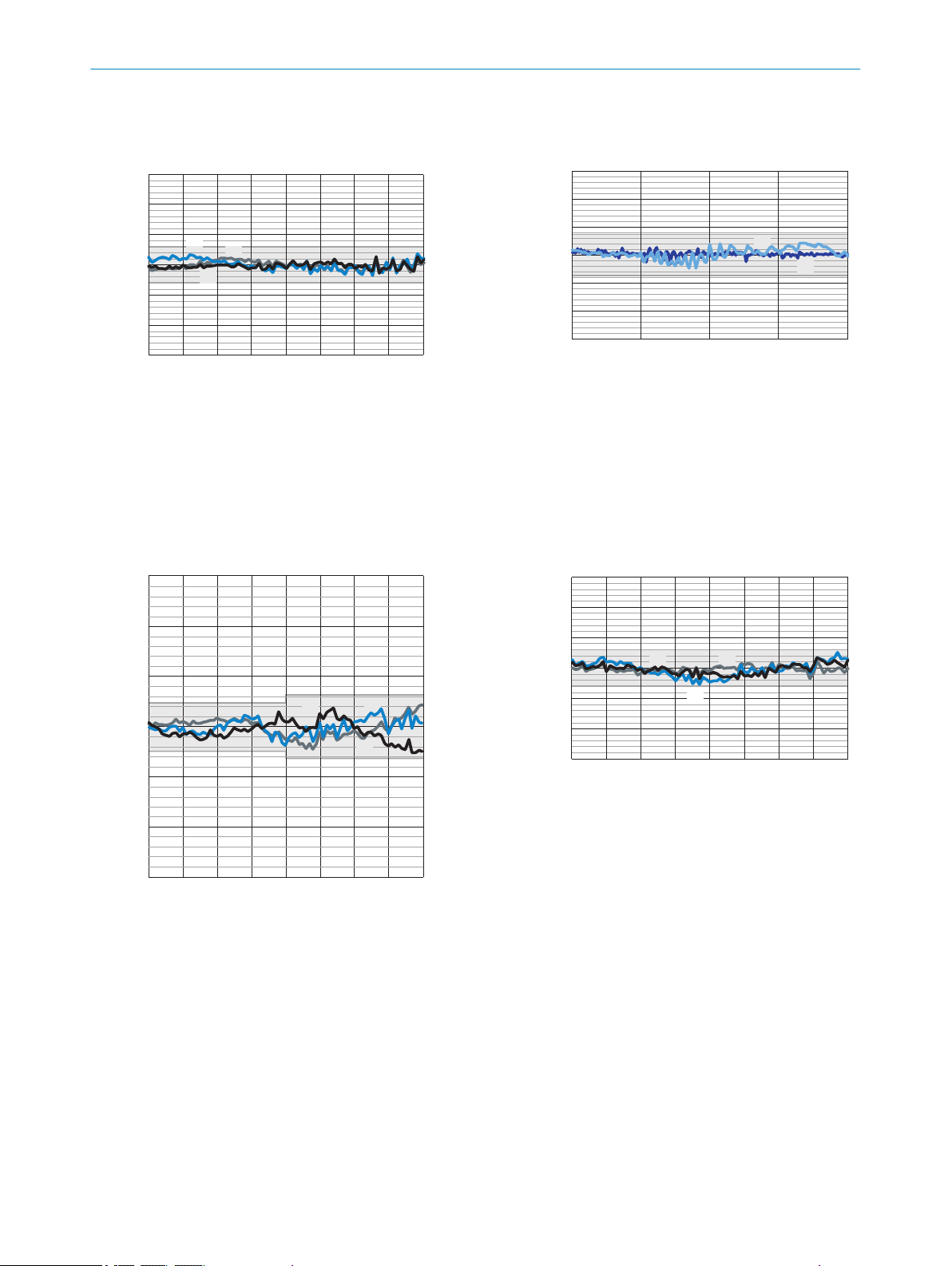
1
2
3
- 30
(- 1181.10)
- 20
(- 787.40)
- 10
(- 393.70)
0
10
(393.70)
20
(787.40)
30
(1181.10)
- 20
(- 0.79)
- 15
(- 0.59)
- 10
(- 0.39)
- 5
(- 0.20)
5
(0.20)10(0.39)15(0.59)
0 20
(0.79)
Linearity (μm)
Measured position mm (inch)
1
2
- 30
(- 1181.10)
- 20
(- 787.40)
- 10
(- 393.70)
0
10
(393.70)
20
(787.40)
30
(1181.10)
- 10
(- 0.39)
- 5
(- 0.20)
0 5
(0.20)
10
(0.39)
Linearity μm (μin)
Measured position mm (inch)
3
1
2
- 150
(- 5905.51)
- 100
(- 3937.00)
- 50
(- 1968.50)
0
50
(1968.50)
100
(3937.00)
150
(5905.51)
Linearity μm (μin)
Measured position mm (inch)
- 40
(- 1.57)
- 30
(- 1.18)
- 20
(- 0.79)
- 10
(- 0.39)
10
(0.39)20(0.79)30(1.18)
0 40
(1.57)
1
2
3
- 60
(- 2362.20)
- 40
(- 1574.80)
- 20
(- 787.40)
0
20
(787.40)
40
(1574.80)
60
(2362.20)
- 40
(- 1.57)
- 30
(- 1.18)
- 20
(- 0.79)
- 10
(- 0.39)
10
(0.39)20(0.79)30(1.18)
0 40
(1.57)
Linearity μm (μin)
Measured position mm (inch)
11 TECHNICAL DATA
OD5000-W85
Rubber, black (10% remission)
1
Ceramic, white (60% remission)
2
Stainless steel
3
OD5000-C150 and OD5000-W150
1
2
Glass
Reflector
1
2
3
74
Rubber, black (10% remission)
Ceramic, white (60% remission)
Stainless steel
O PE R AT I NG IN S TR U CT I ON S | OD5000 8021391//2017-10-06 | SICK
Rubber, black (10% remission)
1
Ceramic, white (60% remission)
2
Stainless steel
3
Subject to change without notice
Page 75

12 Accessories
NOTE
Accessories and where applicable mounting information can be found online at:
www.sick.com/OD5000
•
12.1 Recommended accessories
Designation Model name Part number
Y-distribution SYL-1208-G0M 6064008
Y-distribution extension cable DSC-1208-G02MA (2 m) 6064004
Supply cable DOL-1204-G02MAC 2088079
Ethernet cable SSL-2J04-G02ME 6034414
AOD1 connection cable DSL-2804-G02MC 6039180
ACCESSORIES 12
DSC-1208-G05MA (5 m) 6064005
DSC-1208-G10MA (10 m) 6064006
DSC-1208-G30MA (30 m) 6064007
8021391//2017-10-06 | SICK O PE R AT I NG IN S TR U CT I ON S | OD5000
Subject to change without notice
75
Page 76

13 ANNEX
13 Annex
13.1 EU declaration of conformity / Certificates
The EU declaration of conformity and other certificates can be downloaded from the
Internet at:
www.sick.com/OD5000
•
13.2 Licenses
SICK uses open-source software. This software is licensed by the rights holders using
the following licenses among others: the free licenses GNU General Public License (GPL
Version2, GPL Version3) and GNU Lesser General Public License (LGPL), the MIT
license, zLib license, and the licenses derived from the BSD license.
This program is provided for general use, but WITHOUT ANY WARRANTY OF ANY KIND.
This warranty disclaimer also extends to the implicit assurance of marketability or suita‐
bility of the program for a particular purpose.
More details can be found in the GNU General Public License. View the complete
license texts here: www.sick.com/licensetexts. Printed copies of the license texts are
also available on request.
76
O PE R AT I NG IN S TR U CT I ON S | OD5000 8021391//2017-10-06 | SICK
Subject to change without notice
Page 77

ANNEX 13
8021391//2017-10-06 | SICK O PE R AT I NG IN S TR U CT I ON S | OD5000
Subject to change without notice
77
Page 78

Further locations at www.sick.com
Australia
Phone +61 3 9457 0600
1800 334 802 – tollfree
E-Mail sales@sick.com.au
Austria
Phone +43 22 36 62 28 8-0
E-Mail office@sick.at
Belgium/Luxembourg
Phone +32 2 466 55 66
E-Mail info@sick.be
Brazil
Phone +55 11 3215-4900
E-Mail marketing@sick.com.br
Canada
Phone +1 905 771 14 44
E-Mail information@sick.com
Czech Republic
Phone +420 2 57 91 18 50
E-Mail sick@sick.cz
Chile
Phone +56 2 2274 7430
E-Mail info@schadler.com
China
Phone +86 20 2882 3600
E-Mail info.china@sick.net.cn
Denmark
Phone +45 45 82 64 00
E-Mail sick@sick.dk
Finland
Phone +358-9-2515 800
E-Mail sick@sick.fi
France
Phone +33 1 64 62 35 00
E-Mail info@sick.fr
Germany
Phone +49 211 5301-301
E-Mail info@sick.de
Hong Kong
Phone +852 2153 6300
E-Mail ghk@sick.com.hk
Hungary
Phone +36 1 371 2680
E-Mail office@sick.hu
India
Phone +91 22 6119 8900
E-Mail info@sick-india.com
Israel
Phone +972 4 6881000
E-Mail info@sick-sensors.com
Italy
Phone +39 02 274341
E-Mail info@sick.it
Japan
Phone +81 3 5309 2112
E-Mail support@sick.jp
Malaysia
Phone +6 03 8080 7425
E-Mail enquiry.my@sick.com
Mexico
Phone +52 (472) 748 9451
E-Mail mario.garcia@sick.com
Netherlands
Phone +31 30 2044 000
E-Mail info@sick.nl
New Zealand
Phone +64 9 415 0459
0800 222 278 – tollfree
E-Mail sales@sick.co.nz
Norway
Phone +47 67 81 50 00
E-Mail sick@sick.no
Poland
Phone +48 22 539 41 00
E-Mail info@sick.pl
Romania
Phone +40 356 171 120
E-Mail office@sick.ro
Russia
Phone +7 495 775 05 30
E-Mail info@sick.ru
Singapore
Phone +65 6744 3732
E-Mail sales.gsg@sick.com
Slovakia
Phone +421 482 901201
E-Mail mail@sick-sk.sk
Slovenia
Phone +386 591 788 49
E-Mail office@sick.si
South Africa
Phone +27 11 472 3733
E-Mail info@sickautomation.co.za
South Korea
Phone +82 2 786 6321
E-Mail info@sickkorea.net
Spain
Phone +34 93 480 31 00
E-Mail info@sick.es
Sweden
Phone +46 10 110 10 00
E-Mail info@sick.se
Switzerland
Phone +41 41 619 29 39
E-Mail contact@sick.ch
Taiwan
Phone +886 2 2375-6288
E-Mail sales@sick.com.tw
Thailand
Phone +66 2645 0009
E-Mail Ronnie.Lim@sick.com
Turkey
Phone +90 216 528 50 00
E-Mail info@sick.com.tr
United Arab Emirates
Phone +971 4 88 65 878
E-Mail info@sick.ae
United Kingdom
Phone +44 1727 831121
E-Mail info@sick.co.uk
USA
Phone +1 800 325 7425
E-Mail info@sick.com
Vietnam
Phone +84 945452999
E-Mail Ngo.Duy.Linh@sick.com
8021391//2017-10-06/en
SICK AG | Waldkirch | Germany | www.sick.com
 Loading...