

Page 1
OD1000
Displacement measurement sensor
O P E R A T I N G I N S T R U C T I O N S
Page 2

Product described
OD1000
Manufacturer
SICK AG
Erwin-Sick-Str. 1
79183 Waldkirch
Germany
Legal information
This work is protected by copyright. Any rights derived from the copyright shall be
reserved for SICK AG. Reproduction of this document or parts of this document is only
permissible within the limits of the legal determination of Copyright Law. Any modifica‐
tion, abridgment or translation of this document is prohibited without the express writ‐
ten permission of SICK AG.
The trademarks stated in this document are the property of their respective owner.
© SICK AG. All rights reserved.
Original document
This document is an original document of SICK AG.
2
O PE R AT I NG IN S TR U CT I ON S | OD1000 8019642/ZJW1/2017-04-03 | SICK
Subject to change without notice
Page 3

Contents
CONTENTS
1 About this document........................................................................ 6
1.1 Information on the operating instructions.............................................. 6
1.2 Explanation of symbols............................................................................ 6
1.3 Scope of delivery....................................................................................... 6
1.4 Customer service...................................................................................... 7
2 Safety information............................................................................ 8
2.1 Intended use............................................................................................. 8
2.2 Improper use............................................................................................. 8
2.3 Limitation of liability................................................................................. 8
2.4 Modifications and conversions................................................................ 8
2.5 Requirements for skilled persons and operating personnel.................. 9
2.6 Operational safety and particular hazards.............................................. 9
2.6.1 Laser radiation......................................................................... 9
2.7 Warning signs on the device.................................................................... 10
3 Product description........................................................................... 11
3.1 Product characteristics............................................................................ 11
3.2 Setup and dimensions............................................................................. 12
3.3 Product ID.................................................................................................. 12
4 Transport and storage....................................................................... 14
4.1 Transport................................................................................................... 14
4.2 Unpacking.................................................................................................. 14
4.3 Transport inspection................................................................................. 14
4.4 Storage...................................................................................................... 14
5 Mounting............................................................................................. 15
5.1 Mounting instructions............................................................................... 15
5.2 Mounting device....................................................................................... 15
6 Electrical installation........................................................................ 16
6.1 Safety......................................................................................................... 16
6.2 Wiring notes.............................................................................................. 16
6.3 Connecting the device electrically........................................................... 18
7 Operation............................................................................................ 20
7.1 General notes............................................................................................ 20
7.2 Control elements and status indicators.................................................. 20
7.2.1 Indicator lights......................................................................... 20
7.2.2 Operating buttons.................................................................... 21
7.3 Operating concept.................................................................................... 21
8 Operation via display........................................................................ 22
8.1 Menu structure and parameter description............................................ 22
8019642/ZJW1/2017-04-03 | SICK OP E RA T IN G I N ST R UC T IO N S | OD1000
Subject to change without notice
3
Page 4

CONTENTS
8.1.1 Main display level and main menu......................................... 22
8.1.2 Measurement menu group..................................................... 23
8.1.3 I/O interface menu group: Q1 output..................................... 24
8.1.4 I/O interface menu group: Q2/Qa output, In1 input............. 25
8.1.5 Device menu group.................................................................. 26
8.1.6 Communication menu group.................................................. 26
8.1.7 Info menu group...................................................................... 26
8.2 Main display level..................................................................................... 26
8.3 Measurement............................................................................................ 27
8.3.1 Application settings................................................................. 27
8.3.2 Default settings........................................................................ 32
8.4 I/O interface.............................................................................................. 37
8.4.1 Q1 output................................................................................. 37
8.4.2 Q2/Qa output............................................................................
8.4.3 In1 input................................................................................... 46
8.5 Device........................................................................................................ 51
8.5.1 User level.................................................................................. 51
8.5.2 Reset........................................................................................ 51
8.5.3 Saving customer settings........................................................ 51
8.5.4 Language.................................................................................. 52
8.5.5 Display settings........................................................................ 52
8.5.6 Measurement laser................................................................. 52
8.6 Communication......................................................................................... 53
8.7 Info............................................................................................................. 53
8.7.1 Firmware verification............................................................... 53
8.7.2 Serial number.......................................................................... 53
8.7.3 Sensor operating hours........................................................... 53
8.7.4 Laser operating hours............................................................. 54
8.7.5 Sensor status........................................................................... 54
8.7.6 Part number............................................................................. 54
43
9 Operation via IO-Link........................................................................ 55
9.1 Process data............................................................................................. 55
9.2 Device data............................................................................................... 55
10 Operation via SOPAS ET................................................................... 56
11 Maintenance...................................................................................... 58
11.1 Cleaning..................................................................................................... 58
11.2 Maintenance............................................................................................. 58
12 Troubleshooting................................................................................. 59
12.1 General faults, warnings, and errors....................................................... 59
12.2 Detecting and displaying errors............................................................... 59
12.3 Information for service cases.................................................................. 60
12.4 Returns...................................................................................................... 60
4
O PE R AT I NG IN S TR U CT I ON S | OD1000 8019642/ZJW1/2017-04-03 | SICK
Subject to change without notice
Page 5

CONTENTS
12.5 Repairs...................................................................................................... 60
12.6 Disposal..................................................................................................... 60
13 Technical data.................................................................................... 62
13.1 Performance............................................................................................. 62
13.2 Interfaces.................................................................................................. 63
13.3 Mechanics/electronics............................................................................. 63
13.4 Ambient data............................................................................................. 64
14 Accessories........................................................................................ 65
14.1 Accessories............................................................................................... 65
15 Annex.................................................................................................. 66
15.1 EU declaration of conformity / Certificates............................................. 66
15.2 Licenses.................................................................................................... 66
15.2.1 .................................................................................................. 66
8019642/ZJW1/2017-04-03 | SICK OP E RA T IN G I N ST R UC T IO N S | OD1000
Subject to change without notice
5
Page 6
1 ABOUT THIS DOCUMENT
1 About this document
1.1 Information on the operating instructions
These operating instructions provide important information on how to handle the prod‐
uct from SICK AG. Adherence to all the specified safety notes and guidelines is a pre‐
requisite for working safely. You must also comply with any local work safety regulations
and general safety specifications applicable to the use of the product.
Ensure that you read through these operating instructions carefully before starting any
work. They constitute an integral part of the product and should be stored in the direct
vicinity of the product so they remain accessible to personnel at all times. If the product
is passed on to a third party, these operating instructions should be handed over with
it.
These operating instructions do not provide information on operating the machine in
which the product is integrated. For information about this, refer to the operating
instructions of the particular machine.
1.2 Explanation of symbols
Warnings and important information in this document are labeled with symbols. The
warnings are introduced by signal words that indicate the extent of the danger. These
warnings must be observed at all times and care must be taken to avoid accidents, per‐
sonal injury, and material damage.
DANGER
… indicates a situation of imminent danger, which will lead to a fatality or serious inju‐
ries if not prevented.
WARNING
… indicates a potentially dangerous situation, which may lead to a fatality or serious
injuries if not prevented.
CAUTION
… indicates a potentially dangerous situation, which may lead to minor/slight injuries if
not prevented.
NOTICE
… indicates a potentially harmful situation, which may lead to material damage if not
prevented.
NOTE
… highlights useful tips and recommendations as well as information for efficient and
trouble-free operation.
1.3 Scope of delivery
Supplied documentation:
■
SafetyNotes
6
O PE R AT I NG IN S TR U CT I ON S | OD1000 8019642/ZJW1/2017-04-03 | SICK
Subject to change without notice
Page 7

NOTE
All available documentation can be found online at
www.sick.com/OD1000
b
1.4 Customer service
If you require any technical information, our customer service department will be happy
to help. To find your representative, see the final page of this document.
NOTE
Before calling, make a note of all type label data such as type code, serial number, etc.,
to ensure faster processing.
ABOUT THIS DOCUMENT 1
8019642/ZJW1/2017-04-03 | SICK OP E RA T IN G I N ST R UC T IO N S | OD1000
Subject to change without notice
7
Page 8
2 SAFETY INFORMATION
2 Safety information
2.1 Intended use
The displacement measurement sensor is an opto-electronic measuring device and is
used for optical, non-contact distance measurement between the displacement meas‐
urement sensor and an object.
The required optical properties of the object that will be detected are specified in the
technical data section of this document.
SICK AG assumes no liability for losses or damage arising from the use of the product,
either directly or indirectly. This applies in particular to use of the product that does not
conform to its intended purpose and is not described in this documentation.
2.2 Improper use
Any use outside of the stated areas, in particular use outside of the technical specifica‐
tions and the requirements for intended use, will be deemed to be incorrect use.
The device does not constitute a safety-relevant device according to the EC Machi‐
•
nery Directive (2006/42/EC).
The device must not be used in explosion-hazardous areas, in corrosive environ‐
•
ments or under extreme environmental conditions.
Any use of accessories not specifically approved by SICK AG is at your own risk.
•
WARNING
Danger due to improper use!
Any improper use can result in dangerous situations.
Therefore, observe the following information:
■
Device should be used only in accordance with its intended use.
■
All information in these operating instructions must be strictly observed.
2.3 Limitation of liability
Applicable standards and regulations, the latest state of technological development,
and our many years of knowledge and experience have all been taken into account
when assembling the data and information contained in these operating instructions.
The manufacturer accepts no liability for damage caused by:
■
Failing to observe the operating instructions
■
Incorrect use
■
Use by untrained personnel
■
Unauthorized conversions
■
Technical modifications
■
Use of unauthorized spare parts, consumables, and accessories
With special variants, where optional extras have been ordered, or owing to the latest
technical changes, the actual scope of delivery may vary from the features and illustra‐
tions shown here.
2.4 Modifications and conversions
NOTICE
Modifications and conversions to the device may result in unforeseeable dangers.
8
O PE R AT I NG IN S TR U CT I ON S | OD1000 8019642/ZJW1/2017-04-03 | SICK
Subject to change without notice
Page 9
Interrupting or modifying the device or SICK software will invalidate any warranty claims
against SICK AG. This applies in particular to opening the housing, even as part of
mounting and electrical installation.
2.5 Requirements for skilled persons and operating personnel
WARNING
Risk of injury due to insufficient training.
Improper handling of the device may result in considerable personal injury and material
damage.
■
All work must only ever be carried out by the stipulated persons.
The operating instructions state the following qualification requirements for the various
areas of work:
■
Instructed personnel have been briefed by the operator about the tasks assigned
to them and about potential dangers arising from improper action.
■
Skilled personnel have the specialist training, skills, and experience, as well as
knowledge of the relevant regulations, to be able to perform tasks delegated to
them and to detect and avoid any potential dangers independently.
■
Electricians have the specialist training, skills, and experience, as well as knowl‐
edge of the relevant standards and provisions to be able to carry out work on elec‐
trical systems and to detect and avoid any potential dangers independently. In Ger‐
many, electricians must meet the specifications of the BGV A3 Work Safety Regu‐
lations (e.g. Master Electrician). Other relevant regulations applicable in other
countries must be observed.
SAFETY INFORMATION 2
The following qualifications are required for various activities:
Table 1: Activities and technical requirements
Activities Qualification
Mounting, maintenance
Electrical installation,
device replacement
Commissioning, configura‐
tion
Operation of the device for
the particular application
Basic practical technical training
■
Knowledge of the current safety regulations in the workplace
■
Practical electrical training
■
Knowledge of current electrical safety regulations
■
Knowledge of the operation and control of the devices in
■
their particular application
Basic knowledge of the WindowsTM operating system in use
■
Basic knowledge of the design and setup of the described
■
connections and interfaces
Basic knowledge of data transmission
■
Knowledge of the operation and control of the devices in
■
their particular application
Knowledge of the software and hardware environment for
■
the particular application
2.6 Operational safety and particular hazards
Please observe the safety notes and the warnings listed here and in other chapters of
these operating instructions to reduce the possibility of risks to health and avoid dan‐
gerous situations.
2.6.1 Laser radiation
The device is equipped with a laser source:
8019642/ZJW1/2017-04-03 | SICK OP E RA T IN G I N ST R UC T IO N S | OD1000
Subject to change without notice
9
Page 10

2 SAFETY INFORMATION
■
Measurement laser (red, visible to the human eye)
CAUTION
Optical radiation: Laser class 1
The accessible radiation does not pose a danger when viewed directly for up to
100 seconds. It may pose a danger to the eyes and skin in the event of incorrect
use.
■
Do not open the housing. Opening the housing will not switch off the laser.
Opening the housing may increase the level of risk.
■
Current national regulations regarding laser protection must be observed.
The laser qualifies as a class 1 laser based on standard IEC 60825-1: 2014
(Safety of laser products - Part 1: Equipment classification and requirements,
Edition 3).
2.7 Warning signs on the device
A visible red laser is installed in the device. The laser corresponds to laser class 1. The
housing is labeled with a warning sign.
10
O PE R AT I NG IN S TR U CT I ON S | OD1000 8019642/ZJW1/2017-04-03 | SICK
Subject to change without notice
Page 11
3 Product description
3.1 Product characteristics
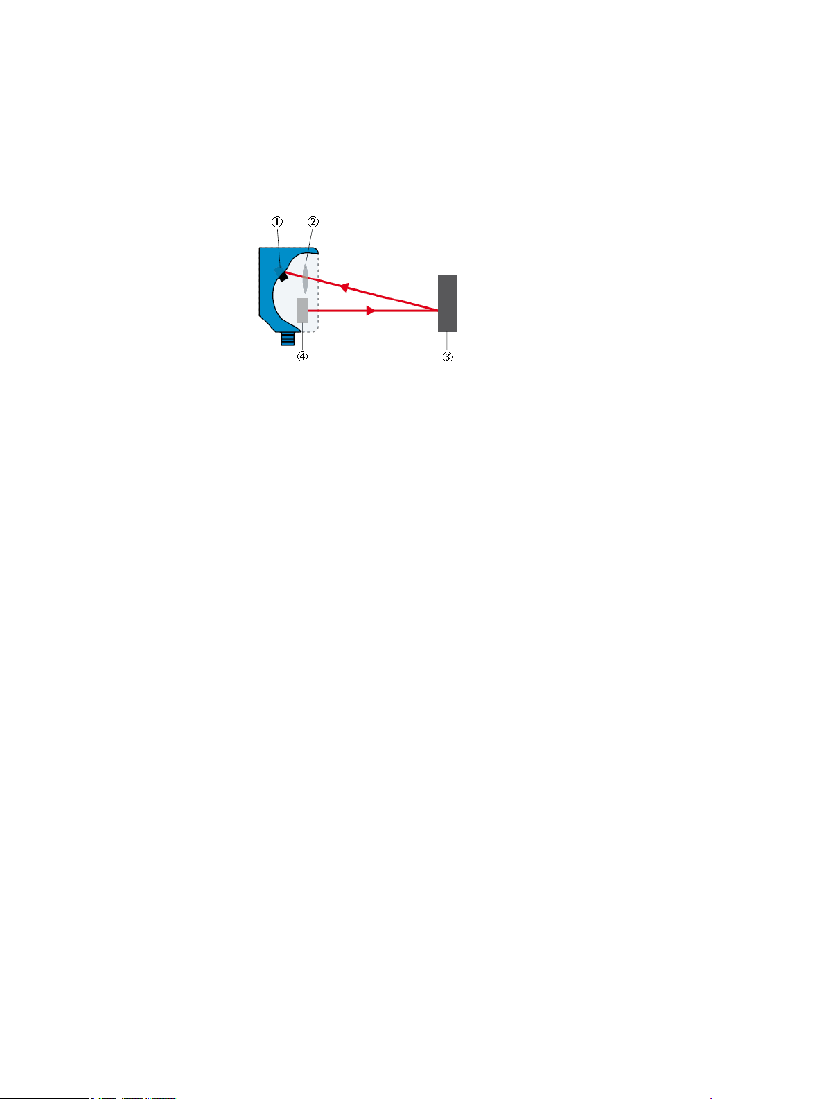
The displacement measurement sensor uses the triangulation principle for distance
measurement. This technology makes it possible to measure the distance between the
displacement measurement sensor and an object.
Figure 1: Triangulation principle
Receiver
1
Lens
2
Object
3
Laser
4
PRODUCT DESCRIPTION
3
A point of light is projected onto the measuring object. The light reflected is captured by
a light-sensitive receiver at a specific angle. Based on the angle between the send and
receive direction, the position of the object is triangulated (lat. Triangulum: triangle).
The distance determined is transmitted via the IO-Link interface. The analog signal out‐
put converts the distance value into an output signal proportional to the distance
(switchable: mA/V).
Digital switching outputs can be used to monitor when configured thresholds/distance
values have been reached. The “Distance to the object”, “Window”, and “ObSB” switch‐
ing functions are supported.
Measured distance values can be visualized and parameter settings can be made
using the graphical OLED display. Alternatively, the displacement measurement sensor
can be configured via the IO-Link interface in conjunction with an IO-Link master. The
SOPAS user interface can be used for configuration as well. This process also takes
place via the IO-Link interface in conjunction with an IO-Link master. For more informa‐
tion visit:
www.sick.com/SOPAS_ET
8019642/ZJW1/2017-04-03 | SICK OP E RA T IN G I N ST R UC T IO N S | OD1000
Subject to change without notice
11
Page 12
71.5 (2.81)
60.7 (2.39)
58.55 (2.31)
22.5
(0.89)
53.2 (2.09)
11.95
(0.47)
∅ 4.5 (0.18)
4.5 (0.18)
3 (0.12)
15.2
(0.60)
PWR
Q1
Q2
M12 x 1
2
1
6
9
78
4
5
2
25.9
(1.02)
3
3 PRODUCT DESCRIPTION
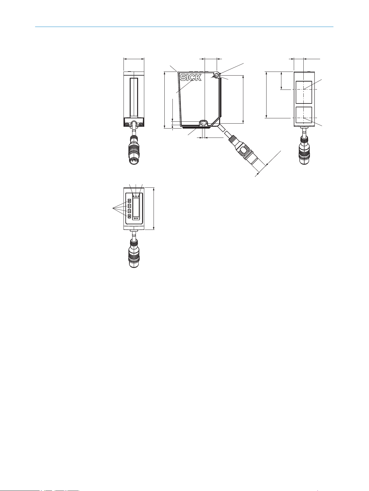
3.2 Setup and dimensions
3.3 Product ID
Figure 2: Setup and dimensions
Device zero point (distance = 0 mm)
1
Fixing holes (for M4)
2
Ventilation opening – do not cover!
3
Center of optical axis, receiver
4
Center of optical axis, sender
5
Display LED, green
6
7
8
9
Display LED, yellow
Display LED, yellow
Display operating elements
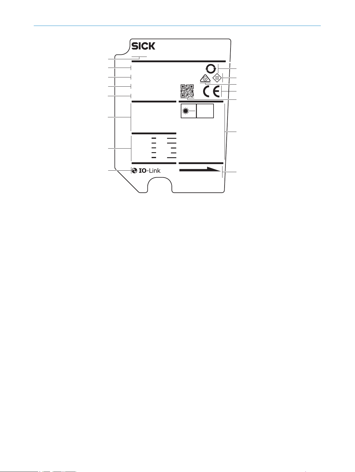
Type label
The following information can be read off the device from the type label:
12
O PE R AT I NG IN S TR U CT I ON S | OD1000 8019642/ZJW1/2017-04-03 | SICK
Subject to change without notice
Page 13
1
6
8
2
9
ß
à
á
ã
â
7
ä
SICK AG
D-791 83 Waldkirc h
Made in Germa ny
OD1000
OD1000-6001R15
1 075 638
SN16100001
MAR 2016
EN/IEC 60825-1:2014
Complies with 21 CFR
1040.10 and 1040.11
except for deviations
pursuant to laser
notice No. 50, dated
June 24, 2007
CLASS 1 LASER PRODUCT
DC 18 - 30 Vdc class 2
Qout: < 100 mA
QAout: 4 - 20 mA/0 - 10 V
Amb. Temp.: < 50 °C
Power Con.: < 2.5 W
Enclosure Type: 1
brown
blue
black
white
gray
1
3
4
2
5
LASER APERTURE
L+
M
Q1/C
Q2/Q
A
In1
LASER
1
5
25
3
4
PRODUCT DESCRIPTION 3
Figure 3: OD1000 type label
1
2
3
4
5
6
7
8
9
ß
à
á
â
ã
ä
Device display
The following information can be called up using the info menu on the device display:
Firmware verification
•
Serial number
•
Sensor operating hours
•
Laser operating hours
•
Sensor status (error history)
•
Part number
•
EFUP information for China
Protection class
RCM conformity mark
EU conformity mark
2D code with part number and serial number
Laser information
Laser radiation direction
IO-Link symbol
Pin assignment
Electrical data and environmental data
Month and year of manufacture
Serial number
Part number
Type code
Device family
8019642/ZJW1/2017-04-03 | SICK OP E RA T IN G I N ST R UC T IO N S | OD1000
Subject to change without notice
13
Page 14

4 TRANSPORT AND STORAGE
4 Transport and storage
4.1 Transport
For your own safety, please read and observe the following notes:
NOTICE
Damage to the product due to improper transport.
■
The device must be packaged for transport with protection against shock and
damp.
■
Recommendation: Use the original packaging as it provides the best protection.
■
Transport should be performed by trained specialist staff only.
■
The utmost care and attention is required at all times during unloading and trans‐
portation on company premises.
■
Note the symbols on the packaging.
■
Do not remove packaging until immediately before you start mounting.
4.2
Unpacking
■
Before unpacking, it may be necessary to equalize the temperature to protect the
device from condensation.
■
Handle the device with care and protect it from mechanical damage.
4.3 Transport inspection
Immediately upon receipt in Goods-in, check the delivery for completeness and for any
damage that may have occurred in transit. In the case of transit damage that is visible
externally, proceed as follows:
■
Do not accept the delivery or only do so conditionally.
■
Note the scope of damage on the transport documents or on the transport compa‐
ny's delivery note.
■
File a complaint.
NOTE
Complaints regarding defects should be filed as soon as these are detected. Damage
claims are only valid before the applicable complaint deadlines.
4.4 Storage
Store the device under the following conditions:
■
Recommendation: Use the original packaging.
■
Do not store outdoors.
■
Store in a dry area that is protected from dust.
■
So that any residual damp can evaporate, do not package in airtight containers.
■
Do not expose to any aggressive substances.
■
Protect from sunlight.
■
Avoid mechanical shocks.
■
Storage temperature: see "Technical data", page 62.
■
For storage periods of longer than 3 months, check the general condition of all
components and packaging on a regular basis.
14
O PE R AT I NG IN S TR U CT I ON S | OD1000 8019642/ZJW1/2017-04-03 | SICK
Subject to change without notice
Page 15

5 Mounting
5.1 Mounting instructions
Observe the technical data.
•
Protect the sensor from direct sunlight.
•
To prevent condensation, avoid exposing the sensor to rapid changes in tempera‐
•
ture.
The mounting site has to be designed for the weight of the device.
•
To avoid inaccurate measurements when installing multiple devices: Make sure
•
that the laser light spot of one device is not in the visible range of another device.
Only commission the device 30 minutes after switching it on. Measured values
•
which are taken immediately after the device is switched on are not reliable.
5.2 Mounting device
1. Mount the displacement measurement sensor using the designated fixing holes,
see "Setup and dimensions", page 12.
2. Make the electrical connection. Attach and tighten a voltage-free cable, see "Con‐
necting the device electrically", page 18.
3. Switch on the supply voltage.
✓
The green operating LED lights up.
The device needs around 10 seconds of initialization time before it is ready for
operation.
4. Align the light spot so that the desired object is measured.
MOUNTING 5
8019642/ZJW1/2017-04-03 | SICK OP E RA T IN G I N ST R UC T IO N S | OD1000
Subject to change without notice
15
Page 16
6 ELE
CTRICAL INSTALLATION
6 Electrical installation
6.1 Safety
WARNING
P
ersonal injury due to incorrect supply voltage.
An incorrect supply voltage may result in personal injury.
■
Only operate the device using safety extra-low voltage and safe electrical insula‐
tion as per protection class III.
NOTICE
E
quipment damage or unpredictable operation due to working with live parts.
Working with live parts may result in unpredictable operation.
■
Only carry out wiring work when the power is off.
■
Only connect and disconnect electrical connections when the power is off.
6.2 Wiring notes
NOTICE
aults due to incorrect wiring.
F
Incorrect wiring may result in operational faults.
■
Follow the wiring notes precisely.
NOTE
Preassembled cables can be found online at:
www.sick.com/OD1000
b
The electrical connection of the device is configured as an M12 round connector. The
otection class stated in the technical data is achieved only with a screwed plug con‐
pr
nector or cover cap.
Please observe the following wiring notes:
■
A correct and complete cable shielding design is required for trouble-free data
transmission.
■
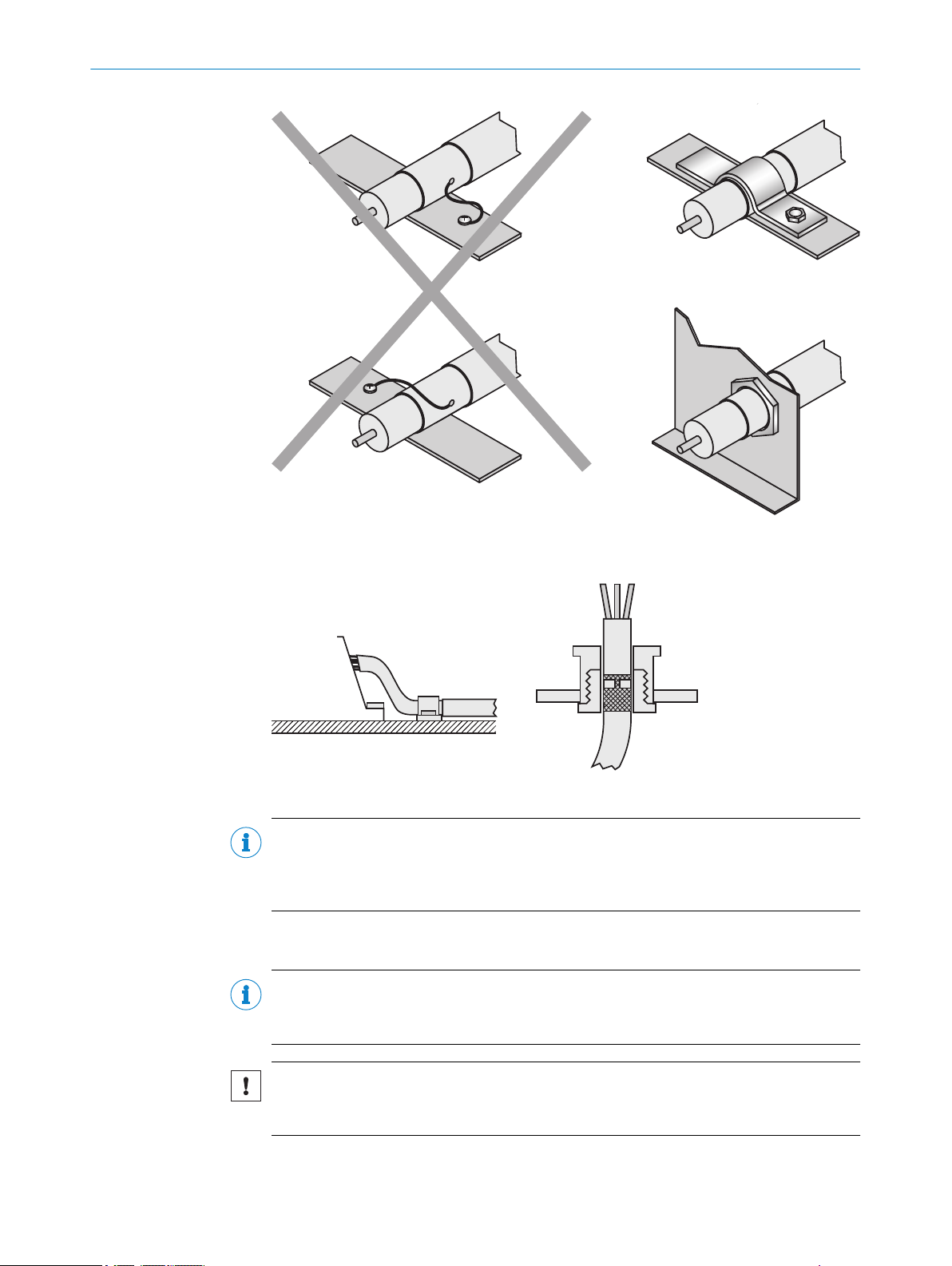
The cable shield must be connected at both ends in the control cabinet and at the
device. The cable shield of the pre-assembled cables is connected to the knurled
nut and thus also to a large area of the device housing.
■
The cable shield in the control cabinet must be connected to a large area of the
signal ground, see figure 7.
■
Appropriate measures must be taken to prevent equipotential bonding currents
flowing through the cable shield.
■
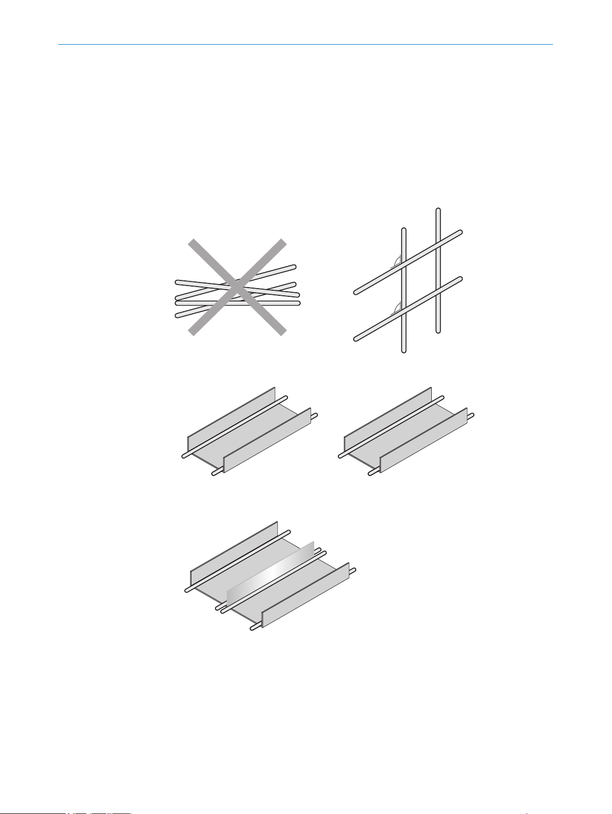
During installation, pay attention to the different cable groups. The cables are
grouped into the following 4 groups according to their sensitivity to interference or
radiated emissions.
16
Group 1: Cables very sensitive to interference, such as analog measuring
°
cables
Group 2: Cables sensitive to interference, such as device cables, communica‐
°
tion signals, bus signals
O PE R AT I NG IN S TR U CT I ON S | OD1000 8019642/ZJW1/2017-04-03 | SICK
Subject to change without notice
Page 17
1
2
4
3
1
2
4
3
90
90
1
2
3
4
1
2
3
4
ELECTRICAL INSTALLATION
Group 3: Cables which are a source of interference such as control cables for
°
inductive loads, motor brakes
Group 4: Cables which are powerful sources of interference, such as output
°
cables from frequency inverters, welding system power supplies, power
cables
Cables in groups 1, 2 and 3, 4 must be crossed at right angles (see figure 4).
w
Route the cables in groups 1, 2 and 3, 4 in different cable channels or use
w
metallic separators (see figure 5 and see figure 6). This applies particularly if
cables of devices with a high level of radiated emission, such as frequency
converters, are laid parallel to device cables.
6
Figure 4: Cross cables at right angles
Figure 5: Ideal laying ‑ Place cables in different cable channels
Figure 6: Alternative laying – Separate cables with metallic separators
8019642/ZJW1/2017-04-03 | SICK OP E RA T IN G I N ST R UC T IO N S | OD1000
Subject to change without notice
17
Page 18
6 ELECTRICAL INSTALLATION
Figure 7: Make an extensive and low-impedance ground connection of the cable shield in the
control cabinet.
Figure 8: Shield connection in plastic housings
NOTE
Prevent equipotential bonding currents via the cable shield with a suitable grounding
concept. If necessary, ground currents on the EtherNet/IP cabling can be prevented by
the use of an EtherNet/IP adapter (part number 2044264).
6.3 Connecting the device electrically
NOTE
The connection diagram, and information on inputs and outputs, can be found on the
side plate on the device.
18
NOTICE
All electrical circuits must be connected to the device with safety extra-low voltage
(SELV or PELV).
O PE R AT I NG IN S TR U CT I ON S | OD1000 8019642/ZJW1/2017-04-03 | SICK
Subject to change without notice
Page 19
1
4 3
5
2
L+
1
brn
M
3
blu
Q1/C
4
blk
QA/Q2/¯Q1
2
wht
In1
5
gra
ELECTRICAL INSTALLATION 6
1. Ensure that the voltage supply is not connected.
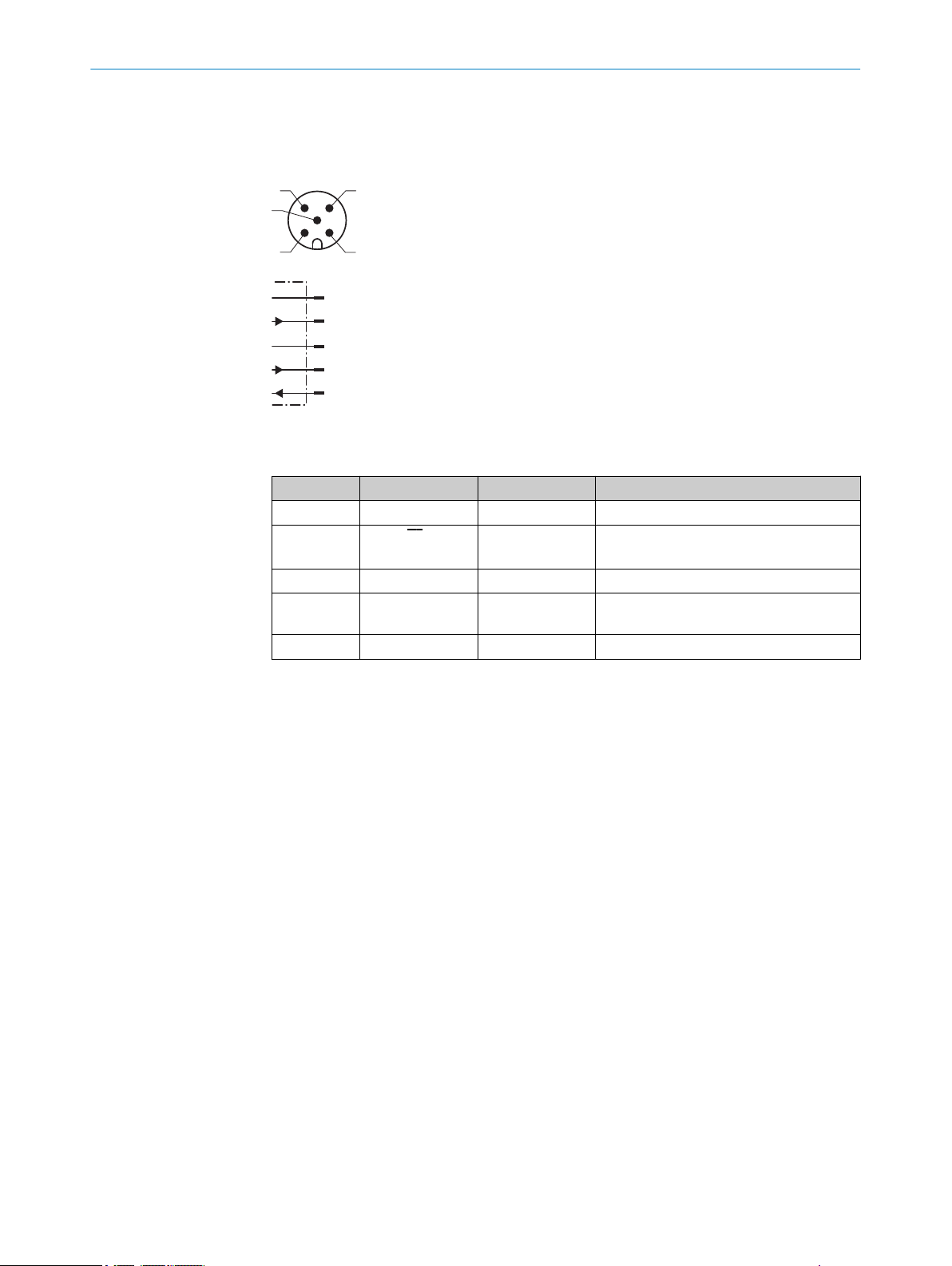
2. Connect the device according to the connection diagram.
3. Observe the wiring instructions, see "Wiring notes", page 16.
Figure 9: Connection diagram, 5-pin male connector
Table 2: Legend for connection diagram
Contact Identification Wire color Description
1 L+ Brown Supply voltage: +18 ... +30 V DC
2 QA/Q2/Q
1
3 M Blue Supply voltage: 0 V
4 Q1/C Black Output 1: switching output 1 (push-pull
5 In1 Gray Input 1
White Output 2: analog output / switching out‐
put 2 (push-pull stage) / Q1 not
stage) / IO-Link
8019642/ZJW1/2017-04-03 | SICK OP E RA T IN G I N ST R UC T IO N S | OD1000
Subject to change without notice
19
Page 20
PWR
Q1
Q2
1
4
2
3
7 OPERATION
7 Operation
7.1 General notes
If the device is not able to perform a measurement even though the measuring object is
within the specified measuring range, the alignment should be checked and optimized
if necessary. In general, adjusting the measuring rate can increase the measuring abil‐
ity for very dark objects, for example.
For a successful teach operation, the device must be able to measure. The distance to
the teach object must not change during the teach operation. The object must be in the
measuring range, and the distance values taught in for the distance near to the sensor
and the distance far from the sensor must not be exactly the same during a switching
window or the analog scaling.
To prevent EMC interference, observe the wiring instructions. If an environment is dis‐
rupted by EMC interference, data output via IO-Link is the preferred solution. If the
application requires an output of the measured values in such an environment via the
analog output, an analog current output should also be preferred to using the voltage
output, because this is significantly less susceptible to EMC interference.
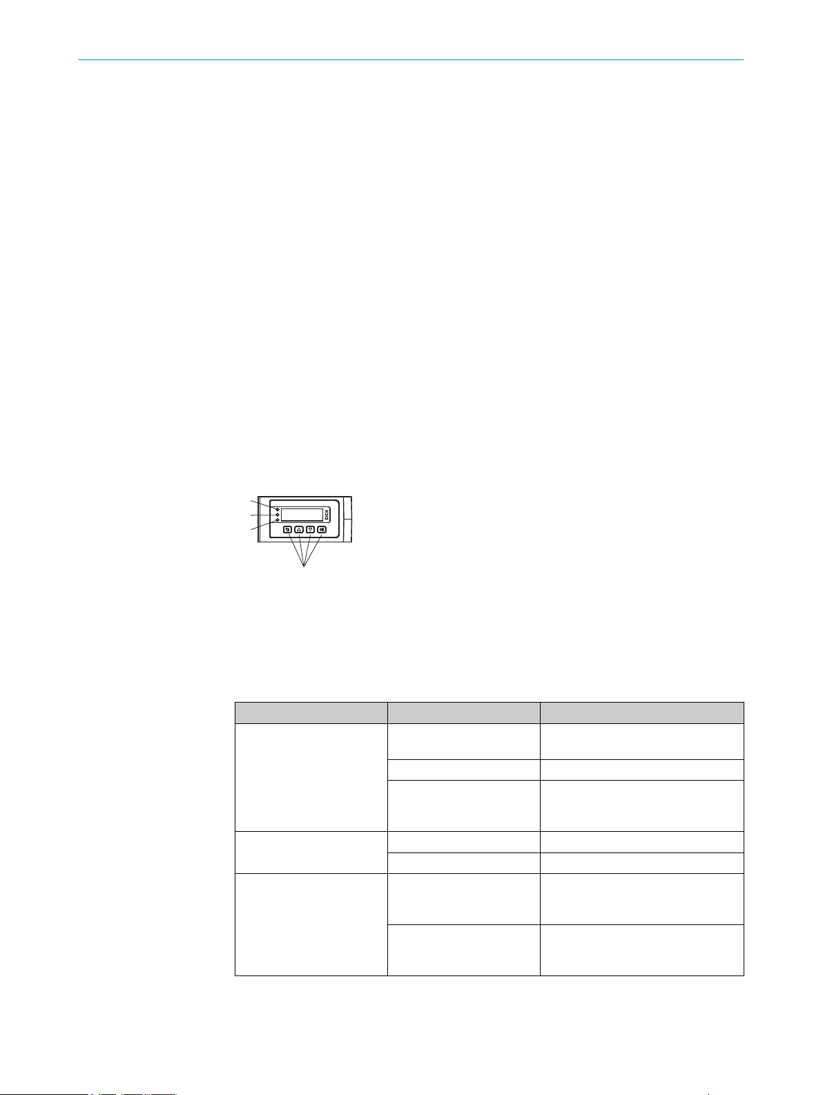
7.2 Control elements and status indicators
7.2.1 Indicator lights
Status-LED PWR (grün)
1
Status-LED Q1 (orange)
2
Status-LED Q2 (orange)
3
Bedientasten
4
Table 3: Meaning of the indicator lights
Display Status Meaning
PWR status indicator
Output display Q
Output display Q
1
2
O
o
Ö
O
o
O
o
Voltage supply available, device
ready for use
Voltage supply not available
Voltage supply available, device
ready for use, connection to an IOLink master available
Switching output active
Switching output not active
Switching output active or measured
value within the scaling range for the
analog output
Switching output not active or meas‐
ured value outside the scaling range
for the analog output
20
O PE R AT I NG IN S TR U CT I ON S | OD1000 8019642/ZJW1/2017-04-03 | SICK
Subject to change without notice
Page 21
Display Status Meaning
Output displays Q
o
Ö
O
7.2.2 Operating buttons
Pushbutton Function Description
Does not light up
Flashing
Permanently on
Open menu/
confirm
Cancel Switches to the previous menu level.
Navigate Switches between multiple screens on one menu level.
Navigate Switches between multiple screens on one menu level.
OPERATION 7
1
Ö Ö Simultaneous
Ö Ö 5 seconds in alter‐
nation
Ö Ö Permanently in
alternation
Opens the menu, confirms entries, or switches to the next menu
level of a selected element.
Moves the cursor to the right when entering numbers.
Moves the cursor to the left when entering numbers.
Increases the value when entering numbers.
Reduces the value when entering numbers.
Teach-in operation is carried out
Teach-in operation has failed
There is a fault
Activating / Deactivating the operating button lock
The operating buttons can be locked / unlocked using a shortcut in order to prevent
accidental operation:
b
Press and hold the and pushbuttons simultaneously for > 3 seconds.
✓
When the pushbutton lock is activated, the padlock symbol appears in the dis‐
play. When the pushbutton lock is deactivated, the padlock symbol is not dis‐
played.
NOTE
The operating button lock can also be activated / deactivated via SOPAS ET or IO-Link.
7.3 Operating concept
The device can be operated using the following methods:
Display and operating buttons on the device, see "Operation via display",
•
page 22.
SOPAS ET user interface (PC), see "Operation via SOPAS ET", page 56.
•
IO-Link, see "Operation via IO-Link", page 55.
•
8019642/ZJW1/2017-04-03 | SICK OP E RA T IN G I N ST R UC T IO N S | OD1000
Subject to change without notice
21
Page 22

8 OPERATION VIA DISPLAY
8 Operation via display
NOTE
Only certain functions are available depending on the user level set (see see "User
level", page 51):
Easy: frequently required functions (factory setting)
•
Advanced: all available functions
•
8.1 Menu structure and parameter description
8.1.1 Main display level and main menu
22
O PE R AT I NG IN S TR U CT I ON S | OD1000 8019642/ZJW1/2017-04-03 | SICK
Subject to change without notice
Page 23

8.1.2 Measurement menu group
OPERATION VIA DISPLAY 8
8019642/ZJW1/2017-04-03 | SICK OP E RA T IN G I N ST R UC T IO N S | OD1000
Subject to change without notice
23
Page 24

8 OPERATION VIA DISPLAY
8.1.3 I/O interface menu group: Q1 output
24
O PE R AT I NG IN S TR U CT I ON S | OD1000 8019642/ZJW1/2017-04-03 | SICK
Subject to change without notice
Page 25

8.1.4 I/O interface menu group: Q2/Qa output, In1 input
OPERATION VIA DISPLAY 8
8019642/ZJW1/2017-04-03 | SICK OP E RA T IN G I N ST R UC T IO N S | OD1000
Subject to change without notice
25
Page 26

8 OPERATION VIA DISPLAY
8.1.5 Device menu group
8.1.6 Communication menu group
8.1.7 Info menu group
8.2 Main display level
As soon as voltage is supplied to the device, the display shows the main display level
and a measured value is displayed.
26
The / pushbuttons can be used to switch between the following displays:
O PE R AT I NG IN S TR U CT I ON S | OD1000 8019642/ZJW1/2017-04-03 | SICK
Subject to change without notice
Page 27

OPERATION VIA DISPLAY 8
Relative distance measured value:
•
The (relative) distance value always takes into account the set measured value off‐
set.
Absolute and relative distance measured value:
•
Simultaneous display of the distance without (absolute) and with (relative) the set
measured value offset.
Scaled analog value:
•
The current output value is only displayed when the analog output is activated.
Signal level:
•
NOTE
The signal level corresponds to the amount of light received by the device's
receiver optics. This is a dimensionless value. It essentially depends on the dis‐
tance from the measuring object, the surface of the measuring object (color,
roughness/gloss, angle to the optical axis), and the cycle time set on the device.
To enable the device to measure the distance correctly, the signal level must not
drop below a lower limit value. The dynamics of the device normally regulate the
level to ensure an optimized value. Depending on the set cycle time, object proper‐
ties, and object distance, the signal level may drop below the lower limit value and
make it impossible to carry out a measurement. It may be possible to improve the
measuring behavior by increasing the cycle time, optimizing the alignment of the
device with the object, or reducing the distance to the measuring object.
Distance visualization:
•
The cursor gives a qualitative indication of the position within the maximum meas‐
uring range.
Temperature:
•
The value displays the temperature inside the device and is not relevant for the
specified operating temperature range.
8.3 Measurement
8.3.1 Application settings
The functions are only available in the Advanced user level, see "Device", page 51.
8019642/ZJW1/2017-04-03 | SICK OP E RA T IN G I N ST R UC T IO N S | OD1000
Subject to change without notice
27
Page 28

Max. measuring range
Transparent
screen
Distance rangeNear limit Far limit
15 mm
Tolerance window
15 mm
Tolerance window
Reliable detectionReliable blanking Reliable
blanking
Measuring object
OPERATION VIA DISPLAY
8
8.3.1.1 Distance range
The “Distance range” function can be used to define an evaluation range in which the
device measures object distances. All surrounding ranges are blanked. A typical appli‐
cation is the blanking of a transparent protective screen fitted between the object and
the device.
During configuration, please note that the application must take into account a toler‐
ance range of 15 mm outside the set limits of the distance range. Reliable blanking
and detection of objects cannot be guaranteed within this tolerance range.
Figure 10: Blanking of a transparent protective screen by establishing the near limit and far limit
of the distance range, taking into account the tolerance ranges
Near limit / Far limit
The near limit / far limit values are the distances in mm which define the limits of the
evaluation range.
NOTE
As there are limited discretization steps, the device transfers the limit values entered to
the next possible distance values (mm). The recalculated value is adopted by the device
and is also shown on the display.
Simple configuration of the distance range is also possible via the SOPAS_ET software,
see "Operation via SOPAS ET", page 56.
> Measurement >
> Measurement > > Application settings > > Distance range > > Far limit >
> Application settings > > Distance range > > Near limit >
28
The near limit and far limit parameters are device-dependent and are set to the physi‐
cal limit in the factory settings. The functionality and linear behavior are available in the
valid measuring range of 200 to 1,000 mm.
O PE R AT I NG IN S TR U CT I ON S | OD1000 8019642/ZJW1/2017-04-03 | SICK
Subject to change without notice
Page 29

8.3.1.2 Edge height change
The edge height change function supplies a switching signal at the set device output as
soon as there is a change in value between two measured values. A typical application
for this function is counting shingles in printing applications. The device takes on the
complex evaluation tasks carried out by the control system.
The following settings must be configured on the device in order to use the edge height
change function:
•
•
•
•
•
•
Min. / max. height change
The min. / max. height change values define the smallest and largest difference in mm
by which the two measured values must differ in order for there to be an edge height
change. The function only takes into account the difference between two measured val‐
ues and is independent of the absolute distance of the object.
OPERATION VIA DISPLAY 8
Select the function on the switching output, see "Edge height change", page 43
Set a fixed cycle time (recommended), see "Cycle time", page 32
Set the minimum and maximum height change, see "Edge height change",
page 29
Set the hysteresis (if necessary), see "Edge height change", page 29
Set the change direction (if necessary), see "Edge height change", page 29
Set the cycle offset (if necessary), see "Cycle time", page 32
> Measurement > > Application settings > > Edge height change > > Min. height change >
> Measurement > > Application settings > > Edge height change > > Max. height change >
Parameter Factory setting
Min. height change:
-9,999.9 mm ... +9,999.9 mm
Max. height change:
-9,999.9 mm ... +9,999.9 mm
10 mm
100 mm
Hysteresis
Hysteresis is the difference in distance between the switch-on and switch-off points.
This is necessary for stable switching when the measured distance fluctuates around
the switching point that has been set. Hysteresis can be configured freely with most dis‐
tance sensors and is stated in mm. More precise logic can be achieved by setting a
lower value. Choose a higher value to ensure more stable switching or reduce the prob‐
ability of a faulty switch.
> Measurement > > Application settings > > Edge height change > > Hysteresis >
8019642/ZJW1/2017-04-03 | SICK OP E RA T IN G I N ST R UC T IO N S | OD1000
Subject to change without notice
29
Page 30

8 OPERATION VIA DISPLAY
Parameter Factory setting
0 mm ... +100 mm 0.5 mm
Change direction
The change direction value defines whether changes in measured values which result
in smaller or larger distances are detected in both directions.
•
•
•
> Measurement > > Application settings > > Edge height change > > Change direction >
Parameter Factory setting
Both, positive, negative Both
Both: All changes in measured values within the set limits are detected
Positive: Only changes in measured values within the set limits which result in
larger distances are detected (description applies to factory setting).
Negative: Only changes in measured values within the set limits which result in
smaller distances are detected (description applies to factory setting).
Cycle offset
The cycle offset value specifies which previous output value is compared with the value
currently measured.
NOTE
We recommend using the edge height change operating mode with a fixed cycle time,
see "Cycle time", page 32. This ensures time consistency for the output of measured
values. In the Auto operating mode, fluctuating remission values of the object surface
can change the cycle time of the device, which means that reliable detection cannot be
guaranteed in the case of high detection speeds or small structures.
> Measurement > > Application settings > > Edge height change > > Cycle offset >
Parameter Factory setting
1 ... 256 8
30
O PE R AT I NG IN S TR U CT I ON S | OD1000 8019642/ZJW1/2017-04-03 | SICK
Subject to change without notice
Page 31

1
2
9
ß
à
4
5
8
6
6
7
1234 0
1234 0
1234 0
1234 0
t
3
OPERATION VIA DISPLAY 8
Examples of the digital output for the edge height change function
Figure 11: Edge height change – duration of the change in measured value is longer than the
time span of the cycle offset
Cycle offset: 4, without measured value filter
1
Cycle time fixed, e.g. 1 ms
2
Signal diagram for real distance
3
Max. limit value for edge height change (mm)
4
Min. limit value for edge height change (mm)
5
Change in measured value, from large to small distance
6
Change in measured value, from small to large distance
7
Signal diagram for digital output
8
“Change direction: both” parameter
9
“Change direction: negative” parameter
ß
“Change direction: positive” parameter
à
8019642/ZJW1/2017-04-03 | SICK OP E RA T IN G I N ST R UC T IO N S | OD1000
Subject to change without notice
31
Page 32

9
ß
à
2
t
1
1234 0
1234 0
1234 0
1234 0
4
5
3
8
7
6
7
6 6
7
8 OPERATION VIA DISPLAY
8.3.2 Default settings
8.3.2.1 Cycle time
Figure 12: Edge height change – duration of the change in measured value is shorter than the
time span of the cycle offset
Cycle offset: 4, without measured value filter
1
Cycle time fixed, e.g. 1 ms
2
Signal diagram for real distance
3
Max. limit value for edge height change (mm)
4
Min. limit value for edge height change (mm)
5
Change in measured value, from large to small distance
6
Change in measured value, from small to large distance
7
Signal diagram for digital output
8
“Change direction: both” parameter
9
“Change direction: negative” parameter
ß
“Change direction: positive” parameter
à
The cycle time defines the interval in which the device performs a measurement and
essentially corresponds to the output rate of the measured values.
There are 2 modes available:
Auto mode: The device adjusts itself to the maximum speed at which a stable
•
measurement can be achieved, depending on the object surface.
32
NOTE
In the Auto operating mode, the cycle time is adjusted dynamically so the output
rate of the measured values can vary over time.
O PE R AT I NG IN S TR U CT I ON S | OD1000 8019642/ZJW1/2017-04-03 | SICK
Subject to change without notice
Page 33

Fixed setting: The device uses the set cycle time as a maximum, regardless of the
•
object surface. The output rate of the measured values corresponds to the set
value and remains constant.
NOTE
If the remission properties of the object are not sufficient to perform a valid meas‐
urement, the device outputs the value of an incorrect measurement, see "Action in
case of incorrect measurements", page 36.
> Measurement > > Default settings > > Cycle time >
Parameter Factory setting
Auto, 0.3 ms, 0.5 ms, 1 ms, 5 ms, 10 ms Auto
8.3.2.2 Measured value filter
The measured value filters are used to optimize the signal diagram in order to simplify
the evaluation by the control system, e.g., for regulation tasks.
OPERATION VIA DISPLAY 8
Averaging filter: The averaging filter carries out a moving averaging of the meas‐
•
ured values. This filter is suitable for smoothing a noisy signal diagram. This
improves the reproducibility of the device.
Median filter: The moving median filter sorts the measured values according to
•
their size and selects the middle value from a sequence. This filter is suitable for
excluding individual outliers from the calculation of an average value.
Both types of filter affect the response time of the distance sensor.
8019642/ZJW1/2017-04-03 | SICK OP E RA T IN G I N ST R UC T IO N S | OD1000
Subject to change without notice
33
Page 34

Real distance
Measured value without averaging (Avg: OFF)
Output signal
Time t
1
Measured value with median (Avg: 63)
2
4
Measured value with averaging (Avg: 64)
3
4
3
21
8 OPERATION VIA DISPLAY
8.3.2.3 Bit filter
> Measurement > > Default settings > > Measured value filter >
Parameter Factory setting
Do not use a filter x
Averaging filter:
4, 8, 16, 32, 64, 512
Median filter:
3, 7, 15, 31, 63, 511
The bit filter for switching outputs determines how often an identical output state has to
recur consecutively before the signal at the switching output changes accordingly.
If the defined number is not reached, the switching output remains unchanged. This
may increase the reliability in the application if the distance value fluctuates around the
selected switching point. This will not affect the cycle time or the output rate.
> Measurement > > Default settings > > Bit filter >
-
-
34
O PE R AT I NG IN S TR U CT I ON S | OD1000 8019642/ZJW1/2017-04-03 | SICK
Subject to change without notice
Page 35

Parameter Factory setting
On: 1 ... 32, off 2
8.3.2.4 Measuring direction
The function changes the plus/minus sign of the relative distance value depending on
the direction from the center of the measuring range.
•
•
> Measurement > > Default settings > > Measuring direction >
OPERATION VIA DISPLAY 8
Positive: Distances which are larger than the set zero position of the device are
assigned a plus sign. Smaller distances are assigned a minus sign accordingly.
Negative: Distances which are larger than the set zero position of the device are
assigned a minus sign. Smaller distances are assigned a plus sign accordingly.
Parameter Factory setting
Positive, negative Positive
8.3.2.5 Measured value offset
The measured value offset moves the zero point of the device within the maximum
measuring range. This makes it possible to measure absolute distance changes in rela‐
tion to an individual reference distance.
NOTE
In the case of all offset settings, the current gradient of the analog characteristic curve
remains unchanged.
Setting the measured value offset
A manual measured value offset may be set. The distance value that the distance sen‐
sor outputs and that is evaluated in the switching functions takes into account the set
offset. Only absolute measured values are transferred via IO-Link communication.
Table 4: Example of measured value offset
In factory setting 600.0 mm 12.00 mA -600.0 mm
With offset input
+100.0 mm
Distance (absolute) Analog output Set offset
600.0 mm 14.00 mA -500.0 mm
> Measurement > > Default settings > > Measured value offset > > Set measured value
offset >
8019642/ZJW1/2017-04-03 | SICK OP E RA T IN G I N ST R UC T IO N S | OD1000
Subject to change without notice
35
Page 36

8 OPERATION VIA DISPLAY
Parameter Factory setting
-1,000.0 m ... +1,000.0 m -600.0 m
Teaching in the zero point
The current distance is taught in as a new zero point (reference point). When the analog
output is activated, the analog value is set to the center of the measuring range at this
distance (12 mA / 5 V).
> Measurement > > Default settings > > Measured value offset > > Teach in zero point >
NOTE
This function can also be executed using a shortcut:
b
In the main display level, press and hold the pushbutton for > 3 seconds until
the relative distance value is set to 0.0 mm
Resetting the zero point
This resets the zero point to the center of the measuring range according to the factory
setting.
> Measurement > > Default settings > > Measured value offset > > Reset zero point >
NOTE
This function can also be executed using a shortcut:
b
In the main display level, press and hold the pushbutton for > 6 seconds until
the relative distance value is set to the factory setting.
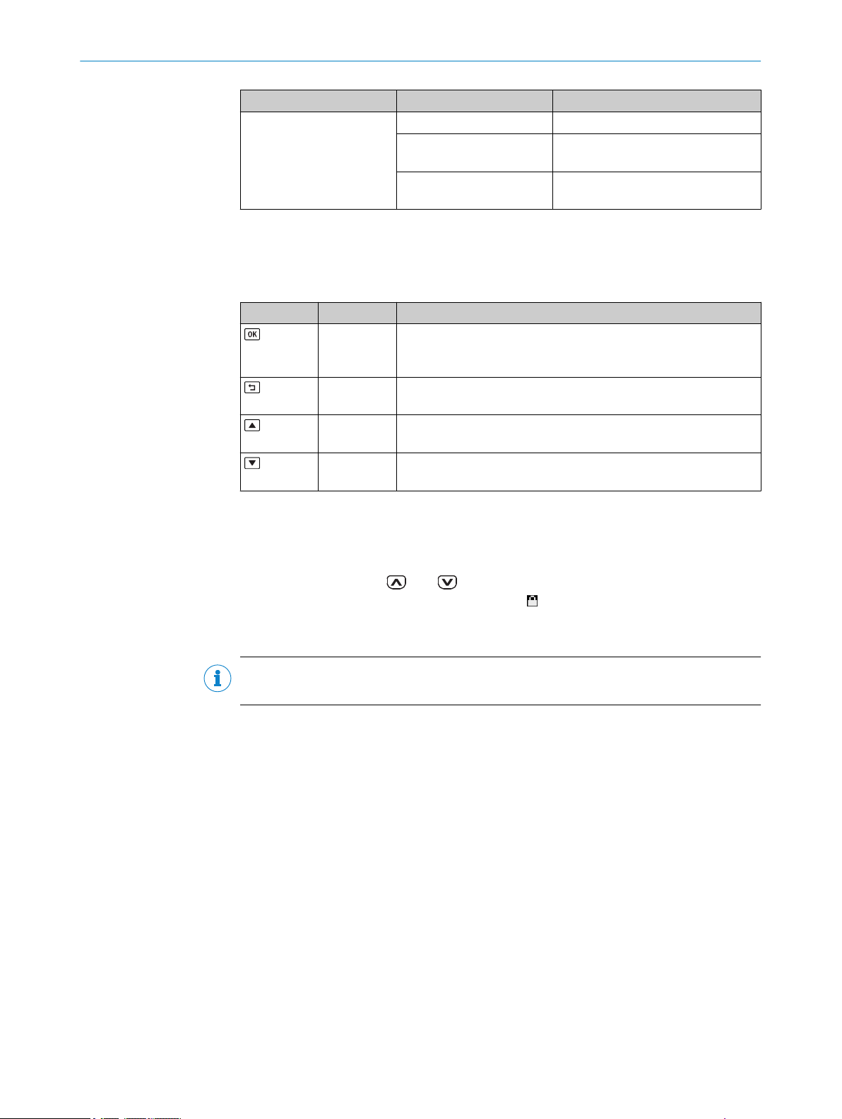
8.3.2.6 Action in case of incorrect measurements
If a distance measurement cannot be run, an error is output. Possible causes of the
error:
The measuring object is outside of the measuring range.
•
The light signal received by the device is not strong enough.
•
The laser is switched off.
•
You can configure the device behavior for the event that no measurement is possible.
The following options are available:
36
Substitute value in the event of an error: A numerical value can be entered which
•
is output when no measurement is possible.
Error mode > User-defined values: If no measurement is possible, the set Substi‐
•
tute value in the event of an error (see above) is displayed and held until a valid
measured value is available again.
Error mode > Hold last value: If no measurement is possible, the last valid meas‐
•
ured value is displayed and held until a valid measured value is available again.
O PE R AT I NG IN S TR U CT I ON S | OD1000 8019642/ZJW1/2017-04-03 | SICK
Subject to change without notice
Page 37
OPERATION VIA DISPLAY 8
Error mode > Hold last value for a defined time: If no measurement is possible,
•
the last valid measured value is displayed and held for the time set under Error
suppression time (see below). Once this time has elapsed, the set Substitute
value in the event of an error (see above) is displayed and held until a valid meas‐
ured value is available again.
Error suppression time: It is possible to set a time for which the last valid meas‐
•
ured value is displayed and held if the error mode Hold last value for a defined
time (see above) is activated.
> Measurement > > Default settings > > Action in case of incorrect measurements >
Parameter Factory setting
Substitute value in the event of an error:
-3,276.8 m ... +3,276.7 m
Error mode:
User-defined values
Hold last value
Hold last value for a defined time
Error suppression time:
0001 ms ... 9,999 ms
+3,276.7 m
✓
-
-
1 ms
8.4 I/O interface
8.4.1 Q1 output
The Q1 output is purely a switching output. In addition, the output serves as a commu‐
nication line for bidirectional data transmission when using the IO-Link interface.
The Q1 output of the OD 1000 provides the following switching modes:
DtO, distance to object (1-point), one switching point
•
Window, two switching points
•
ObSB, object between sensor (device) and background, one switching point
•
Alarm (only in Advanced user level)
•
Signal level warning (only in Advanced user level)
•
Edge height change (only in Advanced user level)
•
The switching modes are explained in the subsequent chapters.
8.4.1.1 Notes on the measuring and setting functions
The following functions can be set independently from each other on both outputs
depending on the selected output function.
Delay mode
Delay mode is used to output the output state change with a time delay or as a short
switching pulse (1 shot).
8019642/ZJW1/2017-04-03 | SICK OP E RA T IN G I N ST R UC T IO N S | OD1000
Subject to change without notice
37
Page 38

1 2 3
0,5 s
4
0,5 s
t
5
0,5 s0,5 s
High
Low
8 OPERATION VIA DISPLAY
1
2
3
4
5
Off: Right after the measured distance has exceeded the specified switching point, the
state of the switching output changes (factory setting).
Switch-on delay: The changeover of the switching output from an inactive to an active state
is time-delayed. The delay time is adjustable. The changeover from an active to an inac‐
tive state is not delayed.
Switch-off delay: The changeover of the switching output from an active to an inactive state
is time-delayed. The delay time is adjustable. The changeover from an inactive to an
active state is not delayed.
Switch-on/switch-off delay: The changeover from an inactive to an active state and vice
versa is time-delayed. The delay time is adjustable.
1 shot: Once the switching condition has been met, the switching output changes from an
inactive to an active state. The output state remains in an active state for a specified
period regardless of how long the switching condition is met. It does not switch back to an
inactive state until this time has elapsed. Any additional changes made to the switching
condition during this period are still not taken into account.
NOTE
For a combination of switch-on delay and switch-off delay, the following conditions
must be met:
Equidistant measuring frequency
•
Min. 2x measuring frequency
•
Cycle time must not be set to AUTO.
•
Active status
The active status describes the relationship between the output state (active or inac‐
tive) and the potential present on the switching output (high or low).
> I/O interface > > Q1 output > > Distance to object >
If the Distance to object switching mode is selected, the required settings can be taught
in or set manually. These are described in the following.
8.4.1.2 Distance to object, DtO, single switching point
A signal is output if the measured distance value has undershot (normally open – High
Active) or exceeded (normally closed – Low Active) the switching point.
38
O PE R AT I NG IN S TR U CT I ON S | OD1000 8019642/ZJW1/2017-04-03 | SICK
Subject to change without notice
Page 39

Min Max
1
1
0
Min Max
1
1
0
OPERATION VIA DISPLAY 8
Figure 13: Distance to object or single switching point (normally open – High Active, PNP)
Switching point
1
Figure 14: Distance to object or inverted single switching point (normally closed – Low Active,
PNP)
Switching point
1
If the “Distance to object” switching mode is selected, the required settings can be
taught in or set manually.
In the “Distance to object” operating mode, the following settings can be configured:
Teach-in
•
Manual teach-in
•
Active status
•
Hysteresis
•
Delay mode
•
Time for delay mode
•
The possible settings are described below.
Teach-in: A single switching point can be taught in. The switching point is set to the cur‐
rent distance at the time the button is pressed.
Q1: A signal is output if the switching point that has been taught in is undershot.
•
Thus the output acts as a normally open contact (“High” active status).
Q1not: A signal is output if the switching point that has been taught in is
•
exceeded. Thus the output acts as a normally closed contact (“Low” active status).
Manual teach-in: The distance of the switching point can be set manually in 1/10 mm.
Q1 active status: The active status specifies the functionality of the switching output, see
"Notes on the measuring and setting functions", page 37.
High: The switching output acts as a normally open contact. A signal is output if
•
the switching point that has been taught in is undershot.
Low: The switching output acts as a normally closed contact. A signal is output if
•
the switching point that has been taught in is exceeded.
Delay mode
see "Notes on the measuring and setting functions", page 37 .
•
Time for delay mode
The time for the delay mode can be set manually in ms.
•
I/O interface > > Q1 output > > Distance to object >
>
8019642/ZJW1/2017-04-03 | SICK OP E RA T IN G I N ST R UC T IO N S | OD1000
Subject to change without notice
39
Page 40

Min Max
1
1
0
2
Min Max
1
1
0
2
8 OPERATION VIA DISPLAY
Parameter Factory setting
Q1 teach-in:
Q1, Q1 not
Manual Q1 teach-in:
-1,000.0 mm ... +1,000.0 mm
Q1 active status:
High, Low
Q1 hysteresis:
0000.0 mm ... +0100.0 mm
Delay mode:
Off
Switch-on delay
Switch-off delay
Switch-on/switch-off delay
1 shot
Time for delay mode:
0000 ms ... 9,999 ms
8.4.1.3 Window
-
+400 mm
High
+1.0 mm
✓
-
-
-
-
100 ms
Window mode: An upper and a lower switching threshold are set for the switching out‐
put. A switching signal is output when the measured value is between the two switching
thresholds (in the window).
Figure 15: Normally open switching window (High Active, PNP)
Switching point near
1
Switching point far
2
Figure 16: Normally closed switching window (Low Active, PNP)
Switching point near
1
Switching point far
2
> I/O interface > > Q1 output > > Window >
Parameter Factory settings
Q1 teach-in:
Switching point 1, switching point 2
40
O PE R AT I NG IN S TR U CT I ON S | OD1000 8019642/ZJW1/2017-04-03 | SICK
-
Subject to change without notice
Page 41
Parameter Factory settings
Min Max
1
1
0
2
Min Max
1
1
0
2
Manual Q1 teach-in:
Switching point 1: -1,000.0 mm ... +1,000.0 mm
Switching point 2: -1,000.0 mm ... +1,000.0 mm
Q1 active status:
High, Low
Q1 hysteresis:
0000.0 mm ... +0100.0 mm +1.0 mm
Delay mode:
Off
Switch-on delay
Switch-off delay
Switch-on/switch-off delay
1 shot
Time for delay mode:
0 ms ... 9,999 ms
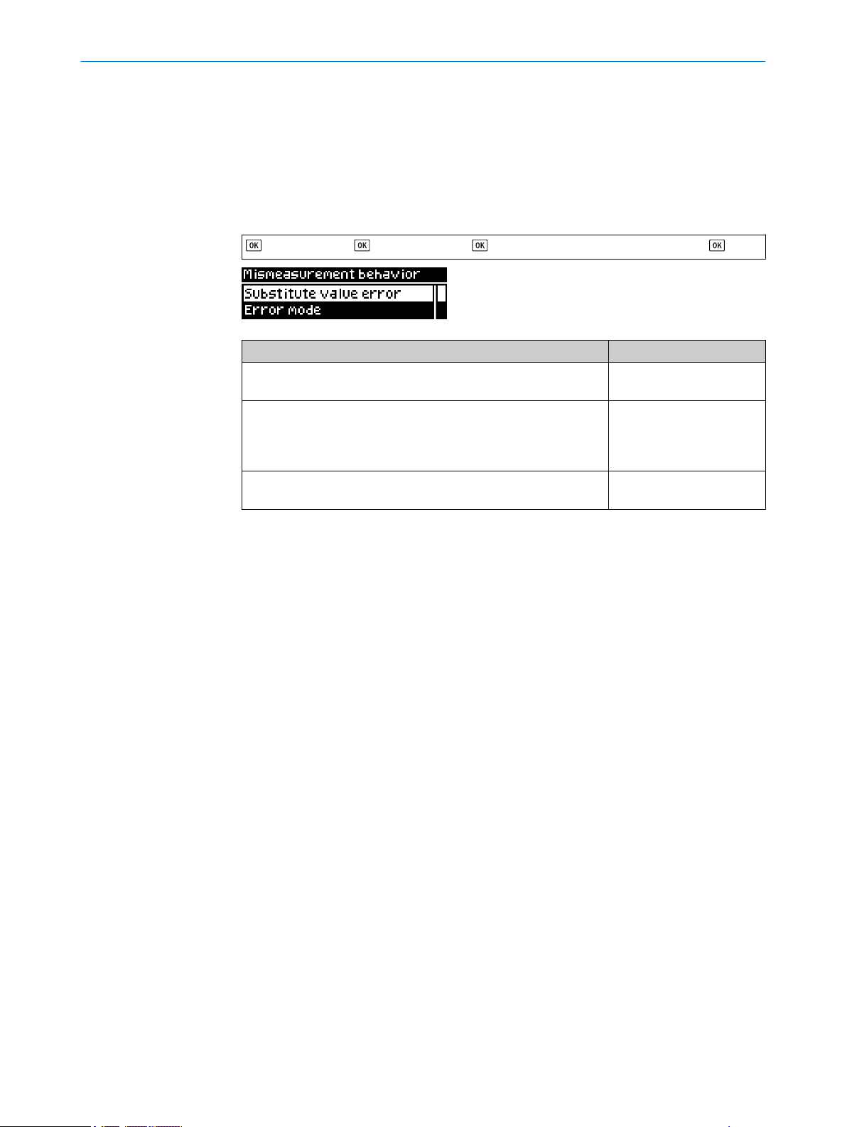
8.4.1.4 ObSB (object between sensor and background)
Object between device and background: In this switching mode, any background can be
taught in as a reference. If an object obscures the background or the distance to the
background changes significantly, this causes the device to switch. This switching mode
is primarily suited to the reliable detection of high-gloss or extremely dark materials.
This makes it possible to detect even painted vehicle parts with large approach angles,
for example.
OPERATION VIA DISPLAY 8
+400.0 mm
-400.0 mm
High
✓
-
-
-
-
100 ms
Figure 17: Object between device and background (normally open – High Active, PNP)
Switching point (reference background)
1
Tolerance around teach point: ± 4.0 mm
2
Figure 18: Object between device and background (normally closed – Low Active, PNP)
Switching point (reference background)
1
Tolerance around switching point: ± 4.0 mm
2
> I/O interface > > Q1 output > > ObSB >
8019642/ZJW1/2017-04-03 | SICK OP E RA T IN G I N ST R UC T IO N S | OD1000
Subject to change without notice
41
Page 42

8 OPERATION VIA DISPLAY
Parameter Factory setting
Q1 teach-in:
Q1, Q1 not
Manual Q1 teach-in:
-1,000.0 mm ... +1,000.0 mm
Q1 active status:
High, Low
Q1 hysteresis:
0000.0 mm ... +0100.0 mm
Q1 ObSB tolerance
-1,000.0 mm ... +1,000.0 mm
Delay mode:
Off, switch-on delay, switch-off delay, switch-on/switch-off delay, 1
shot
Time for delay mode:
0000 ms ... 9,999 ms
8.4.1.5 Alarm
The alarm function is only available in the Advanced user level. A constant switching sig‐
nal is output at the output of the device while no measurement is possible. This func‐
tion can be used to evaluate the measured value at the analog output, for example.
-
+400 mm
High
+1.0 mm
+4.0 mm
Off
100 ms
> I/O interface > > Q1 output > > Alarm >
Parameter Factory settings
Alarm Off
8.4.1.6 Signal level warning
The signal level warning function is only available in the Advanced user level.
A warning can be output via the Q1 and Q2 switching outputs if the signal level drops
below a certain value. This value can either be specified as a number value or deter‐
mined by the Teach-in function. When the Teach-in function is used, the threshold value
for outputting the warning is calculated by reducing the measured signal level value by
about 12%. Then the warning will not be output until the signal level is about 12% lower
than it was at the time it was taught in.
The level warning threshold or signal level switching point can be set manually using a
signal level within the value range of 0 to 5,000. The signal level is a sensor-specific,
unitless value. We recommend configuring the setting using application-specific test
measurements.
In automatic mode, the device automatically regulates the reception level to around
1000. In the case of very critical object surfaces, an abrupt loss of signal can therefore
occur as soon as a readjustment is no longer possible. In settings other than Auto, there
is no automatic adjustment, which makes it easier to define thresholds for the signal
level warning.
42
> I/O interface >
O PE R AT I NG IN S TR U CT I ON S | OD1000 8019642/ZJW1/2017-04-03 | SICK
> Q1 output > > Signal level warning >
Subject to change without notice
Page 43

OPERATION VIA DISPLAY 8
Parameter Factory settings
Q1 teach-in:
Switching point 1, switching point 2
Manual Q1 teach-in:
-0 ... 5,000
Q1 active status:
High, Low
Q1 hysteresis:
0 ... 10,000
Delay mode:
Off, switch-on delay, switch-off delay, switch-on/switch-off delay, 1
shot
Time for delay mode:
0000 ms ... 9,999 ms
-
112
High
10
Off
100 ms
8.4.1.7 Edge height change
The edge height change function is only available in the Advanced user level, see
"Device", page 51.
> I/O interface > > Q1 output > > Edge height change >
Parameter Factory settings
Q1 active status:
High, Low High
Delay mode:
Off, switch-on delay, switch-off delay, switch-on/switch-off delay, 1
shot
Time for delay mode:
0000 ms ... 9,999 ms 100 ms
8.4.2 Q2/Qa output
The output Q2/Qa can be configured either as an analog output or a switching output.
8.4.2.1 Notes on the output functions
Off
8.4.2.1.1 4-20 mA output function
If the 4-20 mA setting is selected, output 2 functions as an analog current output. The
measured value of the device is output as a proportional-linear current value that corre‐
sponds to the other device settings.
8019642/ZJW1/2017-04-03 | SICK OP E RA T IN G I N ST R UC T IO N S | OD1000
Subject to change without notice
43
Page 44

8 OPERATION VIA DISPLAY
8.4.2.1.2 0-10 V output function
If the 0-10 V setting is selected, output 2 functions as an analog voltage output. The
measured value of the device is output as a proportional-linear voltage value that corre‐
sponds to the other device settings.
8.4.2.1.3 Digital output function
In the case of the digital output function, output 2 functions as a switching output.
Since output 1 is used exclusively for switching, this setting corresponds to the behavior
of output 1. A switching signal that corresponds to the other device settings is output
based on the current measured value.
8.4.2.1.4 Off output function
When the Off output function is activated, output 2 does not have any function and is
therefore deactivated.
8.4.2.2 4-20 mA analog output
> I/O interface > > Q2/Qa output > > 4-20 mA analog output >
Parameter Factory setting
Qa teach-in:
Distance (4 mA)
Distance (20 mA)
Manual Qa teach-in:
Distance (4 mA): -1,000.0 mm ... +1,000.0 mm
Distance (20 mA): -1,000.0 mm ... +1,000.0 mm
8.4.2.3 0-10 V analog output
> I/O interface > > Q2/Qa output > > 0-10 V analog output >
Parameter Factory setting
Qa teach-in:
Distance (0 V)
Distance (10 V)
Manual Qa teach-in:
Distance (0 V): -1,000.0 mm ... +1,000.0 mm
Distance (10 V): -1,000.0 mm ... +1,000.0 mm
-
-
-400.0 mm
+400.0 mm
-
-
-400.0 mm
+400.0 mm
8.4.2.4 Digital output
44
O PE R AT I NG IN S TR U CT I ON S | OD1000 8019642/ZJW1/2017-04-03 | SICK
The Q2 digital output provides the following switching modes:
DtO, distance to object (1-point), one switching point
•
Window, two switching points
•
ObSB, object between sensor (device) and background, one switching point
•
Q2 = Q1 not
•
Subject to change without notice
Page 45

OPERATION VIA DISPLAY 8
Alarm (only in Advanced user level)
•
Signal level warning (only in Advanced user level)
•
Edge height change (only in Advanced user level)
•
> I/O interface > > Q2/Qa output > > Digital output >
Parameter Factory setting
Distance to object > Q2 teach-in:
Q2, Q2 not
Distance to object > manual Q2 teach-in:
-1,000.0 mm ... +1,000.0 mm
Distance to object > Q2 active status:
High, Low
Distance to object > Q2 hysteresis:
0000.0 mm ... +0100.0 mm
Distance to object > delay mode:
Off, switch-on delay, switch-off delay, switch-on/switch-off delay, 1
shot
Distance to object > time for delay mode:
0000 ms ... 9,999 ms
Window > Q2 teach-in:
Switching point 1, switching point 2
Window > manual Q2 teach-in:
Switching point 1, switching point 2
Window > Q2 active status:
High, Low
Window > Q2 hysteresis:
0000.0 mm ... +0100.0 mm
Window > delay mode:
Off, switch-on delay, switch-off delay, switch-on/switch-off delay, 1
shot
Window > time for delay mode:
0000 ms ... 9,999 ms
ObSB > Q2 teach-in:
Q2, Q2 not
ObSB > manual Q2 teach-in:
-1,000.0 mm ... +1,000.0 mm
ObSB > Q2 active status:
High, Low
ObSB > Q2 hysteresis:
0000.0 mm ... +0100.0 mm
ObSB > Q2 ObSB tolerance
-1,000.0 mm ... +1,000.0 mm
ObSB > delay mode:
Off, switch-on delay, switch-off delay, switch-on/switch-off delay, 1
shot
ObSB > time for delay mode:
0000 ms ... 9,999 ms
-
+400.0 mm
High
+1.0 mm
Off
100 ms
-
-
High
+1.0 mm
Off
100 ms
-
+400.0 mm
High
+1.0 mm
+4.0 mm
Off
100 ms
8019642/ZJW1/2017-04-03 | SICK OP E RA T IN G I N ST R UC T IO N S | OD1000
Subject to change without notice
45
Page 46

ON
OFF
1
2
HOLD
8 OPERATION VIA DISPLAY
8.4.2.5 Off
When the Off output function is activated, output 2 does not have any function and is
therefore deactivated.
8.4.3 In1 input
8.4.3.1 Notes on the input functions
8.4.3.1.1 Description
The In1 input is used for the following tasks:
■
Configuration of various device parameters, see "Teach-in", page 48
■
Switching the laser on or off at defined times
If the function is set to Teach (factory setting), the specific parameters or different meas‐
ured value hold functions can be configured by creating signal levels of different
lengths at pin 5. If the function is set to Laser off, when a signal is created the laser is
switched off for the duration of the created signal.
The In1 input must be active in order to be used accordingly (every setting apart from
Off). The Off setting deactivates the input and, therefore, all functions.
NOTE
Deactivating the input is possible only via the display, SOPAS ET, or IO-Link, but not via
the input itself.
The input behavior can be selected as normally open (High Active, factory setting) or
normally closed (Low Active). When Laser off is used, the logic also determines whether
the creation of a signal at the input causes the laser to switch off (factory setting) or on.
8.4.3.1.2 Hold function
The following hold functions are available:
•
Measured value: Holds the measured value which is present when there is a hold
input signal (rising edge).
Measured value
1
Output hold value (sample hold value)
2
46
Peak value: Holds the largest measured value which is present in the interval
•
between the last falling edge and the hold input signal (next rising edge).
O PE R AT I NG IN S TR U CT I ON S | OD1000 8019642/ZJW1/2017-04-03 | SICK
Subject to change without notice
Page 47

ON
OFF
1
2
3
HOLD
ON
OFF
1
2
3 3
HOLD
P(2)
P(1)
B(1)
B(2)
P(1)-B(1)
P(2)-B(2)
ON
OFF
1
3
2
3
HOLD
ON
OFF
1
2
3
HOLD
OPERATION VIA DISPLAY 8
Measured value
1
Output hold value (peak hold value)
2
Interval in which an analysis is carried out
3
Lowest value: Holds the smallest measured value which is present in the interval
•
between the last falling edge and the hold input signal (next rising edge).
Measured value
1
Output hold value (bottom hold value)
2
Interval in which an analysis is carried out
3
Peak-to-peak value: Holds the differential value between the smallest and the larg‐
•
est measured value present in the interval between the last falling edge and the
hold input signal (next rising edge).
Measured value
1
Output hold value (peak-to-peak hold value)
2
Interval in which an analysis is carried out
3
Average value: Holds the mathematical average of all measured values present in
•
the interval between the last falling edge and the hold input signal (next rising
edge).
Measured value
8019642/ZJW1/2017-04-03 | SICK OP E RA T IN G I N ST R UC T IO N S | OD1000
Subject to change without notice
1
2
3
Output hold value (average hold value)
Interval in which an analysis is carried out
47
Page 48

8 OPERATION VIA DISPLAY
8.4.3.1.3 Teach-in
Description
In the Teach-in operating mode you can use various teach functions by creating signal
levels of various lengths at the In1 input.
The timing tolerance for all teach functions is +/- 20 ms.
The following functions are available:
Teach function Time [ms]
Switching off laser 200
Switching on laser 300
Distance to object for Q1: Teach Q 400
Distance to object for Q1: Teach Q not 500
Switching window for Q1: Teach Q near 600
Switching window for Q1: Teach Q far 700
ObSB (Background) for Q1: Teach Q 800
ObSB (Background) for Q1: Teach Q not 900
Switching window for Q1: Centering teach 1000
Distance to object for Q2: Teach Q 1100
Distance to object for Q2: Teach Q not 1200
Switching window for Q2: Teach Q near 1300
Switching window for Q2: Teach Q far 1400
ObSB (Background) for Q2: Teach Q 1500
ObSB (Background) for Q2: Teach Q not 1600
Switching window for Q2: Centering teach 1700
QA with 4-20 mA for Q2: Teach 4 mA 1800
QA with 4-20 mA for Q2: Teach 20 mA 1900
QA with 0-10 V for Q2: Teach 0 V 2000
QA with 0-10 V for Q2: Teach 10 V 2100
QA (4-20 mA or 0-10 V): Centering teach 2200
Switching off teach confirmation 2300
Switching on teach confirmation 2400
Signal level warning Q1: Teach Q 2500
Signal level warning Q1: Teach Q not 2600
Signal level warning Q2: Teach Q 2700
Signal level warning Q2: Teach Q not 2800
Teaching in the zero point 2900
Laser off > 5,000
1
Centering limits. The near and far points that have been moved via centering must always lie within the
value range limits. Moved points must always be evaluated by the user.
8.4.3.2 In1 function
48
O PE R AT I NG IN S TR U CT I ON S | OD1000 8019642/ZJW1/2017-04-03 | SICK
Various device parameters can be configured, the laser can be switched on or off at
defined times, and device functions can be activated. The debounce function can be
activated or deactivated.
Subject to change without notice
Page 49

OPERATION VIA DISPLAY 8
> I/O interface > > In1 input > > In1 function >
Parameter Factory setting
Teach-in
Hold function -
Measured value offset -
Laser off -
Off -
Debouncing
The debounce function is only available in the Advanced user level.
When debouncing is activated, the input signal must be applied constantly to input In1
for 30 ms. The timing tolerances of the external teach-in functions take into account an
activation or deactivation of the debounce function. It is not necessary to adjust the
timings.
✓
> I/O interface > > In1 input > > In1 function > > Debouncing>
Parameter Factory setting
Debouncing?:
Yes, no Yes
8.4.3.3 In1 active status
The input behavior can be selected as normally open (High Active, factory setting) or
normally closed (Low Active).
Parameter Factory setting
High, Low High
> I/O interface > > In1 input > > In1 active status >
8.4.3.4 Teach confirmation
If the function is activated, a confirmation can be output via the switching output Q1 for
each teach-in via the In1 input.
8019642/ZJW1/2017-04-03 | SICK OP E RA T IN G I N ST R UC T IO N S | OD1000
Subject to change without notice
49
Page 50

max.
1 s
500 ms
In1 input
Hold (last active
Q1 status is held)
Teach-in successful
Teach-in failed
1 2 3 4 5 6 7
Teach-in successful
Teach-in failed
100 ms (OK)
100 ms (OK)
300 ms
(error)
300 ms
(error)
8 OPERATION VIA DISPLAY
Figure 19: Teach confirmation
Switching output before teach
1
Teach request retains the last active Q1 status in order, for example, to avoid toggling if
2
hysteresis is too low
Teach execution time, max. 1 s
3
First signal edge at Q1 after starting the teach: Initiate confirmation by inverting for
4
100 ms.
Result: OK (100 ms), error (300 ms)
5
Quit confirmation after 500 ms.
6
Return to current switching output. The switching output can be modified via a new teach
7
point.
> I/O interface > > In1 input > > Teach confirmation >
50
O PE R AT I NG IN S TR U CT I ON S | OD1000 8019642/ZJW1/2017-04-03 | SICK
Subject to change without notice
Page 51

8.5 Device
8.5.1 User level
OPERATION VIA DISPLAY 8
Parameter Factory setting
Yes, no No
Easy / Advanced
Only certain functions are available depending on the user level set:
Easy: frequently required functions (factory setting)
•
Advanced: virtually all available functions
•
Changing the user level only affects operation via display and via SOPAS ET. All func‐
tions can always be used for operation and configuration via IO-Link.
> Device > > User level >
8.5.2 Reset
Parameter Factory setting
Easy, Advanced Easy
The device can be reset to the factory settings or to saved customer settings (see "Saving
customer settings", page 51).
NOTE
Upon confirmation that the device is to be reset, it carries out a warm start. During the
device restarting process, the device and its function are temporarily deactivated.
> Device > > Reset > > Factory settings >
> Device > > Reset > > Customer settings >
Parameter Factory setting
Yes, no -
8.5.3 Saving customer settings
Once settings have been made, they can be saved as customer settings. These settings
can be restored at any time via Reset> Customer settings.
> Device > > Save customer settings >
8019642/ZJW1/2017-04-03 | SICK OP E RA T IN G I N ST R UC T IO N S | OD1000
Subject to change without notice
51
Page 52

8 OPERATION VIA DISPLAY
Parameter Factory setting
No, yes -
8.5.4 Language
The language of the display texts can be set.
> Device > > Language >
Parameter Factory setting
Deutsch/German, Englisch/English Englisch/English
8.5.5 Display settings
Settings can be made for the alignment, brightness, and switch-on/switch-off behavior
of the display.
Description of the parameters for the switch display on/off function:
Auto: The display switches itself off if no buttons are pressed for 3 minutes. The
•
display switches on again when a button is pressed.
Off: The display switches itself off when the button lock is activated. If the button
•
lock is not activated, the display switches itself off if no buttons are pressed for 3
minutes. The display switches on again when a button is pressed.
On: The display remains permanently on (not recommended, reduces the service
•
life of the OLED display).
> Device > > Display settings >
Parameter Factory setting
Switch display on/off:
Auto, off, on
Display brightness:
0% ... 100%
Display alignment:
0°, 180°
Auto
50%
0°
8.5.6 Measurement laser
The measurement laser can be switched off. No measurement is possible when the
laser is switched off.
NOTE
The laser can also be switched on/off via the In1 input.
52
O PE R AT I NG IN S TR U CT I ON S | OD1000 8019642/ZJW1/2017-04-03 | SICK
Subject to change without notice
Page 53

> Device > > Measurement laser >
Parameter Factory setting
Off, on On
8.6 Communication
I/O-Link COM selection
The IO-Link communication mode of the device can be set. Associated IODD device
description files are available on the website, see www.sick.com/OD1000.
> Communication
OPERATION VIA DISPLAY 8
Parameter Factory setting
COM2, COM3 COM3
8.7 Info
Various types of status information are displayed for the device.
8.7.1 Firmware verification
The firmware version of the device is displayed.
> Info > > Firmware verification >
8.7.2 Serial number
The serial number of the device is displayed.
> Info > > Serial number >
8.7.3 Sensor operating hours
The operating hours of the device are displayed.
> Info > > Sensor operating hours >
8019642/ZJW1/2017-04-03 | SICK OP E RA T IN G I N ST R UC T IO N S | OD1000
Subject to change without notice
53
Page 54

8 OPERATION VIA DISPLAY
8.7.4 Laser operating hours
The operating hours of the laser are displayed.
> Info > > Laser operating hours >
8.7.5 Sensor status
Information about the status of the device is displayed.
The following data can be accessed:
Number of errors: States the number of errors that have occurred
•
Number of warnings: States the number of active warnings
•
Error history: Detailed information and history of the most recent errors (max. 10)
•
> Info > > Sensor status >
8.7.6 Part number
Parameter Factory setting
Number of errors, number of warnings, error history -
The part number of the device is displayed.
> Info > > Part number >
54
O PE R AT I NG IN S TR U CT I ON S | OD1000 8019642/ZJW1/2017-04-03 | SICK
Subject to change without notice
Page 55

9 Operation via IO-Link
The device can exchange process data and parameters via IO-Link. To do this, it is con‐
nected to a suitable IO-Link master.
The IO-Link interface of the device has the following properties:
Table 5: Properties of the IO-Link interface
IO-Link specification V 1.1
Minimum cycle time 2.3 ms (COM2)
Transmission rate adjustable
Process data width 16-bit outgoing (from the device to the master)
Process data type INT (signed integer)
Parameter configuration server function (data
storage)
OPERATION VIA IO-LINK 9
V 1.0
0.46 ms (COM3)
COM2 (38.4 kBaud)
COM3 (230.4 kBaud)
Yes
9.1 Process data
In the factory settings, the process data telegram displays the distance value measured
by the device in millimeters (16-bit width unsigned).
By configuring the parameters of the device you can change the process data format as
well as resolution and offset for the distance value.
The following process data formats are available:
Table 6: Process data formats
9.2 Device data
In addition to the process data, device data (parameters, identification data, and diag‐
nostic information) can be transmitted to and from the device. To use this function, a
sensor-specific device description file (IODD) is needed in the IO-Link master.
No. Description Comments
1 Distance (16-bit) Factory setting
2 Level (16-bit) -
3 Timer (16-bit) -
4 Edge height change (16-bit) -
5 Distance (14-bit) + Status Q1 + Status Q
6 Level (14-bit) + Status Q1 + Status Q
7 Timer (14-bit) + Status Q1 + Status Q
8 Edge height change (14-bit) + Status Q1 + Status Q
2
2
2
2
-
-
-
-
A download package with the IODD and supplementary documentation is available at
www.sick.com/OD1000.
8019642/ZJW1/2017-04-03 | SICK OP E RA T IN G I N ST R UC T IO N S | OD1000
Subject to change without notice
55
Page 56

OPERATION VIA SOPAS ET
10
10 Operation via SOPAS ET
Version 3.3 and higher of the SOPAS Engineering Tool (SOPAS ET) software can be used
to configure the device and for service and diagnostic purposes.
The following are required to configure the device parameters using a computer:
– A computer with SOPAS ET installed and a free USB2.0-compatible port
– SICK SiLink2 Master (Order No. 1061790)
– Connection cable with M12 male and female connectors, 5-pin (e.g. Order No.
6025930)
Connect the device to the SiLink2 Master via the plug connection or an additional con‐
nection cable. Connect the SiLink2 Master to the PC using the USB cable provided and
also connect the wall plug provided to the SiLink2 Master in order to ensure a sufficient
voltage supply to the device.
NOTE
The most up-to-date version of the SOPAS ET software can be downloaded from
www.sick.com/SOPAS_ET. The respective system requirements for installing SOPAS ET
are also specified there.
NOTE
To use SOPAS ET with the device, you need a device description file (SDD) for this
device. You can install this within SOPAS ET using the device catalog. An Internet con‐
nection is required to install the SDD file.
Figure 20: SOPAS ET start screen – visualization of the distance values and the output state
56
O PE R AT I NG IN S TR U CT I ON S | OD1000 8019642/ZJW1/2017-04-03 | SICK
Subject to change without notice
Page 57

OPERATION VIA SOPAS ET
Figure 21: SOPAS ET function menus – visualization of the light distribution curve on the receiver
for easy setting of the distance range
10
NOTE
The device immediately applies parameters that have been modified using SOPAS ET
and permanently saves them. This does not require calling up a separate function.
As well as visualizing the measured values, all device functions can also be set and
checked in SOPAS ET. SOPAS ET is particularly useful for configuring the distance range
and edge height change functions, which are only available in the Advanced user level.
8019642/ZJW1/2017-04-03 | SICK OP E RA T IN G I N ST R UC T IO N S | OD1000
Subject to change without notice
57
Page 58

11 MAINTENANCE
11 Maintenance
11.1 Cleaning
NOTICE
Equipment damage due to improper cleaning.
Improper cleaning may result in equipment damage.
■
■
b
NOTE
Static charge may cause dust particles to stick to the inspection window. This effect can
be avoided by using an anti-static cleaning agent in combination with the SICK lens
cloth (can be obtained from www.sick.com).
Only use recommended cleaning agents.
Never use sharp objects for cleaning.
Clean the front screens at regular intervals and in the event of contamination with
a lint-free lens cloth (part no. 4003353) and plastic cleaning agent (part no.
5600006). The cleaning interval essentially depends on the ambient conditions.
Cleaning the housing
In order to ensure that heat is adequately dissipated from the device, the housing sur‐
face must be kept clean.
b
11.2 Maintenance
During operation, the device works maintenance-free.
Depending on the assignment location, the following preventive maintenance tasks
may be required for the device at regular intervals:
Table 7: Maintenance schedule
Clear the build up of dust on the housing with a soft brush.
Maintenance work Interval To be carried out
by
Clean housing and front screen Cleaning interval depends on ambi‐
ent conditions and climate
Check the screw connections and
plug connections
Every 6 months Specialist
Specialist
58
O PE R AT I NG IN S TR U CT I ON S | OD1000 8019642/ZJW1/2017-04-03 | SICK
Subject to change without notice
Page 59

12 Troubleshooting
Possible faults and rectification measures are described in the table below. In the case
of faults that cannot be rectified using the information below, please contact the manu‐
facturer. See the back page for your agency.
12.1 General faults, warnings, and errors
General faults are subdivided into warnings and errors. Current measured values con‐
tinue being output when there are warnings; measurement is no longer possible when
there are faults.
Table 8: Troubleshooting questions and replies
Question Reply
The device is not displaying
a measurement.
The display shows a warn‐
ing triangle in the top right.
Advanced application settings Check first whether the device laser is
activated and whether the laser light spot is pointing at the object.
Make sure that the object is within the measuring range of the
device. Check the light distribution curve in SOPAS ET. This func‐
tion is only available under the section in the user level. The light
distribution curve shows whether the receiver element of the
device is receiving light. In this case, the light distribution curve
normally displays a maximum within the area shown. This graphic
visualizes the remission of light onto the receiver element.
No measurement possible. Check the possible causes: Light path
obscured / device not in measuring range / reflective surface.
TROUBLESHOOTING 12
12.2 Detecting and displaying errors
In addition to measurement errors (see "Action in case of incorrect measurements",
page 36), the device can also detect and display other errors. These are output by the
display, Sopas ET, or IO-Link.
In addition to measurement errors, the device can also detect and display other errors.
These are output by Sopas ET, IO-Link, or via the software user interface.
Error memory
The device has an error memory where its internal error states are recorded. The last
error to have occurred is always saved. The content of the error memory is retained
when the device is switched off and when the Reset > Factory settings function is used.
Possible errors
Table 9: Explanation of the error codes
Error code SOPAS ET hex code /
device status
- - / No signal No measurement pos‐
- - / Laser switched off Laser is deactivated Activate laser
Temperature
error
0x50 / Temperature
error
0x10 / Temperature
warning
Meaning Countermeasure(s)
Check the measuring
sible
Operating temperature
undershot or
exceeded
range, increase the cycle
time setting, or reduce the
distance to the object.
Alternatively, contact the
technical support team of
the manufacturer
Check the ambient temper‐
ature and raise or lower it if
necessary
8019642/ZJW1/2017-04-03 | SICK OP E RA T IN G I N ST R UC T IO N S | OD1000
Subject to change without notice
59
Page 60

12 TROUBLESHOOTING
Error code SOPAS ET hex code /
device status
Laser error 0x11 / Laser warning
0x60 / Laser error 1
0x61 / Laser error 2
0x62 / Laser error 3
Internal error 0x80 / Internal error 1
0x81 / Internal error 2
0x82 / Internal error 3
0x83 / Internal error 4
If a different message is output, please contact the manufacturer's technical support.
12.3 Information for service cases
You should collect and write down the following device information ahead of time if you
need to contact the manufacturer's service department:
Information about the firmware version
•
Information about the hardware
•
Information about operating hours
•
This information can be accessed via SOPAS AIR.
Meaning Countermeasure(s)
Laser error Please contact the manu‐
facturer's technical support
Operating fault Check the electrical envi‐
ronment and improve it, if
necessary (stability, voltage
supply, EMC influences). If
the error cannot be recti‐
fied: Please contact the
manufacturer's technical
support.
12.4 Returns
12.5 Repairs
12.6 Disposal
Do not dispatch devices to the SICK service department without consultation.
•
NOTE
To enable efficient processing and allow us to determine the cause quickly, please
include the following when making a return:
■
Details of the contact person
■
Description of the application
■
Description of the fault that occurred
Repair work on the device may only be performed by qualified and authorized person‐
nel from SICK AG. Interruptions or modifications to the device by the customer will inva‐
lidate any warranty claims against SICK AG.
CAUTION
Risk of injury due to hot device surface.
The surface of the device can become hot during operation.
Before commencing disassembly, switch off the device and allow it to cool down
b
as necessary.
60
O PE R AT I NG IN S TR U CT I ON S | OD1000 8019642/ZJW1/2017-04-03 | SICK
Subject to change without notice
Page 61

TROUBLESHOOTING 12
Any device which can no longer be used at the end of the product life cycle must be
disposed of in an environmentally friendly manner in accordance with the respective
applicable country-specific waste disposal regulations. Do not dispose of the product
along with household waste.
NOTICE
Danger to the environment due to improper disposal of the device.
Disposing of devices improperly may cause damage to the environment.
Therefore, observe the following information:
Always observe the valid regulations on environmental protection.
b
Separate the recyclable materials by type and place them in recycling containers.
b
8019642/ZJW1/2017-04-03 | SICK OP E RA T IN G I N ST R UC T IO N S | OD1000
Subject to change without notice
61
Page 62

13 TECHNICAL DATA
13 Technical data
NOTE
The relevant online data sheet for your product can be downloaded, saved, and printed,
including technical data, dimensions, and connection diagrams:
www.sick.com/OD1000
b
13.1 Performance
Table 10: Technical data for performance
Measuring range 200 mm ... 1,000 mm
Resolution 50 µm
Reproducibility 0.4 mm
Linearity ± 1.5 mm
Response time 1.5 ms
Measuring frequency ≤ 3 kHz
Light sender Laser, red (visible, wavelength 655 nm, max. pulse output
Laser class 1 (EN 60825-1:2014)
Typical light spot size 1.5 mm x 1.5 mm
Additional function Adjustable averaging or median filter, switching mode: distance to
1
6% ... 90% remission, with standard settings
2
90% remission (white), with constant ambient conditions
3
Statistical error 3 σ
4
For optimum performance observe min. warm-up time of 10 minutes
5
With measuring frequency of 3 kHz, target change white 90%/white 90%
1
2
2, 3
2, 4
5
0.78 mW, max. average power 0.39 mW, max. pulse duration
1.8 ms)
object (DtO), window or ObSB (object between sensor (device) and
background), teachable switching output, invertible switching out‐
put, teachable analog output, invertible analog output, switchable
analog output mA/V, multifunctional input: laser off / external
teach-in / deactivated, display switch-off, user interface lock, dis‐
play can be rotated by 180°, alarm function, edge height change,
time functions (ON/OFF delay), 1-shot)
62
O PE R AT I NG IN S TR U CT I ON S | OD1000 8019642/ZJW1/2017-04-03 | SICK
Subject to change without notice
Page 63

Linearity
–3.0
(–0.04)
–2.0
(–
0.08
)
–1.0
(–
0.12
)
0.0
1.0
(
0.04
)
2.0
(
0.08
)
3.0
(0.12)
200
(7.87)
300
(11.81)
400
(15.75)
500
(19.69)
600
(23.62)
700
(27.56)
800
(31.50)
900
(35.43)
1000
(39.37)
Typical linearity deviation in mm (inch)
Distance in mm (inch)
White 90 % remission
1
Black 6 % remission
2
Stainless steel
3
2
1
3
TECHNICAL DATA 13
13.2
13.3 Mechanics/electronics
Interfaces
Figure 22: Linearity diagram
Table 11: Technical data for interfaces
Analog output
1x 4 mA ... 20 mA (< 600 W) / 1 x 0 V … 10 V (> 20 kW)
Resolution: 16-bit
Switching output 2 x push/pull 1, IO-Link
Multifunctional input (In1
1 x
2
input)
IO-Link Function: Process data, configuration, diagnostics, data storage
Data transmission rate: 230.4 kBit/s (COM3) / 38.4 kBit/s
(COM2)
Protocol: V 1.1 / V 1.0
1
PNP: HIGH = UV- (< 3 V) / LOW = < 3 V; NPN: HIGH = < 3 V / LOW = UV
2
Can be used as laser off, external teach-in, or deactivated
Table 12: Technical data for mechanics/electronics
Supply voltage U
v
Residual ripple ≤ 5 V
DC 18 V ... 30 V
2
ss
Power consumption ≤ 2.5 W
Warm-up time < 10 min
Housing material Zinc die cast acrylic glass (PMMA), with scratch-proof coating
1
3
8019642/ZJW1/2017-04-03 | SICK OP E RA T IN G I N ST R UC T IO N S | OD1000
Subject to change without notice
63
Page 64

13 TECHNICAL DATA
Connection type 20 cm cable with M12 male connector, 5-pin
Display OLED display, 3 status LEDs
Weight 280 g
Dimensions see "Setup and dimensions", page 12
Enclosure rating IP 65, IP 67
Protection class III in accordance with EN 50178
1
2
3
13.4 Ambient data
Table 13: Ambient data
Ambient operating temperature –10 °C … +50 °C
Storage temperature –20 °C … +60 °C
Temperature drift 0.15 mm/K
Typ. ambient light immunity Artificial light: ≤ 3,000 lx
Vibration resistance EN 60068-2-6 / EN 60068-2-64
Shock resistance EN 60068-2-27
1
2
Limit values, reverse-polarity protected. Operation in short-circuit protected network: max. 8 A.
May not fall short of or exceed Uv tolerances
Without load, at +20 °C
1
2
Sunlight: ≤ 10,000 lx
At UV = 24 V
With constant object movement in the measuring range
64
O PE R AT I NG IN S TR U CT I ON S | OD1000 8019642/ZJW1/2017-04-03 | SICK
Subject to change without notice
Page 65

14 Accessories
14.1 Accessories
NOTE
Accessories and where applicable mounting information can be found online at:
b
ACCESSORIES 14
www.sick.com/OD1000
8019642/ZJW1/2017-04-03 | SICK OP E RA T IN G I N ST R UC T IO N S | OD1000
Subject to change without notice
65
Page 66

15 ANNEX
15 Annex
15.1 EU declaration of conformity / Certificates
The EU declaration of conformity and other certificates can be downloaded from the
Internet at:
www.sick.com/OD1000
•
15.2 Licenses
SICK uses open-source software. This software is licensed by the rights holders using
the following licenses among others: the free licenses GNU General Public License (GPL
Version2, GPL Version3) and GNU Lesser General Public License (LGPL), the MIT
license, zLib license, and the licenses derived from the BSD license.
This program is provided for general use, but WITHOUT ANY WARRANTY OF ANY KIND.
This warranty disclaimer also extends to the implicit assurance of marketability or suita‐
bility of the program for a particular purpose.
More details can be found in the GNU General Public License. View the complete
license texts here: www.sick.com/licensetexts. Printed copies of the license texts are
also available on request.
66
O PE R AT I NG IN S TR U CT I ON S | OD1000 8019642/ZJW1/2017-04-03 | SICK
Subject to change without notice
Page 67

ANNEX 15
8019642/ZJW1/2017-04-03 | SICK OP E RA T IN G I N ST R UC T IO N S | OD1000
Subject to change without notice
67
Page 68

Australia
Phone +61 3 9457 0600
1800 334 802 – tollfree
E-Mail sales@sick.com.au
Austria
Phone +43 22 36 62 28 8-0
E-Mail office@sick.at
Belgium/Luxembourg
Phone +32 2 466 55 66
E-Mail info@sick.be
Brazil
Phone +55 11 3215-4900
E-Mail marketing@sick.com.br
Canada
Phone +1 905 771 14 44
E-Mail information@sick.com
Czech Republic
Phone +420 2 57 91 18 50
E-Mail sick@sick.cz
Chile
Phone +56 2 2274 7430
E-Mail info@schadler.com
China
Phone +86 20 2882 3600
E-Mail info.china@sick.net.cn
Denmark
Phone +45 45 82 64 00
E-Mail sick@sick.dk
Finland
Phone +358-9-2515 800
E-Mail sick@sick.fi
France
Phone +33 1 64 62 35 00
E-Mail info@sick.fr
Germany
Phone +49 211 5301-301
E-Mail info@sick.de
Hong Kong
Phone +852 2153 6300
E-Mail ghk@sick.com.hk
Hungary
Phone +36 1 371 2680
E-Mail office@sick.hu
India
Phone +91 22 4033 8333
E-Mail info@sick-india.com
Israel
Phone +972 4 6881000
E-Mail info@sick-sensors.com
Italy
Phone +39 02 274341
E-Mail info@sick.it
Japan
Phone +81 3 5309 2112
E-Mail support@sick.jp
Malaysia
Phone +6 03 8080 7425
E-Mail enquiry.my@sick.com
Mexico
Phone +52 472 748 9451
E-Mail mario.garcia@sick.com
Netherlands
Phone +31 30 2044 000
E-Mail info@sick.nl
New Zealand
Phone +64 9 415 0459
0800 222 278 – tollfree
E-Mail sales@sick.co.nz
Norway
Phone +47 67 81 50 00
E-Mail sick@sick.no
Poland
Phone +48 22 539 41 00
E-Mail info@sick.pl
Romania
Phone +40 356 171 120
E-Mail office@sick.ro
Russia
Phone +7 495 775 05 30
E-Mail info@sick.ru
Singapore
Phone +65 6744 3732
E-Mail sales.gsg@sick.com
Slovakia
Phone +421 482 901201
E-Mail mail@sick-sk.sk
Slovenia
Phone +386 591 788 49
E-Mail office@sick.si
South Africa
Phone +27 11 472 3733
E-Mail info@sickautomation.co.za
South Korea
Phone +82 2 786 6321
E-Mail info@sickkorea.net
Spain
Phone +34 93 480 31 00
E-Mail info@sick.es
Sweden
Phone +46 10 110 10 00
E-Mail info@sick.se
Switzerland
Phone +41 41 619 29 39
E-Mail contact@sick.ch
Taiwan
Phone +886 2 2375-6288
E-Mail sales@sick.com.tw
Thailand
Phone +66 2645 0009
E-Mail Ronnie.Lim@sick.com
Turkey
Phone +90 216 528 50 00
E-Mail info@sick.com.tr
United Arab Emirates
Phone +971 4 88 65 878
E-Mail info@sick.ae
United Kingdom
Phone +44 1727 831121
E-Mail info@sick.co.uk
USA
Phone +1 800 325 7425
E-Mail info@sick.com
Vietnam
Phone +84 945452999
E-Mail Ngo.Duy.Linh@sick.com
Further locations at www.sick.com
8019642/ZJW1/2017-04-03 | 8M_DR | en
SICK AG | Waldkirch | Germany | www.sick.com
 Loading...