

Page 1
NAV-LOC
Laser positioning system
O P E R A T I N G I N S T R U C T I O NS
Page 2

8021386/12G4 /2019-04-24 | SICK OPERATING INSTRUCTIONS | NAV-LOC
2
Subject to change without notice
Product described
NAV-LOC
Manufacturer
SICK AG
Erwin-Sick-Str. 1
79183 Waldkirch
Germany
Legal notes
This work is protected by copyright. The associated rights are reserved by SICK AG. Reproduction of this document
or parts of this document is only permissible within the limits of the legal provisions of copyright law. Any modification, abridgment, or translation of this document is prohibited without the express written permission of SICK AG.
The trademarks mentioned in this document are the property of their respective owners.
© SICK AG. All rights reserved.
Original document
This document is an original document of SICK AG.
Page 3

1 About this document
8021386/12G4 /2019-04-24 | SICK OPERATING INSTRUCTIONS | NAV-LOC
3
Subject to change without notice
Contents
1 About this document ................................................................................................................ 6
1.1 Information on the operating instructions ..................................................................................... 6
1.2 Explanation of symbols ..................................................................................................................... 6
1.3 Further information ........................................................................................................................... 7
1.4 Customer service ............................................................................................................................... 7
2 Safety information .................................................................................................................... 8
2.1 General safety notes ......................................................................................................................... 8
2.2 Hazard warnings and operational safety ....................................................................................... 8
2.3 Intended use ....................................................................................................................................... 8
2.4 Improper use ...................................................................................................................................... 8
2.5 IP technology ...................................................................................................................................... 9
2.6 Requirements for operating personnel .......................................................................................... 9
3 Product description ................................................................................................................ 10
3.1 Scope of delivery ............................................................................................................................. 10
3.2 Design and function of NAV-LOC .................................................................................................. 11
3.3 Sensor Integration Machine (SIM) ............................................................................................... 12
3.4 Measurement accuracy ................................................................................................................. 12
3.5 Telegram listing .............................................................................................................................. 12
3.6 Data interfaces................................................................................................................................ 12
3.7 Diagnosis.......................................................................................................................................... 12
3.7.1 Diagnostic via LED status indicators ................................................................................................ 13
3.7.2 Diagnostic via SOPAS AIR .................................................................................................................. 14
3.7.3 Diagnostic via telegram ..................................................................................................................... 15
3.8 Reference map ............................................................................................................................... 15
3.9 Dynamic Environment Handling ................................................................................................... 17
3.10 Initial position .................................................................................................................................. 17
3.10.1 X,Y (position uncertainty) ................................................................................................................... 17
3.10.2 Yaw (orientation uncertainty) ............................................................................................................ 17
3.10.3 Environment specific considerations ............................................................................................... 18
3.11 Output of position and additional information .......................................................................... 21
3.11.1 Pose quality .......................................................................................................................................... 21
3.11.2 Advanced options ................................................................................................................................ 22
4 System requirements of NAV-LOC........................................................................................ 24
4.1 Requirements for the environment ............................................................................................. 24
4.2 Requirements for the 2D LiDAR sensor ...................................................................................... 24
5 Operating modes of NAV-LOC ............................................................................................... 26
5.1 IDLE mode ....................................................................................................................................... 26
Page 4

1 About this document
8021386/12G4 /2019-04-24 | SICK OPERATING INSTRUCTIONS | NAV-LOC
4
Subject to change without notice
5.2 READY mode ................................................................................................................................... 26
5.3 PREPARE mode .............................................................................................................................. 27
5.4 LOCALIZE mode .............................................................................................................................. 27
6 Initial commissioning and demonstration mode............................................................... 28
6.1 Initial connection setup ................................................................................................................. 28
6.2 Creating a demo map .................................................................................................................... 29
7 Full Integration and commissioning .................................................................................... 31
7.1 Notes and preparatory information ............................................................................................. 31
7.2 Required software .......................................................................................................................... 32
7.3 Power supply ................................................................................................................................... 32
7.4 Network setup ................................................................................................................................. 33
7.4.1 SIM configuration ................................................................................................................................ 33
7.4.2 Connection setup ................................................................................................................................ 35
7.4.3 Switch usage ........................................................................................................................................ 36
7.4.4 Result port output ............................................................................................................................... 37
7.5 Transfering the reference map ..................................................................................................... 37
7.6 Configuration of the the embedded application ........................................................................ 38
7.6.1 Invoking SOPAS AIR via web browser .............................................................................................. 38
7.6.2 IDLE: Data source settings ................................................................................................................. 39
7.6.3 IDLE: Mounting Position (optional) ................................................................................................... 40
7.6.4 IDLE: Scan filter (optional) ................................................................................................................. 41
7.6.5 READY: Settings for localization ....................................................................................................... 43
7.6.6 LOCALIZE: Indication of contour and position ................................................................................ 45
7.6.7 LOCALIZE: Settings for the result port (data output) ..................................................................... 46
8 Synchronization ....................................................................................................................... 49
8.1 Synchronization options ................................................................................................................ 49
8.1.1 Synchronization via telegram request (polling) .............................................................................. 49
8.1.2 Synchronization via telegram request (polling) and HW port ...................................................... 50
8.1.3 Synchronization via a cyclical pulse provided on HW port ........................................................... 51
8.2 Setting of the hardware outputs .................................................................................................. 52
9 Troubleshooting ...................................................................................................................... 54
9.1 Hints to the network connection .................................................................................................. 54
9.2 Hints to initialization ...................................................................................................................... 54
9.3 Localization hints ............................................................................................................................ 55
9.3.1 Localization does not start ................................................................................................................ 55
9.3.2 No localization data is output ........................................................................................................... 55
9.3.3 Characters ............................................................................................................................................ 55
10 Transport and storage ............................................................................................................ 56
10.1 Transport .......................................................................................................................................... 56
10.2 Transport inspection ....................................................................................................................... 56
Page 5

1 About this document
8021386/12G4 /2019-04-24 | SICK OPERATING INSTRUCTIONS | NAV-LOC
5
Subject to change without notice
10.3 Storage ............................................................................................................................................. 56
11 Service and maintenance ...................................................................................................... 57
12 NAV-LOC data sheet ............................................................................................................... 58
12.1 NAV-LOC features ........................................................................................................................... 58
12.2 System latencies............................................................................................................................. 59
Page 6
1 About this document
8021386/12G4 /2019-04-24 | SICK OPERATING INSTRUCTIONS | NAV-LOC
6
Subject to change without notice
1 About this document
1.1 Information on the operating instructions
These operating instructions are intended to allow the technical personnel to perform safe mounting,
electrical installation work, configuration, commissioning, and maintenance on the 2D LiDAR sensor
and the “Sensor Integration Machine” (SIM) for localization based on contour data. The SIM20000A20A00 and a 2D LiDAR sensor are used together and referred to as NAV-LOC in the following description. The system components are referred to as 2D LiDAR sensor and SIM (Sensor Integration
Machine) for short, unless a clear distinction needs to be made.
This document describes solely how to operate NAV-LOC in a general sense. The instructions stated
below are supplementary device-specific documents for 2D LiDAR sensors, which can be combined
with the SIM2000-0A20A00 as a data source. These are required in addition as they describe the
specific connection options and configuration for each sensor:
NAV-LOC: SIM2000, NAV310 operating instructions (German 8023449, English 8023450)
NAV-LOC: SIM2000, NAV245 operating instructions (German 8023451, English 8023452)
NAV-LOC: Telegram Listing (English 8021387)
1.2 Explanation of symbols
All symbols used in this document and their meaning, warnings, and important information are marked
with symbols in this document and are compiled below. The warnings are introduced by signal words
that indicate the extent of the danger. These warnings must be observed at all times and care must be
taken to avoid accidents, personal injury, and material damage.
DANGER
… indicates a situation of imminent danger, which will lead to a fatality or serious
injuries if not prevented.
WARNING
… indicates a situation of possible danger, which can lead to a fatality or serious
injuries if not prevented.
CAUTON
… indicates a situation of possible danger, which can lead to minor or moderate
injuries if not prevented.
IMPORTANT
… indicates a situation, which can lead to property damage
if not prevented.
NOTE
… highlights useful tips and recommendations as well as information for efficient
and trouble-free operation.
Page 7

1 About this document
8021386/12G4 /2019-04-24 | SICK OPERATING INSTRUCTIONS | NAV-LOC
7
Subject to change without notice
1.3 Further information
NOTE
All the documentation available for the device can be found on the online product page at:
www.sick.com
Solely type the specific document or device number in the search field.
This document describes solely how to operate NAV-LOC in a general sense. The instructions stated
below are supplementary device-specific documents for 2D LiDAR sensors, which can be combined
with the SIM2000-0A20A00 as a data source. These are required in addition as they describe the
specific connection options and configuration for each sensor. The following information is available
for download from this page:
• NAV-LOC variants:
o NAV-LOC: SIM2000, NAV310 operating instructions (German 8023449, English
8023450)
o NAV-LOC: SIM2000, NAV245 operating instructions (German 8023451, English
8023452)
• Model-specific online data sheets for device variants, containing technical data, dimensional draw-
ings and diagrams e.g.:
o Operating instructions of the SIM2000 (German 8020763, English 8020764)
o Operating instructions of the NAV310 (German 8016534, English 8016535)
o Operating instructions of the NAV245 (German 8018477, English 8018478)
• NAV-LOC: Telegram Listing (English 8021387)
• EU declaration of conformity for the product family
• Dimensional drawings and 3D CAD dimension models in various electronic formats
• These operating instructions, available in English and German, and in other languages if necessary
• Other publications related to the devices described here
• SOPAS ET configuration software for SIM and NAV 2D LiDAR sensors configuration (SOPAS Engi-
neering Tool)
• Support is also available from your sales partner: www.sick.com/worldwide.
• Publications dealing with accessories.
1.4 Customer service
NAV-LOC requires a valid map of its surroundings in order to operate.
The map will be created by SICK customer service. Contour data from the intended area of operation
are needed for this purpose. Please contact the responsible agency for the exact process of recording
measurement data and creating a map. See the last page of this document.
NOTE
Before calling, make a note of all type label data such as type code, serial number, etc., to ensure
faster processing.
Page 8

2 Safety information
8021386/12G4 /2019-04-24 | SICK OPERATING INSTRUCTIONS | NAV-LOC
8
Subject to change without notice
2 Safety information
2.1 General safety notes
The following safety notes must always be observed regardless of specific application conditions:
• The device must only be mounted, commissioned, operated, and maintained by professionally
qualified personnel.
• Electrical connections with peripheral devices must only be made when the voltage supply is dis-
connected.
• The device is only to be operated when mounted in a fixed position on a vehicle.
• The device voltage supply must be protected in accordance with the specifications.
• The specified ambient conditions must be observed at all times.
• The electrical connections to peripheral devices must be screwed on or clamped correctly.
• The cooling fins must not be covered or restricted in their functionality.
• The pin assignment of pre-assembled cables must be checked and adjusted if necessary.
• These operating instructions must be made available to the operating personnel and kept ready to
hand.
2.2 Hazard warnings and operational safety
NAV-LOC uses a 2D LiDAR sensor that contains a laser light source as data source. LEDs are used for
indication in the SIM. Please note the respective warning information in the respective operating instructions.
2.3 Intended use
NAV-LOC is used for detecting the position of manned or automated guided vehicles (AGVs) on the
programmed route and is used to localize the AGV. The 2D LiDAR sensor is attached to the AGV and
continuously measures the surrounding contour. NAV-LOC determines its own position from the contour
data and a previously created map related to the optical axis of the 2D LiDAR sensor used and the
orientation. The vehicle computer can use this to correct deviations from the course of the AGV in order
to keep it on the planned route.
NAV-LOC is intended for localizing indoors (halls and rooms) and is not suitable for use outdoors.
Ethernet is used to connect the system to the AGV vehicle control.
Setup and parameterization require various technical skills, depending on how the device is used.
IMPORTANT
In the event of any other usage or modification to the components such as the 2D LiDAR sensor or the
SIM, e.g., due to opening the housing during mounting and electrical installation, or to the SICK software, any claims against SICK AG under the warranty will be rendered void.
Depending on the vehicle and surroundings, the local safety requirements must be complied and protected with safety laser scanners or other measures may be necessary. The laser positioning system is
not used for collision avoidance with other objects.
2.4 Improper use
Use of the device is generally only permitted in the ambient conditions specified in the technical data.
NAV-LOC is not suitable for certain application conditions, including:
Use in areas with explosive atmosphere (hazardous area)
Use in safety-related applications, particularly the use of the localization system for collision avoid-
ance, e.g., the positions detected by NAV-LOC are not to be viewed as safe in terms of the Machinery Directive
Use in extreme ambient conditions (see technical data)
Use under water or in a corrosive atmosphere
Page 9

2 Safety information
8021386/12G4 /2019-04-24 | SICK OPERATING INSTRUCTIONS | NAV-LOC
9
Subject to change without notice
2.5 IP technology
NOTE
SICK uses standard IP technology in its products for network communication. The focus is on availabil-
ity of products and services. SICK always assumes that the integrity and confidentiality of the data and
rights affected by the use of the aforementioned products will be ensured by the customer. In all cases,
appropriate security measures, such as network separation, firewalls, virus protection, and patch management, must be taken by the customer on the basis of the situation in question.
See also the manuals for the specific 2D LiDAR sensors used and the SIM2000.
2.6 Requirements for operating personnel
WARNING
Risk of injury due to insufficient training.
Improper handling of the device may result in considerable personal injury and material damage.
All work must only ever be carried out by the stipulated persons.
The operating instructions state the following qualification requirements for the various
Areas of work:
Instructed personnel have been briefed by the operating entity about the tasks assigned to them
and about potential dangers arising from improper action.
Skilled personnel have the specialist training, skills, and experience, as well as knowledge of the
relevant regulations, to be able to perform tasks assigned to them and to detect and avoid any
potential dangers independently.
Electricians have the specialist training, skills, and experience, as well as knowledge of the rele-
vant standards and provisions, to be able to carry out work on electrical systems and to detect and
avoid any potential dangers independently. In Germany, electricians must meet the specifications
of the BGV A3 Work Safety Regulations (e.g., Master Electrician). Other relevant regulations applicable in other countries must be observed.
The following qualifications are required for various activities:
Activities
Qualification
Mounting, maintenance
Basic practical technical training
Knowledge of the current safety regulations in the workplace
Electrical installation, device replacement
Practical electrical training
Knowledge of current electrical safety regulations
Knowledge of the operation and control of the devices in their
particular application
Commissioning,
configuration
Basic knowledge of the WindowsTM operating system in use
Basic knowledge of the design and setup of the described con-
nections and interfaces
Basic knowledge of data transmission protocols
In-depth programming knowledge in the area of vehicle control
Operation of the
device for the
specific application
Knowledge of the operation and control of the devices in their
particular application
Knowledge of the software and hardware environment for the
particular application concerned
Page 10
3 Product description
8021386/12G4 /2019-04-24 | SICK OPERATING INSTRUCTIONS | NAV-LOC
10
Subject to change without notice
3 Product description
This chapter provides information on the special properties of NAV-LOC.
It describes the design and operating principle, in particular the various operating modes.
Read this chapter before you install and commission NAV-LOC.
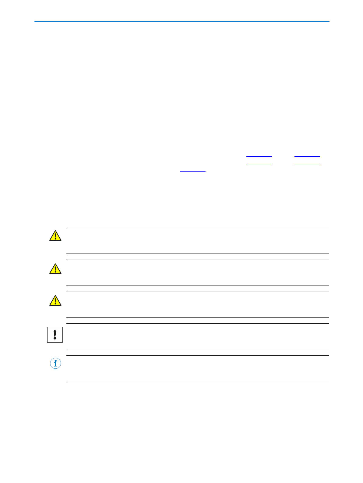
3.1 Scope of delivery
NAV-LOC is available in a range of variants depending on the requirements:
The delivery of NAV-LOC includes the following components:
No. of
units
Component
1
2D LiDAR sensor
1
SIM2000-0A20A00 including embedded application for localization
Please note: Cables for the voltage supply and data lines are not included with delivery and can optionally be ordered as accessories.
No. of
units
Additional accessories1
1
Power cabling for 2D LiDAR sensor: M12 A-coded, 5-pin
1
Ethernet cabling for 2D LiDAR sensor: (RJ45 to M12, D-coded)
1
Power cabling for SIM2000-0A20A00
Ethernet for SIM2000 to vehicle controller: RJ45 to RJ45
Sources for obtaining more information
Additional information about the SIM2000-0A20A00 and the 2D LiDAR sensor and their optional accessories can be found in chapter 1.3.
1
Additional accessories like power and network cabling or mounting brackets can be ordered at the
NAV-LOC product page. Under option “recommended accessories” is the minimum setup material.
Page 11
3 Product description
8021386/12G4 /2019-04-24 | SICK OPERATING INSTRUCTIONS | NAV-LOC
11
Subject to change without notice
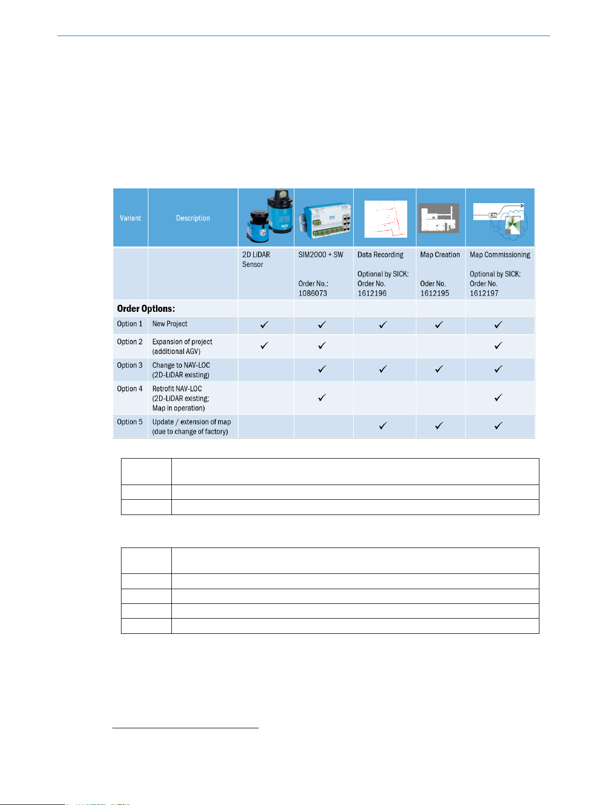
3.2 Design and function of NAV-LOC
NAV-LOC is intended for determining the position of automated guided vehicles (AGVs). The vehicle
positions are calculated based only on contour data observed at the respective position.
Figure 1: System overview for the integration of NAV-LOC
The vehicle surroundings are measured using laser beams based on the measured data of a 2D LiDAR
Sensor. The current position is calculated based on contour data and a previously created reference
map. This is transmitted to the vehicle controller as x-/y- coordinates and a yaw angle together with a
time stamp. The vehicle computer controls the AGV along the programmed route and corrects any route
deviation with the help of NAV-LOC.
An absolute coordinate system with an origin must be defined for the use of NAV-LOC for position output. For example, the origin point of the coordinate system can be at the corner of a factory hall.
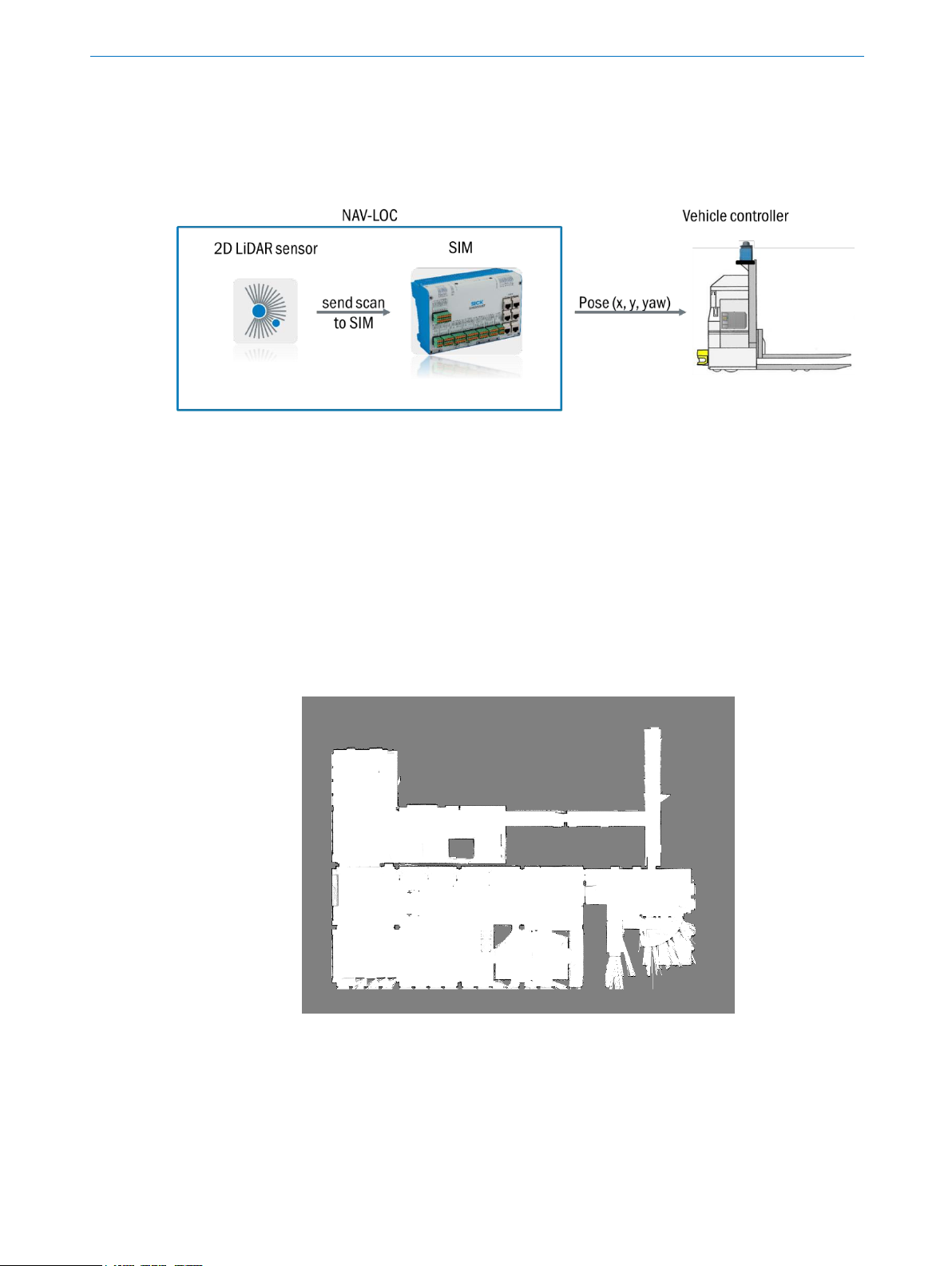
For the commissioning of NAV-LOC, a reference map of the current surroundings must have been created and installed (loaded).
Contact your SICK Service to create a reference map for your plant.
Figure 2: Example of a reference map for localizing in an industrial environment.
Page 12

3 Product description
8021386/12G4 /2019-04-24 | SICK OPERATING INSTRUCTIONS | NAV-LOC
12
Subject to change without notice
Device view:
Examples for a
2D LiDAR sensor
SIM2000-0A20A00 including NAVLOCs embedded application software
3.3 Sensor Integration Machine (SIM)
Additional information on the SIM2000-0A20A00 with notes on mounting, installation, and commissioning can be found online in the operating instructions2.
3.4 Measurement accuracy
The achievable measurement accuracy of NAV-LOC depends on the respective conditions during the
ride and their influence on the recording of measurement data.
The measurement accuracy in drive mode is influenced by:
The accuracy of the 2D LiDAR sensor used
Limitation of the visual range due to vehicles, persons and objects
Speed of the vehicle (particularly rotational movements)
Distance between vehicle and contour
Degradation of measurement performance due to fog, dust and like
Evenness of the route (e.g., uneven areas, ramps, and bumps)
Permanent changes to the surroundings (e.g. newly-built racks and walls/doors)
NOTE
The measurement accuracy specifications are listed in the data sheet in chapter 12.
3.5 Telegram listing
The specific CoLa A (Command Language ASCII) commands for communication between the SIM module and the vehicle controller is described in a separate document3.
3.6 Data interfaces
The SIM features 4 Ethernet interfaces for the connection to the network of the vehicle, which also
contains the 2D LiDAR sensor.
3.7 Diagnosis
The operation state of the embedded application can be monitored via three ways:
Via LED
Via SOPAS AIR web GUI
Via CoLa telegram
2
Open the page www.sick.com and enter the part number of the operating instructions of the SIM2000
(German 8020763, English 8020764) into the search field.
3
Open the page www.sick.com and enter the part number of the NAV-LOC telegram listing 8021387
(English) into the search field.
Page 13
3 Product description
8021386/12G4 /2019-04-24 | SICK OPERATING INSTRUCTIONS | NAV-LOC
13
Subject to change without notice
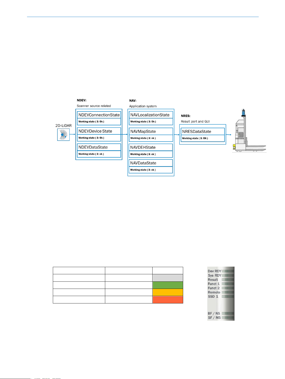
In the CoLa communication, there are also three function blocks (NDEV, NAV and NRES) which have to
be initialized for the reception of data via the result port.
NDEV:
Handles the communication between NAV-LOC and the connected 2D LiDAR sensor
NAV:
Is responsible for the map handling and the localization.
NRES:
Handles the results (localization with pose and scan results) from NAV-LOC.
Besides the correct initialization, also following root causes may be checked:
Power supply of 2D LiDAR sensor
2D LiDAR sensor type
Interfacing of 2D LiDAR sensor as type, cable, IP address
3.7.1 Diagnostic via LED status indicators
When the device is operating, the operational status is indicated visually by status LEDs.
Using these status indicators, the operator can find out quickly and easily whether the device and the
peripherals are working properly or whether any faults or errors have occurred.
Monitoring the visual indicators is part of the routine inspection carried out on the device and the ma-
chine/plant area into which the device is incorporated.
The SIM LEDs are controlled by the embedded application and signal different states.
Meaning of display
Action
Color
Idle- / Interim state
Wait
Grey
Ok
No action required
Green
Warning
Act, if necessary
Yellow
Error
Action required
Red
Page 14
3 Product description
8021386/12G4 /2019-04-24 | SICK OPERATING INSTRUCTIONS | NAV-LOC
14
Subject to change without notice
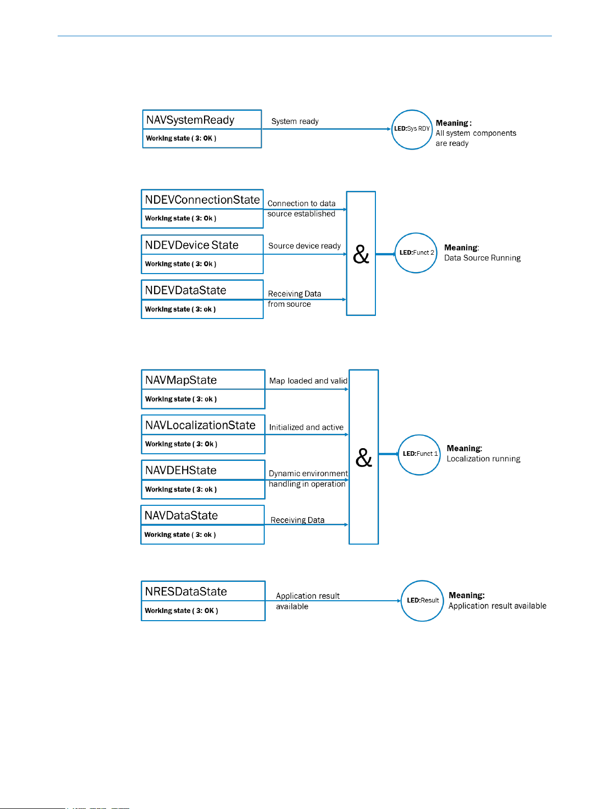
The following schematics illustrate the logical operation for the LEDs.
Figure 3: States related to the system
Figure 4: States related to the data source NDEV (2D LiDAR sensor)
Figure 5: States related to the application:
Figure 6: States related to the application:
3.7.2 Diagnostic via SOPAS AIR
A further analysis could be done via the SOPAS Air interface. The logical states are shown in the visualization. For a working condition, the simulated LEDs shall show a green light.
Page 15

3 Product description
8021386/12G4 /2019-04-24 | SICK OPERATING INSTRUCTIONS | NAV-LOC
15
Subject to change without notice
States related to the data source NDEV (2D LiDAR sensor):
States related to the application:
3.7.3 Diagnostic via telegram
For the diagnostic via telegram, please refer to the telegram listing document chapter “Status com-
mands (read-only)”4.
3.8 Reference map
A reference map which shows the contour of the factory site is required for operation of the localization
system.
Contact your SICK Service to create a reference map for your plant. You will find a contact address for
your country on the last page of this document.
When mapping, the factory site is measured from the point of view of the 2D LiDAR sensor and entered
in a reference map.
Either a movable frame with a battery can be used, whereby the 2D LiDAR sensor must be aligned on
the same level as on the designated AGV, or the AGV with the mounted 2D LiDAR sensor is moved with
the manual control.
4
Open the page www.sick.com and enter the part number of the NAV-LOC telegram listing 8021387
(English) into the search field.
Page 16

3 Product description
8021386/12G4 /2019-04-24 | SICK OPERATING INSTRUCTIONS | NAV-LOC
16
Subject to change without notice
Example for measurement device Example for AGV with NAV310
The two steps for creating a reference map are shown below.
Architecture drawing Step 1: Raw data Step 2: Completed reference map
(Red: measured area)
The contour visible from the sensor is dependent on the installation height of the 2D LiDAR sensor.
That is why it is necessary to observe the configuration notes in chapter 4.2 “Requirements for the
position of the 2D LiDAR sensor” when selecting the scan height and preparing the sensor for map
creation.
A coordinate system (x, y) is defined for the reference map in which the position and orientation of the
sensor is determined numerically during localization. The orientation and the origin point of this coordinate system can only be configured when creating the map and must therefore be defined for the
respective plant before creating the reference map.
The reference map must be loaded on the SIM to operate NAV-LOC. This step is described in chapter
7.5.
The map used must cover the entire vehicle operation area.
If needed, for example when operating on different levels connected by an elevator, different reference
maps can be used. However, only one map can be active at a time.
NOTE
If modifications are made in the factory site which result in a considerable change to the contour visible
from the sensor, for example due to modified walls, racks or other large structures, the accuracy of the
localization in the affected area is reduced or the localization itself is impaired. In this case, the affected
area must be re-mapped. Contact SICK Service about this.
The reference map is in the *.smap data format. You will receive a graphic representation of the reference map documentation. An imprinted grid enables orientation.
Page 17
3 Product description
8021386/12G4 /2019-04-24 | SICK OPERATING INSTRUCTIONS | NAV-LOC
17
Subject to change without notice
3.9 Dynamic Environment Handling
The Dynamic Environment Handling enables that contour navigation is stable even when small and
gradual changes are made to the surroundings.
The system detects deviations between the visible contour and the saved reference map. All detected
deviations from the saved map are written to an internal additional layer, while the original map file
remains unchanged.
The system uses the reference map and the deviations described in the working map to obtain enough
valid ambient properties to ensure stable localization.
At the same time, NAV-LOC outputs additional information, which is described in chapter 3.11. The
parameter described there, Local Map Modification, defines the extent of the adjustment performed
in the current surroundings.
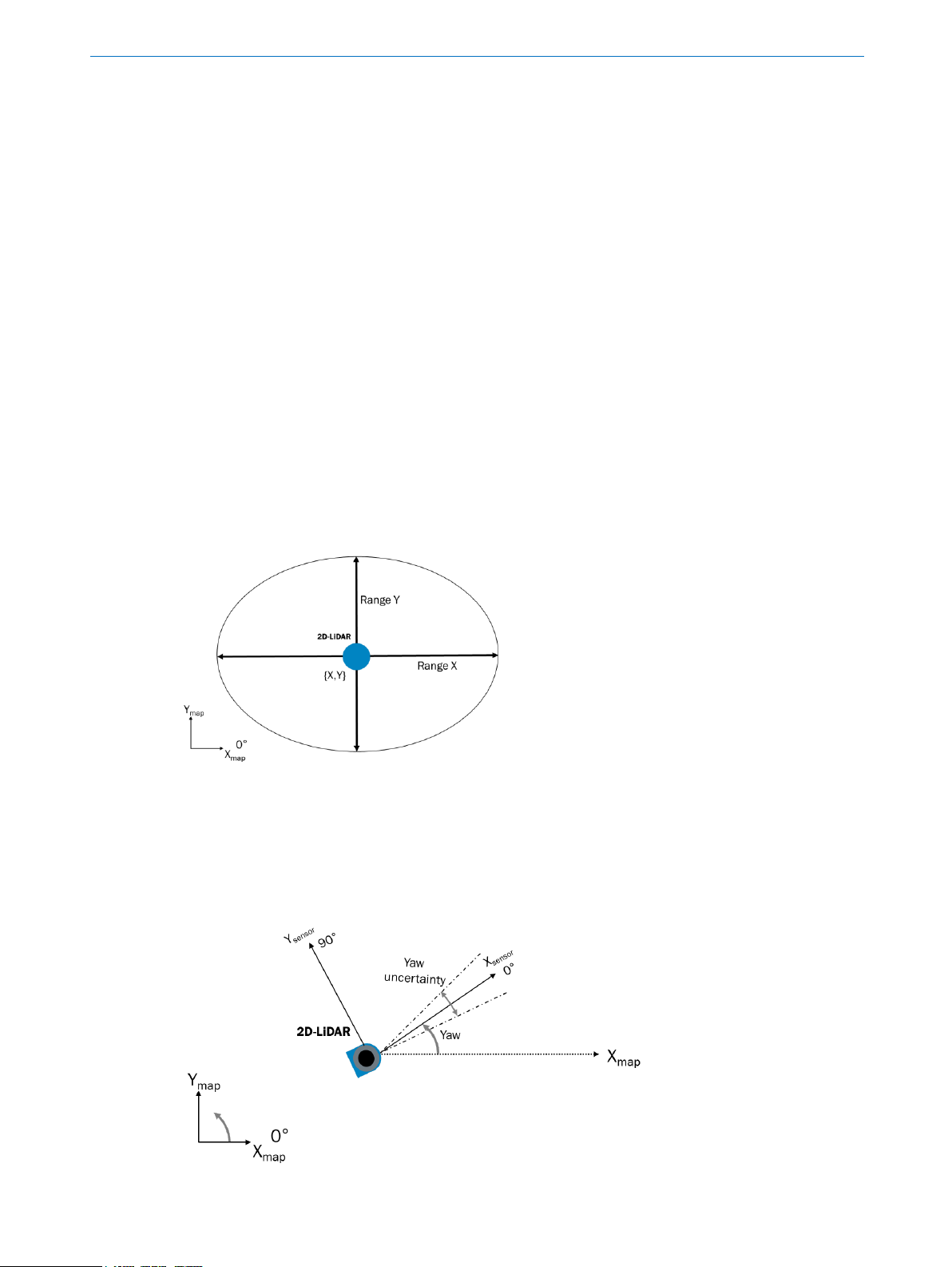
3.10 Initial position
When switching on localization mode, the position in the coordinate system of the reference map must
be provided to the system one time. Required is the information about the current position (x, y) and
the orientation angle. A value for uncertainty (“uncertainty range”) for all three coordinates has to be
specified for the provided position.
3.10.1 X,Y (position uncertainty)
The {X,Y} position is defined according to the maps global coordinate system. The corresponding uncertainty value in x and y specifies the area around this specified position within which the actual position is located. The range is also specified in accordance to maps global coordinate system.
3.10.2 Yaw (orientation uncertainty)
The orientation and uncertainty of the yaw angle are to be provided accordingly. In difference to the xy-pose, the alignment of the 2D LiDAR sensor in the maps global coordinate system must be considered. The X-axis (in direction of LEDs) defines the sensor orientation and the direction the 2D LiDAR
sensor is pointing to.
Page 18
3 Product description
8021386/12G4 /2019-04-24 | SICK OPERATING INSTRUCTIONS | NAV-LOC
18
Subject to change without notice
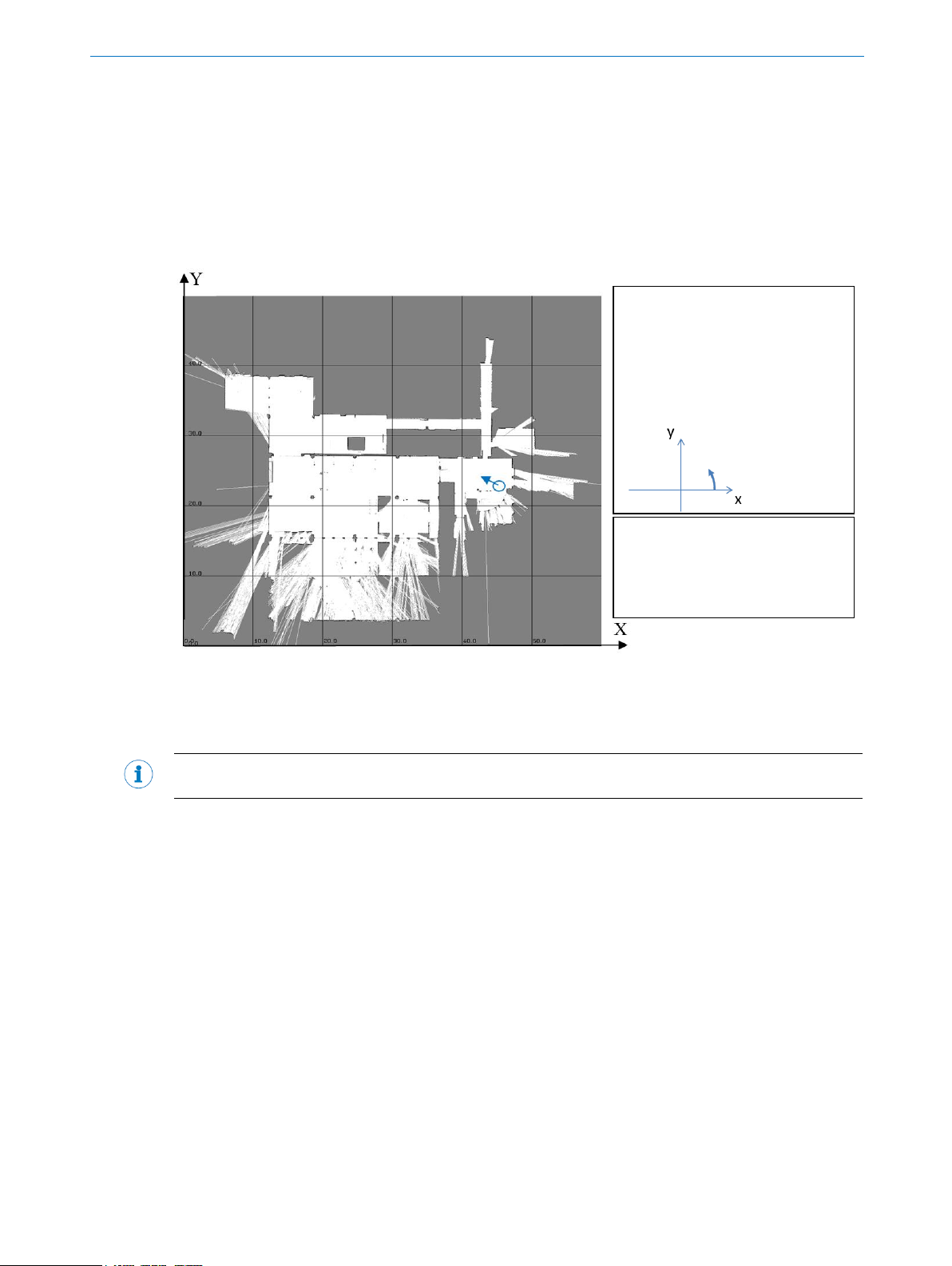
3.10.3 Environment specific considerations
The map required for localization is provided in *.smap format by SICK Service.
It is loaded onto the SIM, as described in chapter 7.5.
In addition, SICK Service provides documentation of the reference map, which features a grid, in *.pdf
format. This grid can be used to estimate the initial position.
For example, a grid image of the factory system could be displayed for operation using the touch screen
of an automated guided vehicle system. An operator could use this grid to specify the initial position.
Example of map documentation with coordinate system and grid
The specified position and orientation must correspond with the current position of the AGV in the map
coordinate system and should be within a position uncertainty of ± 5 m and ± 15°from the actual position and orientation. Depending on the environment, it may be necessary to specify an initial position
with a higher accuracy.
NOTE
The following contains descriptions of situations which require closer inspection of the uncertainty.
During initial positioning, there are different requirements for the uncertainty range depending on the
surroundings.
Some situations are described below in which increased requirements for the accuracy of the initial
position and the uncertainty range exist.
Example for an initial position:
X-coordinate: 45 m
Y-coordinate: 23 m
Orientation angle: 140°
Map dimensions:
X: 0.0 – 60.0 m
Y: 0.0 – 50.0 m
Grid size: 10.0 m
Orientation angle:
Page 19

3 Product description
8021386/12G4 /2019-04-24 | SICK OPERATING INSTRUCTIONS | NAV-LOC
19
Subject to change without notice
Initial situation
Vehicle is located at position A.
The sensor measures the contours marked in red as scan data.
Problem
The vehicle is at position A, but during initial localization,
position B is entered as the initial position (incorrectly).
The measured contour of the 2D LiDAR sensor matches to the expectation from the map for position
B.
=> The system is localized to the incorrectly specified initial position B.
(A perfect match of the contour to the map is not necessary here.)
Solution
The initial position must be sufficiently accurate in surroundings with repetitive structures. An initial
position must not deviate from the actual position by more than half of the repeat grid (here: aisle
distance).
Page 20

3 Product description
8021386/12G4 /2019-04-24 | SICK OPERATING INSTRUCTIONS | NAV-LOC
20
Subject to change without notice
That means the uncertainty range must be smaller than the grid of the hall aisles or the distances
between the structures/columns.
In the following situations, it must also be ensured that the initial position is accurate enough due to
the repeating surrounding structure.
Example of aisle/corridor
The vehicle is located at position A in an aisle with a column grid repeating at a short distance.
The walls cannot be measured at the front and rear since they are outside of the range of the 2D LiDAR
sensor.
The sensor only receives the contour located on the side as scan data.
The uncertainty range must not exceed the grid dimensions of the columns grid here: uncertainty range
= column distance
Example of factory hall with columns
The vehicle is located at position A in a hall with a repeating column grid.
The walls can be measured depending on the position only to one side since the other walls are outside
the range of the 2D LiDAR sensor.
The uncertainty range must also not exceed the grid dimensions of the columns here:
uncertainty range = column distance.
Page 21

3 Product description
8021386/12G4 /2019-04-24 | SICK OPERATING INSTRUCTIONS | NAV-LOC
21
Subject to change without notice
3.11 Output of position and additional information
Outputs of the NAV-LOC system are:
Current position (X,Y) in the coordinate system of the reference
map
Current yaw angle in the coordinate system of the reference map
Pose quality of the detected position
Status of the localization
- initializing: localization initializes to the stated position
- halted: localization detects that the vehicle is stationary
- running: localization continuously calculates the vehicle position
A time stamp in milliseconds is also output in the telegram for every position output.
Map dimensions:
X: 0.0 – 60.0 m
Y: 0.0 – 50.0 m
Grid size: 10.0 m
Orientation angle:
Example for position output:
X-coordinate: 24 m
Y-coordinate: 24 m
Orientation angle: 0°
3.11.1 Pose quality
In addition, a quality assessment of the detected “pose quality” position is output which specifies the
reliability of the pose result. Its values are represented in a range of 0 to 100.
NOTE
The quality value does not show the accuracy of the pose, but the values indicate the stability of the
localization process, which led to the pose result.
Individual outliers should be observed, but should not cause immediate reaction.
The following ranges can be used for orientation:
High level of accuracy: typ. 0 – 30
A high level of accuracy with the data given below in the data sheet requires optimum application conditions.
For accurate localization as defined by the data sheet, the average value should stay below 30.
Page 22

3 Product description
8021386/12G4 /2019-04-24 | SICK OPERATING INSTRUCTIONS | NAV-LOC
22
Subject to change without notice
Stable localization: typ. 0 – 60
Stable localization means that an unambiguous and reliable position can be detected. For stable localization, the average quality value should stay below 60.
Please note: This value range does not apply for initial localization. During initialization, wait until the
value has reached a “stable” range.
Further causes for a high value in the quality assessment are:
Large deviations of the surroundings from the reference map
Speed/yaw rate of the vehicle is too high
The 2D LiDAR sensor optics are dirty or need to b cleaned
The following causes lead to a deviation of the measured scan to the map:
The vehicle is moving on a ramp
The vehicle is deformed by a load which changes the scan plane
The 2D LiDAR sensor is not horizontally aligned
3.11.2 Advanced options
Check “show advanced” to display more information.
Dynamic Object Ratio [%]
A filter reduces measurement noise to increase the stability of position determination.
The proportion of measuring beams that were filtered out is output. A high value indicates a high ratio
of dynamic changes in the surroundings.
Outlier Ratio [%]
Proportion of measuring beams which could not be assigned to the current reference map.
A low value means the current measurement data largely hits objects included on the map. A high value
means many of the objects currently being detected by the sensor have not yet been entered in the
reference map.
Local Map Modification [%]
Shows the percentage of available measuring beams which deviate from the initial reference map.
A low value means many of the measuring beams currently available have already been entered in the
reference map created originally. A high value means many of the objects currently used for localization
on the map were not entered in the initial reference map; rather, they were entered during operation
by the algorithm of the Dynamic Environment Handling.
Page 23

3 Product description
8021386/12G4 /2019-04-24 | SICK OPERATING INSTRUCTIONS | NAV-LOC
23
Subject to change without notice
Map Changes
Number of map changes made using this measurement data update.
A value of zero means the Dynamic Environment Handling (DEH) function has not yet made any
changes to the map. A value greater than zero means the DEH function has made changes to the map.
The changes from the DEH algorithm are not made in every localization step; rather, a number of
changes are always grouped together and then entered in the map together.
Adaptive map adjustment is only performed if the following parameters remain within a defined range:
Local Map Modification
< 50%
Yaw Rate
< 8°/s
Pose Quality
< 30
Figure 7: AGV block diagram
Page 24

4 System requirements of NAV-LOC
8021386/12G4 /2019-04-24 | SICK OPERATING INSTRUCTIONS | NAV-LOC
24
Subject to change without notice
4 System requirements of NAV-LOC
4.1 Requirements for the environment
The following requirements exist for using NAV-LOC:
The system is suited for navigation in closed buildings with even floors.
Walls, columns, and other fixed structures represented in the map must be sufficiently visible from
all positions in the building.
Installation of the components in the temperature range and with IP protection acc. to data sheet
Note: SICK Service can make a professional assessment of the factory site and then create the
map.
4.2 Requirements for the 2D LiDAR sensor
Ideal mounting is at a height above the heads of workers since typically only small changes of the
surroundings are expected here.
The sensor must be installed at a height which offers a good field of vision of the fixed elements of the
facility (for example walls, columns, fixed racks) from every location.
The sensor height should be above the height of movable objects.
NOTE
During installation, make sure that the visual range of the 2D LiDAR sensors is not restricted.
However, NAV-LOC is tolerant of individual movable objects protruding into the scan plane; this should
be the case only for a limited part of the scan data of the 2D LiDAR sensor for optimal accuracy at every
point. This means that 100% of the scan data does not necessarily have to match the map, but rather
that the system works even if the scan data deviates a bit from the contour, for example due to small
changes to the hall (e.g., single pallets or other vehicles) or covering by moving objects.
The sensor should not be installed at the height of wall projections or other objects, which can result
in ambiguity when measuring the distance to the wall. Instead, the sensor height should be selected
above or below the threshold so that it is clear which part of the building contour the sensor is meas-
uring.
See also the figure below:
The 2D LiDAR sensor should be installed according to the description in the operating instructions. It
should be possible to tilt the sensor mount in all directions in order to be able to align the sensor
horizontally so that the scan plane of the sensor runs parallel to the floor surface.
The sensor must be fixed to a vehicle on a way that the alignment of the sensor cannot be changed on
accident.
Ideally, the sensor alignment is done in an area with an even floor area intended for service work. As a
minimum requirement, an alignment should be carried out with a spirit level.
Page 25

4 System requirements of NAV-LOC
8021386/12G4 /2019-04-24 | SICK OPERATING INSTRUCTIONS | NAV-LOC
25
Subject to change without notice
Alternatively the SICK Alignment Tool, order no. 2101720, may be used.
This device is operated by an internal rechargeable lithium-ion battery and indicates the received laser
beam depending on the beam size by one or more red LEDs.
Figure 8: SICK Alignment Tool order no, 2101720
Page 26

5 Operating modes of NAV-LOC
8021386/12G4 /2019-04-24 | SICK OPERATING INSTRUCTIONS | NAV-LOC
26
Subject to change without notice
5 Operating modes of NAV-LOC
The embedded application has 3 main operating modes. After connecting the supply voltage and start-
ing, the embedded application is in IDLE mode.
There are two ways to switch states IDLE READY PREPARE LOCALIZE, either by setting the
relevant parameter or, if parameters are permanently saved, with a separate command.
The embedded application is switched to LOCALIZE mode by specifying the reference map and initial
position.
The map and the initial position can also be permanently saved and invoked for the initialization.
5.1 IDLE mode
The embedded application is started and all functions are ready for operation. In this state, at least the
Dev RDY and Sys RDY LEDs are green and communication can be established with the SIM.
5.2 READY mode
After assigning a valid data source, the embedded application switches to READY mode. This will be
indicated by the Funct2 LED.
NOTE
When switching from IDLE to READY mode, take the start times of the connected 2D LiDAR sensors
into account. The typical start times are approx. 10 s for the NAV310 and approx. 40 s for the NAV245.
NOTE
If the connection for the data source is set and permanently saved, the mode can be switched directly
from IDLE to READY via the sMN NAVSetActiveState command.
Page 27

5 Operating modes of NAV-LOC
8021386/12G4 /2019-04-24 | SICK OPERATING INSTRUCTIONS | NAV-LOC
27
Subject to change without notice
5.3 PREPARE mode
It can take several seconds to initialize a pose with a large reference map.
During loading, the system uses PREPARE to indicate that the mode is being changed.
5.4 LOCALIZE mode
The embedded application has been assigned a valid data source and is acquiring scan data.
After loading a map and setting the initial position, the embedded application switches to LOCALIZE.
The embedded application cyclically runs a comparison of the contour data detected by the 2D LiDAR
sensor and the previously stored and selected reference map.
The embedded application detects the global position based on this.
Overview
IDLE mode READY mode LOCALIZE mode
Application ready
Embedded
application started
Connection to data
source established
Data source pro-
vides scan data
Map valid and loaded
Initial position specified
Localization in operation
Page 28

6 Initial commissioning and demonstration mode
8021386/12G4 /2019-04-24 | SICK OPERATING INSTRUCTIONS | NAV-LOC
28
Subject to change without notice
6 Initial commissioning and demonstration mode
NOTE
This chapter describes only the initial, first set-up and demonstration process. For further information
refer to chapter 7.
6.1 Initial connection setup
1. Setting up connections for power supply like described in chapter 7.3 and for the network connec-
tions like described in chapter 7.4.
2. Open the SOPAS AIR web GUI with a web browser (Chrome is preferred) e. g. with default setting:
http://192.168.0.1 for X9-1 from the connected SIM Port
Page 29

6 Initial commissioning and demonstration mode
8021386/12G4 /2019-04-24 | SICK OPERATING INSTRUCTIONS | NAV-LOC
29
Subject to change without notice
3. Configure the data source (2D LiDAR sensor) corresponding to chapter 7.6.2. If default settings
are used this is:
Source type: TCP/IP
Active source IP: 192.168.1.10
5
Active source port: 2111
6.2 Creating a demo map
A map of the current surroundings can be created via the visualization for demonstration purposes or
for a test of the function of NAV-LOC.
The surroundings are limited to a size of 50 x 50 m.
NOTE
The created demo map is used for initial commissioning of NAV-LOC and is not suitable for driving
operation.
NOTE
This map can only be created statically, i.e., the sensor must not be moved and must be mounted so
that its scan plane runs parallel to the ground when the map is being recorded.
NOTE
Before creating the map, the communication parameters must be entered and the system state must
be READY.
5
The source IP and the port number can be switched via SOPAS ET (search on sick.com for SOPAS
Engineering Tool).
Page 30

6 Initial commissioning and demonstration mode
8021386/12G4 /2019-04-24 | SICK OPERATING INSTRUCTIONS | NAV-LOC
30
Subject to change without notice
1. Click on “Map Demo” to create a map of the current surroundings:
2. Press “Apply” to use the automatically inserted configuration
3. If all indicators are green, switch to the next tab “Run Monitor”
4. After switching to the “Run Monitor” page, the currently measured contour is shown in black and
the active map in yellow. The position with a trace of recent locations is shown in orange color.
Page 31

7 Full Integration and commissioning
8021386/12G4 /2019-04-24 | SICK OPERATING INSTRUCTIONS | NAV-LOC
31
Subject to change without notice
7 Full Integration and commissioning
7.1 Notes and preparatory information
The following steps should have been carried out prior to commissioning:
Electrical and mechanical installation is complete.
This must be done in accordance with the supplementary device-specific documents for 2D LiDAR sen-
sors, which can be combined with the SIM2000-0A20A00 as a data source. These are required in
addition as they describe the specific connection options and configuration for each sensor. The fol-
lowing information is available for download from this page:
NAV-LOC: SIM2000, NAV310 operating instructions (German 8023449, English 8023450)
NAV-LOC: SIM2000, NAV245 operating instructions (German 8023451, English 8023452)
Additional information on the SIM2000-0A20A00 with notes on mounting, installation, and commis-
sioning can be found online in the operating instructions6.
The sensor is aligned horizontally, which ensures no areas within the sensor’s field of view are
concealed.
The scan data of the facility has been recorded and a reference map has been created.
IMPORTANT
NAV-LOC must only be commissioned by adequately qualified personnel. Before operating the plant
fitted with NAV-LOC for the first time, make sure that it is first checked and released by qualified per-
sonnel.
NOTE
In addition, the following information must be taken into consideration to ensure an efficient commis-
sioning process:
Only connect those devices to the SIM that you want to configure or program.
Operate the connected NAV-LOC in a controlled and contained network environment for the time
being to check network communication if necessary.
Note the company standards that apply to the use of checking and testing devices.
Use an environment with a simple room contour for initial commissioning.
Localization
system (NAV-LOC)
Mission
handling
Route
planning
Motion
control
Motor drivers
Pose (x, y, yaw)
Path planning
Traffic
management
Order
management
Mission
management
Pose (x, y, yaw)
Vehicle
(on board)
Fleet management
(external)
Initial configuration
Figure 9: AGV and fleet management communication block diagram
6
Open the page www.sick.com and enter the part number of the operating instruction of the SIM2000
(German 8020763, English 8020764) into the search field.
Page 32

7 Full Integration and commissioning
8021386/12G4 /2019-04-24 | SICK OPERATING INSTRUCTIONS | NAV-LOC
32
Subject to change without notice
7.2 Required software
For the integration of NAV-LOC is some additional desktop software required:
FTP client for transmission of the maps from the PC to NAV-LOC
7
Web browser to operate the SIM
8
SOPAS ET
9
to configure of the Ethernet interfaces of the SIM and the NAV sensors.
7.3 Power supply
The supply voltage for the SIM is 24 V DC, ± 10% ES1 acc. to EN 62368-1 or SELV acc. to EN 60950-1.
The power consumption is typically 20 W.
Figure 10: SIM connectors overview
(1) X1 - IO LINK MASTER
(2) X2 - POWER
(3) X3 - OUTPUT
(4) X4 - INPUT A
(5) X5 - INPUT B
(6) X6 - SERIAL A
(7) X7 - SERIAL B
(8) X8 - CAN
(9) X9 ... X12 - ETHERNET
(10) X13 ... X14 - FIELDBUS
7
E. g. The software Filezilla (client not server) is suitable for this purpose. This program can be down-
loaded online at https://filezilla-project.org/ and installed on the PC.
8
Google Chrome is recommended and supported (https://www.google.com/chrome).
9
Search on sick.com for SOPAS Engineering Tool.
Page 33

7 Full Integration and commissioning
8021386/12G4 /2019-04-24 | SICK OPERATING INSTRUCTIONS | NAV-LOC
33
Subject to change without notice
The connectors (1), (5), (6), (7), (8), and (10) are not used for NAV-LOC and must remain unconnected.
The supply voltage is connected with male connector X2 to pin 3 (24 V In1) and 2 (GND).
Figure 11: X2 – Power connections (24V IN1 and 24V IN2 are designed with redundancy)
The X2-power indicators10 light up if the connection is correct.
7.4 Network setup
7.4.1 SIM configuration
The SIM features 4 Ethernet interfaces. For each interface, an IP address is preconfigured. However, it
can be changed using the SOPAS ET software as described below.
The factory settings of the SIM2000-0A20A00 are shown in the following figure.
A PC can be connected to an Ethernet interface, for example to port X9-1, for setting the interface
configuration.
The interface of the PC must be set to an IP address in the range 192.168.0.2 – 192.168.255 in order
to reach the device using the interface with the IP address 192.168.0.1.
If necessary, the 4 Ethernet interfaces can be configured individually.
Logging into the device with the “Authorized Client” level with the password “client” is required.
10
LED 1 for power connection via X2:2 and X2:3, LED 2 for power connection via X2:5 and X2:6
192.168.0.1
192.168.1.1
192.168.2.1
192.168.3.1
Page 34

7 Full Integration and commissioning
8021386/12G4 /2019-04-24 | SICK OPERATING INSTRUCTIONS | NAV-LOC
34
Subject to change without notice
The interfaces can be adjusted in the Network/Interfaces -> Ethernet menu item.
When setting up the Ethernet interfaces, make sure that subnet masks of the 4 Ethernet interfaces do
not overlap.
Page 35

7 Full Integration and commissioning
8021386/12G4 /2019-04-24 | SICK OPERATING INSTRUCTIONS | NAV-LOC
35
Subject to change without notice
NOTE
When configuring the 4 Ethernet interfaces of the SIM, make sure to avoid an address conflict.
Example :
▸ IP address of an SIM interface: 192. 168. 1. 1
▸ Subnet mask 255. 255. 255. 0
11111111 11111111 11111111 00000000
=> None of the other network interfaces of the SIM can have an IP address from this range:
192.168.1.1 to 192.168.1.255
7.4.2 Connection setup
The Ethernet interface of the SIM can be used for direct connection of the sensor and the PC.
The connection set-up shown in Figure 12 is based on the default settings of the SIM 192.168.0.1
(Ethernet port X9-1) and 192.168.1.1 (Ethernet port X9-2) and a 2D LiDAR sensor.
The default IP address of the connected 2D LiDAR sensor may have to be changed to an address in
the range 192.168.1.2 to 192.168.1.255 in this exemplary case.
The Ethernet interface of the PC has to be set to an IP address in the range 192.168.0.2 to
192.168.0.255 in this exemplary case.
Figure 12: Example connection set-up for live view and configuration of NAV-LOC via a PC
Supplementary device-specific documents for 2D LiDAR sensors, which can be combined with the
SIM2000-0A20A00 as a data source. These are required in addition as they describe the specific con-
nection options and configuration for each sensor. The following information is available for download
from this page:
• NAV-LOC: SIM2000, NAV310 operating instructions (German 8023449, English 8023450)
• NAV-LOC: SIM2000, NAV245 operating instructions (German 8023451, English 8023452)
Additional information on the SIM2000-0A20A00 with notes on mounting, installation, and commis-
sioning can be found online in the operating instructions11.
11
Open the page www.sick.com and enter the part number of the operating instruction of the SIM2000
(German 8020763, English 8020764) into the search field.
Page 36

7 Full Integration and commissioning
8021386/12G4 /2019-04-24 | SICK OPERATING INSTRUCTIONS | NAV-LOC
36
Subject to change without notice
7.4.3 Switch usage
The vehicle control unit must have at least one Ethernet interface in order to communicate with NAV-
LOC.
NOTE
It is preferred to connect the LiDAR sensor directly to the network interface of the SIM2000, without
routing it through additional network switches.
When using a network switch, all components must be set in the same IP number range. In this config-
uration, access is possible from the PC and vehicle computer to the SIM and the 2D LiDAR sensor. The
IP address of the connected 2D LiDAR sensor must be configured accordingly.
Figure 13: Example connection for switch usage with same address room (IP addresses are exem-
plary)
Figure 14: Alternative, example connection for switch usage with direct connection to PC for configu-
ration and visualization (IP addresses are exemplary)
Page 37

7 Full Integration and commissioning
8021386/12G4 /2019-04-24 | SICK OPERATING INSTRUCTIONS | NAV-LOC
37
Subject to change without notice
7.4.4 Result port output
NAV-LOC sends telegrams over the interfaces described in Figure 10 to communicate with a connected
vehicle computer.
The position is output in the binary result port protocol. There is a separate document for this, which is
available for download at www.sick.com. Simply search for the number 8021387.
NAV-LOC provides the following values via its result port data interface:
Position in X- and Y-coordinates
Yaw angle
Time stamp
Quality indicator for localization
7.5 Transfering the reference map
Requirements
A reference map from the current surroundings is available and the map is stored as an *.smap file on
the PC or a USB stick. (More than one map file may be used in a facility.)
Contact your SICK Service to create a reference map for your facility.
An FTP client software, such as the Filezilla freeware, is required for transmission of the maps from the
PC to NAV-LOC.
The following parameters must be set to use Filezilla:
Server (current IP address or SIM): e.g., 192.168.0.1
User name: maps
Password: client
Port: 2300
Page 38

7 Full Integration and commissioning
8021386/12G4 /2019-04-24 | SICK OPERATING INSTRUCTIONS | NAV-LOC
38
Subject to change without notice
The map can be transmitted from the computer to the target directory of the SIM by clicking the right
mouse button and selecting “Upload”.
7.6 Configuration of the the embedded application
7.6.1 Invoking SOPAS AIR via web browser
NOTE
The same methods for operation and configuration can also be run directly from the vehicle control via
the CoLa A protocol, which is described in the telegram listing12.
The following shows how the embedded application is configured in the SIM using the “SOPAS AIR”
web-based interface.
The Chrome web browser is recommend for this purpose. The web interface is invoked by entering the
current IP address of the SIM, e.g., http://192.168.0.1 (factory default setting).
12
Open the page www.sick.com and enter the part number of the NAV-LOC telegram listing 8021387
(English) into the search field.
Page 39

7 Full Integration and commissioning
8021386/12G4 /2019-04-24 | SICK OPERATING INSTRUCTIONS | NAV-LOC
39
Subject to change without notice
7.6.2 IDLE: Data source settings
This chapter describes the communication between the sensor (data source) and the SIM.
The configuration for the connected 2D LiDAR sensor can be set in the field “Source Configuration”, for
example with:
Source Type: TCP/IP
Active source IP: 192.168.1.1013
Source Port: 2111
The inputs are entered when “Apply” is pressed.
Figure 15: Source configuration (settings for the data source) interface after successful connection
to the sensor
If the data is valid, a sensor is connected and ready for use, NAV-LOC will be initialized and started. The
state of NAV-LOC changes from IDLE to READY mode.
SIM LED INDICATOR
In IDLE mode, at least the Dev RDY and Sys RDY LEDs are green and communication can be established
with the SIM.
The Funct 2 LED lights up green when the device has successfully switched to READY mode.
IDLE mode READY mode
13
The source IP and the port number can be switched via SOPAS ET (search on sick.com for SOPAS
Engineering Tool).
Page 40

7 Full Integration and commissioning
8021386/12G4 /2019-04-24 | SICK OPERATING INSTRUCTIONS | NAV-LOC
40
Subject to change without notice
NOTE
When switching from IDLE to READY mode, take the start times of the connected 2D LiDAR sensors
into account. The typical start times are approx. 10 s for the NAV310 and approx. 40 s for the NAV245.
NOTE
If a connection between the NAV-LOC and the sensor is not achieved, the IP addresses of the sensor
and the used port of NAV-LOC should be checked with a direct connection to the SOPAS ET program
and corrected if necessary.
7.6.3 IDLE: Mounting Position (optional)
The navigation point of an AGV, where all position and path planning is related to, depends on the
kinematics of the vehicle. Typically, the position of the 2D LiDAR is not located exactly above this navi-
gation point. By entering the deviation from the positon of the sensor axis to the navigation point of the
vehicle by the parameters Mounting Pose X, Mounting Pose Y and Mounting Pose Yaw it is possible to
get the pose information transformed.
Figure 16: SOPAS AIR configuration or the mounting pose
For the exemplarily illustrated vehicle in Figure 17 the following values would apply:
Mounting Pose X: 1500 mm
Mounting Pose Y: 200 mm
Mounting Pose Yaw: 20°
Figure 17: Mounting parameter for 4-wheel vehicle
Page 41

7 Full Integration and commissioning
8021386/12G4 /2019-04-24 | SICK OPERATING INSTRUCTIONS | NAV-LOC
41
Subject to change without notice
For the exemplarily illustrated vehicle in Figure 18 the following values would apply:
Mounting Pose X: 2000 mm
Mounting Pose Y: -300 mm
Mounting Pose Yaw: -20°
Figure 18: Mounting parameter for 3 wheel vehicle, typical for forklifts
NOTE
The setting of mounting pose UpsideDown does not change the sensor coordinate system. The infor-
mation is used to convert the scan data to the NAV LOC system.
7.6.4 IDLE: Scan filter (optional)
If there are parts of the vehicle visible in the field of view of the sensor, the corresponding measure-
ments will lead to bad localization stability. The filter should be used to mute these scan sector areas.
One has to consider that the more the field of view of the sensor is restricted, the more difficult it is for
NAV-LOC to localize itself. The function therefore depends on the environment NAV-LOC is deployed in.
As indication to reach the full accuracy mentioned in the data sheet in chapter 12 one should not set
a scan range below of 220°. Lower values are possible, however, can lead to bad localization stability
depending on the environment.
As default value, the scans are not limited in angle and distance.
Page 42

7 Full Integration and commissioning
8021386/12G4 /2019-04-24 | SICK OPERATING INSTRUCTIONS | NAV-LOC
42
Subject to change without notice
The configuration values refer to the sensor position and orientation. There is one unique coordinate
definition within the NAV-LOC system to handle all LiDAR sensors. All data is transformed internally to
match the specific sensor system.
NOTE
The scan filter does also effect the output scan data via the result port.
Figure 19: Unique coordinate system for all LiDAR Sensors (angle in mathematical positive direction
– counterclockwise)
Example 1:
Distance Begin : 500 mm
Distance End : 200 000 mm
Angle Begin : -110 000 mdeg
Angle End : 110 000 mdeg
Page 43

7 Full Integration and commissioning
8021386/12G4 /2019-04-24 | SICK OPERATING INSTRUCTIONS | NAV-LOC
43
Subject to change without notice
NOTE
The field of view limits from start- to endpoint is counterclockwise (CCW). That means, if the value of
angle begin is higher than angle end, then the scans counting from 0° get suppressed.
Example 2:
Angle Begin : 45 000 mdeg
Angle End : -45 000 mdeg
7.6.5 READY: Settings for localization
A map suitable for the current surroundings must be selected and set for NAV-LOC for localization.
In addition, NAV-LOC needs a start range consisting of the initial position and uncertainty range (for
more information, see chapter 3.10).
NOTE
Use only integer values in the GUI –no floating point numbers are allowed.
Map Name example: Site.smap
X-coordinate [m]: 25 Uncertainty Range X [m]: 1
Y-coordinate [m]: 25 Uncertainty Range Y [m]: 1
Yaw angle [°]: 0 Uncertainty Range Yaw [°]: 10
Page 44

7 Full Integration and commissioning
8021386/12G4 /2019-04-24 | SICK OPERATING INSTRUCTIONS | NAV-LOC
44
Subject to change without notice
Chapter 7.5 describes how the map is transferred to the flash memory of the SIM. The information will
be entered when “Apply” is pressed.
If the data is valid, e.g. the selected map is available in the memory and can be used, the state auto-
matically changes to LOCALIZE and the localization is started.
Requirements for successful initial localization are:
The vehicle is stationary.
The surroundings are sufficiently visible and not occluded.
The initial position data specified by the operator via GUI or by the vehicle computer via tele-
gram consisting of X- and Y-coordinates and orientation match the actual position of the AGV.
NOTE
If the settings are correct, all LEDs turn green when changing from IDLE mode to LOCALIZE mode.
LED INDICATOR in READY mode on the SIM
The Funct 1 LED also lights up green when the device has successfully switched to LOCALIZE mode.
READY mode LOCALIZE mode
Page 45

7 Full Integration and commissioning
8021386/12G4 /2019-04-24 | SICK OPERATING INSTRUCTIONS | NAV-LOC
45
Subject to change without notice
At the end, press the button “edit” on the right side of SOPAS AIR
and click “Save permanently” afterwards to store all related data. Which data is stored, is described in
the telegram listing14 in the chapter for the corresponding command NAVSavePermanent.
7.6.6 LOCALIZE: Indication of contour and position
Requirements
All status messages on the “Run Monitor” page have a green status indicator.
After switching to the “Run Monitor” page, the currently measured contour is shown in black and the
active map in yellow.
The position with a trace of recent locations is shown in orange color.
For the “Position” options refer to chapter 3.11.
14
Open the page www.sick.com and enter the part number of the NAV-LOC telegram listing 8021387
(English) into the search field.
Page 46

7 Full Integration and commissioning
8021386/12G4 /2019-04-24 | SICK OPERATING INSTRUCTIONS | NAV-LOC
46
Subject to change without notice
Notes on using the 3D viewer:
In SOPAS Air, the 2D room contour, the map, and the position are shown with a 3D viewer.
The “Rotate” operating mode enables the contour display to be rotated by moving the mouse while
holding down the left mouse button.
In “Move” operating mode, move the mouse while holding down the left mouse button to move in the
X- and Y-direction.
Always switch from “Rotate” mode to “Move” mode first in order to make operation simpler.
The contour display can be zoomed in or out either by using the mouse wheel or the + or - pushbuttons.
7.6.7 LOCALIZE: Settings for the result port (data output)
To use the position data in the vehicle control computer, it can be connected to Ethernet port X9-1 or
a free port on a switch.
Port X9-1 has IP number 192.168.0.1 as a default setting, i.e., either the vehicle computer is set
suitably to, e.g., 192.168.0.3 or port X9-1 can be adjusted with the SOPAS ET program.
Data output between the embedded application and the vehicle computer is described in the telegram
listing (see chapter 3.5) and is preset via port 2201.
Different options can be set in “Basic Settings” of the SOPAS AIR interface.
There will be no data output via the result port without activating data output.
Page 47

7 Full Integration and commissioning
8021386/12G4 /2019-04-24 | SICK OPERATING INSTRUCTIONS | NAV-LOC
47
Subject to change without notice
Port 1 Configuration
Selection of the Ethernet port for data output, default setting is 2201.
Little Endian
Data is output in Big Endian format, i.e., the high byte (MSB) of the data values is output first. Depend-
ing on the processing method and processor type of the vehicle control computer, it is possible to
switch to Little Endian format. This switches the byte order of data output and the low byte (LSB) of the
data is output first. The change does not become effective until the system has changed to IDLE mode
once, then back to LOCALIZE mode.
Combine Telegrams
The data for the pose and the scans are transferred via the result port by default in separate telegram.
Some vehicle controllers have input buffers where the second received message may overwrite the
first received message. In this case the telegrams of pose and scans message could be combined to a
common telegram.
Scan Result Enabled
Enables the output of the scan messages from the connected LiDAR for further processing in the vehi-
cle controller e.g. for visualization.
NOTE
The scan data result refers to the LiDAR sensor’s position and orientation. The scan data is not pro-
cessed to an optionally configured mounting pose.
NOTE
All LiDAR scan data is transformed to one unique sensor coordinate system.
Figure 20: Unique coordinate system for all LiDAR sensors (angle in mathematical positive direction
– counterclockwise)
Page 48

7 Full Integration and commissioning
8021386/12G4 /2019-04-24 | SICK OPERATING INSTRUCTIONS | NAV-LOC
48
Subject to change without notice
Localization Result Enabled
Enables the output of the position with X- and Y-coordinates, orientation and including additional infor-
mation.
Scan Result Output cycle
Determines the output cycle of the output of scan data telegrams.
When 1 is entered, the scan data result telegrams are output for each measurement cycle. When 2 is
entered, the scan data result telegrams are only output every second scan measurement cycle. The
default value is 1.
Localization Result Interval
Determines the output cycle of the output position data telegrams.
When 1 is entered, the localization result telegrams are output for each measurement cycle. When 2
is entered, the localization result telegrams are only output every second scan measurement cycle. The
default value is 1.
NOTE
If necessary, the output frequency can be lowered with the pre-selectable output interval.
Page 49

8 Synchronization
8021386/12G4 /2019-04-24 | SICK OPERATING INSTRUCTIONS | NAV-LOC
49
Subject to change without notice
8 Synchronization
A very important aspect in the vehicle control is the time synchronization between the AGV vehicle
controller and the internal time stamp of the NAV-LOCs controller called SIM.
The clock of the AGV vehicle controller and the clock of the SIM must be synchronized periodically. For
motion control, it is necessary that the AGV controller can assign its own time stamp to each position
produced by NAV-LOC.
The system latencies without this synchronization is described in chapter 12.2.
The internal time stamp of the embedded application increases in increments of 1 every 1 ms.
Additionally, the time stamp of the embedded application is synchronized internally by the SIM with the
time stamp of the connected 2D LiDAR sensor. Each result (measurement data and localization result)
from NAV-LOC is then provided with the internal time stamp of the embedded application.
NOTE
For synchronization, CoLa A commands are used for communication between the SIM module and the
vehicle controller or your service computer, which is described in the separate document “Telegram
Listing”15.
NOTE
This chapter elaborates about the synchronization of NAV-LOC and between the AGV vehicle controller.
The synchronization between the connected 2D LiDAR sensor and the NAV-LOC controller (SIM) is done
internally by the embedded application of and is described in chapter 2.5 of each of the device-specific
documents:
SIM2000, NAV310 operating instructions (German 8023449, English 8023450)
SIM2000, NAV245 operating instructions (German 8023451, English 8023452)
8.1 Synchronization options
NAV-LOC has three options available for synchronizing the internal time of embedded application with
the system time of the vehicle computer.
8.1.1 Synchronization via telegram request (polling)
The vehicle computer retrieves the internal time of the embedded application using the NAVGet-
Timestamp telegram.
The embedded application writes its internal time into a telegram and sends this to the vehicle com-
puter.
Sending may happen with a delay time of up to a few milliseconds, which results in some uncertainty.
This can be overcome with the 2nd synchronization method.
An example could be to request the time stamp from NAV-LOC every 10 seconds.
15
Open the page www.sick.com and enter the part number of the NAV-LOC telegram listing 8021387
(English) into the search field.
Page 50

8 Synchronization
8021386/12G4 /2019-04-24 | SICK OPERATING INSTRUCTIONS | NAV-LOC
50
Subject to change without notice
8.1.2 Synchronization via telegram request (polling) and HW port
The vehicle computer retrieves the internal time of the embedded application using the telegram
NAVGetTimestamp
16
in the same way like used in option 1. Additionally, a hardware (HW) digital
output is set via NAVSyncGetTimestampPort. The hardware output provides a pulse of 128 ms
duration once the internal time stamp is written in the telegram.
Using the hardware port gives the option to calculate the delay for processing the request command
and the following response time.
An example could be to request the time stamp from NAV-LOC every 10 seconds.
NOTE
The vehicle computer is to be configured such that it responds to the risings edge of the output pulse.
After the vehicle computer has received the telegram, the AGV computer can correct the time difference
between the pulse and the reception of the time stamp included in the telegram.
As a result, the AGV computer can determine the actual time in NAV-LOC.
The following formula is used to calculate the resulting time offset after request of the sensor time
between the clock of the SIM and the clock of the vehicle computer:
Δt
offset
= TS
AGV
– t
transfer
– TS
NAV
Δt
offset
Resulting time difference (offset)
TS
AGV
Time stamp of the AGV computer
TS
NAV
Time stamp of NAV-LOC
t
transfer
Transfer time via the Ethernet interface
16
See telegram listing in the Telegram Listing publication
Page 51

8 Synchronization
8021386/12G4 /2019-04-24 | SICK OPERATING INSTRUCTIONS | NAV-LOC
51
Subject to change without notice
8.1.3 Synchronization via a cyclical pulse provided on HW port
The embedded applications time can also be configured via a telegram in order to generate an output
pulse of 512 ms duration based on the 32-bit counter in a fixed cycle.
Configuration is done via the NAVSyncClockInterval command. The output pulse is generated
at each counter overrun in the specified interval depending on the parameter. The specific hardware
port is set with NAVSyncClockPort. Using the hardware port gives the option to calculate the delay
for processing the request command and the following response time.
Examples:
NAVSyncClockInterval
Interval time
10
1,024 ms
12
4,096 ms
15
32,768 ms
Configuration of, e.g., 15 bits creates an output pulse every 32,768 ms.
The cyclical sync pulse is always triggered when the lower 15 bits of the counter are zero.
By using this sync pulse, the vehicle computer can synchronize with the clock of NAV-LOC.
NOTE
The vehicle computer is to be configured such that it responds to the rising edge of the output pulse.
Page 52

8 Synchronization
8021386/12G4 /2019-04-24 | SICK OPERATING INSTRUCTIONS | NAV-LOC
52
Subject to change without notice
The reference between the time stamp in the telegram, which refers to the position in relation to the
cyclical output is illustrated in the following diagram.
8.2 Setting of the hardware outputs
NOTE
This chapter is only for usage of option 1 (chapter 8.1.2) or 2 (chapter 8.1.3) for synchronization.
The connector X3 of the SIM is used for outputting the sync pulses. Four outputs, X3-1 … X3-4, are
available. One of these outputs of X3 can be selected with the commands NAVSyncGet-
TimestampPort
17
or NAVSyncClockPort. The command NAVSyncGetTimestampPort is
used to set the output port for the pulse when receiving the time stamp request (NAVGetTimestamp)
and NAVSyncClockPort is used for the selection for the output of the cyclical pulse.
Once the setting for the port is done, the output is triggered in each state of the system (IDLE, READY,
LOCALIZE) and if saved after re-boot.
NOTE
The output pulses of both hardware synchronization variants are available at the same time and also
on the same port. However, it is highly recommended to assign them to separate outputs of X3.
17
(See telegram listing in the Telegram Listing publication.)
Page 53

8 Synchronization
8021386/12G4 /2019-04-24 | SICK OPERATING INSTRUCTIONS | NAV-LOC
53
Subject to change without notice
Although the LEDs of X3 are already flashing when the output X3 is configured, the outputs of the SIM
must be supplied with an additional 24 V DC, since the outputs are galvanically separated from the
input.
Either the voltage supply of the outputs can be connected together with the supply of the SIM, or if
galvanic separation of the outputs is required, it can be supplied separately.
Page 54

9 Troubleshooting
8021386/12G4 /2019-04-24 | SICK OPERATING INSTRUCTIONS | NAV-LOC
54
Subject to change without notice
9 Troubleshooting
NOTE
Please, refer to the chapter 3.7 “Diagnosis” for general troubleshooting options.
9.1 Hints to the network connection
Please note: If a network connection between the SIM and the sensor cannot be established, the IP
addresses and the setting of the subnet mask of the sensor and the used port of the SIM should be
checked for a possible collision with a direct connection to SOPAS ET and corrected if necessary.
More detailed information can be found in chapter 7.4.
9.2 Hints to initialization
If the mode is not changed from READY mode to LOCALIZE during initialization, the following settings
should be checked:
If one or several LEDs do not light up, the following should be analyzed:
NOTE
Depending on which 2D LiDAR sensor is connected, it may take some time after localization starts until
the sensor provides data for localization.
Data source ready
Is the 2D LiDAR sensor correctly connected and was the interface correctly configured in the sensor
and in the SIM?
Telegrams:
<STX>sRN NDEVConnectionState<ETX>
<STX>sRN NDEVDeviceState<ETX>
<STX>sRN NDEVDataState<ETX>
Page 55

9 Troubleshooting
8021386/12G4 /2019-04-24 | SICK OPERATING INSTRUCTIONS | NAV-LOC
55
Subject to change without notice
Valid map loaded and initialized
Is a map loaded and was it called up with the correct name?
Telegram:
<STX>sRN NAVMapState<ETX>
Dynamic Environment Handling Active
Is a data source specified, a valid and available map loaded, and a suitable initial position specified?
Telegram:
<STX>sRN NAVDEHState<ETX>
Localization Active
Is the localization initialized and running?
Telegrams:
<STX>sRN NAVActiveState<ETX>
<STX>sRN NAVLocalizationState<ETX>
<STX>sRN NAVDataState<ETX>
Application Results Available
Is a valid map loaded (name and contents)? Was a valid initial position specified? Is the connected
sensor outputting data?
Telegrams:
<STX>sRN NRESDataState<ETX>
<STX>sRN ER1St<ETX>
9.3 Localization hints
Changes of the facility surroundings can cause that the map can no longer be used for the localization.
Please check whether moveable objects, which were placed in the area of operation after the map
creation can be removed in order to recreate the original contour.
If this is not possible, please contact SICK Service for a change of the map.
9.3.1 Localization does not start
Wait some time (time needed for booting: up to 60 seconds, time needed for loading the map: up to
80 seconds depending on the map size).
9.3.2 No localization data is output
"Localization result enabled" may need to be activated, see section 7.6.7.
It is possible that no scan data will be output from the sensor; in this case the sensor cables and
the settings of the data source must be checked.
9.3.3 Characters
If the map is not loaded properly, check if the map name contains only valid characters that are:
Latin letters: A-Z, a-z
Arabic numbers: 0-9
Specific signs: - (hyphen), _ (underscore).
Page 56

10 Transport and storage
8021386/12G4 /2019-04-24 | SICK OPERATING INSTRUCTIONS | NAV-LOC
56
Subject to change without notice
10 Transport and storage
10.1 Transport
For your own safety, please read and observe the following notes:
IMPORTANT
Damage to the device due to improper transportation.
The device must be packaged for transportation with protection against shock and damp.
Recommendation: Use the original packaging as it provides the best protection.
Transport should be performed by specialized staff only.
The utmost care and attention is required at all times during unloading and transportation on com-
pany premises.
Note the symbols on the packaging shortly.
Do not remove packaging until before mounting.
10.2 Transport inspection
Immediately upon receipt in Goods-in, check the delivery for completeness and for any damage that
may have occurred in transit.
In the case of transit damage that is visible externally, proceed as follows:
Do not accept the delivery or only do so conditionally.
Note the scope of damage on the transport documents or on the transport company’s delivery note.
File a complaint.
NOTE
Complaints regarding defects should be filed as soon as these are detected. Damage claims are only
valid before the applicable complaint deadlines.
10.3 Storage
Store the device under the following conditions:
Recommendation: Use the original packaging.
Do not store outdoors.
Store in a dry area that is protected from dust.
Do not package in airtight container, such that any residual damp can evapore.
Do not expose to any aggressive substances.
Protect from sunlight.
Avoid mechanical shocks.
Storage temperature and relative humidity: see information in the operating instructions of the
individual components.
For storage periods of longer than 3 months, check the general condition of all components and
packaging on a regular basis.
Page 57

11 Service and maintenance
8021386/12G4 /2019-04-24 | SICK OPERATING INSTRUCTIONS | NAV-LOC
57
Subject to change without notice
11 Service and maintenance
The housing screws of the SIM2000-0A20A00 and 2D LiDAR sensors are sealed.
Claims under the warranty against SICK AG will be rendered void if the seals are damaged or the de-
vices are opened. The housing must only be opened by authorized SICK service personnel.
Page 58

12 NAV-LOC data sheet
8021386/12G4 /2019-04-24 | SICK OPERATING INSTRUCTIONS | NAV-LOC
58
Subject to change without notice
12 NAV-LOC data sheet
12.1 NAV-LOC features
Feature
Value
Application
Localization based on contour data in the indoor area
Supported products
NAV310-3211, NAV340-3232, NAV350-3232, NAV245-10100
SIM2000-0A20A00 Sensor Integration Machine
Communication interface
Ethernet (10/100/1,000 Mbit)
Function: data output
Switching outputs
4, for synchronization
Position resolution18
1 mm
Angular resolution19
0.001°
Content of output localization
result
Position (X, Y, yaw angle)
Quality information for data fusion and diagnosis of surroundings
Map size
≤ 250,000 m² (per each of the 10 maps)
Max. number of supported
maps/areas
10
Translational velocity
≤ 2 m/s
Yaw rate (rotational velocity)
≤ 45°/s
Accuracies
2D LiDAR sensor
2D LiDAR sensor
Supported device
NAV310-3211
NAV340-3232
NAV350-3232
NAV245-10100
Aperture angle
360°
270°
Distance Range
10 %: 35m
90 %: 120 m
10 %: 18m
90 %: 50 m
Update rate
Typical 8 Hz
Typical 8.33 Hz
Accuracy20
(position measurement)
Typical 30 mm
Typical 35 mm
Accuracy21
(yaw angle)
Typical 0.1° ... 0.4°
Typical 0.1° ... 0.4°
Repeatability22
Typical 4 mm ... 17 mm
Typical 6 mm ... 22 mm
18
The resolution refers to the output localization result via the result port and can differ from the con-
nected sensor’s measurement resolution.
19
The resolution refers to the output localization result via the result port and can differ from the con-
nected sensor’s measurement resolution.
20
1 σ, observe the min. warm-up time of 30 minutes; real value depends on ambient conditions
21
1 σ, observe the min. warm-up time of 30 minutes; real value depends on ambient conditions
22
End position reached, observe the min. warm-up time of 30 minutes; real value depends on ambient
conditions
Page 59

12 NAV-LOC data sheet
8021386/12G4 /2019-04-24 | SICK OPERATING INSTRUCTIONS | NAV-LOC
59
Subject to change without notice
12.2 System latencies
The latencies described in the table below can be eliminated by the synchronization options described
in chapter 8. The remaining uncertainty for this synchronization between the 2D LiDAR sensor and the
SIM is with:
Digital I/O synchronization < 5 ms
23
and with
Network (wired) synchronization < 10 ms.
2D LiDAR sensor
Maximum latency after „start of scan“24
NAV245
typ. below 170 ms + network transfer time25
NAV310:
typ. below 260 ms + network transfer time
23
This value is reached only if one uses the additional digital synchronization port of the NAV310 and
NAV245. If not used or for all other 2D LiDAR sensors, the value for “Network (wired) synchronization”
holds true.
24
Despite the latency, the update rate keeps after initialization the rate specified in chapter 12.1.
25
The network transfer time is depending on the system setup.
Page 60

SICK AG | Waldkirch | Germany | www.sick.com
8021386/12G4
/en/2019
-04-24
Australia
Phone +61 3 9457 0600
1800 334 802 – toll-free
E-mail sales@sick.com.au
Austria
Phone +43 22 36 62 28 8-0
E-mail office@sick.at
Belgium/Luxembourg
Phone +32 2 466 55 66
E-mail info@sick.be
Brazil
Phone +55 11 3215-4900
E-mail comercial@sick.com.br
Canada
Phone +1 905 771 14 44
E-mail cs.canada@sick.com
Czech Republic
Phone +420 2 57 91 18 50
E-mail sick@sick.cz
Chile
Phone +56 2 2274 7430
E-mail chile@sick.com
China
Phone +86 20 2882 3600
E-mail info.china@sick.net.cn
Denmark
Phone +45 45 82 64 00
E-mail sick@sick.dk
Finland
Phone +358-9-2515 800
E-mail sick@sick.fi
France
Phone +33 1 64 62 35 00
E-mail info@sick.fr
Germany
Phone +49 2 11 53 01-0
E-mail info@sick.de
Hong Kong
Phone +852 2153 6300
E-mail ghk@sick.com.hk
Hungary
Phone +36 1 371 2680
E-mail ertekesites@sick.hu
India
Phone +91 22 6119 8900
E-mail info@sick-india.com
Israel
Phone +972 4 6881000
E-mail info@sick-sensors.com
Italy
Phone +39 02 274341
E-mail info@sick.it
Japan
Phone +81 3 5309 2112
E-mail support@sick.jp
Malaysia
Phone +6 03 8080 7425
E-mail enquiry.my@sick.com
Mexico
Phone +52 (472) 748 9451
E-mail mexico@sick.com
Netherlands
Phone +31 30 2044 000
E-mail info@sick.nl
New Zealand
Phone +64 9 415 0459
0800 222 278 – toll-free
E-mail sales@sick.co.nz
Norway
Phone +47 67 81 50 00
E-mail sick@sick.no
Poland
Phone +48 22 539 41 00
E-mail info@sick.pl
Romania
Phone +40 356 171 120
E-mail office@sick.ro
Russia
Phone +7 495 775 05 30
E-mail info@sick.ru
Singapore
Phone +65 6744 3732
E-mail sales.gsg@sick.com
Slovakia
Phone +421 482 901201
E-mail mail@sick-sk.sk
Slovenia
Phone +386 591 788 49
E-mail office@sick.si
South Africa
Phone +27 11 472 3733
E-mail info@sickautomation.co.za
South Korea
Phone +82 2 786 6321
E-mail info@sickkorea.net
Spain
Phone +34 93 480 31 00
E-mail info@sick.es
Sweden
Phone +46 10 110 10 00
E-mail info@sick.se
Switzerland
Phone +41 41 619 29 39
E-mail contact@sick.ch
Taiwan
Phone +886 2 2375-6288
E-mail sales@sick.com.tw
Thailand
Phone +66 2645 0009
E-mail marcom.th@sick.com
Turkey
Phone +90 216 528 50 00
E-mail info@sick.com.tr
United Arab Emirates
Phone +971 4 88 65 878
E-mail info@sick.ae
United Kingdom
Phone +44 1727 831121
E-mail info@sick.co.uk
USA
Phone +1 800 325 7425
E-mail info@sick.com
Vietnam
Phone: +84 8 6292 0204
H/P +84 94545 2999
E-mail sales.gsg@sick.com
Further locations at www.sick.com
 Loading...