

Page 1
Laser Positioning Sensor
Navigating the Route to improved productivity
Initial commissioning
Page 2

SoftwareStand
Copyright
Copyright © 2016
SICK AG Waldkirch
Auto Ident, Reute Plant
Nimburger Straße 11
79276 Reute
Germany
Trademarks
Windows 2000™, Windows XP™, Windows Vista™ and Windows 7™ are registered trademarks of Microsoft Corporation in the USA and other countries.
Adobe
®
Reader™ is a trademark of Adobe Systems Incorporated.
Version of the operating instructions
The latest version of these operating instructions can be obtained as PDF at www.sick.com.
NAV350 Laser positioning sensor
Operating Instructions
Software version described
Software/tool Function Status
NAV350 Firmware V 1.06
Device description NAV350 Device specific software module
for SOPAS ET
SOPAS ET Configuration software V 02.38 or higher
Software access to the NAV350 is password protected. The default factory setting for the
password is as follows:
User level Password
Authorised client client
The NAV350 laser positioning sensor is intended for use in industrial environments. When
used in residential areas, it can cause radio interferences.
V 1.000 or higher
2 © SICK AG · Germany · All rights reserved · Subject to change without notice
8013889/ZML0/2017-06-09
Page 3

Operating Instructions
NAV350
SoftwareStand
Table of content
1 About this document .......................................................................................................8
1.1 Function of this document .......................................................................................... 8
1.2 Target group ................................................................................................................8
1.3 Depth of information ................................................................................................... 8
1.4 Symbology used .......................................................................................................... 9
2 For your safety .............................................................................................................. 10
2.1 Authorised personnel ................................................................................................10
2.2 Correct use ................................................................................................................11
2.3 General safety notes and protective measures ......................................................12
2.4 Quick stop and Quick restart ....................................................................................13
2.5 Environmental protection ......................................................................................... 14
3 Product description ...................................................................................................... 15
3.1 Delivery ......................................................................................................................15
3.2 Construction of the NAV350 .....................................................................................16
3.3 Special features of the NAV350 ............................................................................... 18
3.4 Applications ............................................................................................................... 19
3.5 Operating principle of the NAV350 ..........................................................................19
3.6 Landmark detection ..................................................................................................23
3.7 Navigation ..................................................................................................................24
3.8 Output of measured values ......................................................................................31
3.9 Integration of the NAV350 in an AGV’s control system .......................................... 31
3.10 Planning .....................................................................................................................36
4 Mounting ........................................................................................................................ 43
4.1 Overview of the mounting steps ...............................................................................43
4.2 Preparations for mounting ........................................................................................43
4.3 Mounting and adjustment of the device ................................................................. 43
4.4 Dismantling the NAV350 ..........................................................................................44
5 Electrical installation ................................................................................................... 45
5.1 Overview of the installation steps ............................................................................45
5.2 Connections of the NAV350 .....................................................................................45
5.3 Preparing the electrical installation .........................................................................46
5.4 Undertaking electrical installation on the NAV350 ................................................47
6 Commissioning and configuration ............................................................................. 50
6.1 Overview of the commissioning steps ..................................................................... 50
6.2 SOPAS ET configuration software ............................................................................ 51
6.3 Establish communication with the NAV350 ............................................................51
6.4 Initial commissioning ................................................................................................ 55
6.5 Connection and test measurement ......................................................................... 56
6.6 Loading reflector data ...............................................................................................57
7 Maintenance ................................................................................................................. 58
7.1 Maintenance during operation .................................................................................58
7.2 Exchanging a NAV350 .............................................................................................. 59
8 Troubleshooting ............................................................................................................ 60
8.1 In the event of fault ................................................................................................... 60
8.2 Monitoring error and malfunction indications .........................................................60
8.3 Troubleshooting and rectification ............................................................................ 61
8.4 Detailed error analysis ..............................................................................................61
8.5 SICK support ..............................................................................................................62
8013889/ZML0/2017-06-09
© SICK AG · Germany · All rights reserved · Subject to change without notice 3
Page 4

SoftwareStand
NAV350 Laser positioning sensor
9 Technical specifications .............................................................................................. 63
9.1 Data sheet NAV350 .................................................................................................. 63
9.2 Dimensional drawings .............................................................................................. 65
10 Annex ............................................................................................................................. 66
10.1 Overview of the annexes .......................................................................................... 66
10.2 Ordering information ................................................................................................ 66
10.3 Glossary ..................................................................................................................... 67
10.4 EC declaration of conformity .................................................................................... 68
Operating Instructions
4 © SICK AG · Germany · All rights reserved · Subject to change without notice
8013889/ZML0/2017-06-09
Page 5

Operating Instructions
NAV350
Verzeichnisse
Abbreviations
CoLa Communication Language = proprietary SOPAS ET communication language
(ASCII = CoLa-A or binary = CoLa-B)
EEPROM Electrically Erasable Programmable Read-only Memory
AGV Automated guided vehicle
LED Light Emitting Diode
RAM Random Access Memory = volatile memory with direct access
ROM Read-only Memory (permanent)
SOPAS ET SICK OPEN PORTAL for APPLICATION and SYSTEMS ENGINEERING TOOL = configuration
software for the configuration of the NAV350
8013889/ZML0/2017-06-09
© SICK AG · Germany · All rights reserved · Subject to change without notice 5
Page 6

Verzeichnisse
NAV350 Laser positioning sensor
Operating Instructions
Tables
Tab. 1: Target groups of this document ..............................................................................8
Tab. 2: Authorised personnel .............................................................................................10
Tab. 3: Delivery ...................................................................................................................15
Tab. 4: Meaning of the LED status indicators ..................................................................17
Tab. 5: Special features of the NAV350 ...........................................................................18
Tab. 6: Typical remissions and scanning ranges ..............................................................22
Tab. 7: Frame for the telegrams with ASCII coding ..........................................................32
Tab. 8: Beam diameter at different distances from the NAV350 ...................................37
Tab. 9: Pin assignment of the “Power” connection on the NAV350 ...............................46
Tab. 10: Pin assignment of the “Ethernet” connection on the NAV350 ...........................46
Tab. 11: Pin assignment of the “RS232” connection on the NAV350 ..............................46
Tab. 12: Maximum cable lengths for the supply voltage ...................................................47
Tab. 13: Maximum length of cable for the data interface .................................................47
Tab. 14: SOPAS ET default setting .......................................................................................51
Tab. 15: Password NAV350 .................................................................................................56
Tab. 16: Troubleshooting and rectification .........................................................................61
Tab. 17: Data sheet NAV350 ...............................................................................................63
Tab. 18: Consumables ..........................................................................................................66
6 © SICK AG · Germany · All rights reserved · Subject to change without notice
8013889/ZML0/2017-06-09
Page 7

Operating Instructions
NAV350
Verzeichnisse
Figures
Fig. 1: Laser output aperture on the NAV350 ................................................................ 13
Fig. 2: Views of device ...................................................................................................... 16
Fig. 3: Measuring principle of the NAV350 ..................................................................... 19
Fig. 4: Principle of operation of the NAV350 .................................................................. 20
Fig. 5: Diffuse reflection from objects ............................................................................. 21
Fig. 6: Directional reflection from reflectors ................................................................... 21
Fig. 7: Possible sources of errors during the measurement .......................................... 21
Fig. 8: Beam diameter and distance between measured points at 0 to 100 m .......... 22
Fig. 9: Landmark detection .............................................................................................. 23
Fig. 10: Determination of the position by the NAV350 by means of the detection of reflec-
tor placements ....................................................................................................... 24
Fig. 11: Identification of reflectors in the operational status “continuous positioning” 25
Fig. 12: Radius of the detection window as a function of the distance .......................... 26
Fig. 13: Restricted action radius ........................................................................................ 27
Fig. 14: Example for the definition of muted sectors ....................................................... 29
Fig. 15: Overlapping of two reflectors ................................................................................ 29
Fig. 16: Minimum distance from reflectors to other reflecting objects ........................... 30
Fig. 17: Output of measured values for truck loading ...................................................... 31
Fig. 18: Requesting an absolute position or landmark positions .................................... 32
Fig. 19: Integration of the NAV350 in a navigation system ............................................. 33
Fig. 20: Pulse for synchronisation ...................................................................................... 34
Fig. 21: Increase in the size of the beam and safety supplement .................................. 37
Fig. 22: Absolute and local coordinate system with angular position of the NAV350 ... 38
Fig. 23: Reflector height as a function of the distance from 0 to 70 m .......................... 39
Fig. 24: Correct, asymmetrical placement and incorrect, symmetrical placement of reflec-
tors .......................................................................................................................... 40
Fig. 25: Common usage of the reflectors from two neighbouring layers ........................ 42
Fig. 26: Connections of the NAV350 ................................................................................. 45
Fig. 27: Connection of the voltage supply ......................................................................... 48
Fig. 28: Ethernet connection .............................................................................................. 48
Fig. 29: Wiring the RS232 interface .................................................................................. 48
Fig. 30: RS232 connection ................................................................................................. 49
Fig. 31: IP communication with fixed IP address .............................................................. 53
Fig. 32: Configuring with AutoIP ......................................................................................... 54
Fig. 33: Principle of data storage ....................................................................................... 55
Fig. 34: Example text file with reflector data ..................................................................... 57
Fig. 35: Window in the scanner head on the NAV350 ..................................................... 58
Abb. 36: Dimensions NAV350 ............................................................................................. 65
Fig. 37: Illustration containing the EU declaration of conformity .................................... 68
8013889/ZML0/2017-06-09
© SICK AG · Germany · All rights reserved · Subject to change without notice 7
Page 8

Verzeichnisse
1 About this document
Please read this chapter carefully before working with this documentation and the laser positioning sensor NAV350.
1.1 Function of this document
These operating instructions are designed to address the technical personnel in regards to
safe mounting, electrical installation, configuration, commissioning and maintenance of the
following laser positioning sensor.
1.2 Target group
The intended target group for this document is people in the following positions:
Activities Target group
Mounting, electrical installation,
maintenance and replacement
Commissioning, operation and configuration
Tab. 1: Target groups of this document
Operating Instructions
NAV350 Laser positioning sensor
Factory electricians and service engineers
Technicians and engineers
1.3 Depth of information
These operating instructions contain the following information on the NAV350:
• Product description
• Mounting
• Electrical installation
• Commissioning and configuration
• maintenance
• troubleshooting and rectification
• Ordering information
• conformity and approval
Planning and using a laser positioning sensor such as the NAV350 also require specific
technical skills which are not detailed in this documentation.
In addition, an online help is available in the SOPAS ET configuration software supplied; this
help provides information on the usage of the software user interface, as well as on the configuration of the NAV350.
Further information on the NAV350 is available from SICK AG, Division Auto Ident, and in
the Internet at www.sick.com.
Important In the following the laser positioning sensor is referred to as NAV350 for short.
8 © SICK AG · Germany · All rights reserved · Subject to change without notice
8013889/ZML0/2017-06-09
Page 9
Operating Instructions
NAV350
Recommendation Recommendations are designed to give you assistance in the decision-making process with
Explanation Explanations provide background knowledge on technical relationships.
ENU COMMAND This typeface indicates a term in the SOPAS ET user interface.
M
Terminal output This typeface indicates messages that the NAV350 outputs via its interfaces.
Take action … Here y ou must do something. This symbol indicates an instruction to perform an a ction that
About this document
Chapter 1
1.4 Symbology used
respect to a certain function or a technical measure.
Important Sections marked “Important” provide information about special features of the device.
contains only one action or actions in warnings where a specific sequence does not need to
be followed. Instructions to perform actions that contain several steps in a specific sequence are numbered.
This symbol refers to additionally available documentation.
Software notes show where you can make the appropriate settings and adjustments in the
SOPAS ET configuration software.
Note!
A note provides indicates potential hazards that could involve damage or degradation of the
functionality of the NAV350 or other devices.
Warning!
A warning indicates an actual or potential hazard. They are designed to help you to prevent
accidents.
The safety symbol beside the warning indicates the nature of the risk of accident, e.g. due
to electricity. The warning category (DANGER, WARNING, CAUTION) indicates the severity of
the hazard.
Read carefully and follow the warning notices!
8013889/ZML0/2017-06-09
© SICK AG · Germany · All rights reserved · Subject to change without notice 9
Page 10

Chapter 2
2 For your safety
For your safety
NAV350 Laser positioning sensor
This chapter deals with your own safety and the safety of the equipment operators.
Please read this chapter carefully before working with the NAV350.
Operating Instructions
2.1 Authorised personnel
The NAV350 must only be installed, commissioned and serviced by adequately qualified
personnel.
Repairs to the NAV350 are only allowed to be undertaken by trained and authorised service
personnel from SICK AG.
The following qualifications are necessary for the various tasks:
Activities Qualification
Mounting and maintenance
Electrical installation and replacement
Commissioning, operation and configuration
• Basic technical training
• Knowledge of the current safety regulation
wo
rkplace
• Practical electrical training
• Knowledge of current electrical safety regulations
• Knowledge on the use and operation of devices
the
related application (e.g. crane, assembly sys-
tem)
• Knowledge on the use and operation of devices in
related application (e.g. crane, assembly sys-
the
tem)
• Knowledge on the software and hardware environ-
ment in the related application (e.g. crane, assembly
system)
• Basic knowledge of the Windows operating system
• Basic knowledge of data transmission
s in the
in
Tab. 2: Authorised personnel
10 © SICK AG · Germany · All rights reserved · Subject to change without notice
8013889/ZML0/2017-06-
09
Page 11

Operating Instructions
NAV350
For your safety
Chapter 2
2.2 Correct use
The NAV350 laser positioning sensor is intended for use in industrial environments. When
used in residential areas, it can cause radio interferences.
The NAV350 is used to determine the position of automated guide vehicles (AGV) at a point
on the programmed route. Fitted to an AGV, the NAV350 continuously measures the positions of reflectors detected as well as the surrounding contour. Depending on the operating
mode selected, the NAV350 outputs to the AGV’s vehicle computer the position of the reflectors, or its own position, as well as the distance, the angle and the remission of the surrounding contour seen. The vehicle computer can use this information to correct the course
of the AGV as necessary to keep it to the route.
The NAV350 is a sensor for use indoors.
Important In case of any other usage as well as in case of modifications to the NAV350, e.g. due to
opening the housing during mounting and electrical installation, or to the SICK software, any
claims against SICK AG under the warranty will be rendered void.
The NAV350 is only allowed to be operated in the ambient temperature range allowed (see
section 9.1 “Data sheet NAV350” on page 63).
8013889/ZML0/2017-06-09
© SICK AG · Germany · All rights reserved · Subject to change without notice 11
Page 12

Chapter 2
For your safety
NAV350 Laser positioning sensor
Operating Instructions
2.3 General safety notes and protective measures
Safety notes
Please observe the following items in order to ensure the correct and safe use of the
NAV350.
• The notices in these operating instructions (e.g. on use, mounting, installation or inte-
gration into the existing machine controller) must be observed.
• When operating the NAV350, the national, local and statutory rules and regulation
st be observed.
mu
• National/international rules and regulations apply to the installation, commission
use and pe
– the work safety regulations/safety rules
– other relevant health and safety regulations.
• Manufacturers and operators of the machine/system on whic
are
responsible for obtaining and observing all applicable safety regulations and rules.
• The tests must be carried out by specialist personnel or specially qualified and author-
ised personnel and must be recorded and documented to ensure that the tests can be
reconstructed and retraced at any time.
• The operating instructions must be made available to the operator of the
the NAV3
vice by specialist personnel and must be instructed to read the operating instructions.
• The NAV350 is not a device for the protection of people in the context of the relate
safety st
riodic technical inspections of the NAV350, in particular
h the NAV350 is installed
system where
50 is used. The operator of the system is to be instructed in the use of the de-
andards for machinery.
s
ing,
d
2.3.1 Electrical installation work
• Only authorised personnel are allowed to perform the electrical installation work.
• Only make and disconnect electrical connections when the device is electrically isolat-
ed.
• Select and implement wire cross-sections and their correct fuse protection as per the
applicable standards.
Do not open the housing.
Observe the current safety regulations when working on electrical systems.
12 © SICK AG · Germany · All rights reserved · Subject to change without notice
8013889/ZML0/2017-06-
09
Page 13
Operating Instructions
Rotating scanner head
Laser output aperture
NAV350
For your safety
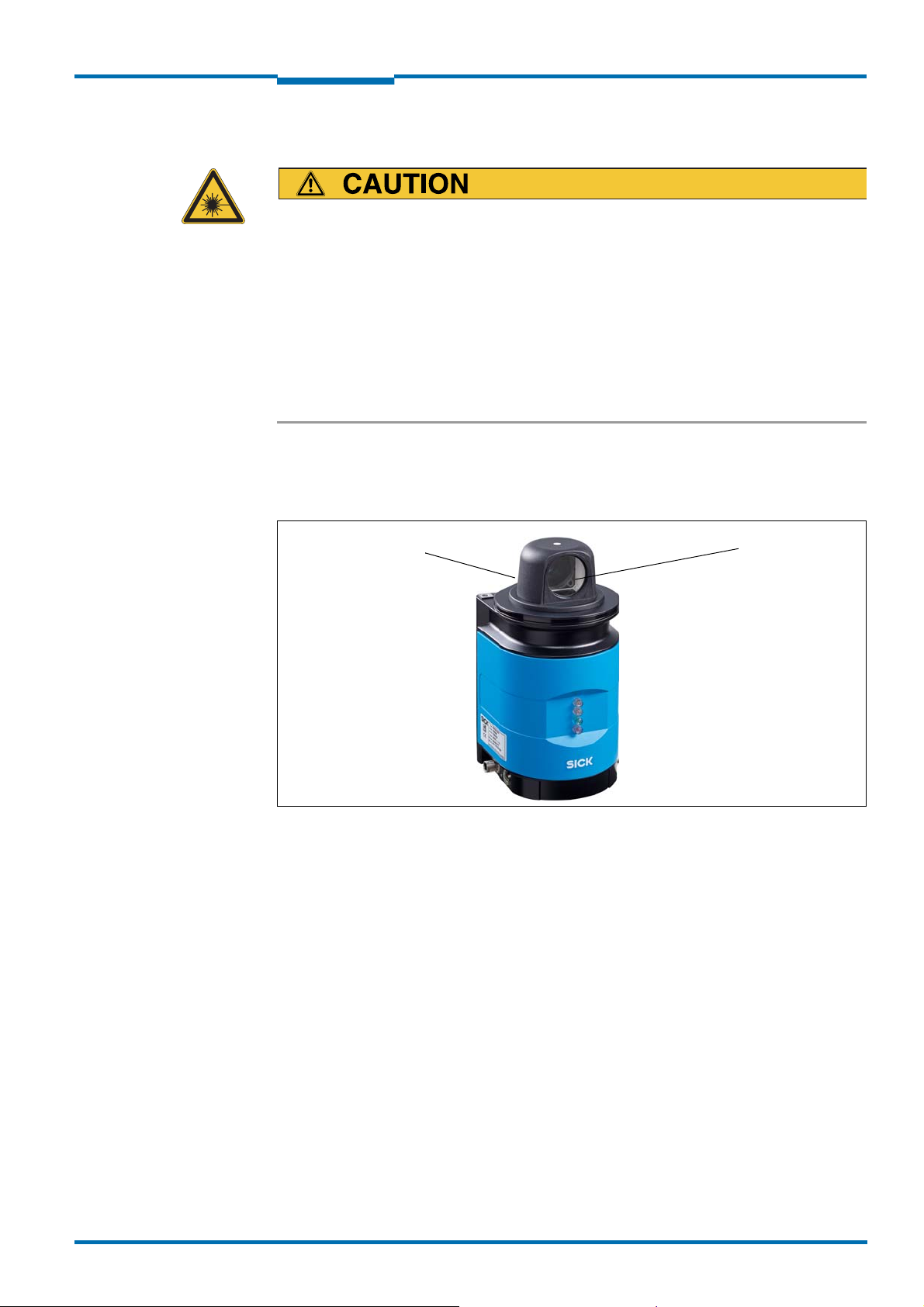
2.3.2 Laser radiation of the NAV350
Laser radiation!
The NAV350 is corresponds to laser class 1 (eye-safe) according
EN/IEC 60825-1:2014 (identical laser class for issue EN/IEC 60825-1:2007). Complies
with 21 CFR 1040.10 and 1040.11 except for deviations pursuant to Laser Notice No. 50.
The laser beam is not visible to the human eye.
• Improper use can lead to hazardous radiation exposure.
Do not open the housing (opening the housing does not prevent the laser
ing on).
Pay attention to the laser safety regulations as per IEC 60825-1 (valid version).
Important No maintenance is necessary to ensure compliance with laser class 1.
Laser output aperture
The laser output aperture is the view window on the scanner head of the NAV350.
to
Chapter 2
from switch-
8013889/ZML0/2017-06-09
Fig. 1: Laser output aperture on the NAV350
Laser power
The laser operates at the wavelength
λ = 905 nm (invisible infrared light). The radiation
emitted in correct use is not harmful to the eyes and human skin.
2.4 Quick stop and Quick restart
2.4.1 Switch the NAV350 off
Switch off the voltage supply (power supply) for the NAV350.
The NAV350 retains parameters stored in the internal, non-volatile memory. Measured values in the memory are lost.
2.4.2 Switch on the NAV350
Switch on voltage supply (power supply) for the NAV350.
The NAV350 restarts operation with the last saved parameters.
© SICK AG · Germany · All rights reserved · Subject to change without notice 13
Page 14

Chapter 2
For your safety
NAV350 Laser positioning sensor
Operating Instructions
2.5 Environmental protection
The NAV350 has been designed to minimise environmental impact. It uses only a minimum
of power.
While working, always act in an environmentally responsible manner. For this reason please
note the following information on disposal.
2.5.1 Power consumption
• The NAV350 consumes a maximum of 36 W in operation.
2.5.2 Disposal after final de-commissioning
Always dispose of unserviceable or irreparable devices in compliance with local/nation-
al rules and regulations on waste disposal.
Dispose of all electronic assemblies as hazardous waste. The electronic assemblies are
straightforward to dismantle.
Important SICK AG does not accept unusable or irreparable devices that are returned.
14 © SICK AG · Germany · All rights reserved · Subject to change without notice
8013889/ZML0/2017-06-
09
Page 15

Operating Instructions
NAV350
Product description
3 Product description
This chapter provides information on the special features and properties of the NAV350. It
describes the construction and the operating principle of the device, in particular the
different operating modes.
Please read this chapter before mounting, installing and commissioning the device.
3.1 Delivery
The NAV350 delivery includes the following components:
Quantity Component Comment
1 NAV350 Laser positioning sensor –
1 Device instructions with electrical circuit di-
1Lens cloth –
Tab. 3: Delivery
Chapter 3
Is included in the NAV350 packaging
agram for getting started
Source for obtaining additional
information
Additional information about the NAV350 and its optional accessories can be found in the
following places:
Product web page for the NAV350
(www.sick.com/NAV3xx)
• Detailed technical specifications (online data sheet)
• Technical information (supplementary information on telegrams for CoLa A/B,
part no.: 8016855 and USP, part no.:8016687)
• These operating instructions are available in German, English and other languages if re-
quired.
• Dimensional drawing and 3D CAD dimension models in various electronic formats
• EC declaration of conformity
• SOPAS configuration software updates
Support is also available from your sales partner: www.sick.com/worldwide.
8013889/ZML0/2017-06-09
© SICK AG · Germany · All rights reserved · Subject to change without notice 15
Page 16
Chapter 3
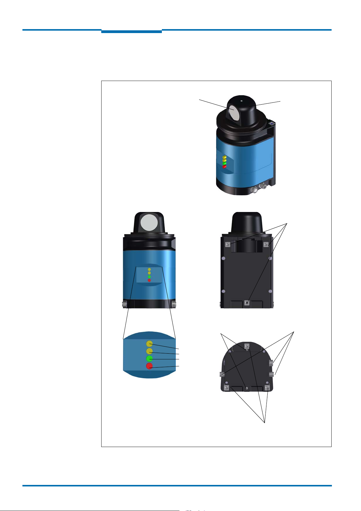
Fastening thread
M6×12
Fastening thread
M6×12
Laser output aperture
LEDs
Scanner head
Supply voltage
Ethernet
LEDs
Rear
Device connections
(M12 plug connectors)
Bottom
Yellow
Yellow
Green
Red
Alignment hole for
locating pin
Product description
3.2 Construction of the NAV350
3.2.1 Views of device
Operating Instructions
NAV350 Laser positioning sensor
Fig. 2: Views of device
16 © SICK AG · Germany · All rights reserved · Subject to change without notice
8013889/ZML0/2017-06-
09
Page 17

Operating Instructions
Yellow (1)
Yellow (2)
Green
Red
NAV350
Product description
Chapter 3
3.2.2 Controls and status indicators
User interface
The NAV350 operates fully automatically in normal operation without the intervention of an
operator.
The interactive configuration is carried out using the provided SOPAS ET configuration software. The software used for this purpose runs on a PC with the operating system Windows
that is connected to the NAV350 via one of the interfaces.
Use the graphic scan view in SOPAS ET to verify the generated measured values and to verify the measurement area online. During this process, note that SOPAS ET cannot display
the data in real-time and therefore does not display all measured values.
Status indicators
The LEDs signal the operational status of the NAV350.
The NAV350 has four LEDs. These visually signal the actual operational status and the sta-tus of the continuous self-check. The LEDs are on the front of the device on the NAV350.
tab. 4 shows the function of the LEDs.
Yellow
LED (1)
Off Off Off Off Device switched off.
On On On On LED test for 5 s after switching on.
Off On Any Any A command is being processed
Off Any Flashing
Off Any Flashing
Flashing 4 Hz
Any Any Any On System error in the device
Tab. 4: Meaning of the LED status indicators
Yellow
LED (2)
Off Flashing
Green LED Red
1Hz
4Hz
1Hz
Meaning
LED
No supply voltage.
The output signal switching device is active.
Any Stand by
Any Measurement mode
Off Firmware Update
For information on troubleshooting see
section 8.3 “Troubleshooting and rectification”
on page 61
8013889/ZML0/2017-06-09
© SICK AG · Germany · All rights reserved · Subject to change without notice 17
Page 18

Chapter 3
Product description
3.3 Special features of the NAV350
Special features Specific form
High performance
Safety and
convenience
Configuration/
operation
Result output Landmark detection
Electrical interfaces
• Usage on route with max. 12,000 reflectors
• Can be divided into up to 320 layers (as a result downward com-
patible with the NAV200)
• Detection of reflector marks in a scan angle of 360°
• Detection of reflector marks in the measuring range 0.5 m to 70
m (1.64 ft to 229.66 ft)
• Position measurement accuracy ±4 mm (0.16 in) to ±
(0.98 in)
(dependent on the average reflector distance)
• Contour measurement up to 35 m (114.83 ft) (for objects with a
remission of 10%)
• Angular accuracy ±0.1°
• Mounting orientation with optical axis parallel to the surface driv-
en over, overhead installation also possible
• Robust, compact metal housing (max. IP 65), CE marking
• Laser class 1
• Maintenance-free
• Configuration using SOPAS ET software for PC
• Alternatively using telegrams (command strings)
• Mapping (teach-in) of reflector positions
• Reflector measurement and output of the reflector position in the
local co-ordinate system of the NAV350
• Output of distance and angle of a reflector
• Optional: Output of distance, angle and remission value of the sur-
round-ing contour seen
Navigation
• Continuous position determination
• Output of the absolute position value of the NAV350 in a global co-
ordi-nate system
• Optional: Output of distance, angle and remission value of the sur-
round-ing contour seen
• Supply voltage DC 24 V
• Data interfaces: Ethernet, RS-232 serial
• 1 x output signal switching device for synchronisation
Operating Instructions
NAV350 Laser positioning sensor
25 mm
Tab. 5: Special features of the NAV350
18 © SICK AG · Germany · All rights reserved · Subject to change without notice
8013889/ZML0/2017-06-
09
Page 19
Operating Instructions
NAV350
Product description
Chapter 3
3.4 Applications
AGV line guidance based on contour and reflector measurements (mixed mode navigation):
• shuttle systems
• freely moving forklift
• truck loading
• general automated guided vehicles
3.5 Operating principle of the NAV350
The NAV350 has an opto-electronic laser measurement system that electro-sensitively
scans the contour of its surroundings in a plane with the aid of laser beams. The NAV350
measures its surroundings in two-dimensional polar coordinates. If a measurement beam
is incident on an object, the position is determined in the form of distance, direction and
remission.
8013889/ZML0/2017-06-09
Fig. 3: Measuring principle of the NAV350
From the propagation time that the light requires from emission to reception of the reflec-tion at the sensor the NAV350 calculates the distance to the object.
Scanning takes place in a sector of 360°. The scanner head rotates at a frequency of 8 Hz.
During this process, a laser pulse and therefore a distance measurement is triggered after
an angular step of 0.25°.
© SICK AG · Germany · All rights reserved · Subject to change without notice 19
Page 20
Chapter 3
Landmark detection
(output of reflector positions)
Navigation (output of absolute
position data)
Reflectors
Product description
NAV350 Laser positioning sensor
Operating Instructions
3.5.1 Navigation and landmark detection operating modes
The NAV350 has integrated application software that is used for the continuous detection
of reflectors. By means of the reflectors the absolute position of the NAV350 (section 3.7
“Navigation” on page 24), the relative position of the reflectors detected (section 3.6 “Landmark detection” on page 23) or a combination of both can be output to the vehicle comput-
er connected.
x = 2500
y = 2500
=45°
Fig. 4: Principle of operation of the NAV350
x = 1000
y = 2500
= 70°
In addition to navigation and landmark detection, the NAV350 can output the surrounding
contour measured to the vehicle computer connected (mixed mode).
20 © SICK AG · Germany · All rights reserved · Subject to change without notice
8013889/ZML0/2017-06-
09
Page 21
Operating Instructions
NAV350
Product description
Chapter 3
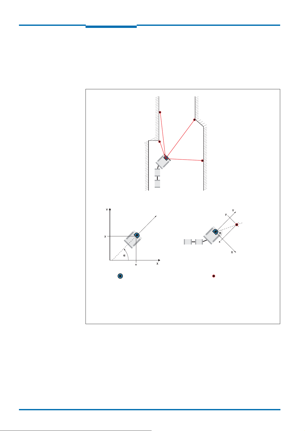
3.5.2 Influences of objects on the measurement
The majority of surfaces reflect the laser beam diffusely in all directions. The reflection of
the laser beam will vary as a function of the surface structure and colour. Light surfaces re-flect the laser beam better than dark surfaces and can be detected by the NAV350 over
larger distances. Brilliant white plaster reflects approx. 100% of the incident light, black
foam rubber approx. 2.4%. On very rough surfaces, part of the energy is lost due to shading.
The scanning range of the NAV350 will be reduced as a result.
Fig. 5: Diffuse reflection from objects
The reflection angle is the same as the angle of incidence. If the laser beam is incident per-pendicularly on a surface, the energy is optimally reflected (on the left). If the beam is inci-dent at an angle, a corresponding energy and scanning range loss is incurred (on the right).
Fig. 6: Directional reflection from reflectors
The incident radiation is not reflected diffusely in all directions by reflectors, but direction-ally. As a result a large portion of the energy emitted can be received by the NAV350. The
NAV350 makes use of this situation to be able to exactly measure the positions of reflec-tors.
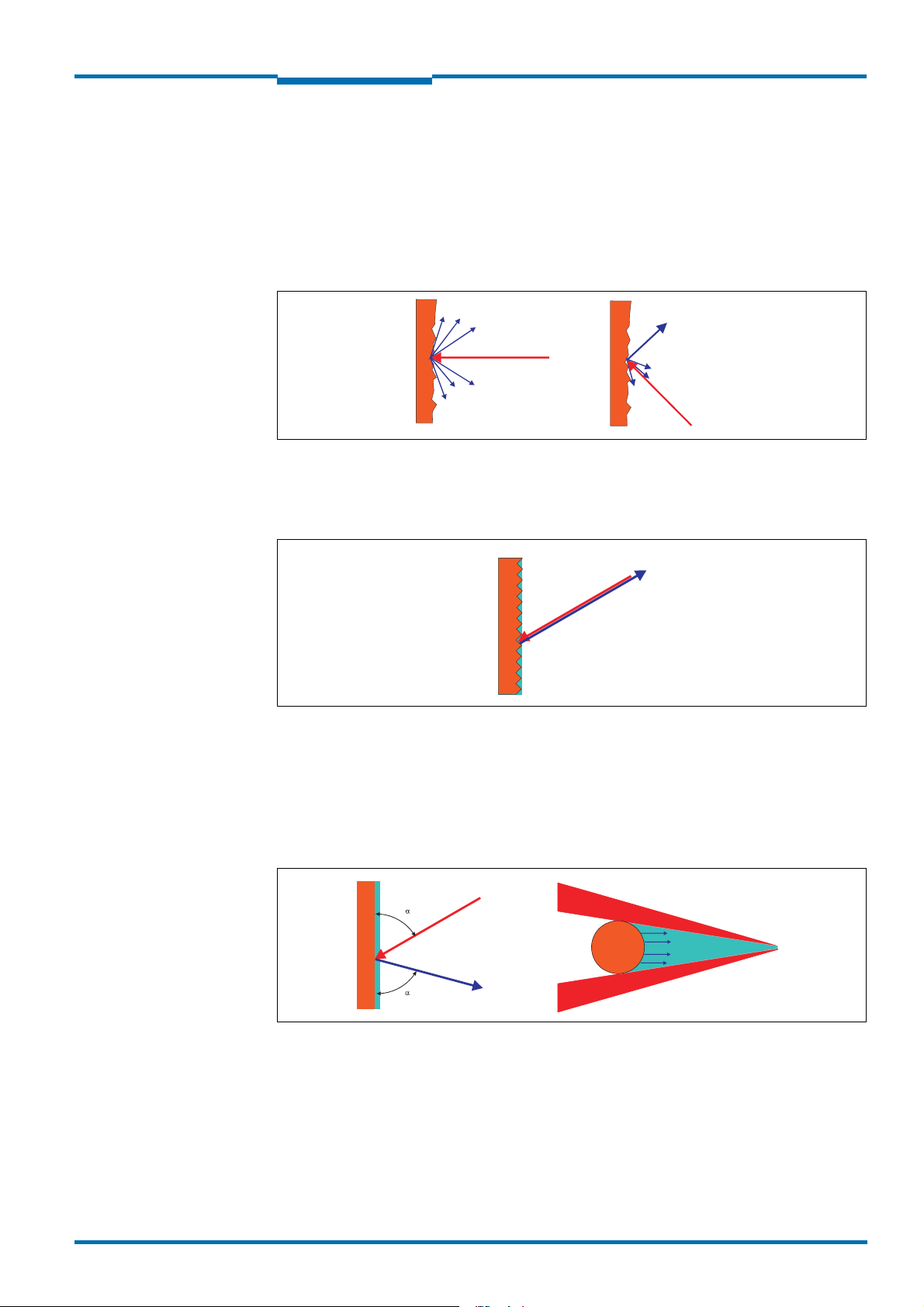
Possible sources of errors
Fig. 7: Possible sources of errors during the measurement
At mirror surfaces (fig. 7, on the left) the laser beam is almost entirely deflected. Instead of
the surface of the mirror, it is possible that the object on which the deflected laser beam is
incident may be detected.
Objects that are smaller than the diameter of the laser beam (fig. 7, on the right) cannot re-flect all the energy of the laser light. The energy in the portion of the laser light that is not
reflected is lost. This means that the scanning range is less than would be possible theoret-ically based on the surface of the object.
8013889/ZML0/2017-06-09
© SICK AG · Germany · All rights reserved · Subject to change without notice 21
Page 22

Chapter 3
0
Distance in m
Size in mm
20 40 80 100
0
200
Beam diameter
Distance between measured points
400
60
800
600
Product description
NAV350 Laser positioning sensor
Operating Instructions
3.5.3 Scanning range of the NAV350
The scanning range of the NAV350 is dependent on the remission of the objects to be de-tected. The better a surface reflects the incident radiation, the greater the scanning range
of the NAV350.
Material Remission Range
Black car paint, matt 5% 0.5 … 24 m (1.64 … 78.74 ft)
Black photographic cardboard,
matt
Grey concrete 18% 0.5 … 45 m (1.64 … 147.6 ft)
White cardboard 90% 0.5 … 100 m (1.64 … 328.1 ft)
White plaster 100% 0.5 … 110 m (1.64 … 360.9 ft)
Reflective tape >300% 0.5 … approx. 250 m (820.21 ft)
Tab. 6: Typical remissions and scanning ranges
10% 0.5 … 35 m (1.64 … 114.8 ft)
3.5.4 Beam diameter and distance between measured points
With increasing distance from the NAV350 the laser beam increases in size. As a result the
beam diameter on the surface of the object increases.
The distance-dependent beam diameter is the distance (mm (in)) × 0.005 rad + 20 mm
(0,79 in).
With increasing distance from the NAV350 the spacing between the individual measured
points also increases. The diagram in fig. 8 shows the beam diameter and the distance be-tween measured points as a function of the distance from the NAV350.
Fig. 8: Beam diameter and distance between measured points at 0 to 100 m
To reliably detect an object, a laser beam must be fully incident on it once. If the beam is
partially incident, less energy will be reflected by an object than necessary in some circum-stances (see fig. 7 on page 21).
How to calculate the minimum object size:
Beam diameter + distance between measured points = minimum object size
For beam diameter and distance between measured points as a function of the dis-
22 © SICK AG · Germany · All rights reserved · Subject to change without notice
tance from the NAV350 see the diagram in fig. 8.
8013889/ZML0/2017-06-
09
Page 23

Operating Instructions
x = 1000
y = 2500
= 70°a
NAV350
Product description
Chapter 3
Important In particular on the usage of the NAV350 for the output of measured values, it is necessary
for a reliable measurement that the beam is incident on the object several times.
3.6 Landmark detection
In the LANDMARK DETECTION operating mode the NAV350 generates an image of its current
reflector environment in one revolution of the scanner head.
The 40 most dense reflectors from up to 250 measured reflectors are taken into account
for positioning to limit the output size. These can be output by means of a telegram. The
NAV350 calculates the exact position from the next four to eig ht ref lect ors i n an as ymmet ric
arrangement. (see fig. 24 on page 40) The reflectors are selected adaptively.
Fig. 9: Landmark detection
This mode enables the AGV’s vehicle computer to directly access in real-time the landmark
coordinates (reflectors) measured by the NAV350. The data from this direct access can be
evaluated by the vehicle computer with the aid of specific algorithms to calculate the vehicle
position. This may be performed using data from other sensors, e.g., encoders.
8013889/ZML0/2017-06-09
© SICK AG · Germany · All rights reserved · Subject to change without notice 23
Page 24

Chapter 3
Product description
NAV350 Laser positioning sensor
Operating Instructions
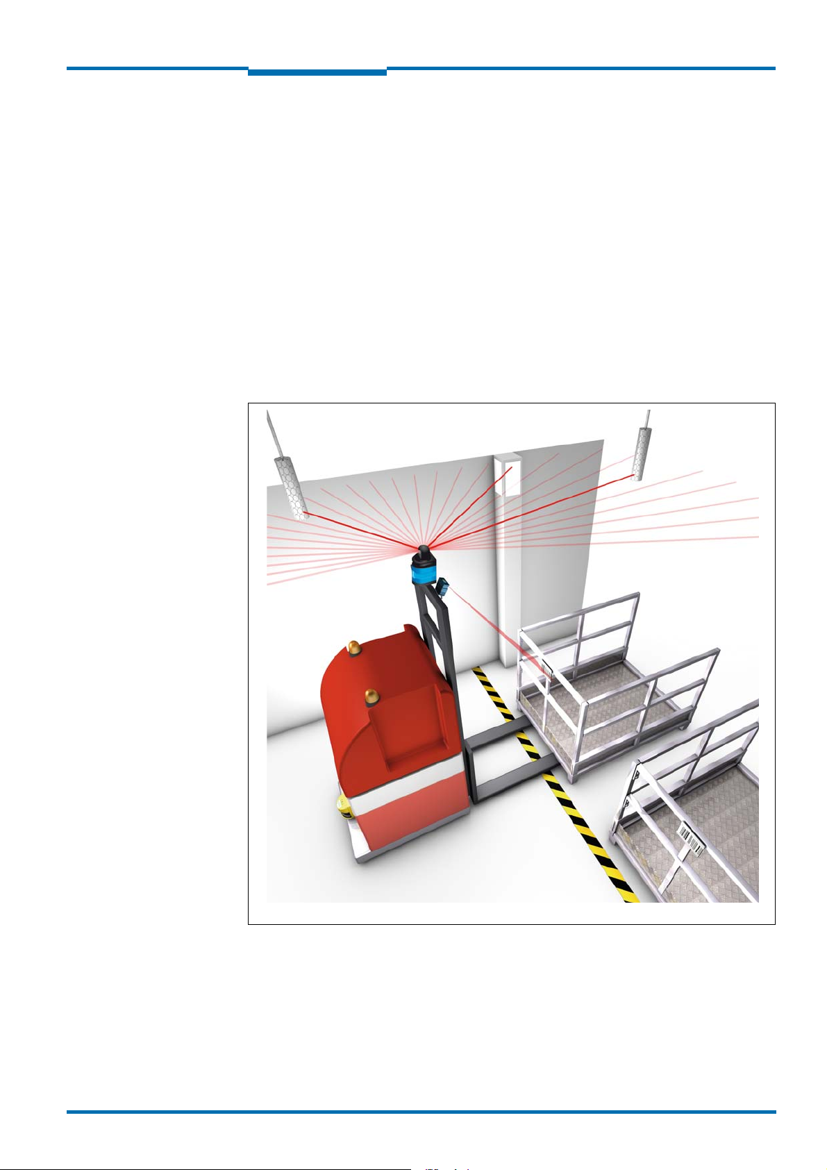
3.7 Navigation
In the NAVIGATION operating mode the NAV350 determines its own current position on the
route during the movement of the AGV. This action is performed based on reflectors positioned in fixed locations in the surroundings. The detection of three reflectors is sufficient
to determine the position.
Fig. 10: Determination of the position by the NAV350 by means of the detection of reflector
placements
For position output …
• an absolute coordinate system with an origin must be defined (as a rule in a corner
a building,
see section 3.10.4 “Absolute coordinate system” on page 38).
• reflectors must be fitted along the route (see section 3.10.6 “Reflector placements”
page
40). These reflector are either measured and their coor
NAV350 or
they are taught-in by the NAV350 (mapping).
dinates saved in the
of
on
The NAV350 passes the position data to the AGV’s vehicle computer on request. The vehicle
computer steers the AGV along the programmed and therefore pre-defined route and corrects any course deviations that occur with the aid of the NAV350.
3.7.1 Operating principle of the NAV350 during determining position
During position determination, the NAV350 has three operational statuses:
• initial positioning
• continuous positioning
• Virtual positioning
24 © SICK AG · Germany · All rights reserved · Subject to change without notice
8013889/ZML0/2017-06-
09
Page 25

Operating Instructions
r
Route
NAV350
Product description
Chapter 3
Initial positioning
After the transition from another operating mode (e.g. stand-by) to the N
AVIGATION operating
mode, the NAV350 calculates and identifies the reflector positions by making a pattern
comparison between the measured reflectors and the saved reflector positions in the current layer. Requirements for successful initial positioning are:
• The vehicle is not moving.
• There are at least three reflectors in the field of view of the NAV350.
Depending on the number of measured reflectors and number of reflectors in the current
layer, initial positioning can take several seconds.
If the last position is still known, using the software telegram
SMN MNPOSSETPOSE the vehi-
cle computer can directly activate continuous positioning from a defined position and in this
way restore the contact to the layer.
Continuous positioning
After successful initial positioning the NAV350 automatically changes to the continuous positioning operational status. Here the computationally intensive pattern comparison of the
initial positioning is not required. The NAV350can supply new position data with a repetition
rate of approx. 8 Hz.
During continuous positioning the NAV350 has an expectation as to the approximate position of the reflectors (see fig. 11). For this purpose the NAV350 places a detection window
with a configurable radius r (factory setting 300 mm (11.81 in)) around each reflector coordinate.
8013889/ZML0/2017-06-09
Fig. 11: Identification of reflectors in the operational status “continuous positioning”
Reflectors are measured within the identification window. The relevant reflectors are used
to calculate the position by means of the adaptive selection. By configuring larger detection
windows, the NAV350 can be optimised for instance for very dynamic AGV velocity changes,
by reducing the size of the windows for extreme conditions due to misreflections.
© SICK AG · Germany · All rights reserved · Subject to change without notice 25
Page 26

Chapter 3
dist in m
r in mm
Product description
NAV350 Laser positioning sensor
Operating Instructions
The radius of the detection window can also be configured as a function of the distance between the NAV350 and the reflector. For this purpose the start and end point of a linear
function and the size of the detection window at the start and end point are transferred to
the NAV350.
The minimum start point for the linear function at dist
imum end point at dist
can be at 70 m (229.66 ft). The radius of the detection window
High
can be at 0.5 m (1.64 ft), the max-
Low
can be set in the range from 100 … 2,000 mm (3.94 … 78.74 in).
Fig. 12: Radius of the detection window as a function of the distance
If position is lost due to disruptive factors (e.g. simultaneous coverage of several reflectors), the NAV350 initiates an initial positioning. If the last position is still known, using
the software telegram sMN mNPOSSetPose the vehicle computer can directly activate continuous positioning from a defined position and in this way restore the contact to the layer.
Virtual positioning
If the initial positioning fails, a position is estimated based on the entered speed and motion
model for max. 3 m. After 3 m, the virtual position estimate is stopped.
26 © SICK AG · Germany · All rights reserved · Subject to change without notice
8013889/ZML0/2017-06-
09
Page 27

Operating Instructions
r
max
r
min
NAV350
Product description
Chapter 3
Measurement quality as indicator for the reliability of the position data
Together with the position data, the NAV350 provides the measurement quality to the vehicle computer. The measurement quality evaluates the deviation between the saved reflector positions and the detected reflector positions. It is a relative measure for the reliability
of the position data. The measurement quality is output in millimetres as the standard deviations of all measured values for the reflectors detected per scan.
Errors in the measurement are output via the optional position data.
For further information on quality see document “NAV350 Telegram listing”, part no.:
8013893.
If large deviations occur between saved and detected reflector positions, it is recommended
to check the reflector placement and the velocity information, as well as to limit the acceleration of the AGV if possible.
The measurement quality has an effect on the control loop in the vehicle computer. Using
this information, the system integrator can determine to what extent the position data from
the odometry need to be corrected by the position data from the NAV350. The influence of
the position data from the NAV350 on the correction is application-specific and depends on
the quality of the odometry and the positioning tolerances allowed in the system.
3.7.2 Measuring accuracy
Positions in a restricted action radius of the NAV350 are measured more accurately and improve the positioning accuracy (see section 9.1 “Data sheet NAV350” on page 63).
Recommendation Mount the reflectors at docking stations (e.g. pallet transfer point) and on bends within the
defined, restricted action radius of the NAV350 or in relation to the route.
From the reflectors measured the NAV350 selects the 4 to 8 best distributed reflectors and
uses these reflectors to determine the position.
8013889/ZML0/2017-06-09
Fig. 13: Restricted action radius
© SICK AG · Germany · All rights reserved · Subject to change without notice 27
Page 28

Chapter 3
Product description
NAV350 Laser positioning sensor
Operating Instructions
Reduction of the action radius
The parameters for the minimum and maximum radius are set using a software telegram
from the vehicle computer. During this process it must be ensured that from every position
of the NAV350 at least 3 reflectors are visible within the restricted action radius. If, e.g.,
there are only 2 reflectors within the restricted action radius, the NAV350 switches automatically to the full action radius.
The example in fig. 13 shows a defined, restricted action radius with the parameters
r
= 500 mm (19.69 in) and r
min
= 15,000 mm (590.55 in) in which the NAV350 is de-
max
tecting five reflectors.
Sector muting
In certain applications it can be desirable to mute certain angular segments (sectors) within
the 360° scan range of the NAV350, e.g. if individual reflectors are partially obscured by a
raised load and therefore it is not possible to exactly determine the middle of the reflectors.
This situation can result in reduced accuracy during the position determination.
The NAV350 does not use any measurements from reflectors that are in completely or partially muted sectors for the position determination.
The muted sectors are set in the
NAVIGATION operating mode. The sector muting is then active
for the following position request. However, the setting cannot be saved.
Important The reflector layout is to be designed such that for the NAV350 at least three reflectors are
always visible in the sectors that are not muted.
If this is not the case, the NAV350 determines the position using all visible reflectors (similar
to the measuring accuracy, see section 3.7.2 “Measuring accuracy” on page 27) and outputs this condition in the
DIAGNOSTICS INFORMATION part of the telegram in the reply to the next
position request (see “NAV350 Telegram listing”, part no.: 8013893).
The limits for the muted sectors are stated as mathematically positively angles in mdeg. Up
to 4 sectors are possible. The sectors are not allowed to overlap and the starting angle must
be defined in ascending order that starts with a value ≥0.
28 © SICK AG · Germany · All rights reserved · Subject to change without notice
8013889/ZML0/2017-06-
09
Page 29

Operating Instructions
S
4
S
3
S
1
S
2
0°
<0.6°
Reflector 1
Reflector 2
NAV350
Product description
Chapter 3
Fig. 14: Example for the definition of muted sectors
3.7.3 How the NAV350 deals with sources of error
Overlapping reflectors
On driving around corners or in aisles, two reflectors positioned one after the other will time
and again partially or completely overlap from the point of view of the NAV350. The positions of these reflectors can then no longer be unambiguously defined and will make the
position calculation by the NAV350 incorrect. The NAV350 detects such a situation and automatically mutes the usage of the overlapping reflectors.
The situation of an overlapping reflector occurs if the angle between two reflectors from the
point of view of the NAV350 is less than 0.6°. The reflector placement is to be selected for
this case such there are at least 3 further reflectors in the field of view of the NAV350.
Fig. 15: Overlapping of two reflectors
8013889/ZML0/2017-06-09
© SICK AG · Germany · All rights reserved · Subject to change without notice 29
Page 30

Chapter 3
300 mm 300 mm
Product description
NAV350 Laser positioning sensor
Operating Instructions
Misreflections
Misreflections can be produced by highly reflective objects. Highly reflecti ve objects are, for
example: windows, stainless steel trim panels or metal pipes. The misreflections are produced if the measurement beam from the NAV350 is incident perpendicularly on these objects.
Fig. 16: Minimum distance from reflectors to other reflecting objects
So that these misreflections are not interpreted as reflectors, it is to be ensured the reflectors fitted are always at least 300 mm (11,81 in) from these objects. If the minimum distance cannot be maintained for specific objects, these objects are to be covered using a
material with low reflection properties.
Subsequent movement of reflectors
Movement of reflectors that are also still in the measurement area of the NAV350 after they
have been moved, will make the result of the measurement incorrect and must be corrected.
For correction the reflector must be returned to its original position or the coordinates of the
new reflector position must be measured using the M
APPING function and transferred to the
NAV350 using SOPAS ET.
Subsequent removal or obscuring of reflectors
If reflectors are obscured or removed, the NAV350 continues to determine its position
based on the remaining reflectors without interruption, as long as at least three reflectors
are visible from the position of the scanner head.
30 © SICK AG · Germany · All rights reserved · Subject to change without notice
8013889/ZML0/2017-06-
09
Page 31

Operating Instructions
NAV350
Product description
Chapter 3
3.8 Output of measured values
In addition to navigation and landmark detection, the NAV350 can output the measured
surrounding contour to the host connected (mixed mode).
The measured values can be transmitted to a computer system connected and evaluated
here (see section 3.9.2 “Data communication using telegrams” on page 32). The host can
calculate the position of the AGV from these measured values.
Navigation based on the surrounding contour measured is useful in places in which it is not
possible to attach any reflectors, for example in truck cargo bays.
Fig. 17: Output of measured values for truck loading
The NAV350 outputs the following measured values at its data interfaces:
• profile of the field of view in two-dimensional polar coordinates
• contents of one revolution (360°): among other data, starting angle for the scan, st
wi
dth, time stamp for start of the scan, number of measured values, value and direction
of the measured distance, remission value of the object measured
Important It is only possible to output all measured values of a 360° scan in real-time using the Ether-
net interface.
ep
3.9 Integration of the NAV350 in an AGV’s control system
Recommendation The integration of an NAV350 in an AGV’s control system requires sound programming skills
in the area of vehicle control. In addition knowledge of the data exchange between a laser
positioning sensor such as the NAV350 and the vehicle computer are required. We therefore strongly recommend you make use of the training offered by SICK AG on the Hamburg
site.
3.9.1 Data interfaces
The NAV350 has a serial host interface and an Ethernet interface. The NAV350 is configured with the aid of SOPAS ET via these interfaces. The NAV350 also communicates with
the AGV’s vehicle computer via its interfaces.
8013889/ZML0/2017-06-09
© SICK AG · Germany · All rights reserved · Subject to change without notice 31
Page 32

Chapter 3
Answer
sAN mNPOSGetPose (absolute position)
or: sAN mNLMDGetData (landmark positions)
Request
sMN mNPOSGetData (absolute position)
or: sMN mNLMDGetData (landmark positions)
Product description
NAV350 Laser positioning sensor
Operating Instructions
3.9.2 Data communication using telegrams
The NAV350 sends telegrams over the interfaces described above to communicate with a
connected vehicle computer. The following functions can be run using telegrams:
• setting parameters by the AGV’s computer for the configuration of the NAV350
• querying parameters and status logs by the AGV’s computer
• requesting landmark positions (if necessary incl. the contour measured values) by
V’s computer, subsequent answer NAV350
AG
the
• requesting positions (if necessary incl. the contour measured values) by the AGV’s com-
puter, subsequent answer NAV350
Fig. 18: Requesting an absolute position or landmark positions
Depending on the frequency of the data request from the vehicle computer, the NAV350
transfers data to the vehicle computer up to eight times per second.
The telegrams each comprise a frame (see section “Frame and coding for the telegrams”
on page 32) and the data.
Frame and coding for the telegrams
Frame Telegram Frame
Designation
Length (byte)
4Description
Tab. 7: Frame for the telegrams with ASCII coding
Start of text character ASCII coded. The length is dependent on the previous
STX Data (see “NAV350 Telegram listing”, part no.:
1 ≤35 kB 1
A detailed description of the different telegrams can be found in the “NAV350 Telegram listing”, part no.: 8013893.
ETX
8013893)
End of text character
send telegram.
32 © SICK AG · Germany · All rights reserved · Subject to change without notice
8013889/ZML0/2017-06-
09
Page 33

Operating Instructions
NAV350
Product description
Chapter 3
3.9.3 Relative position system and absolute position system
The AGV uses two position systems for vehicle control: a relative position system and an absolute position system.
The relative position system takes its data from the odometry (incremental encoder). The
odometry supplies new data with a high refresh rate; the vehicle computer can calculate the
position of the vehicle from these data. However, the relative position calculation includes
errors. The error increases the greater the distance covered.
The absolute position system NAV350 on the other hand supplies absolute position data
on the route. Based on these absolute positions the AGV’s vehicle computer can minimise
the errors from the odometry.
fig. 19 shows schematically the integration of the NAV350 in a complete navigation system:
Fig. 19: Integration of the NAV350 in a navigation system
Overview of the integration of the NAV350 in the control system for an AGV
The vehicle computer informs the NAV350 of the actual velocity and rate of turn of the AGV
from its odometry (see fig. 18 on page 32). To optimise the control, the vehicle computer
transmits the velocity to the NAV350 several times between two position requests. The
NAV350 uses the velocity data for three calculations:
• From the velocity data an expected position for reflectors in the next measuring cycl
c
alculated, in this way the measurement of the reflectors within one head revo
corrected (
see fig. 11 on page 25).
lution is
• Calculated position data are extrapolated to the time of the data transfer.
• By transferring the velocity several times between two position requests the NAV3
c
alculates a movement profile so as to take into account large AGV movement chan ges.
Important If no velocity data are transferred to the NAV350 by the vehicle’s control system, the
NAV350 calculates internally the velocity between two positions determined. This determination of the velocity can only be used at low accelaration and is only suitable for test purposes. For practical operation the velocity must be provided by the vehicle’s control system.
The velocity and the rate of turn of the AGV must be transformed to the position of the
NAV350 on the AGV.
e is
50
8013889/ZML0/2017-06-09
© SICK AG · Germany · All rights reserved · Subject to change without notice 33
Page 34

Chapter 3
128 ms
Product description
NAV350 Laser positioning sensor
Operating Instructions
3.9.4 Digital output
The NAV350 has a digital output that is used for the synchronisation of the internal clock
on the NAV350 and the vehicle computer’s clock. The output supplies a 10 or 128 ms long
pulse depending on the synchronisation method (see section 3.9.5 on page 34). The pulse
is output dependent on the synchronisation method.
Fig. 20: Pulse for synchronisation
3.9.5 Synchronisation of the clock in the AGV and the clock in the NAV350
For precise control, it is necessary to synchronise as accurately as possible the navigation
data and landmark data from the NAV350 and the calculations on the vehicle computer.
The internal time stamp in the NAV350 is added to the measured data from the NAV350.
The internal time stamp in the NAV350 is a 32-bit counter that counts up by 1 every 1 ms.
To synchronise the internal time in the NAV350 with the system time in the vehicle’s control
system, the NAV350 provides three options.
1. via telegram
The vehicle computer requests the internal time from the NAV350 using a telegram
e NAV350 writes its internal time in a telegram and sends it to the vehicle computer
Th
Ho
wever, there can be a delay of up to 3 ms on sending the data, as a result there
certain amount of inaccuracy.
2.
via telegram and comparison with the digital output on the NAV350
The vehicle computer request the internal time from the NAV350 using a telegram.
hardware
tim
the veh
ta between the pulse and the reception. As a result the AGV can determine the ac
tim
output supplies a pulse of at least 10 ms in length as
e stamp is written to the telegram. When the telegram is subsequently re
soon as the internal
ceived by
icle computer, the vehicle computer can add to the time in this telegram the del-
e in the NAV350.
tual
3. based on pulses on the hardware output
The parameters for the hardware output are set using a telegram to generate, based on
the 32-bit counter, an output pulse of 128 ms in length in a fixed cycle. The configuration is set using a bit pattern from bit 10 … 20. Depending on the bit set, an output
pulse is generated when this bit overflows in the counter.
A configuration of e.g. 15 bit generates an output pulse every 32,768 ms
When the
pulse arrives, the vehicle computer knows that in the NAV350 the 14 least
.
significant bits of the counter are 0. Based on the time stamp in the telegram received
subsequently, the vehicle computer can now determine the time that has elapsed since
the telegram and add it to the time in the telegram.
Important Program the vehicle’s control system such that it reacts to the rising edge of the output
pulse
.
.
is
The
34 © SICK AG · Germany · All rights reserved · Subject to change without notice
8013889/ZML0/2017-06-
09
Page 35

Operating Instructions
NAV350
Product description
Chapter 3
3.9.6 Result Port
The NAV350 features a Result Port, a simplyfied telegramme with its own port. The Result
Port supplies landmark data and scan data parallely to the CoLa dialect.
The Result Port can be configured via the SOPAS user interface. Alternatively, the Result
Port may also configured using the CoLa diagrammes.
8013889/ZML0/2017-06-09
© SICK AG · Germany · All rights reserved · Subject to change without notice 35
Page 36

Chapter 3
Product description
NAV350 Laser positioning sensor
Operating Instructions
3.10 Planning
3.10.1 System requirements of the NAV350
For commissioning and operating the NAV350, the following are required at the user:
• Supply voltage DC 24 V ±15 %, generated as per IEC 60 364-4-41 (VDE 0100, part 410),
output power minimum 40 W (see section 5.3.1 “Supply voltage” on page 46)
• Standard Intel Pentium PC or compatible, at least Pentium III, 500 MHz
– RAM: minimum 256 MB, 512 MB recommended
– operating system: MS Windows 2000, XP, VISTA or 7
– monitor: minimum 256 colours, 65,536 colours recommended;
Screen resolution a
– hard disc: minimum 220 MB free memory
– data interface RS232 or Ethernet (see section 5.3.3 “General conditions for the data
interface” on page 47), if necessary RS232 converter, if PC interface and interface on
the NAV350 do not match
t least 800×600
3.10.2 Mounting requirements
The NAV350 must be mounted stable.
For the NAV350 the mounting kit part no. 5311055 with mounting material is available.
As an alternative you can use a strong stable mounting bracket that provides adjustable
alignment of the NAV350 in the X- and Y axis. The NAV350 weighs approx. 2.4 kg (5.29 lb).
36 © SICK AG · Germany · All rights reserved · Subject to change without notice
8013889/ZML0/2017-06-
09
Page 37

Operating Instructions
Safety supplement
5 mm/m (0.061 in/ft)
Safety supplement
5 mm/m (0.061 in/ft)
198 mm
(7.8 in)
Optical axis
Expanding
laser beam
Distance
NAV350
Product description
Chapter 3
3.10.3 Distance between NAV350 and the object/surface to be measured
The measurement area on the NAV350 starts at 0.5 m (1.64 ft) in front of the optics (light
output window).
To prevent false measurements, in the case of the recessed installation of the NAV350 the
increase in the size of the laser beam with increasing distance is to be taken into account.
If mounted poorly, objects in the scan range may be continuously detected as the laser
beam is always incident on them.
Fig. 21: Increase in the size of the beam and safety supplement
The optical axis is used as the reference plane for the distance to be maintained from the
wall; on the vertically mounted NAV350 this axis is approx. 198 mm (7.8 in) above the bot-tom edge of the housing.
The distance-dependent increase in the size of the beam can be calculated using the
formula:
beam diameter = (distance (mm (in)) × 5.0 mrad) + 20 mm (0.79 in)
1)
The following table shows a few values as examples:
Distance in m
Beam diameter [mm]
Tab. 8: Beam diameter at different distances from the NAV350
5 10 15 20 25 30 40 50 60 70
45 70 95 120 145 170 220 270 320 370
For the assessment of whether the laser beam can be incident on an object, the distance
of half the beam diameter from the optical axis is used.
Important Use a safety supplement of 5 mm (0.2 in) per metre top and bottom (see fig. 21 on
page 37).
Recommendation For the simplified calculation of the sum of the increase in the size of the beam and safety
supplement, a value of 16 mm (0.63 in) per metre can be used.
8013889/ZML0/2017-06-09
1) Due to the transmit lens.
© SICK AG · Germany · All rights reserved · Subject to change without notice 37
Page 38

Chapter 3
NAV350
Product description
NAV350 Laser positioning sensor
Operating Instructions
3.10.4 Absolute coordinate system
During the planning of the reflector positions, a common coordinate system is defined on a
floor plan. This absolute coordinate system corresponds to the coordinate system of the in-
dustrial machine/system. In this way the origin and axes for the absolute coordinate systems are defined.
In this coordinate system the NAV350 determines its absolute position in the X and Y direction including the angular position α of its local coordinate system in relation to the absolute coordinate system. The angular position here is the angle between the X axis of the
sensor and the X axis of the absolute coordinate system. The angles are mathematically
positive in the counterclockwise direction.
Fig. 22: Absolute and local coordinate system with angular position of the NAV350
X, Y = Absolute coordinate system of the machine/system
x, y = Local coordinate system of the NAV350
Direction of the NAV350 in the absolute coordinate system
=
α
The coordinate origin for the NAV350 is on the axis of the scanner head.
3.10.5 Reflectors
The NAV350 allocates the measured data determined from its surroundings to the reflector
positions saved. For this purpose it must differentiate the reflectors from other reflecting objects. The NAV350 checks the measured data using characteristic data that are saved in its
memory. These characteristic data apply to the reflective tape 983-10 (part no. 5320565)
that is available as an accessory from SICK AG under the designation REF-DG.
Important Reflective tapes of other makes may not be correctly detected by the NAV350.
The reflector markers are designed as cylindrical reflectors. Cylindrical reflector markers
can be detected from any angle.
38 © SICK AG · Germany · All rights reserved · Subject to change without notice
8013889/ZML0/2017-06-
09
Page 39

Operating Instructions
0
Distance in m
Size in mm
20 40 80 100
0
200
Reflector height
400
60
800
600
1000
NAV350
Product description
Chapter 3
Reflector height
The vertical size and the vertical position of the reflectors are to be chosen such that the
measurement beam is incident on the reflector even on an uneven floor. The maximum
scanning range of the NAV350 is 70 m (229.66 ft) onto reflectors. It is possible to determine the minimum reflector heights based on the characteristics of the floor and the measurement distance. The measurement beam on the NAV350 increases in size by around
5 mm (0.63 in) per metre measurement distance (see 3.10.3 on page 37). Tipping of the
AGV due to unevenness on the floor must be taken into account as appropriate (incl. safety
supplement). Recommended reflector heights are 500 mm (19.69 in) for a measurement
distance up to 30 m (98.43 ft), 750 mm (29.53 in) for a measurement distance up to 46 m
(150.92 ft) and 1000 mm (39.37 in) for a measurement distance up to 70 m (229.66 ft).
Fig. 23: Reflector height as a function of the distance from 0 to 70 m
Important The values stated in fig. 23 apply without taking into account unevenness on the ground
and tipping of the AGV by the load!
reflector diameter
The recommended diameter of cylindrical reflectors is 80 mm (3.15 in). If the diameters of
the reflectors differ, it can lead to deviating measurement characteristics. Within a layer the
diameter of cylindrical reflectors can vary. However, if it is intended to map the entire layer,
only reflectors with the same diameter may be used.
Reference points for the reflectors
To unambiguously determine the coordinates of a reflector using the NAV350, the surface
of the reflector must be reduced to a reference point:
In the case of cylindrical reflectors the reference point is at the intersection between the vertical axis of the cylinder and the scan plane, which in general is at half the height of the reflector.
8013889/ZML0/2017-06-09
© SICK AG · Germany · All rights reserved · Subject to change without notice 39
Page 40

Chapter 3
Product description
NAV350 Laser positioning sensor
Operating Instructions
3.10.6 Reflector placements
Reflector placements are to be planned such that the NAV350 has a clear view of at least
3 reflectors in every position. A clear view of 4 to 5 reflectors is recommended to ensure
reliable positioning even in the case of the operation of several AGV. As far as possible the
same number of reflectors should be fitted to both sides of the route.
The NAV350 identifies a reflector placement by allocating individual reflector position
measurements to the reflector coordinates saved. Specific requirements must be taken
into account for the reflector placement for the initial positioning. So that the NAV350 can
clearly unambiguously identify a reflector placement during the initial positioning (see “Ini-
tial positioning” on page 25), it needs a certain pattern in the placement. In such pattern,
all the distances between the reflectors vary by at least 500 mm (19.69 in).
fig. 24 shows two examples for a correct and an incorrect reflector placement.
Fig. 24: Correct, asymmetrical placement and incorrect, symmetrical placement of reflectors
During continuous positioning (see “Continuous positioning” on page 25) the NAV350 can
also process symmetrical reflector placements.
40 © SICK AG · Germany · All rights reserved · Subject to change without notice
8013889/ZML0/2017-06-
09
Page 41

Operating Instructions
NAV350
Recommendation • As not all reflectors are detected during the journey or can be obscured for a time, more
Product description
Chapter 3
than 3 reflectors are always to be used per layer. Five reflectors are recommended. The
vehicle’s route is to be checked to ensure that at least 3 reflectors can be detected at
the same time.
• As far as possible the same number of reflectors is to be fitted to both sides of the route.
If the reflectors are only on one side as seen from the NAV350, the positioning accuracy
may be reduced by unfavourable geometrical conditions.
• At positions at which very high accuracy is required and on bends, as far
there m
betw
ust be 4 or more reflectors within the action radius of NAV350. Also
een 2 reflectors must not be more than 120°.
as possible
the angle
• At positions at which the NAV350 is placed on the route, there must be at least 4 to 6
reflectors in the measurement area of the NAV350. Also the angle between 2 reflec
must not be more
than 120°.
tors
In practice the recommendations stated cannot always be implemented. For this reason the
reflector positions must be planned as well as possible in relation to these recommendations.
3.10.7 Measurement and entry of the reflector coordinates
After planning and installation of the reflectors, the reflector coordinates must be measured
precisely. The NAV350 requires these coordinates for the determination of the position in
real-time. The coordinates of the reflectors used are saved in the non-volatile reflector memory in the NAV350 for reference.
There are two methods of measuring and entering the coordinates:
• A surveyor manually measures the positions of all reflectors referred to a common co-
ordinate system. All these coordinates are added to a structured ASCII file on the
and transferr
ed with the aid of the SOPAS ET configuration software to the NAV350 (see
PC
section 6.6 “Loading reflector data” on page 57). This transmission can also be made
from the vehicle computer using the software telegram A
(
SMN MNLAYADDLANDMARK).
• Using the M
NAV350 can also automatically
APPING function and then ADD LANDMARKS (SMN MNLAYADDLANDMARK) the
teach-in the reflector positions. For this purpose the
NAV350 requires exactly measured initial positioning so that then it can measure
oordinates of all reflectors on the route in succession.
c
DD LANDMARKS
the
Recommendation The determination of the reflector positions by a surveyor is more precise and will ensure
higher system accuracy.
APPING function of the NAV350 is suitable
The M
8013889/ZML0/2017-06-09
© SICK AG · Germany · All rights reserved · Subject to change without notice 41
Page 42

Chapter 3
Layer 1
Layer 2
Switch over points
1 m (3.28 ft)
Product description
NAV350 Laser positioning sensor
Operating Instructions
• for measuring new reflectors after initial installation.
• for correcting position changes on the reflectors.
• if only low positioning accuracy is required in the layer/in the system.
• if quick setup is required, e.g. at trade shows and exhibitions.
Division of the route into layers
The reflector data saved in the NAV350 can be allocate d to up t o 320 la y ers in g roups . Each
layer represents a fixed defined area in the AGV’s overall route through which the AGV passes. By switching over to the related layer, the NAV350 always only uses for detection the
reflector data for the related area through which the vehicle is passing. The switching over
between the layers is undertaken by the vehicle computer depending on the location.
Division into layers is used to …
• keep the NAV350 downward compatible with the NAV200.
• configure a large route more clearly.
A layer must be setup such that the NAV350 can detect as many reflectors as possible in
this layer, but as few reflectors as possible in other layers.
Fig. 25: Common usage of the reflectors from two neighbouring layers
Ideally the transitions between the layers are to be checked such that they take place on
straight sections of the route. The required switch over by the NAV350 from the reflector
data saved for one layer to the data for the neighbouring layer by the vehicle computer
should take place in the middle of a section around 1 m (3.28 ft) long.
Recommendation One and the same reflector can be allocated to two different layers. Layers can therefore
overlap, a feature that is recommended for a smooth AGV transition between two layers.
42 © SICK AG · Germany · All rights reserved · Subject to change without notice
8013889/ZML0/2017-06-
09
Page 43

Operating Instructions
NAV350
4 Mounting
Important Do not open the housing for the NAV350. If the housing is opened, any warranty claims
Mounting
against SICK AG will be rendered void.
4.1 Overview of the mounting steps
• select mounting method for the NAV350
• mounting and adjusting the NAV350
4.2 Preparations for mounting
4.2.1 Components to be mounted
• NAV350 (weight approx. 2.4 kg (5.29 lb)
4.2.2 Material and accessories necessary
• Fixing bracket by the user:
– Stable mounting bracket that provides adjustable alignment of the NA
an
d Y axis
– 3 screws M6 for the NAV350, screw length dependent on the wall thickness of the fix-
ing bracket used
V350 in the X
Chapter 4
4.3 Mounting and adjustment of the device
Risk of damage to the device!
The maximum screw length in the M6 blind threaded hole is 12 mm (0.47 in). Longer
screws will damage the NAV350.
Use screws of suitable length.
The NAV350 has three M6 blind thread holes and is fastened using 3 M6 screws (see
section 9.2.1 “Dimensional drawing NAV350” on page 65).
For secure mounting at least 3 M6 screws with washers and locking washers are required.
The supply of power must be switched off.
The NAV350 can be fitted in any position.
1. Prepare surface from mounting the fixing bracket for the NAV350 as described
tion 4.2 “Preparations for mounting” on page 43.
sec
2. Insert screws in the holes in the bracket and screw into the blind threaded ho
NAV350. Only tig
3. The scanner head on the NAV350 must be free to rotate.
4. Align the NAV350.
5. Tighten screws.
6. Check the alignment.
hten screws lightly.
in
le in the
8013889/ZML0/2017-06-09
© SICK AG · Germany · All rights reserved · Subject to change without notice 43
Page 44

Chapter 4
Mounting
NAV350 Laser positioning sensor
Operating Instructions
4.4 Dismantling the NAV350
1. Switch off the supply voltage.
2. Remove the connection cables.
3. Undo screws for mounting the NAV350 to the fixing and remove device.
44 © SICK AG · Germany · All rights reserved · Subject to change without notice
8013889/ZML0/2017-06-
09
Page 45

Operating Instructions
“RS232” connection
M12×8, plug
“Power” connection
M12×5, plug
“Ethernet” connection
M12×4, socket
NAV350
Electrical installation
5 Electrical installation
Only authorised personnel are allowed to perform the electrical installation work.
Do not open the housing.
Observe the current safety regulations when working on electrical systems.
Switch the entire machine/system offline!
The machine/system could inadvertently start up while you are connecting the device.
Ensure that the entire machine/system is disconnected during the electrical installa-
tion.
5.1 Overview of the installation steps
1. Wire switching outputs (application-dependent).
2. Temporarily connect PC (configuration).
3. Wire data interface for operation.
4. Connect supply voltage to the NAV350.
Chapter 5
5.2 Connections of the NAV350
5.2.1 Connections of the NAV350
Fig. 26: Connections of the NAV350
The NAV350 has three round multi-pin M12 plug connectors.
8013889/ZML0/2017-06-09
© SICK AG · Germany · All rights reserved · Subject to change without notice 45
Page 46

Chapter 5
4
2
3
5
1
2
1
8
7
65
4
3
Electrical installation
“Power” connection M12×5, plug, A coded
Pin Signal Function
1V
2V
3GND Ground
4 OUT 24 V Digital output 1
5GND Ground
Tab. 9: Pin assignment of the “Power” connection on the NAV350
S
S
“Ethernet” connection M12×4, socket, D coded
Operating Instructions
NAV350 Laser positioning sensor
Supply voltage NAV350
Supply voltage NAV350
2
1
Tab. 10: Pin assignment of the “Ethernet” connection on the NAV350
3
4
Pin Signal Function
1 Ethernet_TX+ Ethernet interface
2 Ethernet_RX+ Ethernet interface
3 Ethernet_TX– Ethernet interface
4 Ethernet_RX– Ethernet interface
“RS232” connection M12× 8, plug, A coded
Pin Signal Function
1 RxD Serial RS232 host interface (receiver)
2 TxD Serial RS232 host interface (sender)
3– Do not use
4– Do not use
5 GND RS-232 Ground RS-232
6– Do not use
7– Do not use
8– Do not use
Tab. 11: Pin assignment of the “RS232” connection on the NAV350
5.3 Preparing the electrical installation
5.3.1 Supply voltage
DC 24 V ±15% as per IEC 60 364-4-41 (pay attention to permitted cable lengths in tab. 12
on page 47)
The NAV350 draws the following power:
• on switching on without switching outputs wired maximum 36 W
• in operation typically 12 W, plus a maximum of 12 W with switching output wired
The supply of power/the external power supply for the supply of power must be able to
provide at least 40 W continuous power, if the switching output is wired at least 48 W
continuous power.
46 © SICK AG · Germany · All rights reserved · Subject to change without notice
8013889/ZML0/2017-06-
09
Page 47

Operating Instructions
NAV350
Electrical installation
Chapter 5
Use safety transformer!
The output circuit of the power supply must be safely electrically isolated from the input
circuit, this feature is normally provided by a safety transformer in accordance with IEC 742
(VDE 0551).
5.3.2 Wire cross-sections
Wire all connections with copper cables!
Use the following wire cross-sections:
– supply voltage at least 0.25 mm² (0.01 in²), if local supply of power (power
the imme
diate vicinity
supply) in
– supply voltage at least 0.5 mm² (0.04 in²) at maximum length of 10 m (32.81 ft), if
connection is made to an existing DC 24 V supply
– data interface minimum 0.25 mm² (0.01 in²)
Lay all cables such that there is no risk of tripping and all cables are pr
otected against
damage.
On t
he usage of a typical power supply with a nominal voltage of DC 24 V ±5%, the following
maximum cable lengths are allowed for the supply of the operating voltage:
Wire cross-section Cable length
0.25 mm² (0.01 in²) 5 m (16.4 ft)
0.5 mm² (0.02 in²) 10 m
Tab. 12: Maximum cable lengths for the supply voltage
5.3.3 General conditions for the data interface
The table below shows the recommended maximum length of cable.
Interface type Transmission rate Maximum cable length
RS-232 115,200 Bd 10 m
Tab. 13: Maximum length of cable for the data interface
Important • Use screened cable (twisted-pair) with at least 0.25 mm² (0.01 in²).
• To prevent interference, do not lay data cable in parallel with power
c
ables over a long run, e.g. in cable ducts.
5.4 Undertaking electrical installation on the NAV350
5.4.1 Equipment
• tool set
• digital multimeter (current/voltage measurement)
supply and motor
8013889/ZML0/2017-06-09
Only connect in electrically isolated state!
Ensure the power supply to which the NAV350 is connected is switched off.
© SICK AG · Germany · All rights reserved · Subject to change without notice 47
Page 48

Chapter 5
SICK AG | Waldkirch | Germany | www.sick.com
M12×5
Black = OUT1
Brown = V
s
Part no. 6043440, 5 m
Socket
Grey = GND
White = V
s
Blue = GND
DC 24 V
M12×4
RJ45
8 pin
Plug
Part no. 6034415, 5 m
Part no. 6030928, 10 m
Part no. 6036158, 20 m
Plug
PC
Electrical installation
NAV350 Laser positioning sensor
Operating Instructions
5.4.2 Connecting supply voltage
Pre-assembled cables with flying leads are available for the supply to the NAV350.
Fig. 27: Connection of the voltage supply
5.4.3 Connection to the Ethernet interface
Pre-assembled cables are available to configure the NAV350 via the Ethernet interface.
Fig. 28: Ethernet connection
5.4.4 Connection at the RS-232 interface
A screened cable is required for the wiring of the RS232 interface.
Pay attention to max. cable length as per section 5.3.3 “General conditions for the data
interface” on page 47.
Fig. 29: Wiring the RS232 interface
48 © SICK AG · Germany · All rights reserved · Subject to change without notice
8013889/ZML0/2017-06-
09
Page 49

Operating Instructions
M12×8
Yellow = Do not use
Brown = TxD
Part no. 6036153, 5 m
Part no. 6028420, 10 m
Part no. 6036154, 20 m
Socket
Grey = GND
White = RxD
Green = Do not use
Pink = Do not use
Red = Do not use
Blue = Do not use
NAV350
Electrical installation
Chapter 5
Pre-assembled cables are available for the configuration of the NAV350 via the RS-232 interface.
Fig. 30: RS232 connection
8013889/ZML0/2017-06-09
© SICK AG · Germany · All rights reserved · Subject to change without notice 49
Page 50

Chapter 6
Commissioning and configuration
6 Commissioning and configuration
The NAV350 must be commissioned only by adequately qualified personnel.
Before you operate a machine/system equipped with the NAV350 for the first time, make
sure that the system is first checked and released by qualified personnel. On this issue, observe the notes in chapter 2 “For your safety” on page 10.
Commissioning, configuration and diagnostics are undertaken using the SOPAS ET configuration software supplied.
6.1 Overview of the commissioning steps
• Mounting and electrical installation must be undertaken.
• Install SOPAS ET configuration software.
• Establish communication with the NAV350.
• Create a custom parameter set using SOPAS ET and save in non-volatile memory in th
NAV350.
• Test NAV350
• On usage for position output:
– Plan reflector positions and mount reflectors.
–Measure or teach-in reflectors.
– Enter positions of the reflectors measured or read positions from an ASCII file and en-
ter parameters for the reflectors in SOPAS ET.
• On usage for landmark detection:
– Plan reflector positions and mount reflectors.
– Enter parameters for the reflectors in SOPAS ET.
for correct function.
Operating Instructions
NAV350 Laser positioning sensor
e
50 © SICK AG · Germany · All rights reserved · Subject to change without notice
8013889/ZML0/2017-06-
09
Page 51

Operating Instructions
NAV350
Commissioning and configuration
Chapter 6
6.2 SOPAS ET configuration software
The interactive configuration is carried out using SOPAS ET. Using this configuration software, you can configure and test the measurement properties, the analysis behaviour and
the output properties of the NAV350 as required. The configuration data can be saved as a
parameter set (project file) on the PC and archived.
Help for the program user interface as well as for the different options can be found in
SOPAS ET:
• menu H
different options
• H
for the visible dialog
• tool tips: Move the mouse pointer over an input field. A short text (“tool tip”) with information about valid entries appears.
Primary functions are:
• selection of the menu language (German/English)
• establishment of the communication with the NAV350
• password-protected configuration with different operating levels
• diagnostics of the NAV350
ELP, HELP F1: comprehensive online help for the program interface and for the
ELP window (on the bottom left in the program user interface): context sensitive help
6.2.1 Installation of SOPAS ET
Download the latest SOPAS ET software on the internet www.sick.com. The
download’s
size is about 150MB. It includes the setup.exe installing the SOPAS Engineering Tool.
To complete the installation, follow the instructions.
6.2.2 SOPAS ET default setting
Parameter Value
Language for the user interface English (the software must be re-started after a
change)
Units of length Metric
User group (operating level) Machine operator
Download the parameters to the NAV350 Immediate on change, temporary in the NAV350 RAM
Upload the parameters from NAV350 After switching online, automatic
Window layout 3 (project tree, help, working area)
Serial communication COM1: 9,600 Bd/115,200 Bd, 8 data bits, even parity,
1stop bit
Tab. 14: SOPAS ET default setting
6.3 Establish communication with the NAV350
Important For communication via TCP/-IP, the TCP/-IP protocol must be active on the PC.
On the connection of PC/host, following this sequence:
1. Switch on the PC.
2. Connect PC to the NAV350 using data cable.
3. Switch on the supply voltage for the NAV350.
The NAV350 performs a self-test and initialises itself.
8013889/ZML0/2017-06-09
© SICK AG · Germany · All rights reserved · Subject to change without notice 51
Page 52

Chapter 6
Commissioning and configuration
NAV350 Laser positioning sensor
Operating Instructions
6.3.1 Connect the data interfaces
Connect the PC to the NAV350 using the Ethernet cable (see fig. 28 on page 48)
or
Connect the PC (serial interface) to the NAV350 (see fig. 29 on page 48)
6.3.2 Starting SOPAS ET and opening the scan assistant
1. Start SOPAS ET.
By default SOPAS ET opens the program window with the English user interface.
2. To change the language setting, in the start dialog box click C
T
OOLS, OPTIONS change the language for the user interface to GERMAN.
ANCEL and using the menu
3. If the language setting has been modified, quit SOPAS ET and re-start.
4. In the dialog box, choose the option C
5. In the main window in S
The S
CAN ASSISTANT dialog box appears.
CAN ASSISTANT click the CONFIGURATION button.
REATE NEW PROJECT and confirm with OK.
6.3.3 Configuring the serial connection
1. In the S
the A
2. Click A
3. In C
4. Choose following P
CAN ASSISTANT dialog box, under SERIAL CONNECTION, STANDARD PROTOCOL, activate
CTIVATE SERIAL COMMUNICATION checkbox.
DVANCED... button.
OLA DIALECT choose the ASCII option.
ORT SETTINGS: 8 data bits, even parity, 1 stop bit.
5. Confirm the settings with OK.
The A
DVANCED SCAN SETTINGS dialog box is closed.
6. Confirm the settings in the S
The S
CAN ASSISTANT dialog box is closed.
CAN ASSISTANT dialog box with OK.
6.3.4 Configuring the Ethernet connection
The factory setting for the Ethernet interface of the NAV350 is as follows:
– IP address: 192.168.1.10
– subnet mask: 255.255.255.0
– TCP/ IP port for SOPAS ET: 2111
Configuring with fixed IP address
Important Deactivate all programs on your PC/notebook that access Ethernet or TCP/IP.
1. From the START MENU, click CONTROL PANEL and choose NETWORK CONNECTIONS.
2. Right-click the LOCAL AREA CONNECTION icon, and then choose PROPERTIES.
3. On the GENERAL tab, highlight INTERNET PROTOCOL (TCP/IP), and then click PROPERTIES
4. Select USE THE FOLLOWING IP ADDRESS, and enter the following IP address:
192.168.1. x (e.g. 1)
5. Confirm with OK
52 © SICK AG · Germany · All rights reserved · Subject to change without notice
8013889/ZML0/2017-06-
09
Page 53

Operating Instructions
NAV350
Commissioning and configuration
Chapter 6
Then adjust the IP configuration for the NAV350 in SOPAS ET.
1. In the NETWORK SCAN ASSISTANT dialog box, under INTERNET PROTOCOL, INTERNET
PROTOCOL,
activate the ENABLE IP COMMUNICATION checkbox and deactivate ENABLE AU
ckbox
che
TOIP
2. Click ADD button.
3. Enter in SINGLE ADRESS 192.168.1.10
4. In the SCAN-ASSTSTANT dialog confirm the settings with OK.
The ADD ADRESS dialog box is closed.
8013889/ZML0/2017-06-09
Fig. 31: IP communication with fixed IP address
5. Click ADVANCED... button
6. Under TCP PORT(S) deactivate port 2112 and confirm with OK.
© SICK AG · Germany · All rights reserved · Subject to change without notice 53
Page 54

Chapter 6
Commissioning and configuration
NAV350 Laser positioning sensor
Operating Instructions
Configuring with AutoIP
Important Deactivate all programs on your PC/notebook that access Ethernet or TCP/IP.
1. In the NETWORK SCAN ASSISTANT dialog, under INTERNET PROTOCOL, IP COMMUNICATION, select the ACTIVATE IP COMMUNICATION checkbox and the USE AUTOIP checkbox.
2. Click AUTO IP CONFIGURATION Button
3. Click SEARCHING FOR SENSORS Button to verify that the device is CONNECTABLE
4. If the status is NOT CONNECTABLE , highlight the device and follow instructions 5.-7
the st
atus is CONNECTABLE, close the dialog box with OK and start the NETWORK SCAN
5. Click CHANGE IP CONFIGURATION
. If
Fig. 32: Configuring with AutoIP
6. Enter the IP ADRESS of your PC NETWORK ADAPTER incremented by one in IP ADDRESS
under USE THE FOLLOWING IP SETTINGS, e.g.:
IP address under PC Network adapter = 169.192.88.120
IP ADDRESS under USE THE FOLLOWING IP SETTINGS = 169.192.88.121
7. Confirm the settings in the NETWORK SCAN ASSISTANT dialog box with OK. The SCAN
ASSISTANT dialog box is closed.
54 © SICK AG · Germany · All rights reserved · Subject to change without notice
8013889/ZML0/2017-06-
09
Page 55

Operating Instructions
Parameter set in the
NAV350 RAM
Parameter set saved in
non-volatile memory
Factory settings for the
NAV350
RAM
EEPROM
ROM
Open project file with current parameter set
RAM
Saved project file with
archived parameter set
(*.spr)
Hard disk
Upload
Download
NAV350 PC with SOPAS ET
NAV350
Commissioning and configuration
Chapter 6
6.3.5 Performing scan
1. In the NETWORK SCAN ASSISTANT dialog box, click on the NETWORK SCAN button.
2. Choose devices listed and accept using ADD.
A scan is performed for devices connected via the connection. SOPAS ET adds the devices found to the project tree and uploads the actual parameter set from the device.
6.4 Initial commissioning
The NAV350 is adapted to the local measurement situation using SOPAS ET. For this purpose a custom parameter set is created using SOPAS ET.
The parameter set is then loaded into the NAV350 (download). This action is performed either immediately (SOPAS ET option I
D
OWNLOAD ALL PARAMETERS to the device).
Important Once the configuration has been completed, the parameter set must be saved in non-vola-
tile memory in the NAV350. In addition, the parameter set should be saved as a project file
(spr file with configuration data) on the PC and archived.
MMEDIATE DOWNLOAD) or manually (SOPAS ET command
Fig. 33: Principle of data storage
8013889/ZML0/2017-06-09
© SICK AG · Germany · All rights reserved · Subject to change without notice 55
Page 56

Chapter 6
Commissioning and configuration
NAV350 Laser positioning sensor
Operating Instructions
6.4.1 Configuring the NAV350
You can configure the NAV350 in two ways:
• interactively using SOPAS ET
This section describes the interactive configuration.
• using configuration telegrams
On this subject please read section 3.9.2 “Data communication using telegrams” on
page 32.
Interactive configuration using SOPAS ET
All parameters that can be configured for the NAV350 are combined into a corresponding
device description (sdd file) for SOPAS ET. You can open this file using the device description project tree.
The function of each parameter is explained in a context-sensitive online help ([F1] key). The
valid range of values and the default are listed in the P
ARAMETER INFO window (right mouse
button when the pointer is positioned over the parameter).
Important Software access to the NAV350 is password protected. using screws of the are sealed.
Claims under the warranty against SICK AG will be rendered void if the seals are damaged
User level Password
Authorised client client
Tab. 15: Password NAV350
Use the project tree in SOPAS ET to configure the parameters necessary for your application.
Do not switch off the voltage supply during configuration!
Switching off the voltage supply during configuration causes all parameters already configured to be lost.
1. From the OPTIONS menu select th e LOGIN DEVICE command and log in to the system using
the password “client” as A
UTHORISED CLIENT.
2. Configure the NAV350 for the required application with the aid of the parameters in
SOPAS ET.
Help for the program user interface as well as for the different options can be found in
SOPAS ET.
6.5 Connection and test measurement
Use the graphic scan view in SOPAS ET to verify the generated measured values and to verify the measurement area online.
1. Select NAV350, M
2. To start the measurement, click the P
ONITOR, SCAN DISPLAY in the project tree.
LAY button.
3. Compare the measurement line with the required result.
56 © SICK AG · Germany · All rights reserved · Subject to change without notice
8013889/ZML0/2017-06-
09
Page 57

Operating Instructions
#SICK AG
#NAV Layout data
#FileFormat: 0.01
#Sopas NAV350 V1.00 30.11.2010
#Used Layers:
#LayerID #landmarks
# 00
0
5
#
globI
D x[mm] y
[mm] type subtype size[mm] layer1 layer2 layer3
00000
1 1855
218 1
2 80 0
000002 -1254
-486 1
2 80 0
000003 -1243 -
1094 1
2 80 0
000004 -111
-752 1
2 80 0
000005 1928
-245 1
2 80 0
NAV350
Commissioning and configuration
Chapter 6
Important –The SCAN VIEW in the MONITOR is dependent on the available computing power of the
C and is not output in real-time. For this reason not all measured values are dis-
P
played. The same limitation also applies when saving measured values displayed in
a file.
4. After completing the test measurement successfully, save the configuration permanently to the NAV350: Menu NAV350, P
ARAMETER, SAVE PERMANENT.
6.6 Loading reflector data
Measured reflectors can be written to a text file instead of entering the data in SOPAS ET.
The reflector data saved in the text file must be in ASCII format and can be edited using any
text editor. The files must have the file extension .
Such a file contains all the information for one or more layers: X and Y coordinates as well
as the reflector radius.
IMK.
Important On the manual preparation of the text file, at least one space character or tab character
8013889/ZML0/2017-06-09
Fig. 34: Example text file with reflector data
The text file is divided into the following elements (from top to bottom):
• The header lines provide version information.
(They are marked as comment lines with a hash (#) at the start of the line.)
• The lines with the actual coordinates contain 9 columns (from left to right):
– global identification number
– X coordinate (mm)
–Y coordinate (mm)
– landmark type (1 = reflector (fixed defined))
– landmark sub-type (2 = cylindrical (fixed defined))
– reflector diameter
– Used in layer no. (In the example all reflectors are used in the layer with the layer index
0.) A reflector can be used in up to 3 layers.
must be used as the separator character in the rows of data.
Reflector data can be read from and saved in a corresponding text file on a data medium
using the buttons O
© SICK AG · Germany · All rights reserved · Subject to change without notice 57
PEN and SAVE.
Page 58

Chapter 7
Window in the scanner head
on the NAV350
7 Maintenance
Important Claims under the warranty rendered void!
Recommendation To obtain the full optical power of the NAV350, the window in the scanner head of the
Maintenance
NAV350 Laser positioning sensor
The housing screws of the NAV350 are sealed. Claims under the warranty against SICK AG
will be rendered void if the seals are damaged or the device opened. The housing is only
allowed to be opened by authorised service personnel.
Operating Instructions
7.1 Maintenance during operation
The NAV350 is maintenance-free apart from the maintenance measures listed below. No
maintenance is necessary to ensure the retention of laser class 1.
NAV350 should be regularly checked for contamination. This applies particularly in harsh
operating environments (dust, powder, moisture).
Damage to the optics in the NAV350!
The window in the scanner head on the NAV350 is made of glass. The optical power is reduced by scratches and smearing on the front screen.
Do not use aggressive detergents.
Do not use abrasive cleaning agents.
Only use fabric cleaning cloths or paper towels free of wood and fluff.
Avoid scratching and scouring movements on the window.
Performance reduction due to contamination of the window in the scanner head!
Static charges cause dust particles to be attracted to the window of the NAV350. You can
prevent this effect by using the antistatic plastic cleaner (part no. 5600006) and the SICK
lens cloth (part no. 4003353).
Fig. 35: Window in the scanner head on the NAV350
58 © SICK AG · Germany · All rights reserved · Subject to change without notice
8013889/ZML0/2017-06-
09
Page 59

Operating Instructions
NAV350
Maintenance
Chapter 7
How to clean the window in the scanner head on the NAV350:
1. Switch off the NAV350 while performing cleaning, as otherwise the scanner head will
rotate.
2. Use a clean and soft brush to remove dust from the window.
3. Then wipe off the optics using a clean and damp cloth.
Important If the optics are scratched or damaged (crack, fracture), the optics must be replaced. Con-
tact SICK service.
7.2 Exchanging a NAV350
As all external cable connections end in the plug connectors, it is not necessary to re-install
the device electrically on a device replacement. The replacement unit can then be simply
connected.
If the NAV350 is to be replaced, proceed as follows:
1. Switch off the voltage supply for the NAV350.
2. Remove the connection cables from the NAV350.
3. Mounting the replacement device (see chapter 4 “Mounting” on page 43).
4. Open project file (spr file with configuration data) using SOPAS ET and transfer configuration to the device (see fig. 33 on page 55).
8013889/ZML0/2017-06-09
© SICK AG · Germany · All rights reserved · Subject to change without notice 59
Page 60

Chapter 8
8 Troubleshooting
Important Claims under the warranty rendered void!
Troubleshooting
NAV350 Laser positioning sensor
The housing screws of the NAV350 are sealed. Claims under the warranty against SICK AG
will be rendered void if the seals are damaged or the device opened. The housing is only
allowed to be opened by authorised service personnel.
This chapter describes how to identify and rectify errors and malfunctions during the operation of the NAV350.
Operating Instructions
8.1 In the event of fault
Cease operation if the cause of the malfunction has not been clearly identified!
Stop the machine/system if you cannot clearly identify or allocate the error and if you cannot safely rectify the malfunction.
8.2 Monitoring error and malfunction indications
The NAV350 monitors itself in operation:
60 © SICK AG · Germany · All rights reserved · Subject to change without notice
8013889/ZML0/2017-06-
09
Page 61

Operating Instructions
NAV350
Troubleshooting
• After switching on the supply voltage the NAV350 runs through a self-test prior to initial-isation (loading the parameter set and initialisation of the device functions); during
self-test the de
vice checks important hardware components.
• During operation the NAV350 continuously monitors the function of the rotation of
scanner head.
f the NAV350 detects a device error during the self-test, it indicates this situation using
• I
the LEDs.
8.3 Troubleshooting and rectification
Fault Possible cause Solution
1. All LEDs are off and the
scanner head is not rotating.
2. No LED is illuminated.
The scanner head only rotates briefly.
3. Red LED is illuminated.
4. SOPAS ET cannot communicate with the NAV350.
5. Measurements in the near
range with no objects present
6. The NAV350 is not detecting existing objects.
7. The NAV350 is not transmitting a measured result.
8. Frequent CRC error on the
RS232 interface.
• No supply voltage at the con-
nec-tion terminals
• Excessively low supply volt-
age
• Scanner head does not ro-
tate and is locked.
• Supply voltage for the
AV350 not switched on
N
• PC not connected to NAV350
• Wrong interface selected
• Another application on the
C is already accessing
P
in
terface.
• Pay attention to sequence
when switching o
NA
V350 and the PC connect-
n th
e
ed.
• Contaminated or scratched
ics
opt
• Smoke and dust
• Wiring fault in the data con-
nection
• Data transmission time criti-
cal
Check supply voltage (see section 9.1 “Data sheet
NAV350” on page 63).
Check whether supply cables are correctly fitted in the
connection plug.
Check whether cables are connected to the correct termi-
nals.
Increase wire cross-section.
Disconnect supply voltage and re-connect.
If the red LED is still illuminated, inform SICK
See fault 1., 2. and 3.
Connect PC to NAV350 (use data cable to suit interface
type).
Select interface in SOPAS ET as per the connection made
to the PC.
Check assignment of the interface, if necessary quit relat-
the
ed application.
1. Switch on the PC. 2. Connect PC to NAV350. 3.Switch on
NAV350.
Carefully clean optics using soft, fluff-free cloth.
If the optics are scratched, contact SICK service.
Check whether the scanner head is clean and dry.
Check wiring.
Increase the baud rate.
Chapter 8
this
the
Tab. 16: Troubleshooting and rectification
8.4 Detailed error analysis
Communication errors can occur on the transfer of telegrams to the NAV350. The NAV350
then returns an error code that you can evaluate (see ““NAV350 Telegram listing”, part no.:
8013893).
8013889/ZML0/2017-06-09
© SICK AG · Germany · All rights reserved · Subject to change without notice 61
Page 62

Chapter 8
Troubleshooting
NAV350 Laser positioning sensor
Operating Instructions
8.5 SICK support
If a fault cannot be rectified with the measures stated, the NAV350 may be faulty. The
NAV350 cannot be repaired or its functionality restored by the user after a failure.
However, quick replacement of a NAV350 by the user is possible. On this subject see
chapter 7.2 “Exchanging a NAV350” on page 59.
In case of a fault that cannot be rectified, please contact SICK service:
Please contact your SICK subsidiary.
• For telephone number and e-mail addresses see rear of these operating instructions.
• For postal addresses see also www.sick.com.
Do not send device without consultation with SICK service.
Important Repairs to the NAV350 are only allowed to be undertaken by trained and authorised service
personnel from SICK AG.
8.5.1 Monitor
Using the monitor you can display the measured data, the detected reflectors and the
position of the NAV350.
PROJECT TREE, NAV350, MONITOR, SCAN DISPLAY.
62 © SICK AG · Germany · All rights reserved · Subject to change without notice
8013889/ZML0/2017-06-
09
Page 63

Operating Instructions
NAV350
Technical specifications
9 Technical specifications
9.1 Data sheet NAV350
Feature NAV350
Navigation
Landmark detection
Output of measured values
General data
Tab. 17: Data sheet NAV350
1)
Measurement area
Angular resolution
(step width)
Accuracy of the distance
measurement
Accuracy of the angular measurement
Frequency of the position
measurement
Measurement area 0.5 … 70 m (1.64 … 229.66 ft) on reflectors
Angular resolution
(step width)
Angular resolution 0.1°
Systematic error of the distance measurement
Statistical error of the distance measurement
(1 sigma)
Systematic error
gular measurement
Statistical error of the angular
measurement (1 sigma)
Temperature drift typ. ±0,6 mm/K
Measurement area
Angular resolution
(step width)
Angular resolution
(step width)
Scanning frequency 8 Hz ±5%
Measurement resolution 1 mm (0.04 in)
Systematic error ±15 mm (25 °C) at 20 … 90% reflection
Statistical error distance
(1 sigma)
Temperature drift typ. ±0,6 mm/K
3)
4)
5)
of the an-
Chapter 9
2)
6)
0.5 … 70 m (1.64 … 229.66 ft) on reflectors
360°
4 mm (0.16 in) at reflector distance up to 10 m(32.81 ft)
10 mm (0.39 in) at reflector distance up to 20 m (65.62 ft)
15 mm (0.59 in) at reflector distance up to 30 m (98.43 ft)
>25 mm (0.98 in) at reflector distance up to 50 m (164.04 ft)
±0,10° at reflector distance up to 10m
±0,15° at reflector distance up to 30m
±0,25° at reflector distance > 30m
8Hz ±5%
360°
±10 mm (0.39 in) (25 °C) on reflectors
10 mm (0.39 in) on reflectors
±0,10° at reflector distance up to 10m
±0,15° at reflector distance up to 30m
±0,25° at reflector distance > 30m
0.05° on reflectors
0.5 … 35 m (1.64 … 114.83 ft), at 10% reflection
0.5 … 50 m (1.64 … 164.04 ft), at 20% reflection
0.5 … 100 m (1.64 … 328.08 ft), at 90% reflection
Maximum 0.5 … 250 m (1.64 … 820.21 ft)
360°
0.25° fixed
15 mm (0.59 in) at 20 … 90% reflection
8013889/ZML0/2017-06-09
© SICK AG · Germany · All rights reserved · Subject to change without notice 63
Page 64

Chapter 9
Technical specifications
Operating Instructions
NAV350 Laser positioning sensor
Feature NAV350
Beam divergence 5.0 mrad
Laser diode (wavelength) Infrared light (λ = 905 nm)
Pulse frequency 11.5 kHz
Laser class of the device
Class 1 as per IEC 60825-1:2014, eye safe, complies
21CFR 1040.10 and 1040.11 expect for deviations pursuant
to Laser Notice No. 50, dated June 24, 2007.
RS-232 data interface 19.200; 38.400; 57.600; default: 115.200 Bd
Data format Variable; default: 8 data bits, 1 stop bit, even parity
Output signal switching device 100 MBit/s, TCP/IP
Operating voltage Semiconductor output, active high,
maximum output current 0.5 A at DC 24 V
Power consumption for elec-
DC 24 V ±15%/IEC 60364-4-41 (VDE 0100 part 410)
tronics
EMC test Switching on: max. 36 W (1.5 A) at DC 24 V, on power up briefly
2.1 A
Housing According to EN 61 000-6-2 (2005-08)/EN 61000-6-4 (2007-01)
Housing Aluminium die-cast
Enclosure rating III according to EN 61 140 (2002-03)
Enclosure rating IP 65 according to EN 60529 (1991-10); A1 (2002-02)
Vibration test According to IEC 60 068-2-6, table 2c (frequency range
10 … 150 Hz, amplitude 0,35 mm or 5 g)
Weight Approx. 2.4 kg
Ambient operating tempera-
0 … +50 °C/–20 … +80 °C
ture/storage temperature
Max. relative air humidity 5 … 85 %, non-condensing
with
Tab. 17: Data sheet NAV350
1) The technical data are typical values at 25 °C for operation in industrial environments for standing AGV and
when using cylindrical reflectors with a diameter of 80 mm (3.15 in) from reflective tape 983-10 (article No.
5320565). Further conditions are: At least six reflectors must be seen per measurement, there must be an
equal number of reflectors on each side of the route, the angle between two reflectors must not be more than
120°.
2) Condition: laser spot completely on the target, warm-up time min. 30 min.
3) Valid for position queries using the telegram
4) The technical data are typical values for operation in an industrial environment at 25 °C with the AGV stationary and on the usage of cylindrical reflectors with a diameter of 80 mm (3.15 in).
5) The data are typical values, condition: laser spot completely on the target, warm-up time min. 30 min.
6) Condition: laser spot completely on the target, warm-up time min. 30 min.
MNPOSGETPOSE.
64 © SICK AG · Germany · All rights reserved · Subject to change without notice
8013889/ZML0/2017-06-09
Page 65

Operating Instructions
8
1
2
3
4
7
7
6
5
8
9
9
Ø 40
(1.57)
41
(1.61)
224
±1
(8.82)
199.6
±1
(7.86)
10
(0.39)
10
(0.39)
3
(0.12)
3
(0.12)
166.4 (6.55)
1
(0.04)
40.5
(1.59)
28
(1.10)
51 (2.01)135 (5.31)
13.4
(0.53)
88 (3.46)
1
(0.04)
3 x M6 x 12
2 x M6 x 12
3 x M6 x 12
Ø 4 x 6
(0.16 x 0.24)
58.5
(2.30)
116 (4.57)
120 (4.72)
103 (4.06)
48
(1.89)
Ø 115 (4.53)
96 (3.78)
49
(1.93)
94 (3.70)
1
(0.04)
87.5
±0.2
(3.44)
26
(1.02)
NAV350
Technical specifications
9.2 Dimensional drawings
9.2.1 Dimensional drawing NAV350
Chapter 9
Abb. 36: Dimensions NAV350
8013889/ZML0/2017-06-09
Optical axis
Center of mass
LED (top to bottom: yellow, yellow, green, red)
Fastening bore (M6x12)
Rotational diameter
Adjustment bore
RS232 connection (M12x4, plug)
Ethernet connection (M12x4, device socket)
Power connection (12x5, plug)
© SICK AG · Germany · All rights reserved · Subject to change without notice 65
Page 66

Chapter 10
10 Annex
Annex
NAV350 Laser positioning sensor
Operating Instructions
10.1 Overview of the annexes
The annex contains the following supplementary information:
• Ordering information
• Glossary
• illustration containing the EU declaration of conformity
10.2 Ordering information
10.2.1 Consumables
Part number Type 4Description
4003353 Lens cloth Special cloth for correctly cleaning the window
5600006 Plastic detergent Antistatic, mild detergent solution
Tab. 18: Consumables
66 © SICK AG · Germany · All rights reserved · Subject to change without notice
8013889/ZML0/2017-06-
09
Page 67

Operating Instructions
NAV350
Annex
Chapter 10
10.3 Glossary
Download
Transmission of the parameter set that has been modified offline in the SOPAS ET configuration software from the PC to the NAV350. SOPAS ET transmits either always a complete
copy to the memory (RAM) of the NAV350 (menu C
TO DEVICE) or only the parameter that has just been edited (menu COMMUNICATION, DOWNLOAD
M
ODIFIED PARAMETERS TO DEVICE). With menu NAV350, PARAMETER, SAVE PERMANENT, the param-
eter set is saved permanently in the EEPROM of the NAV350.
Parameter set
Data set using which the functions implemented in the NAV350 are initialised and activated. Is transmitted from the NAV350 to SOPAS ET and in the reverse direction using U
or D
OWNLOAD respectively.
Remission
Remission is the quality of reflection at a surface. The basis is the Kodak standard, known
worldwide in, among other areas, photography. The surface-related magnitude of the remission is the remission value.
OMMUNICATION, DOWNLOAD ALL PARAMETERS
PLOAD
Scan
A scan includes all measured values determined related to the scan angle.
SOPAS ET
Configuration software, used for the offline configuration (adaptation to the read situation
on-site) and the online operation of the NAV350 in dialog mode.
Upload
Transmission of the parameter set from the NAV350 to the PC into the SOPAS ET configuration software. The values for the parameters are displayed on the file cards of the configuration software. Prerequisite for the modification of the current parameter set.
8013889/ZML0/2017-06-09
© SICK AG · Germany · All rights reserved · Subject to change without notice 67
Page 68

Chapter 10
Annex
NAV350 Laser positioning sensor
Operating Instructions
10.4 EC declaration of conformity
fig. 37 shows page 1 of the EC declaration of conformity (size reduced).
If necessary download the complete EC declaration of conformity (with list of the device variants and the standards met) as a PDF from the related product page on the SICK website
www.sick.com.
Fig. 37: Illustration containing the EU declaration of conformity
68 © SICK AG · Germany · All rights reserved · Subject to change without notice
8013889/ZML0/2017-06-
09
Page 69

Operating Instructions
NAV350
Annex
Chapter 10
8013889/ZML0/2017-06-09
© SICK AG · Germany · All rights reserved · Subject to change without notice 69
Page 70

Chapter 10
SICK AG | Waldkirch | Germany | www.sick.com
Annex
Operating Instructions
NAV350 Laser positioning sensor
Australia
Phone +61 3 9457 0600
1800 334 802 – tollfree
E-Mail sales@sick.com.au
Austria
Phone +43 22 36 62 28 8-0
E-Mail office@sick.at
Belgium/Luxembourg
Phone +32 2 466 55 66
E-Mail info@sick.be
Brazil
Phone +55 11 3215-4900
8013889/X041/2016-05-17/8M_DR ɛ A4 4c int47
E-Mail marketing@sick.com.br
Canada
Phone +1 905 771 14 44
E-Mail information@sick.com
Czech Republic
Phone +420 2 57 91 18 50
E-Mail sick@sick.cz
Chile
Phone +56 2 2274 7430
E-Mail info@schadler.com
China
Phone +86 20 2882 3600
E-Mail info.china@sick.net.cn
Denmark
Phone +45 45 82 64 00
E-Mail sick@sick.dk
Finland
Phone +358-9-2515 800
E-Mail sick@sick.fi
France
Phone +33 1 64 62 35 00
E-Mail info@sick.fr
Germany
Phone +49 211 5301-301
E-Mail info@sick.de
Hong Kong
Phone +852 2153 6300
E-Mail ghk@sick.com.hk
Hungary
Phone +36 1 371 2680
E-Mail office@sick.hu
India
Phone +91 22 6119 8900
E-Mail info@sick-india.com
Israel
Phone +972 4 6881000
E-Mail info@sick-sensors.com
Italy
Phone +39 02 274341
E-Mail info@sick.it
Japan
Phone +81 3 5309 2112
E-Mail support@sick.jp
Malaysia
Phone +6 03 8080 7425
E-Mail enquiry.my@sick.com
Mexico
Phone +52 (472) 748 9451
E-Mail mario.garcia@sick.com
Netherlands
Phone +31 30 2044 000
E-Mail info@sick.nl
New Zealand
Phone +64 9 415 0459
0800 222 278 – tollfree
E-Mail sales@sick.co.nz
Norway
Phone +47 67 81 50 00
E-Mail sick@sick.no
Poland
Phone +48 22 539 41 00
E-Mail info@sick.pl
Romania
Phone +40 356 171 120
E-Mail office@sick.ro
Russia
Phone +7 495 775 05 30
E-Mail info@sick.ru
Singapore
Phone +65 6744 3732
E-Mail sales.gsg@sick.com
Slovakia
Phone +421 482 901201
E-Mail mail@sick-sk.sk
Slovenia
Phone +386 591 788 49
E-Mail office@sick.si
South Africa
Phone +27 11 472 3733
E-Mail info@sickautomation.co.za
South Korea
Phone +82 2 786 6321
E-Mail info@sickkorea.net
Spain
Phone +34 93 480 31 00
E-Mail info@sick.es
Sweden
Phone +46 10 110 10 00
E-Mail info@sick.se
Switzerland
Phone +41 41 619 29 39
E-Mail contact@sick.ch
Taiwan
Phone +886 2 2375-6288
E-Mail sales@sick.com.tw
Thailand
Phone +66 2645 0009
E-Mail Ronnie.Lim@sick.com
Turkey
Phone +90 216 528 50 00
E-Mail info@sick.com.tr
United Arab Emirates
Phone +971 4 88 65 878
E-Mail info@sick.ae
United Kingdom
Phone +44 1727 831121
E-Mail info@sick.co.uk
USA
Phone +1 800 325 7425
E-Mail info@sick.com
Vietnam
Phone +84 945452999
E-Mail Ngo.Duy.Linh@sick.com
Further locations at www.sick.com
70 © SICK AG · Germany · All rights reserved · Subject to change without notice
8013889/ZML0/2017-06-09
 Loading...