

Page 1
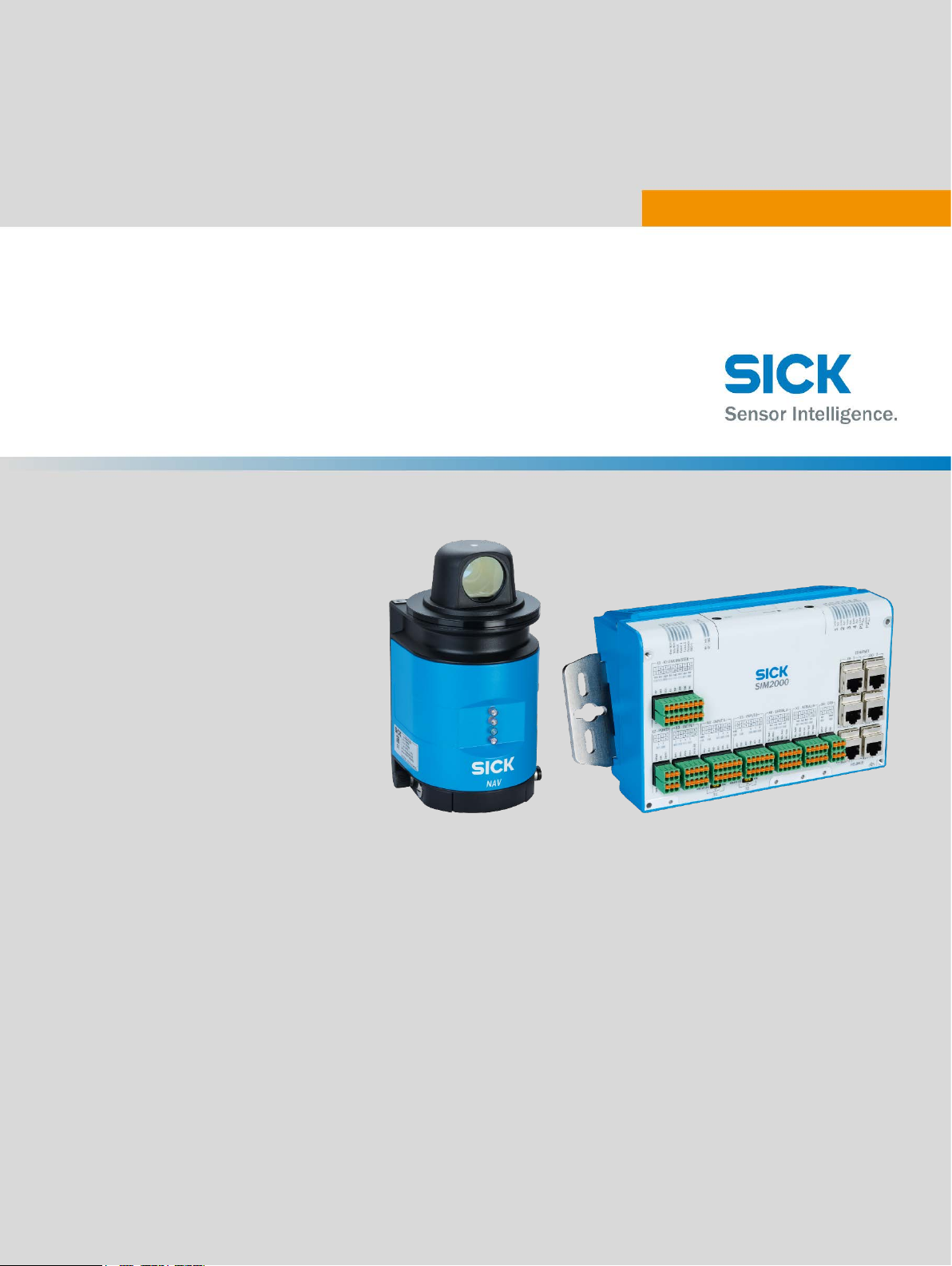
NAV-LOC, SIM2000, NAV310
Laser positioning system
OPERATING INSTRUCTIONS
Page 2

Product described
NAV-LOC with SIM2000 and NAV310
Manufacturer
SICK AG
Erwin-Sick-Str. 1
79183 Waldkirch
Germany
Legal notes
This work is protected by copyright. The associated rights are reserved by SICK AG. Reproduction of this document or parts of this document is only permissible within the
limits of the legal provisions of copyright law. Any modification, abridgment, or translation of this document is prohibited without the express written permission of SICK AG.
The trademarks mentioned in this document are the property of their respective owners.
© SICK AG. All rights reserved.
Original document
This document is an original document of SICK AG.
8023450/2018-12-17| SICK OPERATING INSTRUCTIONS | NAV-LOC
Subject to change without notice
2
Page 3

Contents
Contents
1 Purpose of this document ....................................................................................................... 4
2 Product description .................................................................................................................. 5
2.1 Scope of delivery ................................................................................................................................ 5
2.2 NAV310 2D-LiDAR sensor ................................................................................................................ 6
3 Installation and alignment ...................................................................................................... 7
4 Initial commissioning and demonstration ............................................................................ 8
4.1 Establishment of connections ......................................................................................................... 8
5 Integration and commissioning of the NAV-LOC in a vehicle ............................................ 9
5.1 Connecting the NAV310 voltage supply ......................................................................................... 9
5.2 Connecting the components with connection to the network in the AGV using a switch ... 10
5.3 Synchronization of the NAV310 2D LiDAR sensor with the navigation control .................... 10
6 Setup of the NAV310 ............................................................................................................. 12
8023450/2018-12-17| SICK OPERATING INSTRUCTIONS | NAV-LOC
Subject to change without notice
3
Page 4

1 Purpose of this document
The NAV-LOC consists of one 2D LiDAR sensor and one SIM2000-0A20A00.
Operation of the SIM2000-0A20A00 and its connection and integration in a vehicle are described in
document 8021385 (German) and document 8021386 (English).
The purpose of this document is to explain the special features that must be considered in terms of
voltage supply, interfacing, and synchronization when using a NAV310.
1 Purpose of this document
8023450/2018-12-17| SICK OPERATING INSTRUCTIONS | NAV-LOC
Subject to change without notice
4
Page 5

2 Product description
No. of
Component
1
NAV310-3211 laser position sensor
1
SIM2000-0A20A00 including “navigation control” application
2.1 Scope of delivery
The NAV-LOC with a NAV310 is available in a range of variants depending on the requirements:
2 Product description
The delivery of the NAV-LOC includes the following components:
units
Please note: Cables for the voltage supply and data lines are not included with delivery and can optionally be ordered as accessories.
Sources for obtaining more information
Additional information about the SIM2000-0A20A00 and its optional accessories can be found in the
following places:
• Operating instructions of the SIM2000-0A20A00 online at www.sick.com
and input of the part
number in the search field: 8020763 (German) or 8020764 (English).
• (www.sick.com) for detailed technical data (online data sheet)
8023450/2018-12-17| SICK OPERATING INSTRUCTIONS | NAV-LOC
Subject to change without notice
5
Page 6

2.2 NAV310 2D-LiDAR sensor
Additional information on the NAV310 with notes on mounting, installation, and commissioning can
be found online in the operating instructions (SICK document no.: 8016534 (German) and 8016535
(English)) and in the additional information on the product page of the NAV310 (www.sick.com
You can find technical information for NAV310 telegrams for CoLa A/B under part number 8016855
and for the USP protocol under part number 8016687.
2 Product description
).
8023450/2018-12-17| SICK OPERATING INSTRUCTIONS | NAV-LOC
Subject to change without notice
6
Page 7

3 Installation and alignment
NAV310
SIM2000-0A20A00
AGV computer
The NAV310 should be installed according to the description in the operating instructions (see document at: www.sick.com/NAV310
It should be possible to tilt the scanner in all directions in order to be able to align the scanner horizontally so that the scan plane of the sensor runs parallel to the floor surface.
The sensor must be fixed to a vehicle so that the alignment of the sensor cannot be changed on accident.
The sensor must be mounted in such a way that the contour of the vehicle itself is not within the
measurement area of the LiDAR sensor. When using a NAV3xx scanner, the scanner must be
mounted on the underside!
Ideally, alignment is done in an area with an even floor area intended for service work.
Alignment, at least, should be carried out with a spirit level, which can be placed on the motor crown
(if the scanner does not rotate).
Use the scan visualization in SOPAS ET to verify the generated measured values and the measuring
range online.
1. Select NAV310, MONITOR, SCAN DISPLAY in the project tree.
2. To start the measurement, click the PLAY button.
3. Compare the measurement line with the required result.
Important! The SCAN VIEW on the MONITOR depends on the available processing power of the PC
and is not output in real time. For this reason not all measured values are displayed.
).
3 Installation and alignment
Typical installation of the NAV-LOC on an AGV
8023450/2018-12-17| SICK OPERATING INSTRUCTIONS | NAV-LOC
Subject to change without notice
7
Page 8

4 Initial commissioning and demonstration
4 Initial commissioning and demonstration
4.1 Establishment of connections
The connection of the voltage supply for the SIM2000-0A20A00 is described in chapter 7.3 of the
NAV-LOC operating instructions.
The Ethernet interface of the SIM can be used for direct connection of the scanner and the PC.
The connection variant for vehicle integration using a switch is described in chapter 5.
The connections shown here are based on the default settings of the SIM (192.168.0.1) and the
NAV310 (192.168.1.10). The Ethernet interface of the PC is set to an IP address in the range
192.168.0.2 to 192.168.0.255 in this case.
8023450/2018-12-17| SICK OPERATING INSTRUCTIONS | NAV-LOC
Subject to change without notice
8
Page 9

5 Integration and commissioning of the NAV-LOC in a vehicle
5 Integration and commissioning of the NAV-LOC in a
vehicle
5.1 Connecting the NAV310 voltage supply
Connecting the voltage supply for the NAV310 is described in detail in the operating instructions (BANAV310en_8016534) in chapter 5. Here is a short summary:
Supply voltage:
24 V DC ± 15% acc. to IEC 60364441
(observe permissible lengths of cable in table 11 on page 33 of the BANAV310en_8016534 manual)
The NAV310 consumes the following:
• Maximum 36 W when switching on without wired switching outputs
• Typically 12 W during operation, additional maximum 12 W with wired switching output
The voltage supply/the external power supply unit for voltage supply must be able to continuously
provide at least 40 W, or continuously provide at least 48 W when the switching output is wired.
Connections of the NAV310
Pin assignment of the “Power” connection on the NAV310
For example, a cable with a length of 5 m with part number 6043440 and open ends is available for
supplying the NAV310; it can be shortened if necessary.
8023450/2018-12-17| SICK OPERATING INSTRUCTIONS | NAV-LOC
Subject to change without notice
9
Page 10

5 Integration and commissioning of the NAV-LOC in a vehicle
5.2 Connecting the components with connection to the network in
the AGV using a switch
The vehicle control must have at least one Ethernet interface in order to communicate with the NAVLOC.
When using a switch, all components must be set in the same IP number range or a DHCP server
must be available. In this configuration, access is possible from the PC and vehicle computer to the
SIM and the laser scanner.
Integrating the NAV-LOC into an AGV
5.3 Synchronization of the NAV310 2D LiDAR sensor with the
navigation control
The navigation control synchronizes with the timer of the connected NAV310 scanner for precise assignment of the current scan.
The synchronization described below is essential for trouble-free operation.
The NAV310 outputs a signal depending on the position of the scanner head.
This signal is used to synchronize the scans and balance out different run times via the Ethernet interface.
8023450/2018-12-17| SICK OPERATING INSTRUCTIONS | NAV-LOC
Subject to change without notice
10
Page 11

5 Integration and commissioning of the NAV-LOC in a vehicle
A pulse on pin 4 (digital output 1) of the NAV310 is selected for synchronization.
In order to access this pin, a 5-wire cable, such as with part number 6043440 (5 m length, open
ends) must be used without fail; it can be shortened if necessary.
NOTE
For navigation control to be able to evaluate the hardware signal of the scanner, it is important to
connect switching output OUT 1 from the scanner, which is available on the black wire of the 5-pin
supply cable, to input X4-1 (IN1+) of the SIM.
Wiring example of a voltage supply of the SIM2000-0A20A00 and NAV310
NOTE
Monitor LED 1 sends a common signal when sync signals are received by the connected scanner.
8023450/2018-12-17| SICK OPERATING INSTRUCTIONS | NAV-LOC
Subject to change without notice
11
Page 12

6 Setup of the NAV310
The IP address of the scanner must be tested and, if necessary, set to an appropriate address for
communication between the SIM and the NAV310.
The default setting of the NAV310 is 192.168.1.10 and can be changed by the SOPAS ET configuration program if necessary.
6 Setup of the NAV310
Configuration of the Ethernet interface scanner
8023450/2018-12-17| SICK OPERATING INSTRUCTIONS | NAV-LOC
Subject to change without notice
12
Page 13

8023450/en/2018-12-17
Australia
Phone +61 3 9457 0600
1800 334 802 – toll-free E-mail
sales@sick.com.au
Austria
Phone +43 22 36 62 28 8-0
E-mail office@sick.at
Belgium/Luxembourg
Phone +32 2 466 55 66
E-mail info@sick.be
Brazil
Phone +55 11 3215-4900
E-mail marketing@sick.com.br
Canada
Phone +1 905 771 14 44
E-mail information@sick.com
Czech Republic
Phone +420 2 57 91 18 50
E-mail sick@sick.cz
Chile
Phone +56 2 2274 7430
E-mail info@schadler.com
China
Phone +86 20 2882 3600
E-mail info.china@sick.net.cn
Denmark
Phone +45 45 82 64 00
E-mail sick@sick.dk
Finland
Phone +358-9-2515 800
E-mail sick@sick.fi
France
Phone +33 1 64 62 35 00
E-mail info@sick.fr
Germany
Phone +49 211 5301-301
E-mail info@sick.de
Hong Kong
Phone +852 2153 6300
E-mail ghk@sick.com.hk
Hungary
Phone +36 1 371 2680
E-mail office@sick.hu
India
Phone +91 22 6119 8900
E-mail info@sick-india.com
Israel
Phone +972 4 6881000
E-mail info@sick-sensors.com
Italy
Phone +39 02 274341
E-mail info@sick.it
Japan
Phone +81 3 5309 2112
E-mail support@sick.jp
Malaysia
Phone +6 03 8080 7425
E-mail enquiry.my@sick.com
Mexico
Phone +52 (472) 748 9451
E-mail mario.garcia@sick.com
Netherlands
Phone +31 30 2044 000
E-mail info@sick.nl
New Zealand
Phone +64 9 415 0459
0800 222 278 – toll-free E-mail
sales@sick.co.nz
Norway
Phone +47 67 81 50 00
E-mail sick@sick.no
Poland
Phone +48 22 539 41 00
E-mail info@sick.pl
Romania
Phone +40 356 171 120
E-mail office@sick.ro
Russia
Phone +7 495 775 05 30
E-mail info@sick.ru
Singapore
Phone +65 6744 3732
E-mail sales.gsg@sick.com
Slovakia
Phone +421 482 901201
E-mail mail@sick-sk.sk
Slovenia
Phone +386 591 788 49
E-mail office@sick.si
South Africa
Phone +27 11 472 3733
E-mail info@sickautomation.co.za
South Korea
Phone +82 2 786 6321
E-mail info@sickkorea.net
Spain
Phone +34 93 480 31 00
E-mail info@sick.es
Sweden
Phone +46 10 110 10 00
E-mail info@sick.se
Switzerland
Phone +41 41 619 29 39
E-mail contact@sick.ch
Taiwan
Phone +886 2 2375-6288
E-mail sales@sick.com.tw
Thailand
Phone +66 2645 0009
E-mail Ronnie.Lim@sick.com
Turkey
Phone +90 216 528 50 00
E-mail info@sick.com.tr
United Arab Emirates
Phone +971 4 88 65 878
E-mail info@sick.ae
United Kingdom
Phone +44 1727 831121
E-mail info@sick.co.uk
USA
Phone +1 800 325 7425
E-mail info@sick.com
Vietnam
Phone +84 945452999
E-mail
Ngo.Duy.Linh@sick.com
Further locations at www.sick.com
SICK AG | Waldkirch | Germany | www.sick.com
 Loading...