

Page 1

MAX48
B E T R I E B S A N L E I T U N G
de
en
Page 2

MAX48
B E T R I E B S A N L E I T U N G
de
en
Page 3

Alle Rechte vorbehalten. Irrtümer und Änderungen vorbehalten.
1 Zu Ihrer Sicherheit
1.1 Sicherheitshinweise
Ausführliche Technische Information MAX48 zum Download verfügbar unter
www.sick.com/MAX48
Vor der Inbetriebnahme die Technische Information lesen
•
Anschluss, Montage und Einstellung nur durch Fachpersonal
•
Kein Sicherheitsbauteil gemäß EU-Maschinenrichtlinie
•
1.2 Allgemeine Hinweise
Falls durch Störung oder Ausfall des Geräts Personen gefährdet sind oder Betriebsein‐
richtungen beschädigt werden könnten, so ist dies durch geeignete Schutzvorrichtun‐
gen wie z. B. NOT-AUS-Systeme zu verhindern.
Bei nicht korrekter Funktionsfähigkeit ist das Gerät außer Betrieb zu setzen und gegen
unbefugtes Wiedereinschalten zu sichern.
Um die Funktionsfähigkeit des Geräts zu gewährleisten, sind folgende Punkte zu beach‐
ten:
BETRIEBSANLEITUNG
Das Gerät vor mechanischen Beschädigungen beim Einbau schützen
•
Das Gerät nicht öffnen
•
Die korrekte Polung, Versorgungsspannung und Steuerimpulse anschließen
•
Die zulässigen Betriebs- und Umgebungsbedingen für das Gerät einhalten
•
Die Funktionsfähigkeit des Geräts regelmäßig prüfen und dokumentieren
•
2 Produktbeschreibung
2.1 Zweck des Geräts
Der Sensor MAX48 ist für Positionsmessungen in Anwendungen der Mobilhydraulik
bestimmt und dient so der Steuerung hydraulischer Komponenten von Baumaschinen,
z. B. in Hydraulikzylindern. Das robuste Gehäuse bietet optimalen Schutz gegen Staub,
Witterungseinflüsse, Vibrationen, umgebende Medien sowie elektrische und
magnetische Felder.
Das Gerät ist ein Zubehörteil und muss an eine geeignete elektronische Kontrolleinheit
angeschlossen werden.
2.2
Geräte-Varianten
Das Gerät ist erhältlich in den Varianten:
M12 Stecker (4-polig) oder PUR-Kabel mit 3 Adern
•
3 Montage
3.1 Allgemeine Vorbereitung
Beachten Sie bei der Planung der Montage die jeweiligen Maßzeichnungen. Achten Sie
zudem bei der Ausrichtung des Gerätes und des Anschlusses auf Folgendes:
Leitungen nicht über scharfe Kanten oder heiße Oberflächen legen. Ausreichende
b
Biegeradien und Zugentlastungen verwenden.
8021471/2017-08-01 | SICK B ET R IE B SA N LE I TU N G | MAX48
Irrtümer und Änderungen vorbehalten
3
Page 4
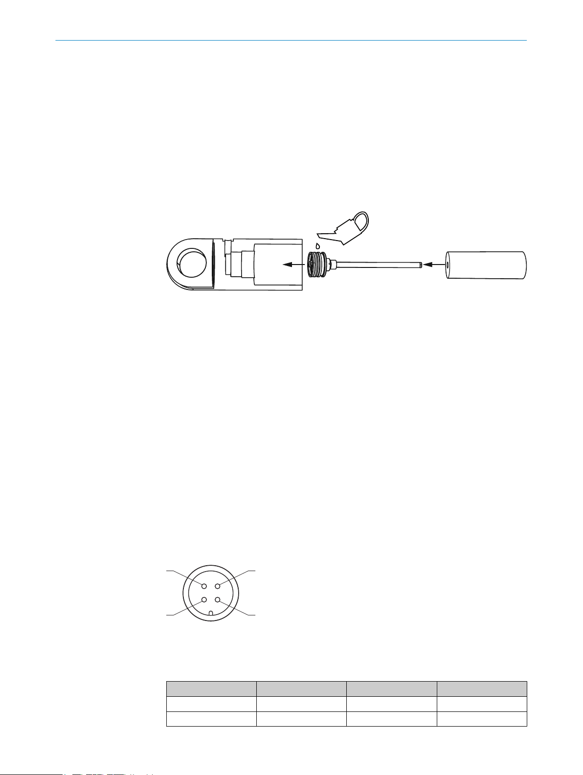
4
3
1
2
BETRIEBSANLEITUNG
3.2 Montagevorbereitung
Einbauraum des Sensors vorbereiten.
b
Einbauraum der Kolbenstange vorbereiten.
b
Einführungs-Fase vorbereiten.
b
Bohrung für Sicherungsschraube vorbereiten.
b
Bohrung für Steckersystem vorbereiten.
b
Kolben für Positionsmagnet vorbereiten.
b
Positionsmagnet einbauen.
b
3.3
Montage in den Zylinder
Abbildung 1: Montageschritte
Sensor mit M12 Steckersystem oder Sensor mit Kabelanschluss und -verschrau‐
b
bung montieren.
Sicherungsschraube anbringen.
b
4 Elektrische Installation
4.1 Elektrischer Anschluss
Das Gerät ist mit einem M12 Steckersystem ausgestattet.
Alternativ steht auch eine Variante mit Kabelanschluss zur Auswahl. Dafür sind elektri‐
sche Gerätestecker zu verwenden.
Schutzarten
Zur Gewährleistung der Schutzart IP69K (M12 Steckersystem) wird ein entsprechender
Gegenstecker benötigt.
4.2 Anschlusspläne, Pinbelegung
M12 Steckersystem
Abbildung 2: Pinbelegung M12
Pinbelegung gemäß Typenschlüssel, Position 13.
Pinbelegung M12
Typenschlüssel A B M
12/24 VDC 1 1 2
4
B ET R IE B SA N LE I TU N G | MAX48 8021471/2017-08-01 | SICK
GND (0 V) 3 3 3
Irrtümer und Änderungen vorbehalten
Page 5
Typenschlüssel A B M
+12/24 VDC
GND
SIG
ECU
BAT
+
–
GEN
M
1
2
+12/24 VDC
Signal 4 2 4
n.c. 2 4 1
Zuordnung Aderfarben (Kabelanschluss: Typenschlüssel, Position 13 = "K")
12/24 VDC BR (braun)
GND (0 V) BL (blau)
Signal Spannung, je nach Variante BK (schwarz)
Signal Strom, je nach Variante WH (weiss)
4.3 Anschlussreihenfolge
Die Anschlussreihenfolge wie folgt durchführen:
1. Spannungsversorgung 12/24 VDC anschließen.
2. GND (0 V) verbinden.
3. Signal anschließen.
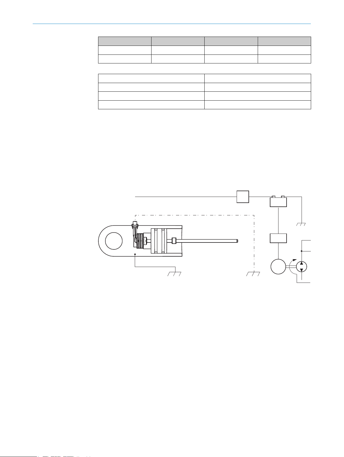
4.4 Anschlussschema an Fahrzeugelektronik
Maschinenmasse
BETRIEBSANLEITUNG
Abbildung 3: Anschlussschema
Kabelschirm (optional)
1
Chassis GND
2
Um die fehlerfreie Funktionsfähigkeit des Geräts sicherzustellen, muss der Zylinder an
der Maschinenmasse anliegen (Chassis GND).
Durch den mechanischen Kontakt mit anderen Maschinenkomponenten ist der
Potenzialausgleich des Zylinders gegeben. Falls der Zylinder isoliert montiert ist, muss
eine separate Erdung, z. B. mit einem Erdungsband, direkt am Zylinder erfolgen.
Kabelschirmung
Das Gerät ist im verbauten Zustand durch den Zylinder ausreichend geschirmt und ver‐
fügt über keine gesonderte Schirmung. Wird eine geschirmte Leitung eingesetzt, so ist
je nach Anwendungssituation zu prüfen, ob die Schirmung beidseitig auf Maschinen‐
masse gelegt wird. In der Umgebung befindliche Hochspannungs- und Hochfrequenzfel‐
der können dabei einen Einfluss auf die Schirmung und die Signale im Kabel haben.
8021471/2017-08-01 | SICK B ET R IE B SA N LE I TU N G | MAX48
Irrtümer und Änderungen vorbehalten
5
Page 6

+ UB
+
GND GND GND
GND
R1
50R
C1
Controller
Input
A/D Wandler
z. B. 12 bit →
4096 Schritte
BETRIEBSANLEITUNG
5 Inbetriebnahme
5.1 Gerät inbetriebnehmen
Elektrische Verbindungen auf richtigen Anschluss überprüfen.
b
Geeignete Sicherung auswählen.
b
Filterbeschaltung einrichten.
b
Gerät in Betrieb nehmen.
b
Sensorfunktion überprüfen.
b
5.2 Geeignete Sicherung auswählen
Für die Auswahl einer geeigneten Sicherung ist der kurzzeitige Spitzenstrom beim erst‐
maligen Einschalten zu berücksichtigen:
Einschaltstrom beim Einschalten
Einschaltstrom bei Betriebsspannung 12 VDC typ. 2,5 A / 50 μsec
Einschaltstrom bei Betriebsspannung 24 VDC typ. 5,0 A / 50 μsec
5.3 Filterbeschaltung einrichten
Thermisches Rauschen, z. B. von Widerständen, wird bei entsprechender Verstärkung
am Signalausgang sichtbar. Die Restwelligkeit der Versorgungsspannung und andere
Störeinflüsse, z. B. elektro-magnetische Störeinstrahlungen, beinflussen ebenfalls die
Qualität des analogen Ausgangssignals. Zur Rauschunterdrückung bei analoger Mess‐
werterfassung ist ein Filter obligatorisch.
Geeignet ist beispielsweise eine Kombination aus R1 = 50 Ω und C1 = 100nF bis 1µF .
Dabei liegt die Verzögerung des Signals innerhalb der Zykluszeit (interne Messrate)
und verändert das dynamische Verhalten nur unwesentlich.
Abbildung 4: Filterbeschaltung
WICHTIG
Der A/D-Wandler am Eingang der verwendeten elektrischen Steuerung wirkt sich auf
die Auflösung am Sensor aus, z. B.:
8 bit = 256 Schritte
•
10 bit = 1024 Schritte
•
12 bit = 4096 Schritte
•
6
B ET R IE B SA N LE I TU N G | MAX48 8021471/2017-08-01 | SICK
Signalausgang während des Einschaltens
Während der Einschaltzeit ist der Signalausgang am Gerät ≥ F.S.O = Full Scale Output.
Danach ist das Gerät betriebsbereit.
Irrtümer und Änderungen vorbehalten
Page 7

Signalausgang während des Einschaltens
F.S.O Während des Einschaltvor‐
20 mA > 10 mA > 21,0 mA
4,75 Volt > 5 VDC > 5,1 VDC
4,50 Volt > 5 VDC > 5,1 VDC
9,50 Volt > 5 VDC > 10,0 VDC
Fehlerfall:
a) fehlender Positionsmagnet
b) Fehlfunktion oder Ausfall des magnetostriktiven Elements
5.4 Toleranzbetrachtung des Setzpunkts
Die Setzpunkte (Null-/Endpunkt) des Geräts werden vom Hersteller mit einer Toleranz
von ± 1 mm abgeglichen.
WICHTIG
Weitere Toleranzen sind beim Einbau des Zylinders zu beachten.
BETRIEBSANLEITUNG
Ausgangssignal
Im Fehlerfall
gangs
Beim Einlernvorgang (Teach-In) fährt die Kolbenstange den Null- bzw. Endpunkt an, um
alle Toleranzen der Zylinder-Sensor Kombination zu eliminieren. Die gemessenen Sig‐
nale werden in der Steuerung dementsprechend programmiert. Bei Betrieb ohne TeachIn sind folgende Angaben zu Toleranzen zu beachten:
Toleranzen bei Betrieb ohne Teach-In
Beispiel am Messbereich 400 mm
Spanne 4000 mV 16 mA
Signal 0,5 ... 4,5 V 4 ... 20 mA
Null-/Endpunkt ± 1,0 mm ± 10 mV ± 0,04 mA
Positionsmagnet ± 1,0 mm ± 10 mV ± 0,04 mA
mech. Zusammenbau ± 0,5 mm ± 5 mV ± 0,02 mA
Summe aller Toleranzen ± 2,5 mm ± 25 mV ± 0,10 mA
Betrachtung für Null-Endpunkt
Null-Endpunkt
Beispiel am Messbereich 400 mm
Ausgang VDC-Ausgang mA-Ausgang
Signal 0,5 ... 4,50 V 4 ... 20 mA
Nullpunkt ± 25 mV ± 0,10 mA
min. Nullpunkt 0,475 mVDC 3,90 mA
max. Nullpunkt 0,525 mVDC 4,10 mA
Endpunkt (F.S.) ± 25 mVDC ± 0,10 mA
min. Endpunkt 4,475 mVDC 19,90 mA
max. Endpunkt 4,525 mVDC 20,10 mA
Nach dem Einbau des Sensors in den Zylinder kommt es durch die zulässigen Toleran‐
zen zu Abweichungen von den Soll-Werten. Die Abweichungen sind bei der Festlegung
von Grenzwerten in der auslesenden Steuerung zu berücksichtigen:
8021471/2017-08-01 | SICK B ET R IE B SA N LE I TU N G | MAX48
Irrtümer und Änderungen vorbehalten
7
Page 8

BETRIEBSANLEITUNG
Abweichung von Grenzwerten
Typische Werte
VDC mA
Zylinderhub (mm) 200 400 800 200 400 800
Toleranzen ± 50 mV ± 25 mV ± 15 mV ± 0,20 mA ± 0,10 mA ± 0,05 mA
6 Instandhaltung
6.1 Überprüfen der Gerätefunktion
Um die Funktionsfähigkeit des Geräts zu gewährleisten, sind folgende Punkte zu beach‐
ten:
Das Gerät vor mechanischen Beschädigungen beim Einbau schützen
•
Das Gerät nicht öffnen
•
Die korrekte Polung, Versorgungsspannung und Steuerimpulse anschließen
•
Die zulässigen Betriebs- und Umgebungsbedingen für das Gerät beachten
•
Die Funktionsfähigkeit des Geräts regelmäßig prüfen und dokumentieren
•
Weitere Maßnahmen, wie z. B. das Messen des Ausgangssignals per Multimeter, sind in
der Technischen Information beschrieben.
6.2 Reparatur
Notwendige Reparaturen am Gerät dürfen nur vom SICK-Service durchgeführt werden.
7 Außerbetriebnahme
7.1 Demontage
Bei der Demontage der Zylinder sowie der Sensoren ist darauf zu achten, dass keine
Stecker, Kabel und Kabelenden beschädigt werden können.
7.2 Entsorgung
Ein unbrauchbar gewordenes Gerät ist umweltgerecht gemäß der jeweils gültigen län‐
derspezifischen Abfallbeseitigungsvorschriften zu entsorgen. Als Elektronikschrott darf
das Gerät keinesfalls dem Hausmüll beigegeben werden.
8
B ET R IE B SA N LE I TU N G | MAX48 8021471/2017-08-01 | SICK
Irrtümer und Änderungen vorbehalten
Page 9

MAX48
O P E R A T I N G I N S T R U C T I O N S
de
en
Page 10

OPERATING INSTRUCTIONS
All rights reserved. Subject to change without notice.
1 Safety information
1.1 Safety notes
Detailed technical information for the MAX48 is available for downloading from
www.sick.com/MAX48
Please read the technical information before commissioning
•
Connection, installation, and programming is only to be performed by trained spe‐
•
cialists
Not a safety component according to the EU Machinery Directive
•
1.2 General notes
Should persons be placed at risk, or operating equipment potentially be damaged in
the event of a malfunction or failure of the device, this must be prevented by means of
suitable protective devices, e. g., emergency shutdown systems.
If the device is not functioning correctly, it must be taken out of operation and secured
against unauthorized operation.
To guarantee proper operation of the device, please observe the following:
Protect the device against mechanical stress during installation
•
Do not open the device
•
Connect the device with the correct polarity, supply voltage and control pulses
•
Observe the permissible operating and ambient conditions for the device
•
Regularly check the device for correct operation and document the results
•
2 Product description
2.1 Purpose of the device
The MAX48 sensor is designed to take position measurements in mobile hydraulic
applications and therefore can be used to control the hydraulic components of con‐
struction machinery, e.g., in hydraulic cylinders. The rugged housing offers optimal pro‐
tection against dust, climatic influences, vibrations, surrounding media as well as
electrical and magnetic fields.
The device is an accessory and must be connected to a suitable electronic control unit.
2.2 Device variants
The device is available in the following variants:
M12 male connector (4-pin) or 3-wire PUR cable
•
3 Mounting
3.1 General preparation
Observe the dimensional drawings when preparing to install the system. Also pay atten‐
tion to the following when aligning and connecting the device:
Do not lay any cables across sharp edges or hot surfaces. Use adequate bend
b
radii and strain-relief clamps.
10
O PE R AT I NG IN S TR U CT I ON S | MAX48 8021471/2017-08-01 | SICK
Subject to change without notice
Page 11

3.2 Pre-installation steps
4
3
1
2
Prepare the installation cavity for the sensor.
b
Prepare the installation cavity for the piston rod.
b
Prepare the insertion chamfer.
b
Prepare the bore hole for the retaining screw.
b
Prepare the bore hole for the connector system.
b
Prepare the piston for the position magnet.
b
Install the position magnet.
b
OPERATING INSTRUCTIONS
3.3
Installation in the cylinder
Figure 1: Installation steps
Install the sensor using the M12 connector system, or the cable connector and
b
screwed cable gland.
Install the retaining screw.
b
4 Electrical installation
4.1 Electrical connection
The device is equipped with an M12 connector system.
A variant with a cable connection is also available. Male device connectors must be
used in this case.
Enclosure ratings
To guarantee an IP69K enclosure rating (M12 connector system), a suitable mating
connector must be used.
4.2 Connection diagrams, pin assignment
M12 connector system
Figure 2: M12 pin assignment
Pin assignment as per position 13 of the type code.
M12 pin assignment
Type code A B M
12/24 VDC 1 1 2
8021471/2017-08-01 | SICK O PE R AT I NG IN S TR U CT I ON S | MA X48
Subject to change without notice
GND (0 V) 3 3 3
11
Page 12

+12/24 VDC
GND
SIG
ECU
BAT
+
–
GEN
M
1
2
+12/24 VDC
OPERATING INSTRUCTIONS
Type code A B M
Signal 4 2 4
n.c. 2 4 1
Allocation of wire colors (cable connector: position 13 of type code = “K”)
12/24 VDC BR (brown)
GND (0 V) BL (blue)
Signal voltage, depending on variant BK (black)
Signal current, depending on variant WH (white)
4.3 Connection sequence
Connect the wires in the following sequence:
1. Connect the 12/24 VDC voltage supply.
2. Connect the GND (0 V).
3. Connect the signal.
4.4 Connection diagram for vehicle electronics
Machine ground
12
Figure 3: Connection diagram
Cable shielding (optional)
1
Chassis GND
2
To guarantee fault-free operation of the device, the cylinder must be connected to
machine ground (Chassis GND).
The physical contact with another machine component equalizes the potential of the
cylinder. If the cylinder is mounted in an insulated manner, a separate grounding must
be provided, e.g., by connecting a ground strap directly to the cylinder.
Cable shielding
The device is adequately shielded by the cylinder when installed, and therefore has not
been provided with its own shielding. If a shielded cable is used, it is necessary to
check, depending on the application, whether one side or both sides of the shield
should be connected to machine ground. Any high voltage or high frequency fields in
the vicinity can influence the shielding and the signal in the cable.
O PE R AT I NG IN S TR U CT I ON S | MAX48 8021471/2017-08-01 | SICK
Subject to change without notice
Page 13

5 Commissioning
SIG
+
GND GND GND
GND
R1
50R
C1
Controller
Input
A/D converter
e.g., 12 bit →
4,096steps
SIG
5.1 Commissioning the device
Check that the connectors have been connected correctly.
b
Select a suitable fuse.
b
Set up the filter wiring.
b
Put the device into operation.
b
Check the sensor function.
b
5.2 Select a suitable fuse
When selecting a suitable fuse, the transient peak current when switching on the
device for the time must be taken into consideration:
Inrush current when switching the device on
Inrush current for an supply voltage of 12 VDC 2.5 A / 50 μsec typical
Inrush current for an supply voltage of 24 VDC 5.0 A / 50 μsec typical
5.3 Set up the filter wiring
OPERATING INSTRUCTIONS
Thermal noise, for example from resistors, becomes evident when the signal output is
amplified sufficiently. The supply voltage ripple and other sources of interference, e.g.,
electromagnetic interference, can also affect the quality of the analog output signal. To
reduce the noise when acquiring analog measurement data, it is essential to use a fil‐
ter.
A suitable filter, for example, is a combination of R1 = 50 Ω and C1 = 100nF bis 1µF.
This will keep the signal delay time within the cycle time (internal measurement fre‐
quency) while not changing the dynamic behavior significantly.
Figure 4: Filter wiring
NOTICE
The A/D converter at the input of the installed electrical controller will determine the
resolution of the sensor, e.g.,:
8 bit = 256 steps
•
10 bit = 1,024 steps
•
12 bit = 4,096 steps
•
Signal output when switching on the device
When switching on the device, the signal output is ≥ F.S.O = Full Scale Output. After that
8021471/2017-08-01 | SICK O PE R AT I NG IN S TR U CT I ON S | MA X48
Subject to change without notice
the device is ready for use.
13
Page 14

OPERATING INSTRUCTIONS
Signal output when switching on the device
F.S.O During powering on In case of internal failure
20 mA > 10 mA > 21.0 mA
4.75 Volt > 5 VDC > 5.1 VDC
4.50 Volt > 5 VDC > 5.1 VDC
9.50 Volt > 5 VDC > 10.0 VDC
Internal failure:
a) missing position magnet
b) malfunction of magnetostrictive device
5.4 Tolerance considerations for the set point
The set points (zero/end point) of the device are adjusted by the manufacturer to a tol‐
erance of ± 1 mm.
NOTICE
Further tolerances must be observed when installing the cylinder.
Output signal
During teach-in, the piston rod moves to the zero point and to the end point in order to
eliminate all tolerances in the cylinder/sensor combination. The measured signals are
programmed in the controller accordingly. When operating the device without teach-in,
please note the following tolerance-related information:
Tolerances when operating the device without teach-in
Example for a measuring range of 400 mm
Range 4,000 mV 16 mA
Signal 0.5 ... 4.5 V 4 ... 20 mA
Zero/end point ± 1.0 mm ± 10 mV ± 0.04 mA
Position magnet ± 1.0 mm ± 10 mV ± 0.04 mA
Mechanical assembly ± 0.5 mm ± 5 mV ± 0.02 mA
Total of all tolerances ± 2.5 mm ± 25 mV ± 0.10 mA
Considerations for zero end point
Zero end point
Example for a measuring range of 400 mm
Output VDC output mA output
Signal 0.5 ... 4.50 V 4 ... 20 mA
Zero point ± 25 mV ± 0.10 mA
min. zero point 0.475 mVDC 3.90 mA
max. zero point 0.525 mVDC 4.10 mA
End point (F.S.) ± 25 mVDC ± 0.10 mA
min. end point 4.475 mVDC 19.90 mA
max. end point 4.525 mVDC 20.10 mA
14
After installation of the sensor in the cylinder, deviations from the target values will
arise due to these permissible tolerances. These deviations must be taken into consid‐
eration when setting limit values in the controller:
O PE R AT I NG IN S TR U CT I ON S | MAX48 8021471/2017-08-01 | SICK
Subject to change without notice
Page 15

Deviation from the limit values
Typical values
Cylinder stroke
(mm)
Tolerances ± 50 mV ± 25 mV ± 15 mV ± 0.20 mA ± 0.10 mA ± 0.05 mA
6 Maintenance
6.1 Checking the device function
To guarantee proper operation of the device, please observe the following:
Protect the device against mechanical stress during installation
•
Do not open the device
•
Connect the device with the correct polarity, supply voltage and control pulses
•
Observe the permissible operating and ambient conditions for the device
•
Regularly check the device for correct operation and document the results
•
Further measures, for example measuring the output signal using a multimeter, are
described in the Technical Information.
OPERATING INSTRUCTIONS
VDC mA
200 400 800 200 400 800
6.2 Repairs
All necessary repair work on the device must be carried out by SICK Service.
7 Decommissioning
7.1 Dismantling
When dismantling the cylinder and the sensor, ensure that no male connectors, cables
or cable ends can be damaged in the process.
7.2 Disposal
Any device which can no longer be used must be disposed of in an environmentally
friendly manner in accordance with the applicable country-specific waste disposal regu‐
lations. As the device is categorized as electronic waste, it must never be disposed of
with household waste.
8021471/2017-08-01 | SICK O PE R AT I NG IN S TR U CT I ON S | MA X48
Subject to change without notice
15
Page 16

Further locations at www.sick.com
Australia
Phone +61 3 9457 0600
1800 334 802 – tollfree
E-Mail [email protected]
Austria
Phone +43 22 36 62 28 8-0
E-Mail [email protected]
Belgium/Luxembourg
Phone +32 2 466 55 66
E-Mail [email protected]
Brazil
Phone +55 11 3215-4900
E-Mail [email protected]
Canada
Phone +1 905 771 14 44
E-Mail [email protected]
Czech Republic
Phone +420 2 57 91 18 50
E-Mail [email protected]
Chile
Phone +56 2 2274 7430
E-Mail [email protected]
China
Phone +86 20 2882 3600
E-Mail [email protected]
Denmark
Phone +45 45 82 64 00
E-Mail [email protected]
Finland
Phone +358-9-2515 800
E-Mail [email protected]
France
Phone +33 1 64 62 35 00
E-Mail [email protected]
Germany
Phone +49 211 5301-301
E-Mail [email protected]
Hong Kong
Phone +852 2153 6300
E-Mail [email protected]
Hungary
Phone +36 1 371 2680
E-Mail [email protected]
India
Phone +91 22 6119 8900
E-Mail [email protected]
Israel
Phone +972 4 6881000
E-Mail [email protected]
Italy
Phone +39 02 274341
E-Mail [email protected]
Japan
Phone +81 3 5309 2112
E-Mail [email protected]
Malaysia
Phone +6 03 8080 7425
E-Mail [email protected]
Mexico
Phone +52 (472) 748 9451
E-Mail [email protected]
Netherlands
Phone +31 30 2044 000
E-Mail [email protected]
New Zealand
Phone +64 9 415 0459
0800 222 278 – tollfree
E-Mail [email protected]
Norway
Phone +47 67 81 50 00
E-Mail [email protected]
Poland
Phone +48 22 539 41 00
E-Mail [email protected]
Romania
Phone +40 356 171 120
E-Mail [email protected]
Russia
Phone +7 495 775 05 30
E-Mail [email protected]
Singapore
Phone +65 6744 3732
E-Mail [email protected]
Slovakia
Phone +421 482 901201
E-Mail [email protected]
Slovenia
Phone +386 591 788 49
E-Mail [email protected]
South Africa
Phone +27 11 472 3733
E-Mail [email protected]
South Korea
Phone +82 2 786 6321
E-Mail [email protected]
Spain
Phone +34 93 480 31 00
E-Mail [email protected]
Sweden
Phone +46 10 110 10 00
E-Mail [email protected]
Switzerland
Phone +41 41 619 29 39
E-Mail [email protected]
Taiwan
Phone +886 2 2375-6288
E-Mail [email protected]
Thailand
Phone +66 2645 0009
E-Mail [email protected]
Turkey
Phone +90 216 528 50 00
E-Mail [email protected]
United Arab Emirates
Phone +971 4 88 65 878
E-Mail [email protected]
United Kingdom
Phone +44 1727 831121
E-Mail [email protected]
USA
Phone +1 800 325 7425
E-Mail [email protected]
Vietnam
Phone +84 945452999
E-Mail [email protected]
8021471/2017-08-01/de, en
SICK AG | Waldkirch | Germany | www.sick.com
 Loading...