

Page 1
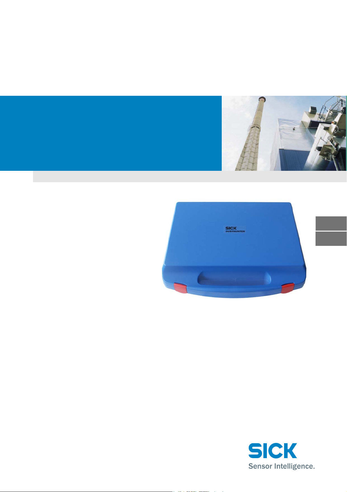
Test Equipment
for DUSTHUNTER C200
Technische Information
Technical Instructions
TECHNICAL INSTRUCTIONS
D
E
Page 2

Dokument-Information
Document Information
Beschriebenes Produkt
Produktname: Test Equipment for DUSTHUNTER C200
Dokument-Identifikation
Titel: Technical Instructions Test Equipment for DUST-
HUNTER C200
Bestellnummer: 8013686
Version: 0.1
Stand: 2012-12
Hersteller
SICK AG
Erwin-Sick-Str. 1 · 79183 Waldkirch · Deutschland
Telefon: +49 7641 469-0
Fax: +49 7641 469-1149
E-Mail: [email protected]
Fertigungsstandort
SICK Engineering GmbH
Bergener Ring 27 · 01458 Ottendorf-Okrilla · Deutschland
Warenzeichen
Windows ist Warenzeichen der Microsoft Corporation.
Andere Produktbezeichnungen in diesem Dokument sind
möglicherweise ebenfalls Warenzeichen und werden hier nur
zum Zweck der Identifikation verwendet.
Original-Dokumente
Die deutsche Ausgabe 8013686 dieses Dokuments ist ein Original-Dokument der SICK AG.
Für die Richtigkeit einer nicht autorisierten Übersetzung übernimmt die SICK AG keine Gewährleistung.
Kontaktieren Sie im Zweifelsfall die SICK AG oder Ihren lokalen Vertreter.
Rechtliche Hinweise
Irrtümer und Änderungen vorbehalten.
© SICK AG. Alle Rechte vorbehalten.
Product
Product name: Test Equipment for DUSTHUNTER C200
Document ID
Title: Technical Instructions Test Equipment for DUST-
HUNTER C200
Order No.: 8013686
Version: 0.1
Release: 2012-12
Manufacturer
SICK AG
Erwin-Sick-Str. 1 · 79183 Waldkirch · Germany
Phone: +49 7641 469-0
Fax: +49 7641 469-1149
E-mail: [email protected]
Place of Manufacture
SICK Engineering GmbH
Bergener Ring 27 · 01458 Ottendorf-Okrilla · Germany
Trademarks
Windows is a trademark of the Microsoft Corporation.
Other product names used in this document may also be trademarks and are only used for identification purposes.
Original Documents
The English edition 8013686 of this document is an original document of SICK AG.
SICK AG assumes no liability for the correctness of an unauthorized translation.
Please contact the manufacturer or your local representative in
case of doubt.
Legal information
Subject to change without notice.
© SICK AG. All rights reserved.
2 Test Equipment for DUSTHUNTER C200 · Technical Instructions · 8013686 V0.1 · © SICK AG
Page 3
Warning Symbols
Hazard (general)
Danger through mains voltage
Hazard by laser radiation
Warning Levels / Signal Words
DANGER
Risk or hazardous situation which will result in severe personal
injury or death.
WARNING
Risk or hazardous situation which could result in severe personal
injury or death.
CAUTION
Hazard or unsafe practice which could result in personal injury or
property damage.
NOTICE
Hazard which could result in property damage.
Information Symbols
Important technical information for this product
Supplementary information
Link to information at another place
Test Equipment for DUSTHUNTER C200 · Technical Instructions · 8013686 V0.1 · © SICK AG 3
Page 4

Inhaltsverzeichnis
1 Allgemeine Hinweise . . . . . . . . . . . . . . . . . . . . . . . . . . . . . . . . . . . . . . . . . . . . . . . . . 6
1.1 Die wichtigsten Gefahren . . . . . . . . . . . . . . . . . . . . . . . . . . . . . . . . . . . . . . . . . . . . . . . . . . . . . 6
1.2 Vorbereitungsarbeiten . . . . . . . . . . . . . . . . . . . . . . . . . . . . . . . . . . . . . . . . . . . . . . . . . . . . . . . . 7
1.2.1 Messsystem in Zustand „Wartung” setzen . . . . . . . . . . . . . . . . . . . . . . . . . . . . . . . . . . . 7
1.2.2 Optische Flächen reinigen . . . . . . . . . . . . . . . . . . . . . . . . . . . . . . . . . . . . . . . . . . . . . . . . . . 8
1.2.3 Verschmutzung kontrollieren . . . . . . . . . . . . . . . . . . . . . . . . . . . . . . . . . . . . . . . . . . . . . . 11
2 Linearitätskontrolle. . . . . . . . . . . . . . . . . . . . . . . . . . . . . . . . . . . . . . . . . . . . . . . . . . 13
2.1 Grundlagen, allgemeine Hinweise. . . . . . . . . . . . . . . . . . . . . . . . . . . . . . . . . . . . . . . . . . . . . 13
2.1.1 Messprinzip . . . . . . . . . . . . . . . . . . . . . . . . . . . . . . . . . . . . . . . . . . . . . . . . . . . . . . . . . . . . . . 13
2.1.2 Komponenten . . . . . . . . . . . . . . . . . . . . . . . . . . . . . . . . . . . . . . . . . . . . . . . . . . . . . . . . . . . . 14
2.1.3 Wichtige Hinweise zur Handhabung . . . . . . . . . . . . . . . . . . . . . . . . . . . . . . . . . . . . . . . . 15
2.2 Linearität überprüfen . . . . . . . . . . . . . . . . . . . . . . . . . . . . . . . . . . . . . . . . . . . . . . . . . . . . . . . . 16
2.2.1 Transmissionsmessung . . . . . . . . . . . . . . . . . . . . . . . . . . . . . . . . . . . . . . . . . . . . . . . . . . . 16
2.2.2 Streulichtmessung. . . . . . . . . . . . . . . . . . . . . . . . . . . . . . . . . . . . . . . . . . . . . . . . . . . . . . . . 18
2.3 Linearitätstest beenden . . . . . . . . . . . . . . . . . . . . . . . . . . . . . . . . . . . . . . . . . . . . . . . . . . . . . 20
D
4 Test Equipment for DUSTHUNTER C200 · Technical Instructions · 8013686 V0.1 · © SICK AG
Irrtümer und Änderungen vorbehalten
Page 5

Test Equipment for DUSTHUNTER C200
Linearitätsmessung
Allgemeine Hinweise
Linearitätskontrolle
D
Irrtümer und Änderungen vorbehalten
Test Equipment for DUSTHUNTER C200 · Technical Instructions · 8013686 V0.1 · © SICK AG 5
Page 6
1 Allgemeine Hinweise
Zu diesem Dokument
Diese Instruktion beschreibt die Benutzung der Prüfmittels zur Linearitätsprüfung der
Sende-/Empfangseinheiten des Staubkonzentrations-Messsystems DUSTHUNTER C200.
Sie gilt nur in Verbindung mit der zugehörigen Betriebsanleitung (BA).
WICHTIG:
Vor Beginn von Arbeiten stets diese Anleitung lesen! Alle Sicherheits- und
Warnhinweise unbedingt beachten!
1.1 Die wichtigsten Gefahren
Gefahren durch heiße und/oder aggressive Gase und/oder hohen Druck
Die Sende-/Empfangseinheit ist direkt am gasführenden Kanal angebaut. Bei allen
Arbeiten am Messsystem sind die gültigen Vorschriften und Sicherheitsbestimmungen der
Anlage zu beachten und notwendige und geeignete Schutzmaßnahmen zu ergreifen.
WARNUNG: Gefahr durch Abgas
Bei Anlagen mit gesundheitsschädigenden Gasen, hohem Druck, hohen
Temperaturen besondere Schutzmaßnahmen beim Öffnen des Gerätes
ergreifen.
D
Gefahr durch Laserlicht
WARNUNG:Gefahr durch Laserlicht
Nie direkt in den Strahlengang blicken
Laserstrahl nicht auf Personen richten
Auf Reflexionen des Laserstrahls achten.
6 Test Equipment for DUSTHUNTER C200 · Technical Instructions · 8013686 V0.1 · © SICK AG
Irrtümer und Änderungen vorbehalten
Page 7
1.2 Vorbereitungsarbeiten
1.2.1 Messsystem in Zustand „Wartung” setzen
Vor der Ausführung der nachfolgend beschriebenen Arbeiten ist das Messsystem mit den
folgenden Schritten in den Zustand „Wartung“ zu setzen.
Messsystem via Laptop/PC mit dem Programm SOPAS ET verbinden und im Register
„Netzwerkscanassistent“ die Schaltfläche „Netzwerk scannen” betätigen.
Im Register „Netzwerkscanassistent / Gefundene Geräte“ die Gerätedatei „MCU“ auswählen und in das Fenster „Projektbaum“ bewegen (siehe BA DUSTHUNTER C200
Abschn. 4.1.4).
Passwort Ebene 1 eingeben (siehe BA DUSTHUNTER C200 Abschn. 4.1.4).
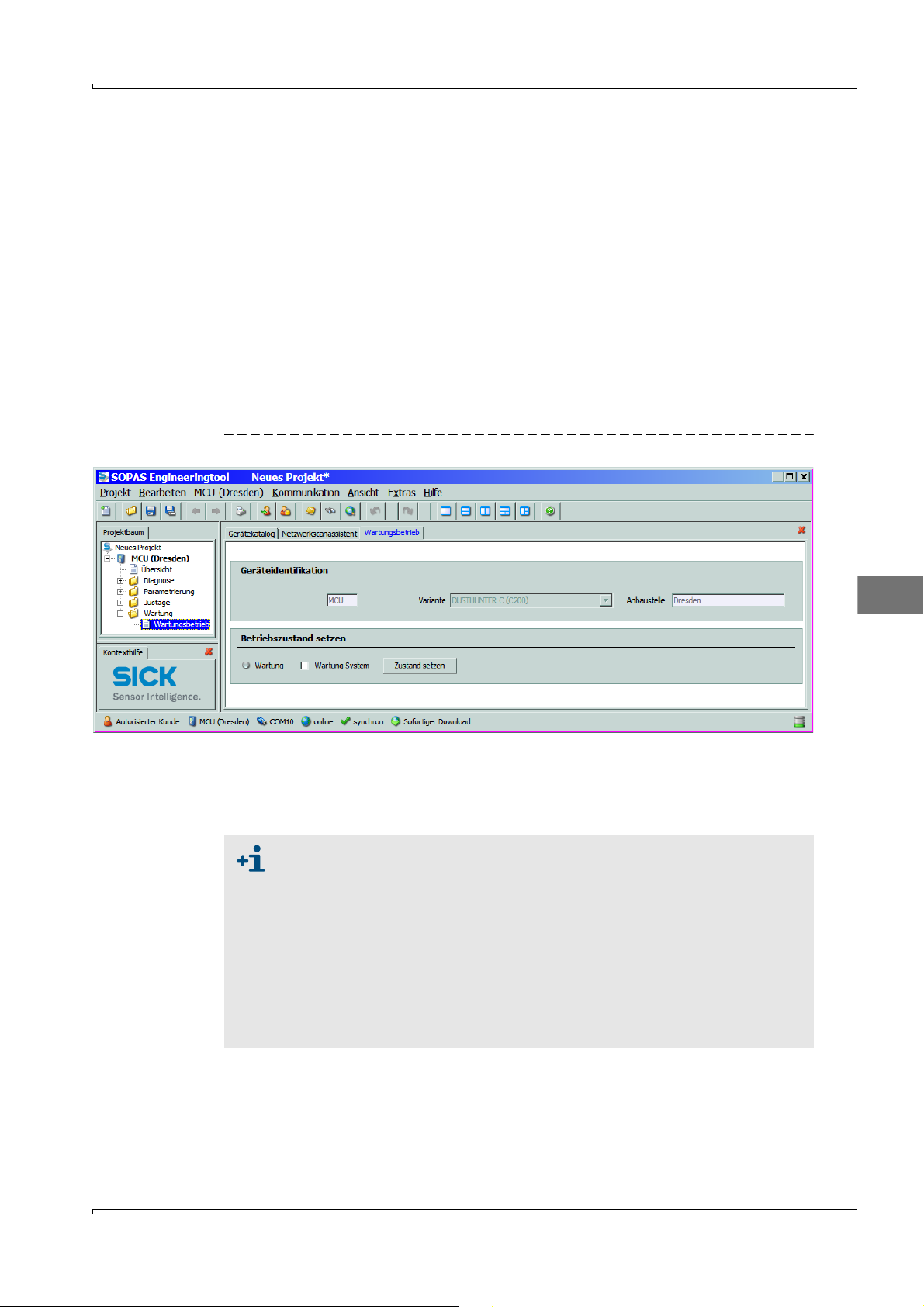
In das Unterverzeichnis „Wartung/Wartungsbetrieb“ wechseln, das Kontrollkästchen
„Wartung System” im Feld „Betriebszustand setzen“ aktivieren und die Schaltfläche
„Zustand setzen“ betätigen (
Bild 1 Zustand „Wartung“ setzen
Bild1).
Im Register „Netzwerkscanassistent / Gefundene Geräte“ die Gerätedatei „DH C200”
auswählen und in das Fenster „Projektbaum“ bewegen.
Passwort Ebene 1 eingeben und Sende-/Empfangseinheit in Zustand „Wartung”
setzen.
Der Zustand „Wartung kann auch über die Tasten am LC-Display (siehe BA
DUSTHUNTER C200 Abschn. 4.6.2) oder durch Anschluss eines externen
Wartungsschalters an die Klemmen für Dig In2 (17, 18) in der MCU ( (siehe
BA DUSTHUNTER C200 Abschn. 3.3.4) gesetzt werden.
Während „Wartung“ wird kein Kontrollzyklus ausgeführt.
Am Analogausgang wird der für „Wartung“ eingestellte Wert ausgegeben
(siehe BA DUSTHUNTER C200 Abschn. 4.3.4). Das gilt auch bei
Vorhandensein einer Störung (Signalisierung am Relaisausgang).
Bei Spannungsausfall wird der Zustand „Wartung“ zurückgesetzt. Das
Messsystem geht in diesem Fall nach Zuschalten der Betriebsspannung
automatisch in „Messung“.
D
Irrtümer und Änderungen vorbehalten
Test Equipment for DUSTHUNTER C200 · Technical Instructions · 8013686 V0.1 · © SICK AG 7
Page 8
1.2.2 Optische Flächen reinigen
Sende-/Empfangseinheit
Griffschrauben lösen und Elektronikeinheit zur Seite schwenken.
Montageflansch und Spülluftstutzen auf Verschmutzung kontrollieren und, falls notwendig, reinigen.
Montageflansch mit Deckel (siehe BA DUSTHUNTER C200 Abschn. 8.4) verschließen.
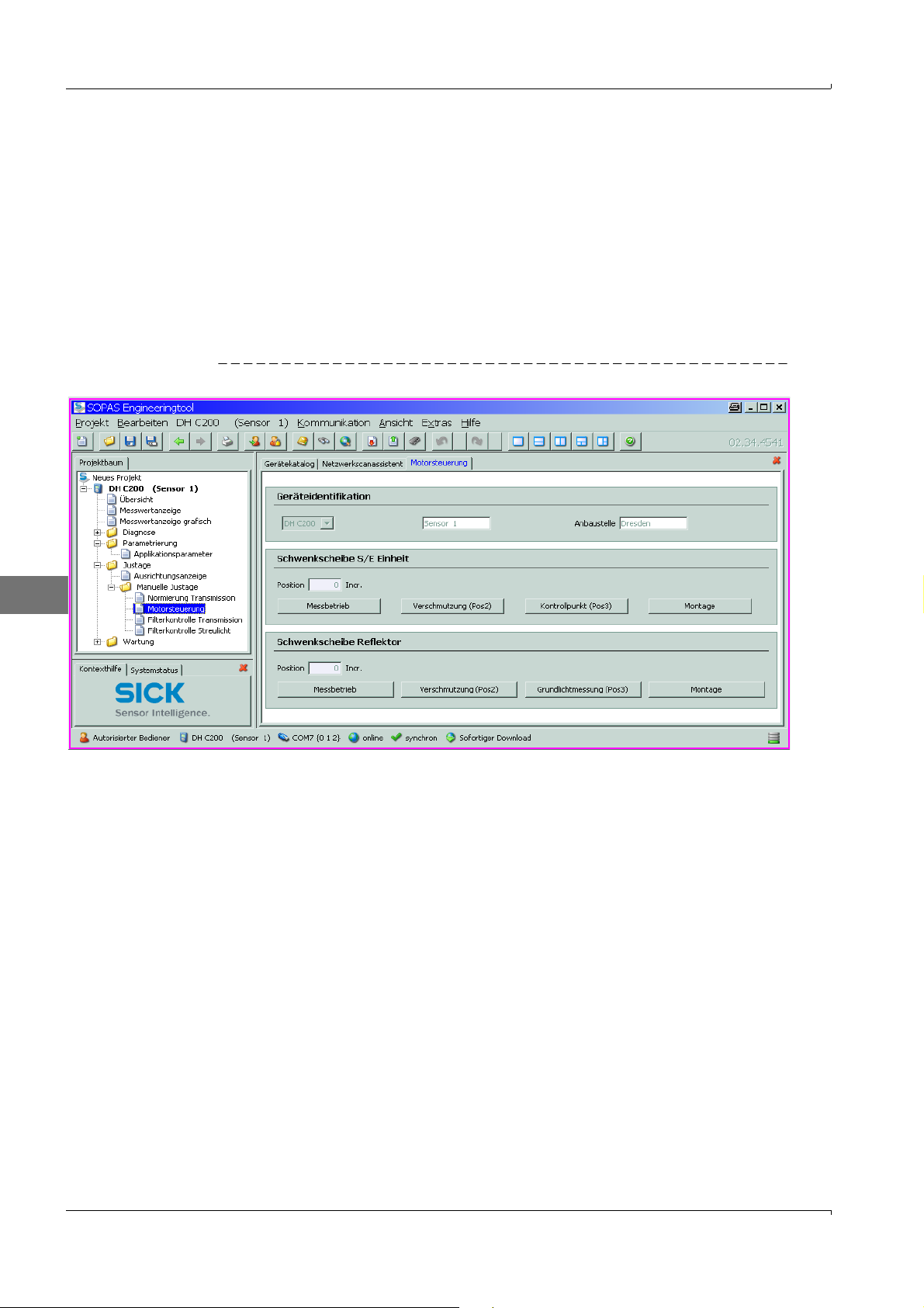
In der Gerätedatei „DH C200” das Verzeichnis „Justage / Manuelle Justage / Motorsteuerung“ öffnen und bei „Schwenkscheibe S/E Einheit” die Schaltfläche „Montage”
betätigen.
Die Schwenkscheibe wird damit in die Reinigungsposition bewegt.
Bild 2 Verzeichnis „Justage / Manuelle Justage / Motorsteuerung“
D
Schwenkscheibenabdeckung (1) abnehmen, Spannfeder (2) zusammendrücken und
Schwenkscheibe (3) von der Achse (4) abziehen.
Glasscheibe (5) (beidseitig), Nullpunktreflektor (6) und Sendeoptik (7) vorsichtig mit
einem Optiktuch reinigen.
8 Test Equipment for DUSTHUNTER C200 · Technical Instructions · 8013686 V0.1 · © SICK AG
Irrtümer und Änderungen vorbehalten
Page 9
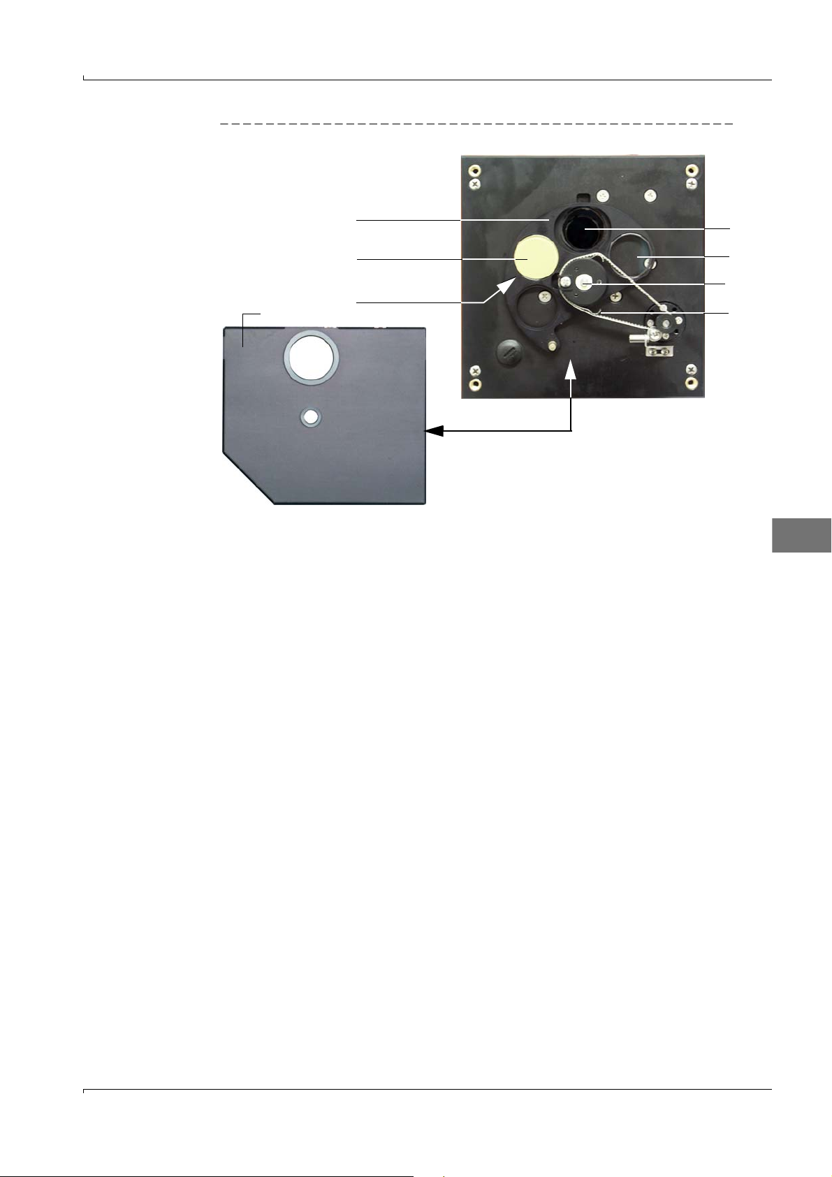
Bild 3 Reinigung der optischen Grenzflächen an der Sende-/Empfangseinheit
3
6
Nullpunktreflektor
Rückseite
1
7
5
4
2
Zahnriemen auf die Antriebsachse legen, Spannfeder zusammendrücken und
Schwenkscheibe wieder auf die Achse stecken.
D
Irrtümer und Änderungen vorbehalten
Test Equipment for DUSTHUNTER C200 · Technical Instructions · 8013686 V0.1 · © SICK AG 9
Page 10
Reflektor
3
6
5
4
2
1
Griffschrauben lösen und Elektronikeinheit zur Seite schwenken.
Montageflansch und Spülluftstutzen auf Verschmutzung kontrollieren und, falls notwendig, reinigen.
Montageflansch mit Deckel (siehe BA DUSTHUNTER C200 Abschn. 8.4) verschließen.
Im Verzeichnis „Justage / Manuelle Justage / Motorsteuerung“ bei „Position Schwenkscheibe Reflektor” die Schaltfläche „Montage” betätigen (
Die Schwenkscheibe wird damit in die Reinigungsposition bewegt.
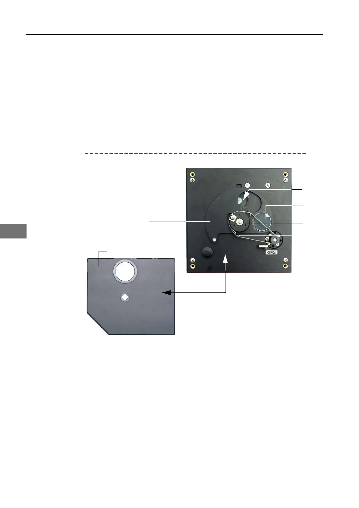
Schwenkscheibenabdeckung (1) abnehmen, die Spannfeder (2) lösen und die
Schwenkscheibe (3) von der Achse (4) abziehen.
Glasscheibe (5) (beidseitig) und Reflektoroptik (6) vorsichtig mit einem Optiktuch reinigen.
Bild 4 Reinigung der optischen Grenzflächen am Reflektor
Bild2).
D
Zahnriemen auf die Antriebsachse legen, Schwenkscheibe auf die Achse stecken und
die Spannfeder wieder anbringen.
Streulichtempfänger
Feder (1) zur Seite drücken, Bügel (2) nach vorn ziehen und Streulichtempfangsoptik
(3) aus dem Tubus ziehen.
Montageflansch (4) mit Deckel (siehe BA DUSTHUNTER SF100 Abschn. 8.4) verschließen.
Beim Streulichtempfänger für große Messstrecken die Spanner (5) öffnen und Vorsatz
(6) abnehmen.
Linse der Streulichtempfangsoptik (7) und Optik für Reflektor (8) vorsichtig mit einem
Optiktuch reinigen.
Lichtfalle (9) und O-Ring (10) kontrollieren und, falls notwendig, reinigen.
Irrtümer und Änderungen vorbehalten
10 Test Equipment for DUSTHUNTER C200 · Technical Instructions · 8013686 V 0.1 · © SICK AG
Page 11
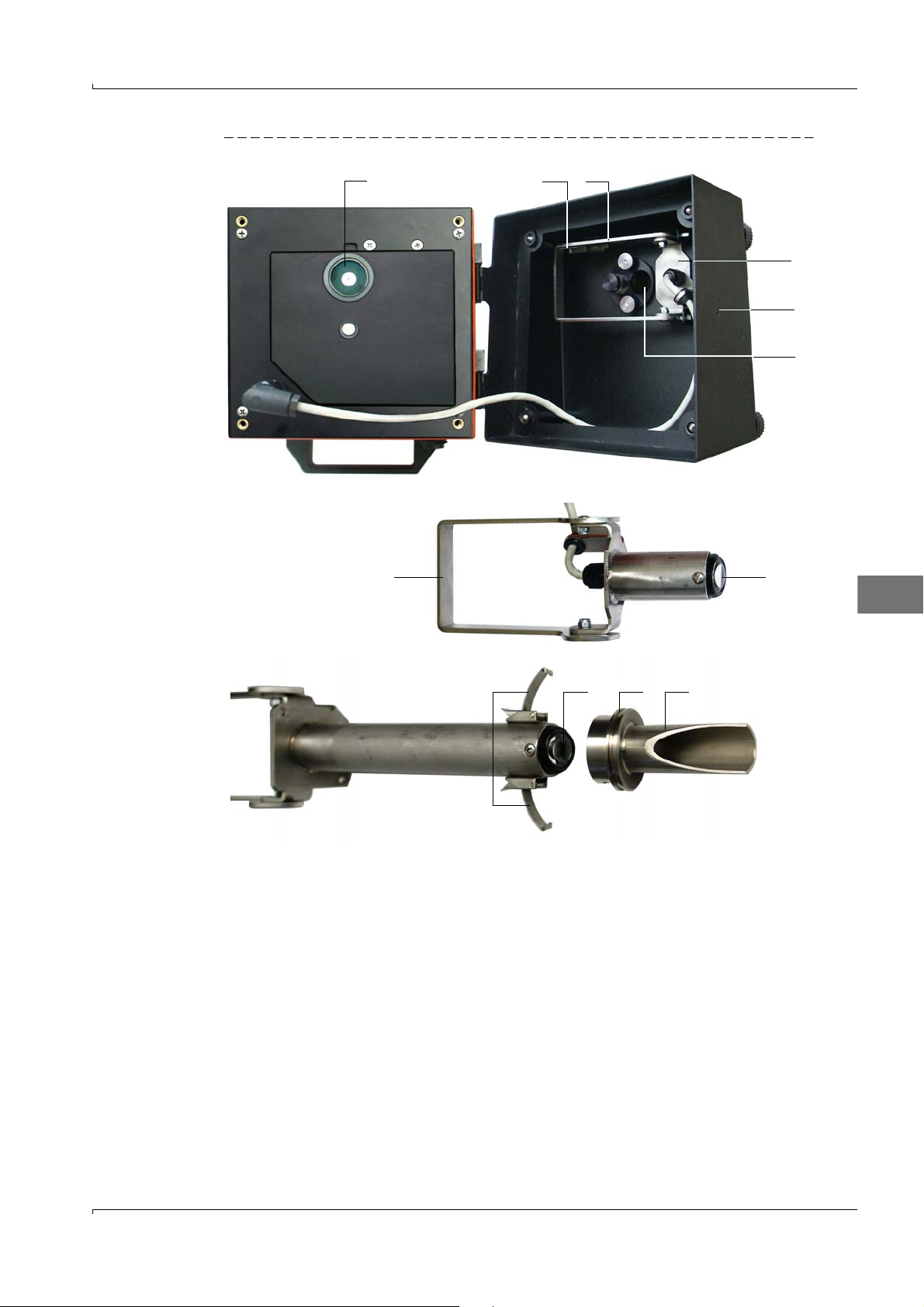
Bild 5 Reinigung der optischen Grenzflächen
57106
Streulichtempfänger für kleine Messtrecken
Streulichtempfänger für große Messtrecken
812
27
3
4
9
D
1.2.3
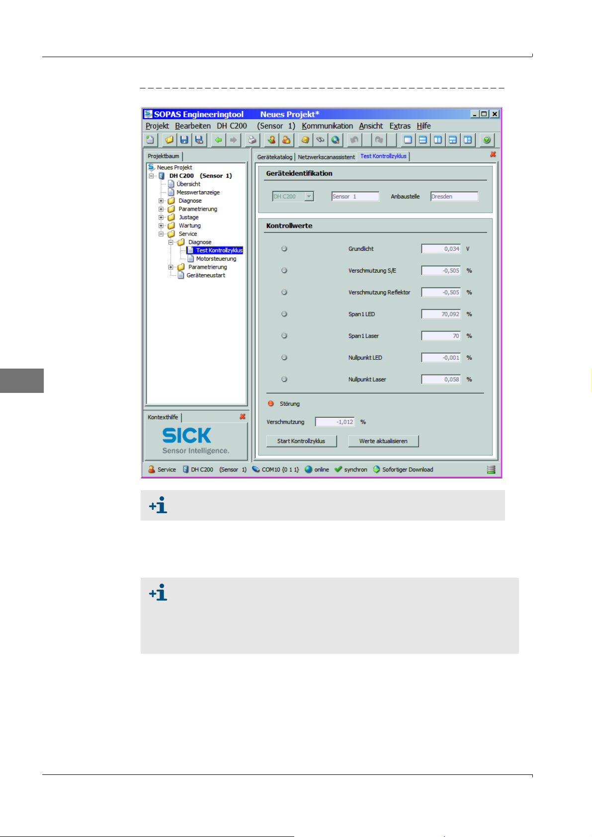
Verschmutzung kontrollieren
Kontrollzyklus auslösen, dazu:
– Passwort Ebene 2 wählen und Passwort „service” eingeben.
– In der Gerätedatei „DH C200” das Verzeichnis „Service / Diagnose / Test Kontroll-
zyklus” aufrufen und im Feld „Kontrollwerte” die Schaltfläche „Start Kontrollzyklus”
betätigen.
Irrtümer und Änderungen vorbehalten
Test Equipment for DUSTHUNTER C200 · Technical Instructions · 8013686 V0.1 · © SICK AG 11
Page 12
D
Bild 6 Unterverzeichnis „Service / Diagnose / Test Kontrollzyklus”
Der Kontrollzyklus kann auch über das LC-Display an der MCU ausgelöst
werden (siehe BA DUSTHUNTER C200 Abschn. 4.6.2).
Die gemessenen Werte für Verschmutzung, Nullpunkt und Span Laser durch Betätigen
der Schaltfläche „Werte aktualisieren” in das Gerät übernehmen wenn sie innerhalb
der zulässigen Bereiche liegen; falls nicht, Reinigung wiederholen und Verschmutzungswert durch erneutes Auslösen eines Kontrollzyklus noch mal kontrollieren.
Der Verschmutzungswert kann auch am LC-Display der MCU angezeigt
werden (Kontrollzyklus auslösen und in das Menü „C200/Diagnose”
wechseln, siehe BA DUSTHUNTER C200 Abschn. 4.6.2).
Wenn der Verschmutzungswert auch nach mehrfacher Reinung nicht unter
den Wert für Warnung sinkt, liegt wahrscheinlich ein Gerätedefekt vor →
SICK Service kontaktieren.
Schwenkscheibe in Messposition fahren (im Verzeichnis „Justage / Manuelle Justage /
Motorsteuerung“ (
S.8, Bild2) die Schaltfläche „Messbetrieb” betätigen) und Schwenk-
scheibenabdeckung wieder an der Sende-/Empfangseinheit anbringen.
12 Test Equipment for DUSTHUNTER C200 · Technical Instructions · 8013686 V 0.1 · © SICK AG
Irrtümer und Änderungen vorbehalten
Page 13
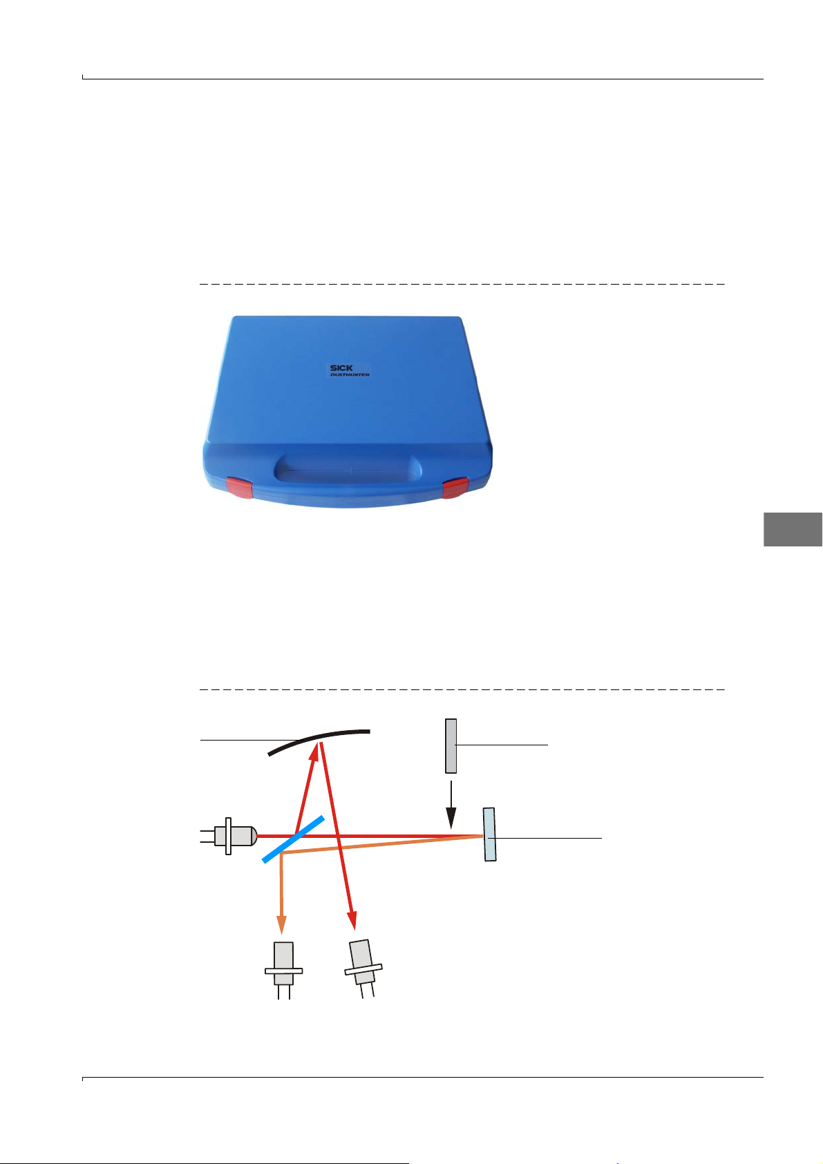
2 Linearitätskontrolle
Kontrollfilter
Kontrollreflektor
Sende-LED
Mess- Monitorempfänger empfänger
Hohlspiegel
2.1 Grundlagen, allgemeine Hinweise
Die Linearität von Transmissions- und Streulichtmessung mit dem DUSTHUNTER C200
wird durch Messung verschiedener, definierter Transmissionswerte überprüft. Die dazu
erforderlichen Teile sind in einem Kontrollfilterset zusammengefasst.
Die Sende-/Empfangseinheit muss zur Linearitätskontrolle nicht vom Kanal abgebaut
werden.
Bild 7 Koffer für Linearitätsprüfmittel
2.1.1
Messprinzip
Transmissionsmessung
An der Sende-/Empfangseinheit wird in den Strahlengang ein Kontrollreflektor eingebracht
und danach der Transmissionswert auf 100 % normiert. Anschließend werden nacheinander Kontrollfilter mit unterschiedlicher, definierter Transmission in den Strahlengang
eingesetzt. Wenn der vom DUSTHUNTER T gemessene Wert und der Wert des jeweils
verwendeten Kontrollfilters miteinander unter Berücksichtigung der zulässigen Toleranz
übereinstimmen, ist die Linearität der Messsung gewährleistet.
Bild 8 Prinzipielle Anordnung für Linearitätsmessung
D
Irrtümer und Änderungen vorbehalten
Test Equipment for DUSTHUNTER C200 · Technical Instructions · 8013686 V0.1 · © SICK AG 13
Page 14
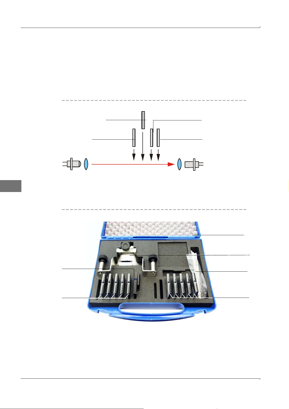
Streulichtmessung
Sender Empfänger
Streuscheibe 1 Streuscheibe 2
Kontrollfilter Dämpfungsscheibe
Transportkoffer
Filterhalter für
Streulichtmessung
Wattestäbchen
Kontrollfilter für
Streulichtmessung
Filterhalter für
Transmissionsmessung
Kontrollfilter für
Transmissionsmessung
Zur Linearitätskontrolle wird der Laserstrahl direkt auf den Streulichtempfänger gerichtet.
In das optische Messvolumen werden zwei Streuscheiben und ein Dämpfungsfilter
eingesetzt. Dadurch wird ein Streulichtmesswert simuliert, der auf 100 % normiert wird.
Durch anschließendes Einfügen von Kontrollfiltern mit unterschiedlicher, definierter Transmission wird der normierte Streulichtmesswert verringert. Wenn der vom DUSTHUNTER
SF100 gemessene Wert und der Wert des jeweils verwendeten Kontrollfilters miteinander
unter Berücksichtigung der zulässigen Toleranz übereinstimmen, ist die Linearität der
Messsung gewährleistet.
Bild 9 Prinzipielle Anordnung für Linearitätsmessung
D
2.1.2 Komponenten
Das Linearitätsprüfmittel besteht aus einem Transportkoffer mit Filterhalter, 5 St. Kontrollfilter mit ca. 0 %, 20 %, 40 %, 60 % und 80 % Transmission, einem Adapterkabel und
einem Reinigungsset.
Bild 10 Komponenten des Linearitätsprüfmittels
14 Test Equipment for DUSTHUNTER C200 · Technical Instructions · 8013686 V 0.1 · © SICK AG
Irrtümer und Änderungen vorbehalten
Page 15

2.1.3 Wichtige Hinweise zur Handhabung
Alle Teile des Kontrollfiltersets sind pfleglich zu handhaben.
Vor Benutzung jedes Kontrollfilters ist zu gewährleisten, dass die optisch aktive Fläche
sauber ist. Dazu gilt:
– Die optisch aktiven Flächen nicht mit den Fingern berühren.
– Bei Erfordernis die optisch aktive Fläche mit dem beiliegenden Optiktuch reinigen
(bei hartnäckigen Verschmutzungen Alkohol und Wasser benutzen).
– Staub und Fusseln mit Wattestäbchen entfernen.
Für Filtergläser mit Kratzern im Bereich der optisch aktiven Fläche wird keine Gewährleistung für die Richtigkeit des Filterwertes übernommen. Solche Kontrollfilter müssen
ersetzt werden.
Um Beschädigungen und Verschmutzungen zu vermeiden, sind die Teile immer im
geschlossenen Transportkoffer aufzubewahren.
D
Irrtümer und Änderungen vorbehalten
Test Equipment for DUSTHUNTER C200 · Technical Instructions · 8013686 V0.1 · © SICK AG 15
Page 16
2.2 Linearität überprüfen
Das Messsystem mindestens 30 min vor Beginn der Linearitätsprüfung
einschalten.
2.2.1 Transmissionsmessung
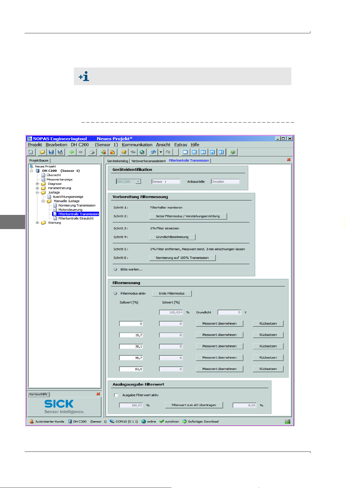
In der Gerätedatei „DH C200” das Unterverzeichnis „Justage / Manuelle Justage / Filterkontrolle Transmission“ wählen.
Bild 11 Menü „Justage / Manuelle Justage / Filterkontrolle Transmission“
D
16 Test Equipment for DUSTHUNTER C200 · Technical Instructions · 8013686 V 0.1 · © SICK AG
Irrtümer und Änderungen vorbehalten
Page 17
2
1
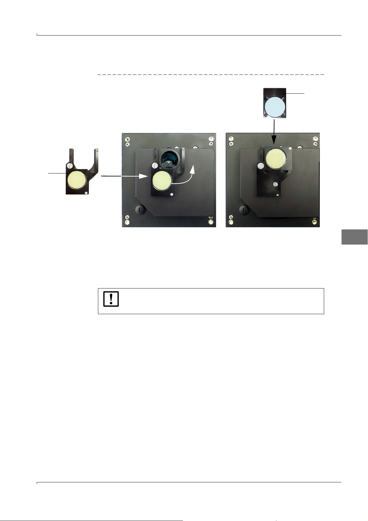
Filterhalter mit Kontrollreflektor (1) an der Sende-/Empfangseinheit gemäß Bild 12 aufsetzen und Kontrollreflektor in den Strahlengang schwenken.
Bild 12 Kontrollfilter einsetzen
Nacheinander die in der Gruppe „Vorbereitung Filtermessung” angezeigten Schritte
abarbeiten. Das Messsystem wird damit für die Filtermessung temporär auf den Kontrollreflektor normiert.
Das erste Kontrollfilter (2) (z.B. mit einem Wert von ca. 20 %) in den Filterhalter einschieben und ca. 5 s warten. Der im Fenster „Istwert [%]“ angezeigte %-Wert muss mit
dem auf dem Kontrollfilter aufgetragenen Wert mit einer Toleranz von ± 2 % übereinstimmen.
D
WICHTIG:
Die Kontrollfilter müssen sauber sein. Andernfalls ist es möglich, dass die
Anzeigewerte außerhalb der Toleranz liegen.
Wenn der gemessene Wert gespeichert werden soll, die Schaltfläche „Messwert
übernehmen“ betätigen (
Linearitätstest durch Betätigen der Schaltfläche „Ende Filtermode“ beenden.
Filterhalter mit Kontrollfilter von der Sende-/Empfangseinheit entfernen und Teile im
Transportkoffer verpacken.
S.16, Bild11).
Irrtümer und Änderungen vorbehalten
Test Equipment for DUSTHUNTER C200 · Technical Instructions · 8013686 V0.1 · © SICK AG 17
Page 18
2.2.2 Streulichtmessung
12
4
3
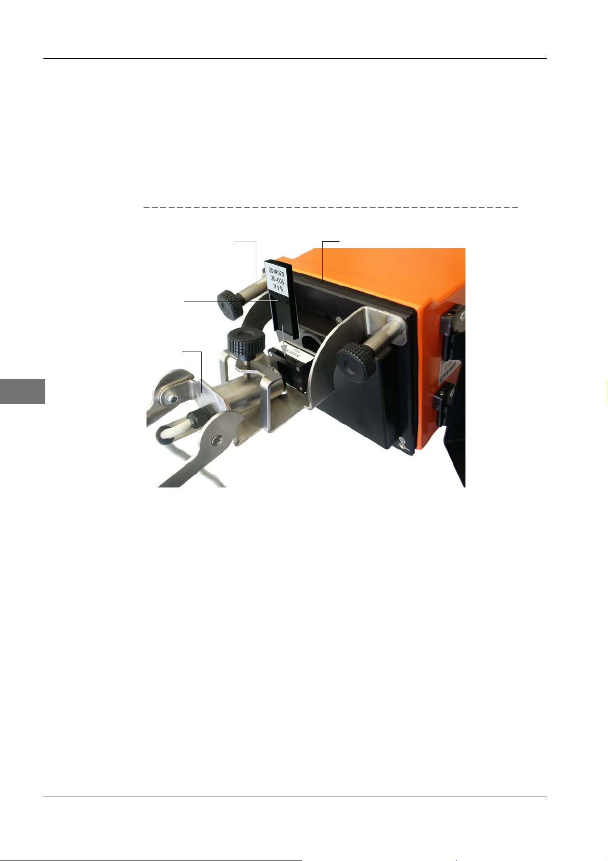
Filterhalter (1) an der Sende-/Empfangseinheit (2) anbringen.
Verbindungskabel an Sende-/Empfangseinheit und Reflektor/Streulichtempfänger lösen, Elektronikeinheit des Reflektor/Streulichtempfängers vom Montageflansch abnehmen und zur Sende-/Empfangseinheit bringen.
Streulichtempfangsoptik (3) in den Filterhalter einsetzen.
Elektronikeinheit des Reflektor/Streulichtempfängers mit der Sende-/Empfangseinheit
über das Adapterkabel verbinden.
Bild 13 Prüfkonfiguration
D
In der Gerätedatei „DH C200” das Verzeichnis „Justage / Manuelle Justage / Filterkontrolle Streulicht“ wählen und die Schaltfläche „Setze Filtermode/Referenzmessung“
betätigen.
18 Test Equipment for DUSTHUNTER C200 · Technical Instructions · 8013686 V 0.1 · © SICK AG
Irrtümer und Änderungen vorbehalten
Page 19
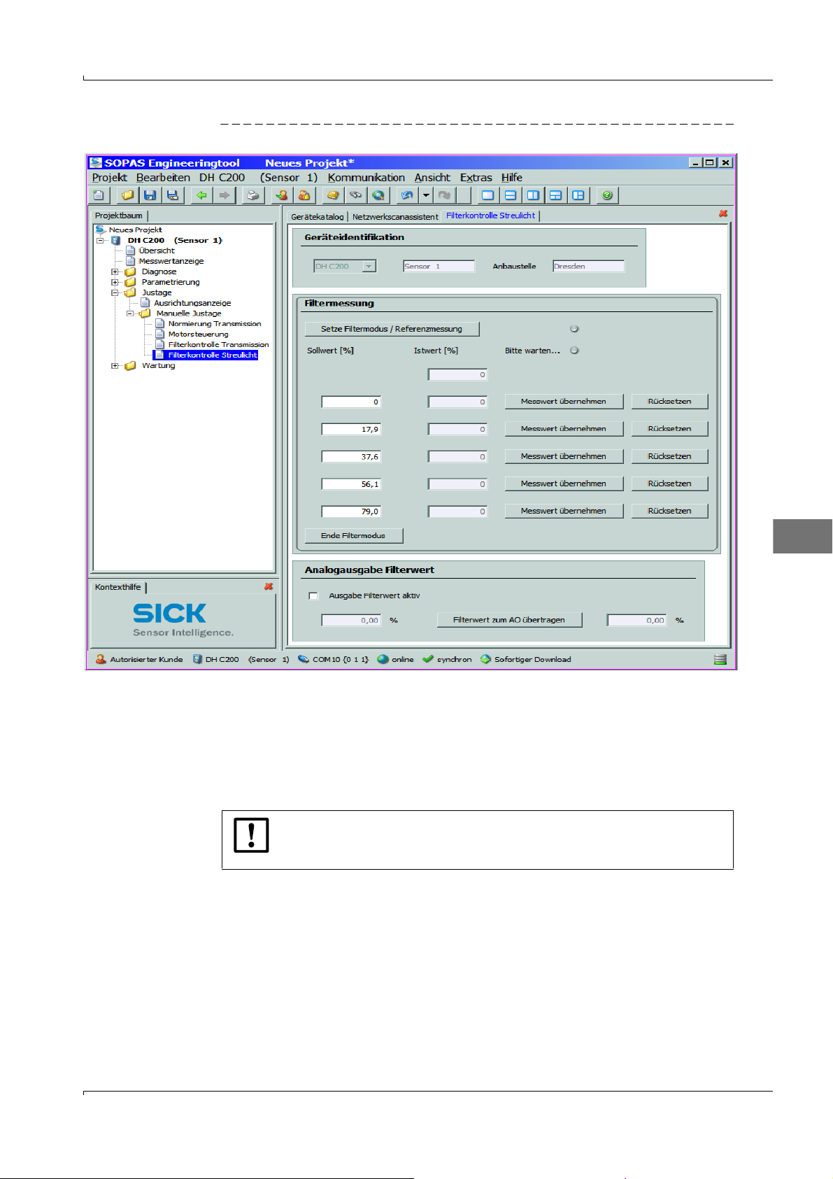
Bild 14 Verzeichnis „Justage / Manuelle Justage / Filterkontrolle Streulicht“
D
Irrtümer und Änderungen vorbehalten
Im Verzeichnis „Justage / Manuelle Justage / Filterkontrolle“ nochmal auf „Setze Filtermode/Referenzmessung“ klicken. Das Messsystem wird damit für die Filtermessung
temporär normiert.
Das erste Kontrollfilter (4) [S.18, Bild13] (z.B. mit einem Wert von ca. 20 %) in den Filterhalter einschieben und ca. 5 s warten. Der im Fenster „Istwert [%]“ angezeigte %Wert muss mit dem auf dem Kontrollfilter aufgetragenen Wert mit einer Toleranz von ±
2 % übereinstimmen.
WICHTIG:
Die Kontrollfilter müssen sauber sein. Andernfalls ist es möglich, dass die
Anzeigewerte außerhalb der Toleranz liegen.
Wenn der gemessene Wert gespeichert werden soll, die Schaltfläche „Messwert
übernehmen“ betätigen.
Den gleichen Ablauf mit den anderen Kontrollfiltern wiederholen.
Linearitätstest durch Betätigen der Schaltfläche „Ende Filtermode“ beenden.
Test Equipment for DUSTHUNTER C200 · Technical Instructions · 8013686 V0.1 · © SICK AG 19
Page 20

2.3 Linearitätstest beenden
Adapterkabel von Sende-/Empfangseinheit und Elektronikeinheit des Reflektor/Streulichtempfängers lösen.
Streulichtempfangsoptik aus dem Filterhalter ausbauen.
Elektronikeinheit des Reflektor/Streulichtempfängers am Montageflansch anbringen.
Deckel vom Montageflansch abnehmen und Streulichtempfangsoptik wieder einbauen.
Elektronikeinheit zurück schwenken und mit den Griffschrauben arretieren.
Verbindungskabel wieder an Sende-/Empfangseinheit und Reflektor/Streulichtempfänger anschließen.
Filterhalter von der Sende-/Empfangseinheit abbauen, Deckel vom Montageflansch
abnehmen, Elektronikeinheit zurück schwenken und mit den Griffschrauben arretieren.
Filterhalter und Kontrollfilter im Transportkoffer verpacken.
Messbetrieb wieder aufnehmen und und Programm SOPAS ET schließen.
D
20 Test Equipment for DUSTHUNTER C200 · Technical Instructions · 8013686 V 0.1 · © SICK AG
Irrtümer und Änderungen vorbehalten
Page 21

D
Irrtümer und Änderungen vorbehalten
Test Equipment for DUSTHUNTER C200 · Technical Instructions · 8013686 V0.1 · © SICK AG 21
Page 22

Content
1 General Notes . . . . . . . . . . . . . . . . . . . . . . . . . . . . . . . . . . . . . . . . . . . . . . . . . . . . . . . . . 24
1.1 Main hazards . . . . . . . . . . . . . . . . . . . . . . . . . . . . . . . . . . . . . . . . . . . . . . . . . . . . . . . . . . . . . . . 24
1.2 Preparation work. . . . . . . . . . . . . . . . . . . . . . . . . . . . . . . . . . . . . . . . . . . . . . . . . . . . . . . . . . . . 25
1.2.1 Setting the measuring system to "Maintenance" mode . . . . . . . . . . . . . . . . . . . . . . . 25
1.2.2 Cleaning the optical surfaces . . . . . . . . . . . . . . . . . . . . . . . . . . . . . . . . . . . . . . . . . . . . . . 26
1.2.3 Checking the contamination . . . . . . . . . . . . . . . . . . . . . . . . . . . . . . . . . . . . . . . . . . . . . . . 29
2 Linearity check. . . . . . . . . . . . . . . . . . . . . . . . . . . . . . . . . . . . . . . . . . . . . . . . . . . . . . . . 31
2.1 Bases, general information. . . . . . . . . . . . . . . . . . . . . . . . . . . . . . . . . . . . . . . . . . . . . . . . . . . 31
2.1.1 Measuring principle . . . . . . . . . . . . . . . . . . . . . . . . . . . . . . . . . . . . . . . . . . . . . . . . . . . . . . . 31
2.1.2 Components . . . . . . . . . . . . . . . . . . . . . . . . . . . . . . . . . . . . . . . . . . . . . . . . . . . . . . . . . . . . . 32
2.1.3 Important information for handling . . . . . . . . . . . . . . . . . . . . . . . . . . . . . . . . . . . . . . . . . 33
2.2 Checking the linearity. . . . . . . . . . . . . . . . . . . . . . . . . . . . . . . . . . . . . . . . . . . . . . . . . . . . . . . . 34
2.2.1 Transmission measurement . . . . . . . . . . . . . . . . . . . . . . . . . . . . . . . . . . . . . . . . . . . . . . . 34
2.2.2 Scattered light measurement . . . . . . . . . . . . . . . . . . . . . . . . . . . . . . . . . . . . . . . . . . . . . . 36
2.3 Terminating the linearity test . . . . . . . . . . . . . . . . . . . . . . . . . . . . . . . . . . . . . . . . . . . . . . . . . 38
E
22 Test Equipment for DUSTHUNTER C200 · Technical Instructions · 8013686 V0.1 · © SICK AG
Subject to change w ithout notice
Page 23

Test Equipment for DUSTHUNTER C200
Linearity Check
General Notes
Linearity check
E
Subject to change w ithout notice
Test Equipment for DUSTHUNTER C200 · Technical Instructions · 8013686 V0.1 · © SICK AG 23
Page 24
1 General Notes
About this document
This instruction describes the use of the test equipment for the linearity check of the dust
concentration monitors DUSTHUNTER C200. The instruction is valid only in conjunction
with the accompanying Operating Instructions (OI).
NOTICE:
Always read this manual carefully before carrying out any work on the
equipment. Always observe warnings and comply with all safety instructions.
1.1 Main hazards
Hazards from hot and/or aggressive gases and/or high pressure
The sender/receiver unit is fitted directly on the gas-carrying duct. Observe all valid
regulations and plant safety notices for all work on the measuring system and take
suitable protective measures.
WARNING: Danger from exhaust gas
Take special protective measures for plants with gases detrimental to
health, high pressure, high temperatures when opening the device.
Hazards through laser beam
E
WARNING: Hazards through laser beam
Never look directly into the beam path
Do not point the laser beam at persons
Pay attention to laser beam reflections.
24 Test Equipment for DUSTHUNTER C200 · Technical Instructions · 8013686 V 0.1 · © SICK AG
Subject to change w ithout notice
Page 25
1.2 Preparation work
1.2.1 Setting the measuring system to "Maintenance" mode
Take the following steps to set the measuring system to "Maintenance" mode before
starting the work described below.
Connect the measuring system via laptop/PC to the SOPAS ET program and click "Network Scan" in the "Network Scan Assistant" directory.
Select the "MCU" device file in the "Network Scan Assistant / Detected devices" tab and
move to the "Project Tree" window (see OI DUSTHUNTER C200, Section 4.1.4).
Enter the level 1 password (see OI DUSTHUNTER C200, Section 4.1.4).
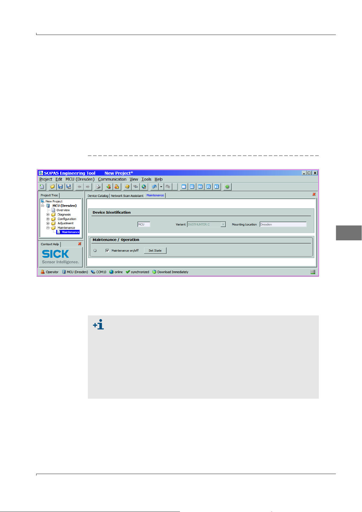
Select the "Maintenance/Maintenance" subdirectory, activate the "Maintenance on/off"
checkbox in the "Maintenance / Operation" group and click "Set State" (see
Figure1 Setting "Maintenance" mode
Fig.1).
Select the "DH C200"device file in the "Network Scan Assistant / Detected devices" tab
and move to the "Project Tree" window .
Enter the level 1 password and set the sender/receiver unit to "Maintenance" mode.
The "Maintenance" mode can also be set by using the keys on the LC
display of the MCU (see OI DUSTHUNTER C200, Section 4.6.2) or
connecting an external maintenance switch to the terminals for Dig In2 (17,
18) in the MCU (see OI DUSTHUNTER C200, Section 3.3.4).
During "Maintenance", a check cycle is not performed.
The value set for "Maintenance" is output at the analog output (see OI
DUSTHUNTER C200, Section 4.3.4). This also applies if a malfunction
exists (signalised at the relay output).
The "Maintenance" state is reset when there is a voltage failure. In this
case, the measuring system switches automatically to "Measurement" after
the operating voltage is switched on again.
E
Subject to change w ithout notice
Test Equipment for DUSTHUNTER C200 · Technical Instructions · 8013686 V0.1 · © SICK AG 25
Page 26
1.2.2 Cleaning the optical surfaces
Sender/receiver unit
Loosen the knurled screws and swivel the electronics unit to the side.
Check assembly flange and purge air nozzle for contamination, and clean if necessary.
Lock the assembly flange with cover (see OI DUSTHUNTER C200 Section 8.4).
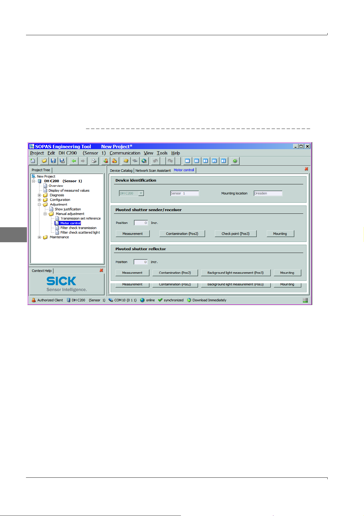
Open the "Adjustment / Manual Adjustment / Motor Control " directory in the "DH
C200" device file and click "Mounting" at "Pivoted shutter sender/receiver".
The swivel plate moves then to the cleaning position.
Figure2 "Adjustment / Manual Adjustment / Motor control" directory
E
Remove swivel plate cover (1), press the tension spring (2) and take swivel plate (3) off
the axis (4).
Carefully clean glass pane (5) (both sides), zero point reflector (6) and sender optics (7)
with an optics cloth.
26 Test Equipment for DUSTHUNTER C200 · Technical Instructions · 8013686 V 0.1 · © SICK AG
Subject to change w ithout notice
Page 27
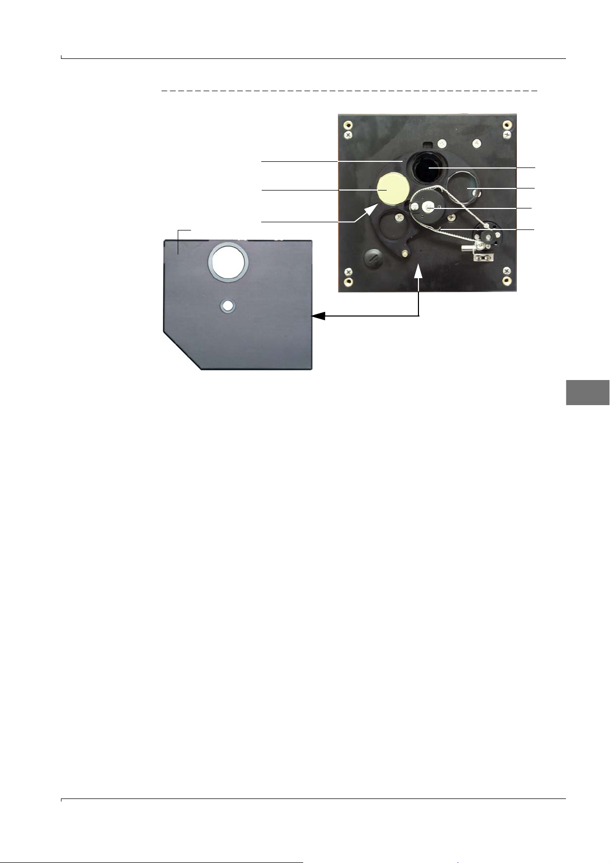
Figure3 Cleaning the optical interfaces on the sender/receiver unit
3
6
Zero point reflector,
rear side
1
7
5
4
2
Lay the toothed belt on the drive axis, press the the tension spring and push the swivel
plate back onto the axis.
E
Subject to change w ithout notice
Test Equipment for DUSTHUNTER C200 · Technical Instructions · 8013686 V0.1 · © SICK AG 27
Page 28
Reflector
3
6
5
4
2
1
Loosen the knurled screws and swivel the housing to the side.
Check assembly flange and purge air nozzle for contamination, and clean if necessary.
Lock the assembly flange with cover (see OI DUSTHUNTER T Section 8.4).
Click "Mounting" at "Pivoted shutter reflector" in the "Adjustment / Manual adjustment /
Motor control “ directory and (
p.26, Fig.2).
The swivel plate moves then to the cleaning position.
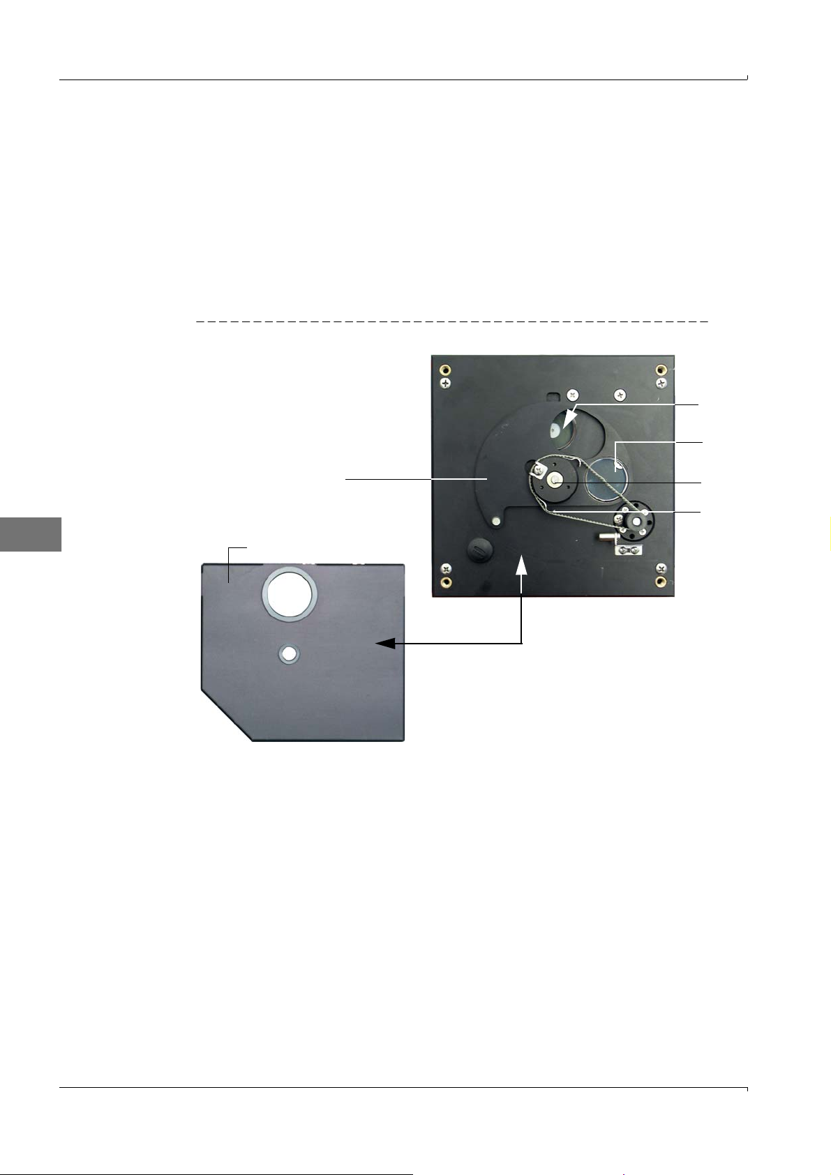
Remove the swivel plate cover (1), press the tension spring (2) and take the swivel plate
(3) off the axis (4).
Carefully clean glass pane (5) (both sides) and reflector optics (6) with an optics cloth.
Figure 4 Cleaning the optical interfaces on the reflector/scattered light receiver
E
Lay the toothed belt on the drive axis, press the the tension spring and push the swivel
plate back onto the axis.
Scattered light receiver
Press the spring (1) to the side, pull the clamp (2) to the front and pull the scattered
light receiver optic (3) carefully out of the tubus.
Lock the assembly flange with cover (see OI DUSTHUNTER C200 Section. 8.4) .
Open the grips (5) at the scattered light receiver optic for large measuring distances
and remove the attachment (6).
Carefully clean the lens of the scattered light receiver (6) and reflector optics (7) with
an optics cloth.
Check ligth trap (9) and O ring (10), and clean if necessary..
Subject to change w ithout notice
28 Test Equipment for DUSTHUNTER C200 · Technical Instructions · 8013686 V 0.1 · © SICK AG
Page 29
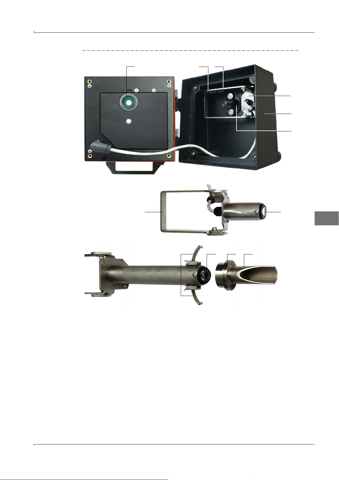
Figure5 Cleaning the optical interfaces on the scattered light receiver
57106
Scattered light receiver for short measuring distances
Scattered light receiver for long measuring distances
812
27
3
4
9
E
1.2.3
Checking the contamination
Initiate a check cycle:
– Select the password level 2 and enter password "service”.
– Select the "Service / Diagnosis / Check cycle test” subdirectory (”DH C200” device
file) and click "Start check cycle" in the "Check values”group.
Subject to change w ithout notice
Test Equipment for DUSTHUNTER C200 · Technical Instructions · 8013686 V0.1 · © SICK AG 29
Page 30
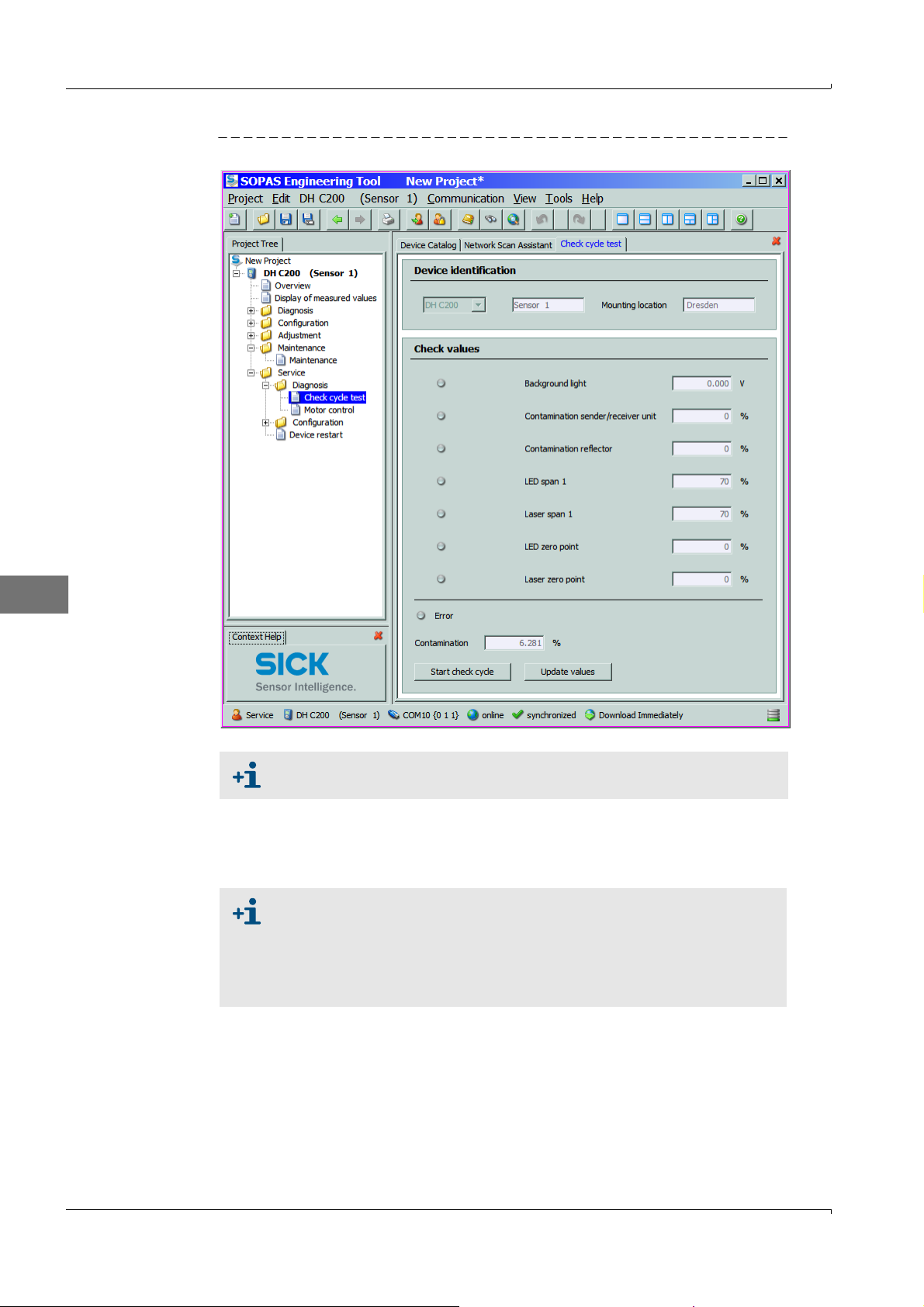
Figure6 Service / Diagnosis / Check cycle test” subdirectory
E
The check cycle can also be triggered by using the keys on the LC display of
the MCU (see OI DUSTHUNTER C200, Section 4.6.2).
Store the measured values for contamination, zero point and span in the device by
clicking "Update values" ("Check values" group) if they are within the allowed range; if
not, repeat cleaning and check once more the contamination value by triggering a
renewed check cycle.
The contamination value can also be displayed on the LC display of the
MCU (initiate a check cycle and switch to the "C200/Diagnosis" menu;
see OI DUSTHUNTER C200, Section 4.6.2).
If the contamination value does not sink below the value for warning in
spite of several cleaning processes, the device is probably defective →
contact the SICK Service.
Move the swivel plate back into the measuring position (click "Measurement" in the
"Adjustment / Manual adjustment / Motor control“ directory ;
p.26, Fig.2) and put the
swivel plate cover back on the sender/receiver unit
Subject to change w ithout notice
30 Test Equipment for DUSTHUNTER C200 · Technical Instructions · 8013686 V 0.1 · © SICK AG
Page 31
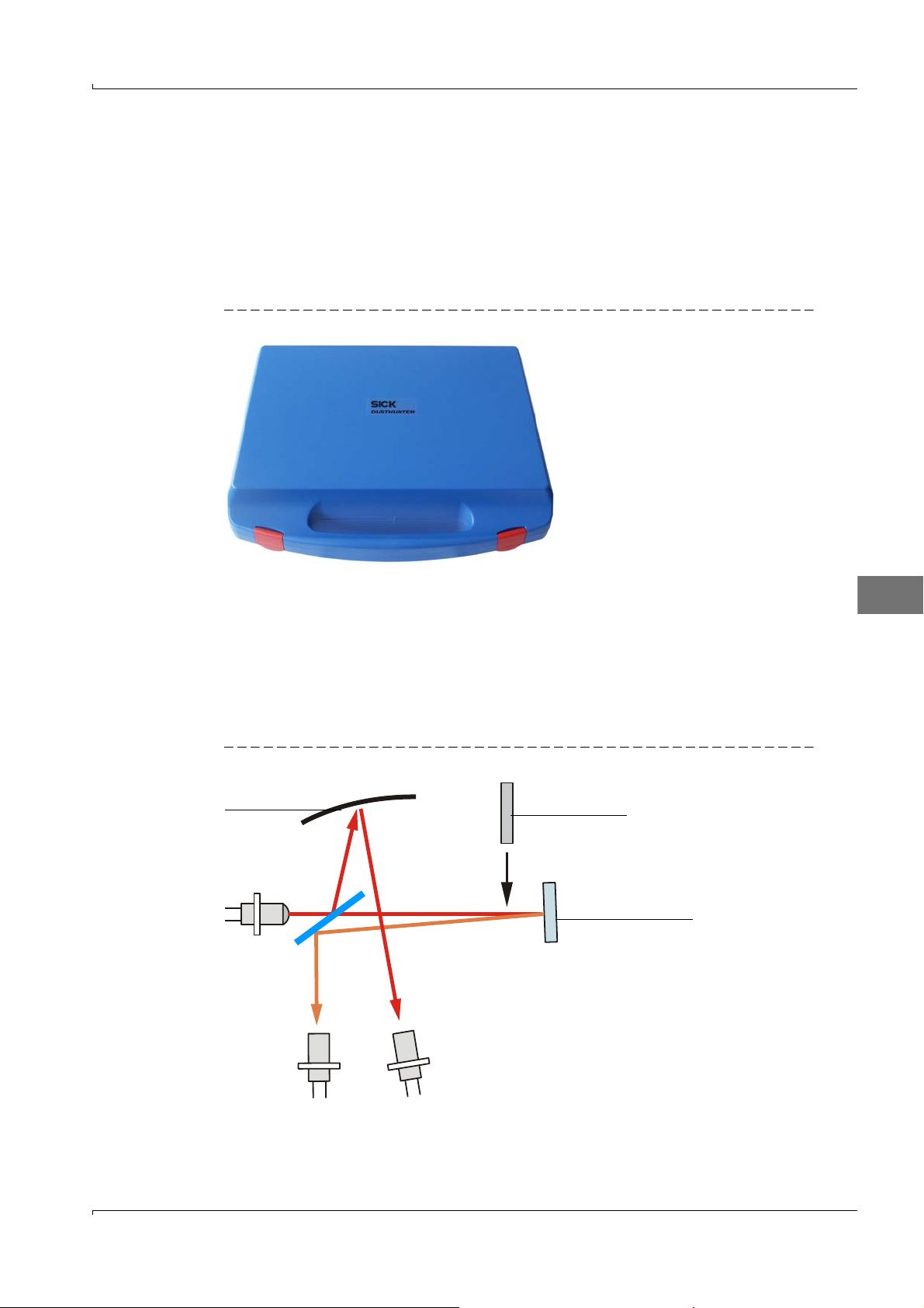
2 Linearity check
Control filter
Control reflector
Sender LED
Measurement Monitor
receiver receiver
Concave mirror
2.1 Bases, general information
The linearity of transmission and scattered light measurement with the DUSTHUNTER
C200 is checked by measuring different defined transmission values. The required parts
are combined in a control filter set.
The sender/receiver unit must not be removed from the duct to check the linearity.
Figure7 Case for test equipment for linearity test
2.1.1
Measuring principle
Transmission measurement
A control reflector is installed in the beam path on the sender/receiver unit and then the
transmission value scaled to 100%. Control filters with different defined transmission are
then successively inserted in the beam path. If the value measured by DUSTHUNTER T and
the value of the respective control filter used match, under consideration of the allowed
tolerance, linearity of the measurement is ensured.
Figure 8 Layout principle for linearity measurement
E
Subject to change w ithout notice
Test Equipment for DUSTHUNTER C200 · Technical Instructions · 8013686 V0.1 · © SICK AG 31
Page 32
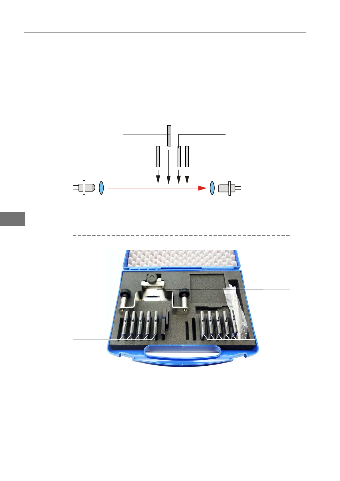
Scattered light measurement
Sender Reciever
Scattering screen 1 Scattering screen 2
Control filter Damping screen
Filter bracket for
transmission
measurement
Control filter for
transmission
measurement
Transport case
Filter bracket for
scattered light
measurement
Cotton swabs
Control filter for
scattered light
measurement
For linearity checkl the laser beam is turned directly towards the scattered light receiver.
Two scattering screens and a damping filter are inserted in the optical measuring volume.
This simulates a scattered light measured value scaled to 100%. The following insertion of
control filters with different, defined transmission reduces the scaled scattered light
measured value. If the value measured by DUSTHUNTER C200 and the value of the
respective control filter used match, under consideration of the allowed tolerance, linearity
of the measurement is ensured.
Figure9 Layout principle for linearity measurement
2.1.2 Components
E
The equipment for the linearity test consists of a transport case with filter bracket, 5
control filters with approx. 0%, 20%, 40%, 60% and 80% transmission and a cleaning set.
Figure10 Components of the equipment for the linearity test
Subject to change w ithout notice
32 Test Equipment for DUSTHUNTER C200 · Technical Instructions · 8013686 V 0.1 · © SICK AG
Page 33

2.1.3 Important information for handling
All parts of the control filter set must be handled with care.
Ensure that the optically active surface is clean before using a control filter. This
implies:
– Do not touch the optically active surfaces with your fingers.
– If necessary, clean the optically active surface with the enclosed optics cloth (use
alcohol and water for adhering contamination).
– Remove dust and fluff with cotton swabs.
There is no warranty for the correctness of the filter value when filter glasses with
scratches in the area of the optically active surface are used. Such control filters must
be replaced.
Always keep the parts in the closed transport case to prevent damage and contamination.
E
Subject to change w ithout notice
Test Equipment for DUSTHUNTER C200 · Technical Instructions · 8013686 V0.1 · © SICK AG 33
Page 34
2.2 Checking the linearity
Switch the measuring system on at least 30 min. before starting the linearity
test.
2.2.1 Transmission measurement
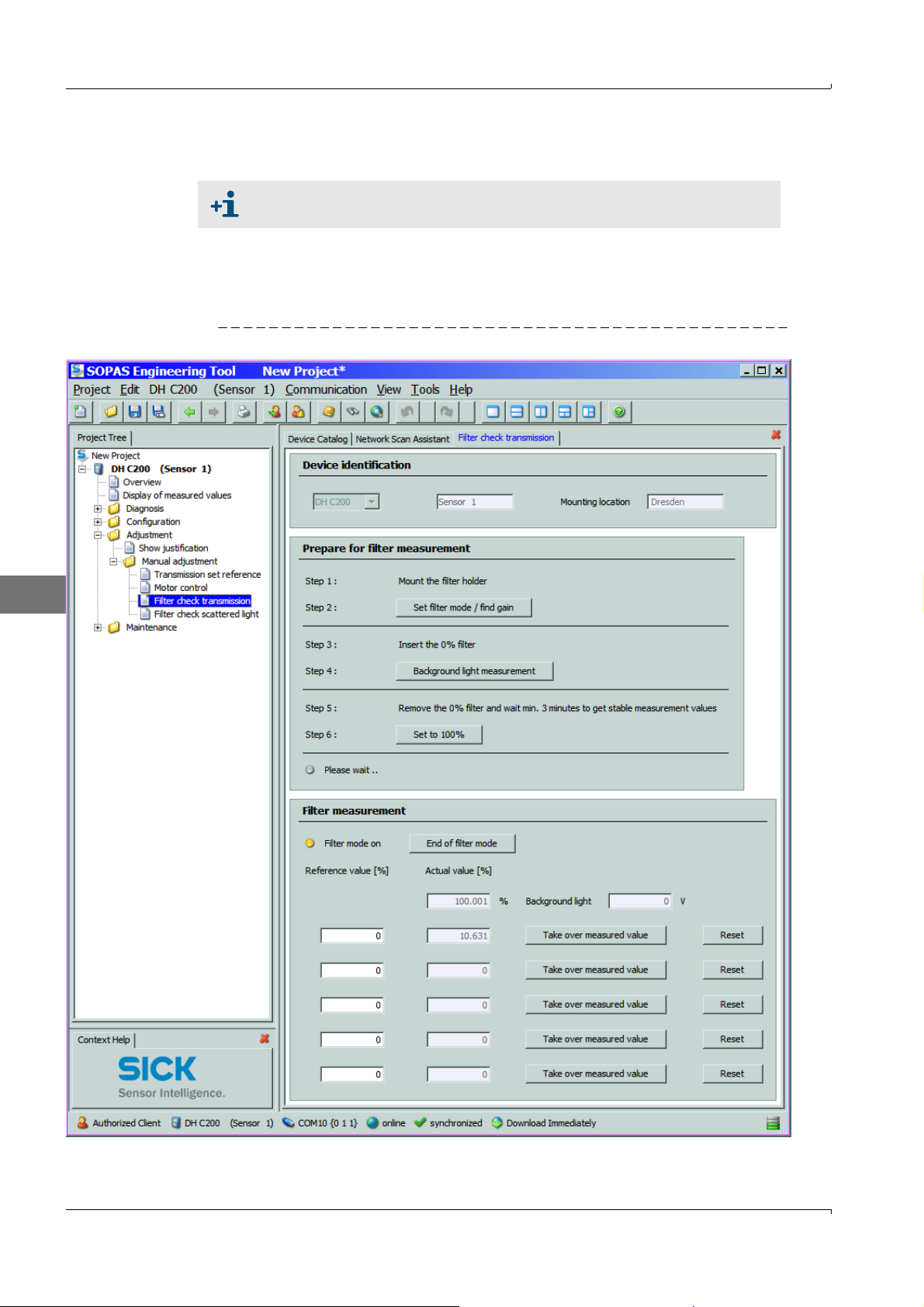
Select the "Adjustment / Manual adjustment / Filter check transmission" subdirectory
in the "DH C200” device file.
Figure 11 "Adjustment / Manual adjustment / Filter check transmission" menu )
E
34 Test Equipment for DUSTHUNTER C200 · Technical Instructions · 8013686 V 0.1 · © SICK AG
Subject to change w ithout notice
Page 35
2
1
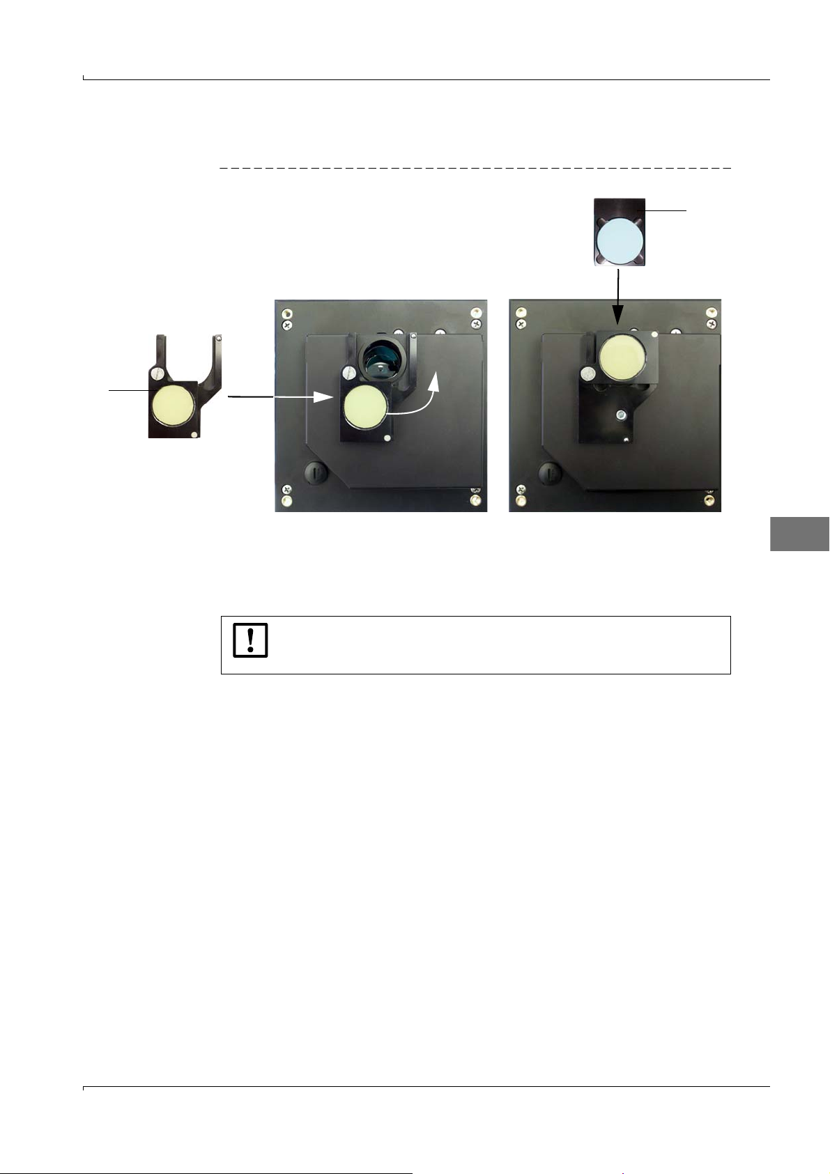
Place the filter holder with control reflector (1) on the sender/receiver unit according to
fig.12 and swivel the control reflector into the beam path.
Figure12 Inserting the control filter
Carry out the steps in the group "Prepare for filter measurement" after each other . This
scales the measuring system temporarily to the control reflector for filter measurement.
Insert the first control filter (2) (e.g. with a value of approx. 20%) in the filter holder and
wait for approx. 5 s. The value displayed in the "Actual value [%]" window must match
the value printed on the control filter with a tolerance of ± 2%.
E
NOTICE:
The control filters must be clean. Otherwise it is possible that the displayed
values are outside the tolerance.
If the measured value is to be saved, click "Take over measured value" (p.34, Fig.11)
Repeat the same sequence with the other control filters.
Terminate the linearity test by clicking "End Filter mode".
Remove the filter holder with control filters from the sender/receiver unit and pack the
parts in the transport case.
Subject to change w ithout notice
Test Equipment for DUSTHUNTER C200 · Technical Instructions · 8013686 V0.1 · © SICK AG 35
Page 36
2.2.2 Scattered light measurement
12
4
3
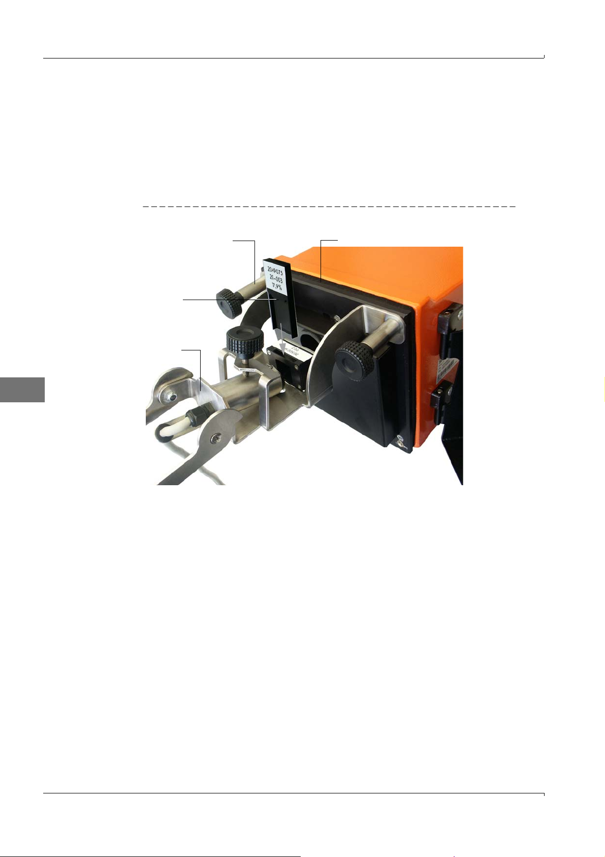
Assemble the filter bracket (1) on the sender/receiver unit (2).
Disconnect the connection cable from sender/receiver unit and reflector/scattered
light receiver, remove the electronics unit of the reflector/scattered light receiver from
the assembly flange and bring it to the sender/receiver unit.
Put the scattered light receiver optic (3) into the filter bracket.
Connect the electronics unit of the scattered light receiver to the sender/receiver unit
using the adapter cable.
Figure13 Test configuration
E
Select the "Adjustment / Manual adjustment / Filter check scattered light" subdirectory
in the "DH C200” device file and click "Set filter mode/ reference measurement".
36 Test Equipment for DUSTHUNTER C200 · Technical Instructions · 8013686 V 0.1 · © SICK AG
Subject to change w ithout notice
Page 37
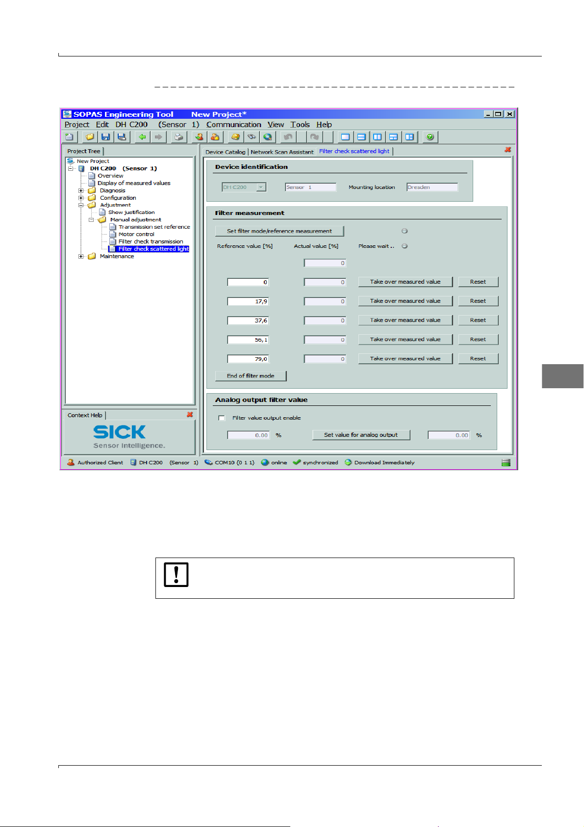
Figure14 "Adjustment / Manual adjustment / Filter check scattered light" subdirectory
E
Click "Set filter mode/ reference measurement" in the "Adjustment / Manual adjustment / Filter check scattered light" subdirectory again. This scales the measuring system temporarily for filter measurement.
Insert the first control filter (4) [p.36, Fig.13] (e.g. with a value of approx. 20%) in the
filter bracket, and wait for approx. 5 s. The value shown in the "Actual value" window
must match the value applied to the control filter with a tolerance of ± 2%.
NOTICE:
The control filters must be clean. Otherwise the displayed values could be
outside the tolerance.
If the measured value is to be saved, click "Take over measured value".
Repeat the same sequence with the other control filters.
Terminate the linearity test by clicking "End Filter mode".
Subject to change w ithout notice
Test Equipment for DUSTHUNTER C200 · Technical Instructions · 8013686 V0.1 · © SICK AG 37
Page 38

2.3 Terminating the linearity test
Terminate the linearity test by clicking "End Filter mode".
Disconnect the adapter cable from sender/receiver unit and electronics unit of the
reflector/scattered light receiver.
Remove the scattered light receiver optic from the filter bracket.
Assemble the electronics unit of the reflector/scattered light receiver again on its
flange.
Remove the cover from the assembly flange and install the scattered light receiver
optic.
Swivel the electronics unit back and lock with the knurled screws.
Connect the connection cable again to sender/receiver unit and reflector/scattered
light receiver.
Remove the filter bracket from the sender/receiver unit, remove the cover from the
assembly flange, swivel the elctronics unit back again and lock with the knurled screws
Pack filter bracket and control filters in the transport case.
Resume measuring operation and exit the SOPAS ET program.
E
38 Test Equipment for DUSTHUNTER C200 · Technical Instructions · 8013686 V 0.1 · © SICK AG
Subject to change w ithout notice
Page 39

E
Subject to change w ithout notice
Test Equipment for DUSTHUNTER C200 · Technical Instructions · 8013686 V0.1 · © SICK AG 39
Page 40

Test Equipment for DUSTHUNTER C200
SICK worldwide
You will find our local subsidiary
or agency at:
www.sick.com
8013686/V0.1/2012-12 |Subject to change without notice
Your local sales and service partner
SICK AG | Waldkirch | Germany | www.sick.com
 Loading...