

Page 1
Product Specifications
w w w . s h u t t l e . e u
Shuttle C o m p u t e r H a n d e l s G m b H
Fr it z- St ras sma nn-S tr . 5
25 337 El msh or n | Ge r ma n y
Te l. +4 9 ( 0 ) 412 1 -4 7 6 8 6 0
Fa x + 4 9 ( 0) 41 21- 47 69 00
sa les @sh ut tle .eu
Page 1 1 5 N ovember 2018
© 2018 by Shuttle Computer Handels GmbH (Germany). All information subject to change without notice
. Pictures for illustration purposes only.
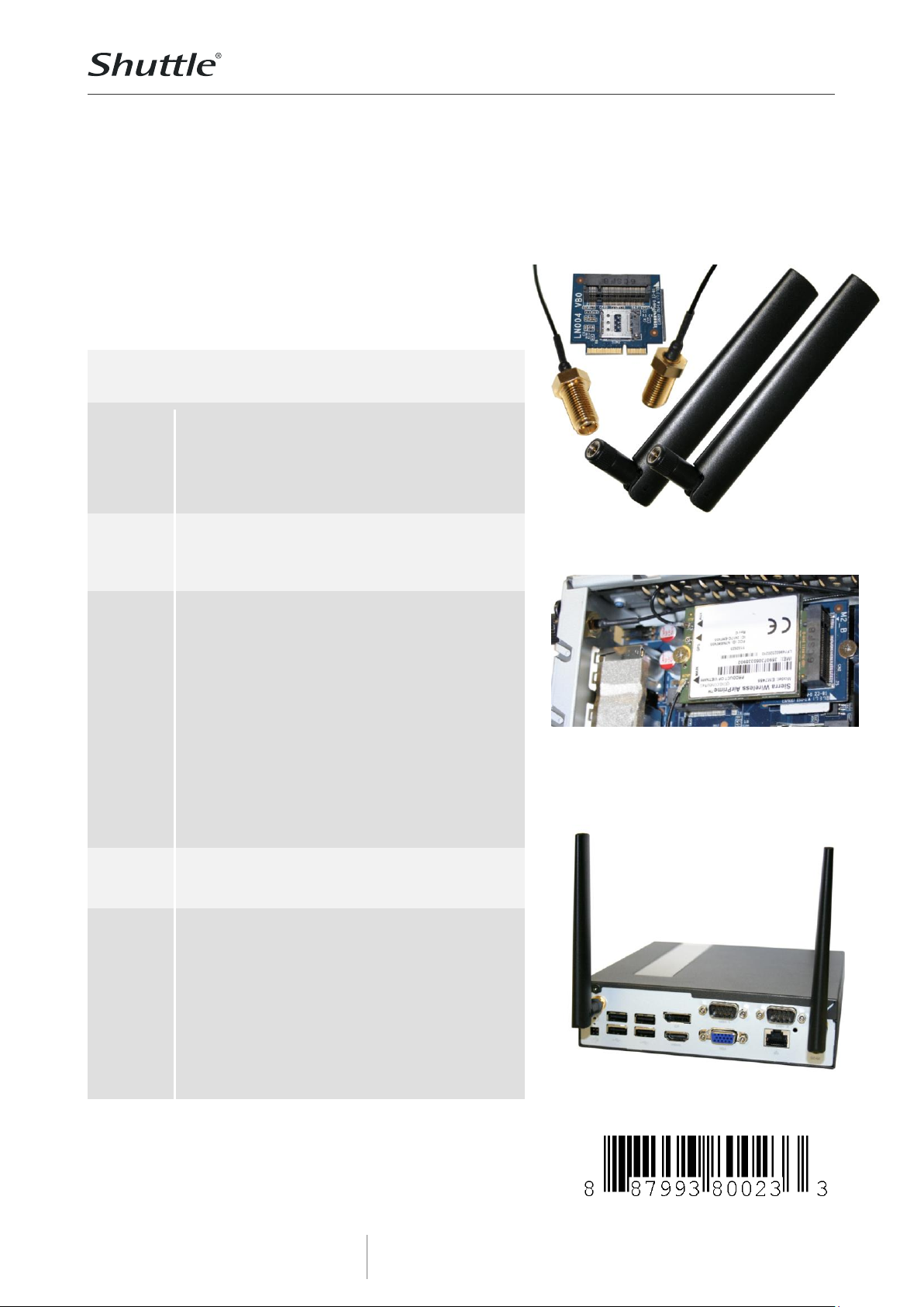
Expansion kit for DL10J
to install a LTE/4G card
If you want integrated mobile network on your Shuttle XPC slim
Barebone DL10J, then you need the Shuttle XPC accessory
WWN01. This kit includes a riser adapter card to support a L TE/4G
module and a Nano SIM card for mobile network. The riser card is
to be install ed into the M.2 -2230 slot and replaces the preinstalled WLAN card. Two antennas with cables ar e als o included
in the delivery.
Feature Highlights
Contents
M.2 adapter card LN004
Fastening scr ew for LTE/4G card (two parts)
2x LTE/4G antennas
2x antenna cables with toothed lock washer
and nut
Quick Installation Guide
Adapter
card
Riser card for the M.2-2230 Key E slot
Dimensions: 30 x 30 mm
supports one LTE/4G module M.2-3042 Key B
supports one S IM card in Nano format
Two external
antennas
LTE/4G dipole omn idirectional antenna
Multi-band: supports EU frequency bands
(800, 1800, 2600 MHz) for GSM/UMTS/LTE and
the following frequency ranges: 704 ~960,
1428~1575, 1720~2170, 2400~2690 MHz
Colour: black
Length overall: 135.7 mm
Dimensions of the antenna body:
114.8 mm x 20.1 mm
Impedance: 50 Ohm
Voltage Standing Wave Ratio (VSWR): <= 3.0
Radiation: Omni
Gain: 2 dBi
Po larisation: vertical
Connector: SMA
Two antenna
cables
RF cable lengths: 20 cm . Connectors:
1. SMA Pigtail female
2. I-PEX MHF 4
Compat ibility
The WWN01 can be used f or
Shuttle XPC slim DL10J
Note that two more comp onents are required for
operation:
LTE/4G module M.2-3042 Key B
SIM card in Nano format
Successfully tested LTE/4G modules:
Sierra EM7455 (CAT 6, for Eu ropa & N-Ame rica)
Sierra EM7430 (CAT 6, for APAC)
Huawei ME906S (CAT 4, for EMEA and other )
Quectel EM06- E (CAT 6, EMEA, Australia, Brazil)
Shuttle XPC accessory
WWN01
Expansion kit for LTE/4G modules
and Nano SIM card
Images for illustration purposes only.
The installed riser card with additional LTE/4G
card (top view) and SIM card (hidden).
The pre-installed WLAN card and WLAN antenna
must be removed before.
DL10J with installed cellular antennas.
Page 2
Product Specifications
w w w . s h u t t l e . e u
Shuttle C o m p u t e r H a n d e l s G m b H
Fr it z- St ras sma nn-S tr . 5
25 337 El msh or n | Ge r ma n y
Te l. +4 9 ( 0 ) 412 1 -4 7 6 8 6 0
Fa x + 4 9 ( 0) 41 21- 47 69 00
sa les @sh ut tle .eu
Page 2 1 5 N ovember 2018
© 2018 by Shuttle Computer Handels GmbH (Germany). All information subject to change without notice
. Pictures for illustration purposes only.
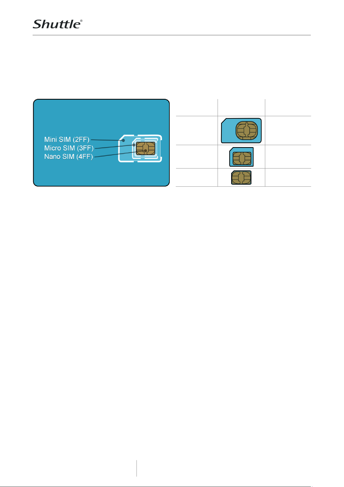
Compatible SIM cards
The SIM card is used to identify your mobile phone in a mobile network. SIM cards have been
shrinked over the years: The Mini standard has been superseded by Micro and Nano. The Shuttle
XPC accessory WWN01 only supports Nano format. A new SIM card usually comes perforated in three
sizes (Mini, Micro and Nano) and simply requires the desired format to be pressed out .
SIM format
Image
Supported by
WWN01?
Mini SIM
25 x 15 mm
No
Micro SIM
15 x 12 mm
No
Nano SIM
12.3 x 8.8 mm
Yes
Page 3

Product Specifications
w w w . s h u t t l e . e u
Shuttle C o m p u t e r H a n d e l s G m b H
Fr it z- St ras sma nn-S tr . 5
25 337 El msh or n | Ge r ma n y
Te l. +4 9 ( 0 ) 412 1 -4 7 6 8 6 0
Fa x + 4 9 ( 0) 41 21- 47 69 00
sa les @sh ut tle .eu
Page 3 1 5 N ovember 2018
© 2018 by Shuttle Computer Handels GmbH (Germany). All information subject to change without notice
. Pictures for illustration purposes only.
Quick Installation Guide for WWN01
Due to safety reasons, please turn off your computer completely first
and unplug it from the power supply.
1. Unfasten two screws on the back panel and
remove the cover.
2. Use a 6mm screwdriver to puncture the
perforated hole on the back panel from the
outside in. Once the screwdriver passes through
the perforation, carefully remove the metal tag.
If the metal tag still does not detach, carefully
bend it by pushing down from the inside of the
chassis.
3. When installing a nano SIM card, please push
the cover to the side and lift it, then carefully
insert the SIM card.
4. Please install the LTE adapter board into the
M.2 E-Key slot interface as shown and affix it by
tightening the screw with bolt firmly.
5. Please apply the bolt and tighten it firmly.
6. Please install the LTE
module in the daughterboard, then tighten the
screw with bolt firmly.
7. Take out the two antenna
cable connectors and
remove the locks and
protective sleeves. Then
connect them to the LTE
module.
Page 4

Product Specifications
w w w . s h u t t l e . e u
Shuttle C o m p u t e r H a n d e l s G m b H
Fr it z- St ras sma nn-S tr . 5
25 337 El msh or n | Ge r ma n y
Te l. +4 9 ( 0 ) 412 1 -4 7 6 8 6 0
Fa x + 4 9 ( 0) 41 21- 47 69 00
sa les @sh ut tle .eu
Page 4 1 5 N ovember 2018
© 2018 by Shuttle Computer Handels GmbH (Germany). All information subject to change without notice
. Pictures for illustration purposes only.
8. Install the antenna cable connectors through the appropriate opening at the back of the chassis.
When leading the cable connector through the opening, check the socket alignment and only push
horizontally. DO NOT turn or twist the cable. Should any difficulties occur, make sure the surface is
clean. Finally, check the alignment again and carefully apply more force.
9. Use the lock to affix the
antenna from the outside.
10. Replace the case cover and fasten its screws.
11. Screw the antennas into
position as pictured. Make sure
they are aligned vertically to
achieve the best possible
signal reception.Make sure the
two antennas are aligned in
the correct direction.
11. Check the following BIOS setting to ensure that the LTE module will be recognized correctly:
Advanced – Onboard Device Configuration – E-Key Device Select = USB
 Loading...