

Page 1
Product Specifications
w w w . s h u t t l e . e u
Shuttle C o m p u t e r H a n d e l s G m b H
Fr it z- St ras sma nn-S tr . 5
25 337 El msh or n | Ge r ma n y
Te l. +4 9 ( 0 ) 412 1 -4 7 6 8 6 0
Fa x + 4 9 ( 0) 41 21- 47 69 00
sa les @sh ut tle .eu
Page 1 2 8 M ay 2020
© 2020 by Shuttle Computer Handels GmbH (Germany). All information subject to change without notice
. Pictures for illustration purposes only.
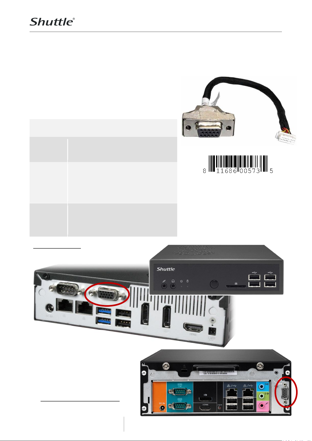
Shuttle Accessory PVG01 –
VGA port expansion kit Shuttle Slim-PCs
The PVG01 adapter equips compatible Shuttle Slim PCs with an
analog VGA output. For the 1L slim PCs this also means only
one serial interface (COM 1) can be used afterwards.
Note: Slim PCs with H81/H110/H310/H410chipset support up to
two displays at the same time so that only t wo out of the
available video outputs can be used.
Feature Highlights
Scope of
delivery
Adapter
Installation guide
Two screws
Specifications
Internal adapter cab le, Cable length:
160 mm
Back panel connector: 15-pin Mini D-
Sub female socket (DE15)
Internal conn ector: Subminiature 2x10 -
pin , 1 mm pitch size, female
Compat ibility
Compat ible to:
1L-Slim-PCs: DX30, DS81, DS87 , DH110,
DH170, DQ170, DH270, DH310, DH370,
DH410, DH410S, DH470
3L-Slim-PCs: XH81(V), XH110(V)
Shuttle XPC Accessory
PVG 01
Images for illustration only.
Shuttle Slim PC DS81
1) Front view
2) Rear view with built-in PVG01 VGA port
Shuttle Slim PC XH81(V) / XH110(V)
Rear view with built-in PVG01 VGA port
Page 2

Product Specifications
w w w . s h u t t l e . e u
Shuttle C o m p u t e r H a n d e l s G m b H
Fr it z- St ras sma nn-S tr . 5
25 337 El msh or n | Ge r ma n y
Te l. +4 9 ( 0 ) 412 1 -4 7 6 8 6 0
Fa x + 4 9 ( 0) 41 21- 47 69 00
sa les @sh ut tle .eu
Page 2 2 8 M ay 2020
© 2020 by Shuttle Computer Handels GmbH (Germany). All information subject to change without notice
. Pictures for illustration purposes only.
Shuttle Accessory PVG01 – Installation Guide
Important Notes:
Please also refer to the installation guide of the
PC before fitting processor, memory and drive.
Required Tools for Installation: Phillips
screwdriver and 5mm hexagon screwdriver (or
flat nose pliers)
Caution: For safety reasons, please ensure
that the power cord is disconnected before
opening the case.
Installation of the adapter:
1. Please remove the case cover, the drive cage
and the processor cooling system as explained
in the installation guide of the PC.
2. Please remove the serial interface on the right
(COM 2) on the back panel of the PC. Undo the
two hexagon screws, remove the D-Sub
connector from its place and also detach its
onboard connector.
3. Please now insert the VGA connector of the
PVG01 adapter in the opening and screw it
tightly.
4. Please connect the other end of the adapter
cable with the appropriate CN25 header on the
mainboard. This connection has a mechanical
reverse polarity protection.
5. Lead the internal cables of the VGA- and COM
port along the sides of the case making sure
these never obstruct the processor cooling
system.
6. If desired, please now install further
components according to the PC's installation
guide. Otherwise please proceed to re-install
the processor cooling, the drive cage and case
cover.
7. Power on the PC and press the "Delete" key on
the keyboard when the message "Press DEL to
run Setup" is prompted. First select the
"Advanced" tab in the BIOS setup screen, then
go to " Onboard Device Configuration", "Serial
Port Configuration" and "Serial Port 2". Here,
you can set the second serial port to "disabled".
To "Save & Exit" the BIOS setup, press F4 on
the keyboard.
 Loading...