

Page 1
Product Specifications
w w w . s h u t t l e . e u
Shu ttle C om pu ter Ha ndel s Gm bH
Fr it z- St ras sma nn -S tr. 5
25337 El ms ho rn | G er ma ny
Te l. + 49 ( 0) 4 12 1- 47 68 6 0
Fa x +4 9 (0 ) 41 21 -4 7 69 00
sa les @sh ut tl e.e u
Page 1 1 M arch 2019
© 2019 by Shuttle Computer Handels GmbH (Germany). All information subject to change without notice
. Pictures for illustration purposes only.
Shuttle Accessory PHD4:
3.5" Hard Disk Rack for 3L slim PC’s
The PHD4 allow s for installation of one 3.5" hard dr ive. However,
doing s o means no other drives such as a slimline DVD drive or a
2.5 " HDD/SSD can be used.
Feature Highlights
Scope of
delivery
3.5 " HDD bracket (1x)
3.5 " HDD power cable (1x)
Screws (4x)
Quick Installation Guide
Compatibility
Compatible wit h the f ollowing Shuttle
Slim-PC Barebone models:
XH81, XH81V, XH97V, X H110, XH110V,
XH170V, XH310, XH310V, XH310R,
XH310RV
Not compatible with XG41, XH61, XH61V
and XH110G
Maximum
ambient
temperature
Caution: Hard disks in Shuttle XPC s lim
PC Barebone s hould o nly be used at
ambient temper atures of up to 40°C.
For higher temperatur es SSDs are
recommended instead.
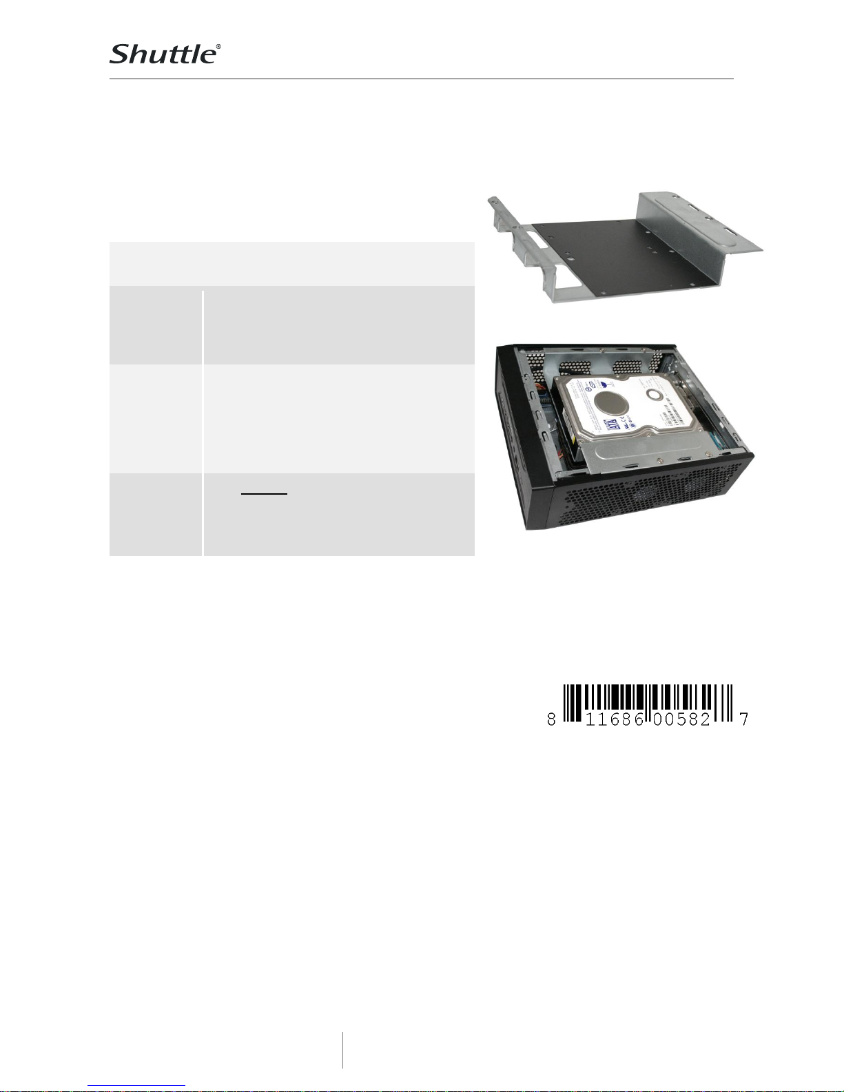
Shuttle Accessory
PHD4
UPC code: 811686005827
Images for illustration only.
Shuttle Slim-PC Barebone (3 litres)
with built-in Accessory PHD4
including 3.5” hard disk drive .
Page 2
Product Specifications
w w w . s h u t t l e . e u
Shu ttle C om pu ter Ha ndel s Gm bH
Fr it z- St ras sma nn -S tr. 5
25337 El ms ho rn | G er ma ny
Te l. + 49 ( 0) 4 12 1- 47 68 6 0
Fa x +4 9 (0 ) 41 21 -4 7 69 00
sa les @sh ut tl e.e u
Page 2 1 M arch 2019
© 2019 by Shuttle Computer Handels GmbH (Germany). All information subject to change without notice
. Pictures for illustration purposes only.
Shuttle Accessory PHD4 – Installation Guide
Important Notes:
The acccessory PHD4 allows for installation of
one 3.5" hard disk in a Shuttle XH81/XH97
barebone PC. Please note that the optical drive
bay will be occupied then.
Due to safety reasons, please turn off your
computer completely first and unplug it from the
power supply.
Please note that no optical drive can be installed,
if a 3.5'' hard disk is used.
Installation of the hard disk rack:
1. Unscrew the two thumbscrews of the chassis
cover. Slide the cover backward and upward.
2. Unplug the SATA and power cables from the
HDD/ODD and remove the racks plus the CPU
thermal module.
Note: Disassembly depending on barebone
model. Please refer to the relevant Quick
Installation Guide when disassembling the
HDD/ODD or CPU cooling.
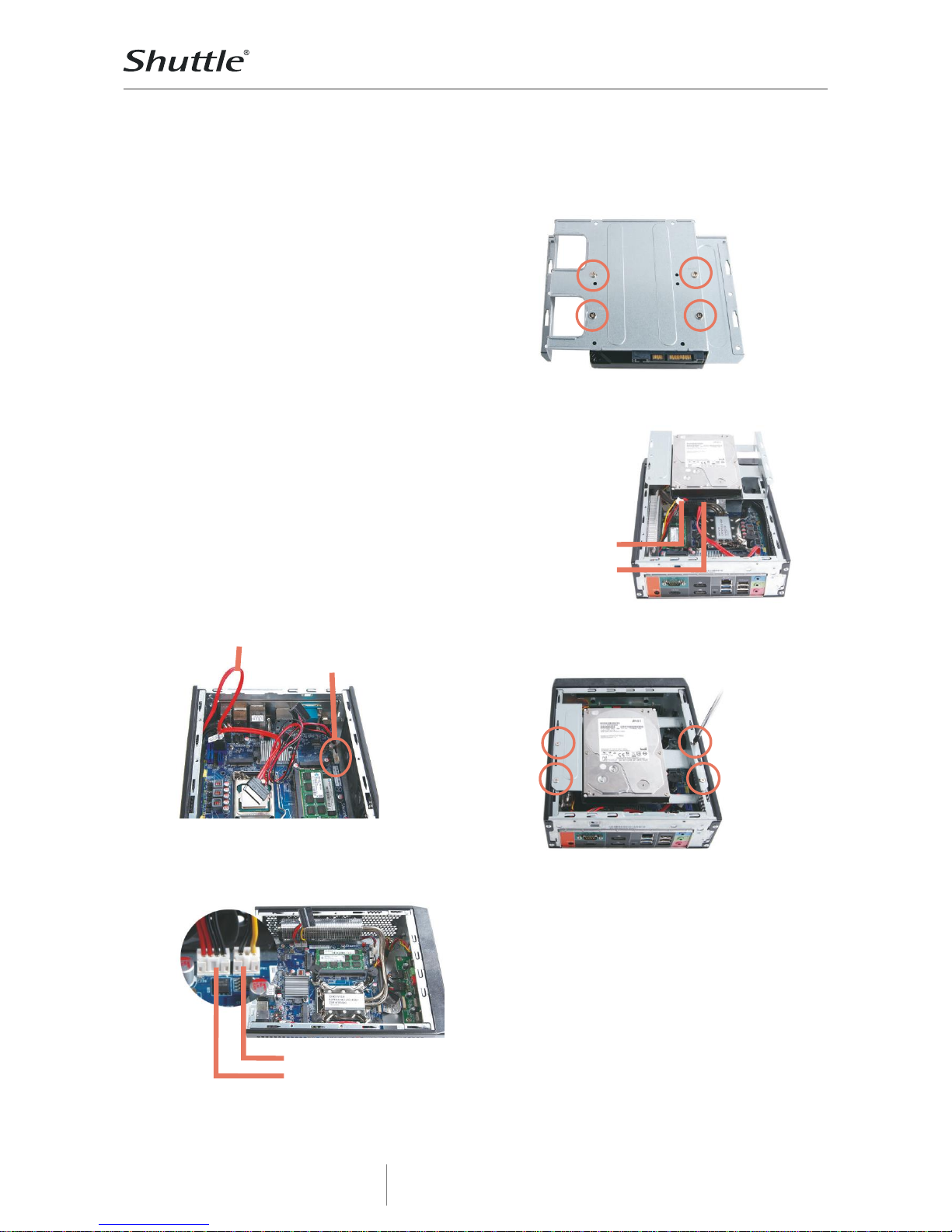
3. Untie all cables and remove the HDD/ODD SATA
power cable from the motherboard as shown in
the picture below.
retain
remove
4. Please connect the 3.5" HDD power connectors
to PW1 (3-pin) and PW2 (4-pin), then proceed to
install the CPU thermal module.
PW1 (12V) 3-pin connector
PW2 (5V) 4-pin connector
Place the 3.5" HDD on the bracket and secure
with four screws.
5. Connect the Serial ATA and power cables to the
3.5" HDD.
SATA power
SATA power
and data
6. Slide the rack back into the chassis and refasten
four screws.
7. Replace the cover and refasten the thumbscrew
 Loading...