

Page 1

MZ11
PPGA Celeron processor
Based AGP MAIN BOARD
User's Manual
- 58 -
Page 2

Shuttle® SpacewalkerTM MZ11
PPGA Celeron® processor based AGPset Mainboard
Manual Version 1.0
Copyright
Copyright© 1999 by Shuttle® Inc. All Rights Reserved.
No part of this publication may be reproduced, transcribed, stored in a retrieval system,
translated into any language, or transmitted in any form or by any means, electronic,
mechanical, magnetic, optical, chemical, photocopying, manual, or otherwise, without
prior written permission from Shuttle® Inc.
Disclaimer
Shuttle® Inc. shall not be liable for any incidental or consequential damages resulting
from the performance or use of this product.
This company makes no representations or warranties regarding the contents of this
manual. Information in this manual has been carefully checked for reliability; however,
no guarantee is given as to the correctness of the contents. In the interest of continued
product improvement, this company reserves the right to revise the manual or include
changes in the specifications of the product described within it at any time without
notice and without obligation to notify any persion of such revision or changes. The
information contained in this manual is provided for general use by the customers.
Trademarks
Spacewalker is a registerred trademark of Shuttle Inc.
Intel, Celeron is a registered trademarks of Intel Corporation.
PC/ATX is a registered trademark of International Business Machines(IBM) Corporation
PS/2 is a registered trademark of IBM Corporation.
AWARD is a registered trademark of Award Software Inc.
Microsoft and Windows are registered trademarks of Microsoft Corporation.
General Notice: Other brand and product names used herein are for identification
purposes only and may be trademarks of their respective owners.
M261
Page 3

Federal Communicationsr Commission (FCC)
Compliance Notice
This equipment has been tested and found to comply with the limits for a Class B digital
device, pursuant to Part 15 of FCC Rules. These limits are designed to provide reasonable protection against harmful interference in a residential installation.
This equipment generates, uses and can radiate radio frequency energy. If not installed and used properly, in strict accordance with the manufacturer's instructions, may
cause harmful interference to radio communications. However, there is no guarantee
that interference will not occur in a particular installation. If this equipment does cause
interference to radio or television reception, which can be determined by turning the
equipment off and on, the user is encouraged to try to correct the interference by one or
more of the following measures :
Reorient or relocate the receiving antenna.
Increase the separation between the equipment and receiver.
Connect the equipment into an outlet on a circuit different from that to which the
receiver is connected.
Consult the dealer or an experienced radio/television technician for help and for
additional suggestions.
The user may find the following booklet prepared by the Federal Communications
Commission helpful "How to Identify and Resolve Radio-TV Interference Problems."
This booklet is available from the U.S. Government Printing Office. Washington, DC
20402, Stock 004-000-00345-4
CE Notice
This device complies with the requirements of the EEC directive 89/336/EEC with
regard to EMC (Electromagnetic Compatibility). Following standards are applied to this
product, in order to achieve compliance with the EMC:
Immunity is in accordance with EN 50082-1 (1992).
Emissions are in accordance with EN 55022 (1987) Class B.
- 2 -
Page 4

T
T
CHAPTER 1 INTRODUCTION .......................................................4
CHAPTER 2 FEATURES ............................................................5
2.1 Specifications ........................................................................................... 5
2.2 Accessories of MB11................................................................................ 7
2.3 Accessories of MZ11 ................................................................................ 8
CHAPTER 3 HARDWARE INSTALLATION ........................................ 9
3.1 The Installation PPGA Celeron Processor................................................. 9
3.2 Jumpers .................................................................................................... 10
3.3 Connectors................................................................................................ 13
CHAPTER 4 MEMORY CONFIGURATION ......................................... 17
CHAPTER 5 FLASH UTILITY ...................................................... 18
TABLE OF CONTENTS
CPU Host Clock and Ratio Selection - JP2, J113 and JP9........................ 10
Clear CMOS - JP11.................................................................................. 11
Keyboard & PS/2 Mouse Power-on Setting - JP1..................................... 11
Wake-On-LAN Setting - JP26.................................................................. 11
On Board Audio Controller Setting - JP25 ............................................... 12
Front Panel Connectors ............................................................................ 13
Back Panel Connectors............................................................................. 14
Other Connectors ..................................................................................... 15
CHAPTER 6 AWARD BIOS SETUP ............................................. 20
The Main Menu .............................................................................................. 21
Standard CMOS Setup.................................................................................... 23
BIOS Features Setup ...................................................................................... 25
Chipset Features Setup ................................................................................... 28
Power Management Setup .............................................................................. 31
PNP/PCI Configuration Setup ........................................................................ 34
CPU Features Setup........................................................................................ 36
Integrated Peripherals ..................................................................................... 38
Password Setting ............................................................................................ 42
- 3 -
Page 5

CHAPTER 7 ONBOARD ATI AGP VGA...................................... 44
General Features............................................................................................. 44
Windows 95/98 Drivers.................................................................................. 45
Windows NT4.0 Driver .................................................................................. 48
CHAPTER 8 ONBOARD CREATIVE 3D AUDIO................................. 51
Introduce ........................................................................................................ 51
General Specification ..................................................................................... 52
Install Creative ES1373 Windows 95/98 Driver ............................................. 53
Install Creative ES1373 Windows NT4.0 Driver ............................................ 56
- 4 -
Page 6

1
1
Congratulations on your purchase of the Shuttle SpacewalkerTM MB11/MZ11
computer mainboard.
The MB11/MZ11 mainboard is a highly integrated IBM PC/ATX compatible
system board designed to meet the industry's most demanding desktop applications.
The MB11 based on the Intel 82443BX AGPset chipset and MZ11 based on the
82443ZX AGPset chipset which both support up to 500MHz PPGA Celeron
processor with MMX technology.
MB11/MZ11 is equipped with an Accelerated Graphics Port (A.G.P.), a highperformance interconnect for graphic-intensive application, such as 3D applications.
The A.G.P. is independent of the PCI bus and is designed to exclusively use with
graphical-display devices. The MB11/MZ11 supports 3.3V A.G.P. devices with
data transfer rates up to 133 MHz, allowing data throughput of 500 MB/sec.
The Intel's 82443BX/82443ZX AGPset chipset provide an integrated Bus Mastering
IDE controller with two high performance IDE interfaces which allows
up to four IDE devices connection and up to 33 MB/sec of data transfer rates.
Onboard Creative ES1373 is an advanced PCI audio controller, it is compatible with
Microsoft Windows, DirectX and Adlib Music Synthesizer, Sound Blaster Pro and
supports thousands of DOS games.
The on-board I/O controller provides standard PC I/O functions:
floppy drive interface, two FIFO serial ports, an InDA device port and a SPP/EPP/
ECP capable parallel port.
MB11 and MZ11 are built with three PCI local bus slots providing a high band-
width data path for data-movement intensive functions such as graphics, and with
one ISA slot.
MB11/MZ11 provides the foundation for cost effective, high performance and
highly expandable platforms, which delivers the latest in the Intel PPGA Celeron
processor and new advanced chipset technology.
INTRODUCTION
- 5 -
Page 7

2
2
FEATURES
The MB11/MZ11 mainboard is carefully designed for the demanding PC user
who wants high performance and maximum intelligent features in a compact
package.
2.1 SpecificationsSpecifications
Chipset:
MB11 : Features Intel's 82443BX AGPset with I/O subsystems.
MZ11 : Features Intel's 82443ZX AGPset with I/O subsystems.
CPU Support:
Intel PPGA Celeron processor 300 ~ 500 MHz.
Versatile Memory Supports:
MB11 : Supports three banks of normal or PC/100 SDRAM
maximum memory size up to 768 MB.
MZ11 : Supports two banks of normal or PC/100 SDRAM
maximum memory size up to 512 MB.
PCI and ISA Expansion Slots:
Provides three 32-bit PCI slots and one 16-bit ISA slot.
Onboard I/O:
Provides a variety of I/O interfaces:
1 x Floppy interface for 3.5-inch FDD or 5.25-inch FDD.
1 x PS/2 mouse connector.
1 x PS/2 Keyboard connector.
2 x DB9 Serial connectors 16C550 UARTS compatible.
1 x Infrared communications port ASKIR and HPSIR compatible.
(Serial port COM2 can also be re-directed to an external IrDA Adapter
for wireless connections.)
1 x DB25 Parallel port supporting Standard Parallel Port and Bi-directional
(SPP), Enhanced Parallel Port (EPP), and Extended Capabilities Port (ECP)
data transmission schemes.
Onboard PCI Bus Master IDE Controller:
Two Ultra DMA/33 Bus Dual-channel Master IDE ports provide support to a
maximum of four IDE devices (one Master and one Slave per channel). The IDE
Bus implements data transfer speeds of up to 33MB/sec IDE and also supports
Enhanced PIO Modes 3 & 4 and Bus Master IDE DMA Mode 2 devices.
- 6 -
Page 8

Onboard Audio Controller:
Provides Creative ES1373 AC97 digital controller, advanced 64 polyphonic wavetable synthesis
with additional DOS support. Full-Duplex Record/Playback at up to 48KHz and supports
Microsoft DirectSound 3D. Digital effects engine for reverb, chorus, tone control.
Onboard AGP VGA Controller:
Provides ATi Rage Pro Chip, support 3D graphics visual and texturing enhancements.
8MB SDRAM on board High-Speed 64-Bit 100MHz Interface.
ATX Power Supply Connector:
ATX power supply unit can connect to the 20-pin ATX power connector onboard, supporting
Suspend and soft-on/off by dual-function power button.
System BIOS:
Provides licensed Award V4.51PG BIOS on 2MB Flash EEPROM.
Supports Green PC, Desktop Management Interface (DMI) and bundled with NCR SCSI BIOS.
ACPI:
Support ACPI (Advanced Configuration and Power Interface) function. ACPI provide more
Energy Saving Features for the future operating system supporting OS Direct Power Management
(OSPM) functionality.
Board Size:
MicroATX form factor, dimension 244mm x 220mm.
Advanced Features:
Low EMI -- Using built-in Spread Spectrum with 1.5% modulation and automatic clock shutoff of unused PCI/SDRAMS slots to reduce the Electromagnetic Interference (EMI).
Dual Function Power Button -- The system can be one of two states, one is Suspend mode and
the other is the Soft-off mode. Pushing the power button for less than 4 seconds will place the
system into Suspend mode. When push the power button for more than 4 seconds, the system
enters the Soft-off mode.
Wake-On-LAN -- The Wake-On-LAN connector onboard can be attached to a network card
that supports this function to wake up the system via the LAN.
(This function support Intel LAN card only).
Modem Ring Power-on -- The system can be powered on automatically by activation of
modem ring.
PS/2 Keyboard & Mouse Power-on -- The system will power-on automatically by stroke
keyboard or double click PS/2 mouse.
Optional Features:
Voltages Monitoring -- Various voltages of key elements, such as the CPU, and other critical
system voltage levels are monitored to ensure stable current reach to mainboard components.
System voltages include VCORE/VL2 on CPU, and +5V, +12V, -5V, -12V on system.
FAN Status Monitoring -- To prevent CPU overheat, CPU fans is monitored for RPM and
failure. (CPU Cooling FAN with RPM sensor is required)
- 7 -
Page 9

2.2 Accessories Of MB11Accessories Of MB11
- 8 -
Page 10

2.3 Accessories Of MZ11Accessories Of MZ11
- 9 -
Page 11

3
3
HARDWARE INSTALLATION
3.1 The Installation PPGA Celeron ProcessorThe Installation PPGA Celeron Processor
MB11/MZ11 mainboard provides a 370-pin ZIF Socket370 for Intel PPGA Celeron CPU.
The CPU that came with the mainboard should have a fan attached to it to prevent overheating. If this is not the case then purchase a fan before you turn on your system.
To install a CPU, first turn off your system and remove its cover. Locate the ZIF
Socket370 and open it by first pulling the lever sideways away from the socket then
upwards to a 90-degree right angle. Insert the CPU with the correct orientation as
shown.(Figure 3-1) Use the notched corner of the CPU as your guide. The notched corner
should point towards the end of the lever. Notice that there are two blank area where one
hole is missing from that corner of the square array of pin holes. Because the CPU has a
corner pin for two of the four corner, the CPU will only fit in the one orientation, hold
down on the CPU and close the socket’s lever.
Figure 3-1
Then you should have a CPU fan that will
cover the face of the CPU. Apply thermal
jelly to the CPU metallic top and then
install the fan onto the CPU. (Figure 3-2 )
- 10 -
Figure 3-2
Page 12

3.2 JumpersJumpers
Several hardware settings are made through the use of jumper caps to connect jumper pins
on the main board. The jumper's pin 1 on main board will be on the top or on the left
when holding the main board with the keyboard connector away from yourself.
Jumpers with two pins will be shown as for Close (On) and for Open (Off).
To connect the pins, simply place a plastic jumper cap over the two pins.
CPU Host Clock and Ratio Selection - JP2 and JP14
MB11/MZ11 mainboard features a clock generator to provide adjustable system clock
frequency. Jumper JP2 determine the system clock frequency 66MHz to 100MHz. JP14
is a 15-pin jumper which determine the processor clock ratio from 3X to 8X.
Figure 3-3 shows the position of JP2
and JP14 on the mainboard.
Table 3-1 shows adjustable System
clock on jumper JP2.
Table 3-2 shows adjustable CPU
Clock Ratio on jumper group JP14.
Note: Present PPGA Celeron CPU Clock
Ratio is fixed and unable to adjust,
for those processors, JP14 is not
functional.
Figure 3-3
CPU
Host Cl ock
66 M Hz
75 M Hz
83 M Hz
100 MHz
103 MHz
Table 3-1
JP2
CPU
Clock Ratio
3 x
3.5 x
( 350 / 100 )
4 x
( 400 / 100 )
4.5 x
( 300 / 66 )
( 450 / 100 )
5 x
( 333 / 66 )
( 500 / 100 )
5.5 x
( 366 / 66 )
- 11 -
JP14
CPU
Clock Ratio
6 x
( 400 / 66 )
6.5 x
( 433 / 66 )
7 x
( 466 / 66 )
7.5 x
( 500 / 66 )
8 x
JP14
Table 3-2
Page 13

Clear CMOS - JP11
MB11/MZ11 mainboard supports jumper JP11 for
discharging mainboard's CMOS memory.
This jumper can clear the CMOS data stored in
the I/O chip. To clear the CMOS data please
follow listed steps:
1) Turn off the PC,
2) Remove mini jumper from JP11 pin 1-2,
3) Insert mini jumper to JP11 pin 2-3 for a
brief while,
4) Remove mini jumper from JP11 in 2-3,
5) Reinsert mini jumper to JP11 pin 1-2,
6) Turn on the PC.
Figure 3-4
K/B & PS/2 Mouse Power-On Setting - JP1
MB11/MZ11 mainboard provides an optional power-on
function by stroke any key (or hot-key) on keyboard
or double click on PS/2 mouse.
Note: Power-on by serial mouse is not supported
JP1 is the jumper used to set the functions of keyboard
& PS/2 mouse power-on Enabled or Disabled.
When you enabled K/B & PS/2 Mouse Power-ON
function, you also have to set the proper item on
POWER ON function category of Integrated
Peripherals of BIOS setup.
Wake-On-LAN Setting - JP26
JP26 Close (On)
Wake-On-LAN Function Enabled
JP26 Open (Off)
Wake-On-LAN Function Disabled
K/B & PS/2 Mouse Power-On JP1
Keyboard &
PS/2 Mouse
Power-On
Disabled
PS/2 Mouse
Power-On
Enabled
Keyboard &
PS/2 Mouse
Power-On
Enabled
Keyboard
Power-On
Enabled
Table 3-3
- 12 -
Figure 3-5
Page 14

On Board Audio Controller Setting - JP25
MB11/MZ11 mainboard provides on-board PnP
64 voices wavetable sound chip which based
on Creative ES1373 PnP 3D integrated audio
controller chip.
Jumper JP25 is used to enable or disable it.
JP25 Pin 2-3 Close (On)
On-board Audio Controller Enabled (default)
JP25 Pin 1-2 Close (On)
On-board Audio Controller Disabled
Figure 3-6
- 13 -
Page 15

3.3 ConnectorsConnectors
Front Panel Connectors (J18)
PW-LED Connector - PWR-LED
Attach 3-pin Power-LED connector cable from the housing front panel to PWR-LED
header on the mainboard. The power LED stays lights while the system is running.
Speaker Connector - SPK
Attach the PC speaker cable from the case to the 4-pin speaker connector (SPK).
Hardware Reset Connector - RST
Attach the 2-pin hardware reset switch cable to RST header. Closing the reset switch causes the
system to restart.
HDD LED Connector - IDE LED
Attach the connector cable from the IDE device LED to the 2-pin IDE LED header. The
HDD LED lights up whenever an IDE device is active.
Green LED Connector - GRN LED
Attach a 2-pin Green LED cable to it. The Green LED lights when the system get into
power saving mode. The Green LED off when the system resume back to normal mode.
EPMI Connector - SMI
Hardware System Management Interface connector may attach a 2-pin momentary switch
to it. When push it will force system get into power saving mode, and the system will
resume when switch is pushed again.
ATX Power On/Off Switch Connector - PWR-SW
Attach a 2-pin momentary type switch to this connector for turning on or off your ATX
power supply.
- 14 -
Figure 3-7
Page 16

Back Panel Connectors
Locate the back panel connectors to attach all your external peripherals, such as parallel
printer, VGA, Line-Out, Line-In, Mic-In, Game/MIDI, PS/2 mouse, PS/2 keyboard, and USB
devices. Plug the signal cable from each peripheral device directly into the corresponding
connector at the back panel of the mainboard, as explained below:
Figure 3-8
PS/2 Keyboard & PS/2 Mouse Connector
Two 6-pin female PS/2 keyboard & Mouse connectors are located at the rear panel of the main
board. Depending on the computer housing you use (desktop or minitower), the PS/2 Mouse
connector is situated at the top of the PS/2 Keyboard connector when the mainboard is laid
into a desktop, as opposed to a mini-tower where the PS/2 Mouse connector is located at the
right of the PS/2 Keyboard's. Plug the PS/2 keyboard and mouse jacks into their corresponding connectors.
USB1/USB2 Port Connectors
Two female connectors USB1/USB2 share the same USB (Universal Serial Bus) bracket at the
rear panel of your mainboard. Plug each USB device jack into an available USB1/USB2
connector.
COM1 Connectors
This mainboard can accommodate up to one serial device on COM1. Attach each serial
device cable to the DB9 serial port COM1 at the back panel of your computer.
Parallel Port Connector
One DB25 female parallel connector is located at the rear panel of the mainboard. Plug the
connection cable from your parallel device (printer, scanner, etc.) into this connector.
VGA Connector
Attach 15-pin VGA cable to this connector.
Game/MIDI Connector
The Game/MIDI port is a 15-pin female connector, please refer to "CHARTER 6 ON BOARD
SOUND CHIP SETTING" "Connecting Audio Devices to MB11/MZ11".
Line-Out/Line-In/Mic-In Connectors
The Line-Out/Line-In/Mic-In ports are 1/8-inch connectors, please refer to "CHARTER 6 ON
BOARD SOUND CHIP SETTING" "Connecting Audio Devices to MB11/MZ11".
- 15 -
Page 17

Other Connectors
ATX Power Supply Connector - J2
It is a 20-pin male header connector is connected
to the ATX power supply. The plug of the power
supply will only insert in one orientation because of
the different hole shade and size. Find the proper
orientation and push down firmly making sure that
the pins are aligned.
Figure 3-9 shows ATX Power Supply Connector.
IR Connector - J16
If you have an Infrared device, this mainboard can
implement IR (Infrared) transfer and meet both
ASKIR and HPSIR specifications. To enable the
IR transfer function, follow these steps:
Step 1. Attach the 5-pin infrared device cable to
J16 connector. (Refer to the above diagram
for IR pin assignment.)
Step 2. Configure the Infrared transfer mode in the
UR2 Mode field of Integrated Peripherals
menu in BIOS Setup. This mainboard
supports IrDA 1.0, ASKIR, MIR 0.57M
and MIR 1.15M transfer modes. FIR is
not currently supported.
Enhanced IDE, Floppy and COM2
Connectors
The mainboard shipped with one 40-pin ribbon cable
for IDE H.D.D, one 34-pin ribbon cable for F.D.D.
and one 10-pin ribbon cable for COM2. Flat cables
should be connected with the red stripe on the pin 1
side of the connector.
Figure 3-9
Figure 3-10
Figure 3-12
- 16 -
Figure 3-11
Page 18

CPU, System & AGP cooling Fan
Connectors - FAN1, FAN2 & FAN3
The main board provides three onboard 12V cooling
fan power connectors. Depending on the fan maker,
the wiring and plug may be different. The red wire
should be connected to +12V and black wire should
be connected to ground (GND).
Wake-On-LAN Connector - J19
Attach a 3-pin connector from the LAN card which
supports the Wake-On-LAN (WOL) function. This
function lets users wake up the connected system
through the LAN card.
SB-Link Connector - SB-LINK
The main board provides a 2x3 pin SB-Link header
accepts the Creative CT4600 series PCI sound cards
with PCI solution to connect the legacy Sound Blaster
compatible audio to the PCI bus.
CD Audio Connectors - J15 and J14
CD-IN
Port J15 and J14 (2,4,6,8-pin) are used to attach
CD-ROM audio connector.
J15 (CD_IN) pin assignment :
4 = Left Channel
3 = Ground
2 = Right Channel
1 = Ground
J14 (CD_IN) pin assignment :
8 = Right Channel
6 = Ground
4 = Ground
2 = Left Channel
TAD
Port J14 (1,3,5,7-pin) can be used to connect a
modem audio line to MB11/MZ11. You would use
this connector when telephone answering
machine software for input and
output.
J17 (TAD) pin assignment :
7 = PHONE
5 = Ground
3 = Ground
1 = MONO
Figure 3-13
Figure 3-14
- 17 -
Page 19

4
MEMORY CONFIGURATION4
The MB11/MZ11 mainboard provides three/two 168-pin DIMM sockets that
make it possible to install from 8MB up to 768/512MB of SDRAM. The DIMM
socket support 8MB, 16MB, 32MB, 64MB, 128MB and 256MB 3.3V single- or
double- side SDRAM DIMM.
The DIMM sockets are arranged in all banks of one socket each. Each bank
provides a 64/72-bit wide data path.
MB11/MZ11 provides data integrity features including ECC (Error Checking and
correcting) in the memory array. ECC mode provides single and multiple bit error
detection.
Install memory in any or all of the banks in any combination as follows:
Mode
MB11
MZ11
DIMM
Socket
DIM1
DIM2
DIM3
DIM1
DIM2
Memory Modules
8MB, 16MB, 32MB, 64MB, 128MB, 256MB
168-pin 3.3V SDRAM DIMM
8MB, 16MB, 32MB, 64MB, 128MB, 256MB
168-pin 3.3V SDRAM DIMM
8MB, 16MB, 32MB, 64MB, 128MB, 256MB
168-pin 3.3V SDRAM DIMM
8MB, 16MB, 32MB, 64MB, 128MB, 256MB
168-pin 3.3V SDRAM DIMM
8MB, 16MB, 32MB, 64MB, 128MB, 256MB
168-pin 3.3V SDRAM DIMM
Mudule
Quantity
x 1
x 1
x 1
x 1
x 1
Table 4-1
Figure 4-1 : MB11/MZ11 provides three DIMM
sockets
Figure 4-2 : provides two DIMM sockets
- 18 -
Page 20

5
5
This chapter briefly discusses Award Flash utility in order to guide you through
updating your old BIOS. The file name we use to program here is test.bin, and the
file name to save old BIOS is MX11.OLD. Please note that those file names are
not absolute. They are only examples to let you have a more clear understanding of
the updating process.
How to Begin
1. Please type “awdflash” and press the ENTER key to begin the updating
2. Once you enter, you will see a main menu displaying:
3. Move the cursor to “File Name to Program: ”
4. Type the program name “test.bin”, and then press the ENTER key.
5. At the bottom of the menu, you will be requested to answer:
FLASH UTILITY
process.
“Do You Want to Save BIOS (Y/N)? ”
The following manual is intended to guide you through the process of both “No”
and “Yes” cases respectively.
If “No”
If you do not wish to save the old BIOS:
1. Please type “N”, and then press the ENTER key.
2. Then you will be requested to answer:
“Are You Sure to Program? “
3. Answer “N” if you do not want to program, and then it will exit.
- 19 -
Page 21

If “Yes”
To save the old BIOS:
1. Please respond “Y”, and then press the ENTER key.
2. Move the cursor to “File Name to Save: “
3. Type file name “TEST.BIN”, and then press the ENTER key. (Your old BIOS
will be saved in the file name you create. In this case, the old BIOS is saved
in the file name, MX11.OLD).
4. Then you will be requested to answer:
“Are You Sure to Program (Y/N)? “
5. Type “Y” to begin programming, and press the ENTER key.
6. When the programming is finished, the showing message will appear:
7. Once you see the showing message “Power Off or Reset System”,
please restart your system.
8. When you power on the computer again, you will find your old BIOS has
already been successfully updated.
To view a complete usage of FLASH utility, please type “awdflash /?” and
press the ENTER key.
Notes About Award Flash Utility
Please note that Award Flash Utility cannot run under EMM386 or QEMM.
Thus, when executing the command “awdflash”, an error message will appear:
“Error Message: Fail — Due to EMM386 or QEMM !”
- 20 -
Page 22

6
6
The BIOS ROM has a built-in Setup program that allows users to modify the basic
system configuration. This type of information is stored in battery-backed RAM so
that it retains the Setup information when the power is turned off.
Entering Setup
Power on the computer and press <Del> immediately will allow you to enter Setup.
The other way to enter Setup is to power on the computer, when the below message
appear briefly at the bottom of the screen during the POST (Power On Self Test),
press <Del> key or simultaneously press <Ctrl>,<Alt>, and <Esc> keys.
“Press DEL to enter SETUP”
If the message disappears before you respond and you still wish to enter Setup,
restart the system to try again by turning it OFF the ON or pressing the “RESET”
button on the system case. You may also restart by simultaneously press <Ctrl>,
<Alt>, and <Delete> keys. If you do not press the keys at the correct time and the
system does not boot, an error message will be displayed and you will again be
asked to,
“Press F1 to Continue, DEL To Enter Setup”
BIOS SETUP
- 21 -
Page 23

6.1 The Main MenuThe Main Menu
Standard CMOS Setup
This setup page includes all items in a standard compatible BIOS.
BIOS Features Setup
This setup page includes all items of Award special enhanced features.
Chipset Features Setup
This setup page includes all items of chipset features.
Power Management Setup
This setup page includes all items of Power Management features.
PNP/PCI Configuration Setup
This item specifies the value (in units of PCI bus blocks) of the latency timer for the
PCI bus master and the IRQ level for PCI device. Power-on with BIOS defaults
Load BIOS Defaults
BIOS defaults loads the values required by the System for the maximum performance.
However, you can change the parameter through each Setup Menu.
Load Setup Defaults
Setup defaults loads the values required by the system for the O.K. performance.
However, you can change the parameter through each Setup Menu.
- 22 -
Page 24

CPU Speed Setting
This setup includes all items of CPU speed features.
Integrated Peripherals
This setup page includes all items of peripheral features.
Supervisor Password
Change, set, or disable supervisor password. It allows you to limit access to the
system and Setup, or just to Setup.
User Password
Change, set, or disable user password. It allows you to limit access to the system and
Setup, or just to Setup.
IDE HDD Auto Detection
Automatically configure IDE hard disk drive parameters.
Save & Exit Setup
Save CMOS value change to CMOS and exit setup
Exit Without Saving
Abandon all CMOS value changes and exit setup.
- 23 -
Page 25

6.2 Standard CMOS SetupStandard CMOS Setup
Date
The date format is <day>, <month> <date> <year>. Press <F3> to show the calendar.
Time
The time format is <hour> <minute> <second>. The time is calculated base on the
24-hour military-time clock. For example. 5 p.m. is 17:00:00.
Hard Disks Type
This item identify the types of hard disk drives that has been installed in the computer. There are 46 predefined types and a user definable type.
Press PgUp or PgDn to select a numbered hard disk type or type the number and press
<Enter>. Note that the specifications of your drive must match with the drive table.
The hard disk will not work properly if you enter improper information for this item.
If your hard disk drive type is not matched or listed, you can use Type User to define
your own drive type manually.
If you select Type User, related information is asked to be entered to the following
items. Enter the information directly from the keyboard and press <Enter>. Those
information should be provided in the documentation from your hard disk vendor or
the system manufacturer.
The user may also set those items to AUTO to auto configure hard disk drives parameter when system power-on.
If a hard disk drive has not been installed select NONE and press <Enter>.
- 24 -
Page 26

Drive A type / Drive B type
This item specifies the types of floppy disk drive A or drive B that has been installed
in the system.
Video
This item selects the type of adapter used for the primary system monitor that must
matches your video display card and monitor. Although secondary monitors are
supported, you do not have to select the type in Setup.
Halt On
This item determines if the system will stop, when an error is detected during power
up.
Memory
This item is display-only. It is automatically detected by POST (Power On Self Test)
of the BIOS.
Base Memory
The POST of the BIOS will determine the amount of base (or conventional)
memory installed in the system. The value of the base memory is typically 512K
for systems with 512K memory installed on the mainboard, or 640K for systems
with 640K or more memory installed on the mainboard.
Extended Memory
The BIOS determines how much extended memory is present during the POST.
This is the amount of memory located above 1MB in the CPU's memory address
map.
- 25 -
Page 27

6.3 BIOS Features SetupBIOS Features Setup
Virus Warning
When this item is enabled, the Award BIOS will monitor the boot sector and partition
table of the hard disk drive for any attempt at modification. If an attempt it made, the
BIOS will halt the system and the following error message will appear. Afterwards,
if necessary, you will be able to run an anti-virus program to locate and remove the
problem before any damage is done.
Disk boot sector is to be modified
Type "Y" to accept write or "N" to abort write
!WARNING!
Award Software, Inc.
CPU Internal Cache
This item enables CPU internal cache to speed up memory access.
External Cache
This item enables CPU secondary cache to speed up memory access.
CPU L2 Cache ECC Checking
When you select Enabled, memory checking is enable when the external cache
contains ECC SRAMs.
Quick Power On Self Test
This item speeds up Power On Self Test (POST) after you power on the computer.
If it is set to Enabled, BIOS will shorten or skip some check items during POST.
- 26 -
Page 28

Boot Sequence
This item determines which drive computer searches first for the disk operating
system. Default setting is A, C, SCSI.
BIOS also support system boot from CD-ROM drive or SCSI hard disk drive.
Swap Floppy Drive
When this item enables, the BIOS will swap floppy drive assignments so that Drive
A: will function as Drive B: and Drive B: as Drive A:.
Boot Up Floppy Seek
When this item enables, the BIOS will swap floppy drive assignments so that Drive
A: will function as Drive B: and Drive B: as Drive A:.
Boot Up NumLock Status
When this option enables, BIOS turns on Num Lock when system is powered on.
Gate A20 Option
This entry allows you to select how the gate A20 is handled. The gate A20 is a
device used to address memory above 1 MByte. Initially, the gate A20 was handled
via a pin on the keyboard. Today, while keyboards still provide this support, it is
more common, and much faster, set to Fast for the system chipset to provide support
for gate A20.
Typematic Rate Setting
This determines if the typematic rate is to be used. when disabled, continually holding
down a key on your keyboard will generate only one instance. In other words, the
BIOS will only report that the key is down. When the typematic rate is enabled, the
BIOS will report as before, but it will then wait a moment, and, if the key is still
down, it will begin the report that the key has been depressed repeatedly. For example, you would use such a feature to accelerate cursor movements with the arrow
keys.
Typematic Rate (Chars/Sec)
When the typematic rate is enabled, this selection allows you select the rate at which
the keys are accelerated.
Typematic Delay (Msec)
When the typematic rate is enabled, this selection allows you to select the delay
between when the key was first depressed and when the acceleration begins
Security Option
This item allows you to limit access to the System and Setup, or just to Setup.
When System is selected, the System will not boot and access to Setup will be denied
if the correct password is not entered at the prompt.
When Setup is selected, the System will boot, but access to Setup will be denied if
the correct password is not entered at the prompt.
- 27 -
Page 29

PCI/VGA Palette Snoop
This item must be set to enabled if there is a MPEG ISA card installed in the system,
and disabled if there is no MPEG ISA card installed in the system.
OS Select For DRAM > 64MB
This item allows you to access the memory that over 64 MB in OS/2.
Report No FDD For WIN 95
This item enable for report No FDD for WIN95 if No FDD install.
Video BIOS Shadow
Determines whether video BIOS will be copied to RAM. However, it is optional
depending on chipset design. Video Shadow will increase the video speed.
C8000-CBFFF Shadow / DC000-DFFFF Shadow
These categories determine whether option ROMs will be copied to RAM. An
example of such option ROM would be support of SCSI Add-on card.
- 28 -
Page 30
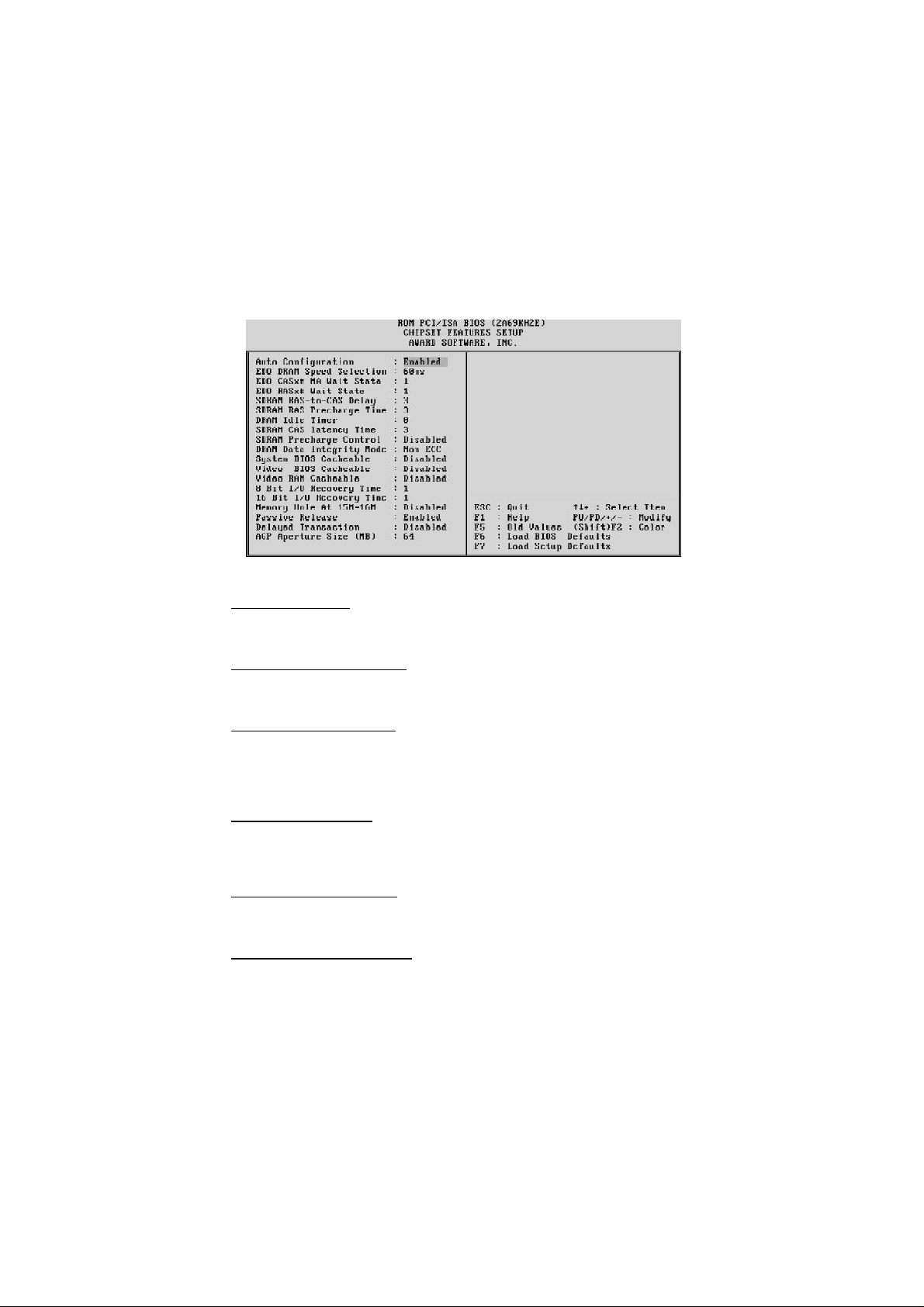
6.4 Chipset Features SetupChipset Features Setup
Auto Configuration
The default setting of the optimal timings for items 3 through 7 for 60ns EDO DRAM
modules.
EDO DRAM Speed Selection
This item set the EDO DRAM Read/Write timings that the system uses. When item
of "Auto Configuration" is disabled, this item will not show up.
EDO CASx# MA Wait State
The board designer may elect to insert one additional wait state before the assertion
of the first CASx# for page hit cycles, thus allowing one additional clock of MA
setup time to the CASx# for the leadoff page hit cycle. Do not change from the
manufacturer's default unless you are getting memory addressing errors.
EDO RASx# Wait State
The board designer may elect to insert one additional wait state before RASx# is
asserted for row misses, thus allowing one additional MAX [13:0] setup time to
RASx# assertion. This field applies only if EDO DRAM is installed in the system.
SDRAM RAS-to-CAS Delay
This field lets you control the number of DCLKs between a Row Activate command
and a read or write command.
SDRAM RAS Precharge Time
The precharge time is the number of cycles it takes for the RAS to accumulate its
charge before DRAM refresh. If insufficient time is allowed, refresh may be incomplete and the DRAM may fail to retain data. This field applies only if synchronous
DRAM is installed in the system.
- 29 -
Page 31

DRAM Idle Timer
This item specifies the number of clocks that the DRAM controller will remain id
IDLE state before precharging all pages.
SDRAM CAS Latency Time
When synchronous DRAM is installed, you can control the number of CLKs between
when the SDRAMs sample a read command and when the controller samples read
data from the SDRAMs. Do not reset this field from the default value specified by the
system designer.
SDRAM Precharge Control
When Enabled, all CPU cycles to SDRAM result in and All Banks Precharge Command on the SDRAM interface.
DRAM Data Integrity Mode
This item allows the user to set DRAM data integrity mode to Non-ECC or ECC.
Non-ECC has byte-wide write capability but no provision for protecting data integrity
in the DRAM array. ECC allows a detection of single-bit and multiple-bit errors and
recovery of single-bit errors.
System BIOS Cacheable
This item allows the user to set whether the system BIOS F000 ~ FFFF areas are
cacheable or non-cacheable.
Video BIOS Cacheable
This item allows the user to set whether the video BIOS C000 ~ C7FF areas are
cacheable or non-cacheable.
Video RAM Cacheable
This is a new cache technology for the video memory of the processor. It can greatly
improve the display speed by caching the display data. You must leave this on the
default setting of Disabled if your display card cannot support this feature or else your
system may not boot.
8 Bit I/O Recovery Time
The recovery time is the length of time, measured in CPU clocks, which the system
will delay after the completion of an input/output request. This delay takes place
because the CPU is operating so much after than the input/output bus that the CPU
must be delayed to allow for the completion of the I/O.
This item allows you to determine the recovery time allowed for 8 bit I/O. Choices
are from NA, 1 to 8 CPU clocks.
16-Bit I/O Recovery Time
This item allows you to determine the recovery time allowed for 16 bit I/O. Choices
are from NA, 1 to 4 CPU clocks.
- 30 -
Page 32

Memory Hole At 15M-16M
In order to improve performance, certain space in memory can be reserved for ISA
cards. This memory must be mapped into the memory space below 16 MB.
Passive Release
When enabled, the chipset provides a programmable passive release mechanism to
meet the required ISA master latencies.
Delayed Transaction
Since the 2.1 revision of the PCI specification requires much tighter controls on
target and master latency. PCI cycles to or from ISA typically take longer. When
enabled, the chipset provides a programmable delayed completion mechanism to
meet the required target latencies.
AGP Aperture Size (MB)
This item allows the user to set memory-mapped, graphics data structures can reside
in Graphics Aperture.
- 31 -
Page 33

6.5 Power Management SetupPower Management Setup
Power Management
This item determines the options of the power management function. Max Saving
puts the system into power saving mode after a brief period of system inactivity; Min
Saving is the same as Max Saving except the time of the system inactivity period is
longer; Disabled disables the power saving feature; User Defined allows you to set
power saving options according to your preference.
PM Control by APM
If this item set to No, system BIOS will be ignored and APM calls the power to
manage the system.
If this item setup to Yes, system BIOS will wait for APM's prompt before it enter any
PM mode e.g. DOZE, STANDBY or SUSPEND.
Video Off Method
This item define the video off features -V/H SYNC + Blank, DPMS, and Blank Only.
The first option, which is the default setting, blanks the screen and turns off vertical
and horizontal scanning; DPMS allows the BIOS to control the video display card if
it supports the DPMS feature; Blank Screen only blanks the screen.
Video Off After
This item define when to activate the video off feature for monitor power management. The settings are N/A, Doze, Standby and Suspend.
MODEM Use IRQ
This item determines the IRQ in which the MODEM can use.
The choice: 1, 3, 4, 5, 7, 9, 10, 11, N/A.
- 32 -
Page 34

Doze Mode
When enabled and after the set time of system inactivity, the CPU clock will run at
slower speed while all other devices still operate at full speed.
Standby Mode
When enabled and after the set time of system inactivity, the fixed disk drive and the
video would be shut off while all other devices still operate at full speed.
Suspend Mode
When enabled and after the set time of system inactivity, all devices except the CPU
will be shut off.
HDD Power Down
This item defines the continuous HDD idle time before the HDD enters power saving
mode (motor off). The options are from 1 min to 15 min and Disabled.
Throttle Duty Cycle
This item determines the duty cycle for the clock control thermal throttling mode.
The duty cycle indicates the percentage of time while in the thermal throttle mode.
The settings between 12.5% and 87.5%.
PCI/VGA Act-Monitor
If this item is set to Enabled, the VGA activity event will be monitored to reload
global timer.
Soft-Off by PWR-BTTN
The setting of Instant-Off allows the ATX switch to function as a normal system
power off button when pressed for less than 4 seconds. The setting of Delay 4 Sec.
allows the button to have a dual function where to press the button for less than 4
seconds will place the system in suspend mode, and pressing the button for more
than 4 seconds will shut place the system off.
CPUFAN OFF In Suspend
This item determineCPU fan status when the system enters suspend mode.
The options Enabled and Disabled.
PowerOn by Ring
This item determine the system will resume by activating of modem ring.
Power On on PCI card
This item determine the system will power-on by activity of PCI card which with
"PME" signal.
Resume by Alarm
This item determine the system will resume by activity of R.T.C. If enabled this
feature and enter resume date and time. When date and time expire, system will
power-on itself from power off.
- 33 -
Page 35

IRQ 8 Break Suspend
You can turn On or Off monitoring of IRQ8 (the Real Time Clock) so it does not
awaken the system from Suspend mode.
** Reload Global Timer Events **
If any of these items is set to Disabled, that system activity event will not be monitored to reload global timer.
If these items is set to Enabled, that system activity event will be monitored to reload
global timer.
These items include IRQ[3-7, 9-15], NMI, Primary IDE0/1, Secondary IDE 0/1,
Floppy Disk, Serial Port and Parallel Port.
Resume by LAN (Wake-ON-LAN)
This item determine the system will resume by activity of LAN. If enabled this
feature system will power-on itself from power off when the activity of LAN.
Note : MB11/MZ11 support Wake-ON-LAN function with Intel LAN card only.
- 34 -
Page 36

6.6 PNP/PCI Configuration SetupPNP/PCI Configuration Setup
PNP OS Installed
When this item is set to Yes, it will allow the PnP OS(Windows 95) control the
system resources except PCI devices and PnP boot devices.
Default setting is No.
Resources Controlled By
The Award Plug and Play BIOS has the capability to automatically configure all of
the boot and Plug and Play compatible devices. However, this capability means
absolutely nothing unless you are using a Plug and Play operating system as Windows 95.
Reset Configuration Data
This item allows you to determine whether to reset the configuration data or not.
IRQ 3/4/5/7/9/10/11/12/14/15, assigned to
These items allow you to determine the IRQ assigned to the ISA bus and is not
available for PCI slot. Choices are Legarcy ISA and PCI/ISA PnP .
DMA 0/1/3/5/6/7 assigned to
These items allow you to determine the DMA assigned to the ISA bus and is not
available for PCI slot. Choices are Legacy ISA and PCI/ISA PnP .
PCI IDE IRQ Map to
This items allows you to configure your system to the type of IDE disk controller in
use. By default, Setup assumes that your controller is an ISA device rather than a
PCI controller.
- 35 -
Page 37

If you have equipped your system with a PCI controller, changing this allows you to
specify which slot has the controller and which PCI interrupt (A, B, C or D) is associated with the connected hard drives.
Remember that this setting refers to the hard disk drive itself, rather than individual
partitions. Since each IDE controller supports two separate hard disk drives, you can
select the INT# for each. Again, you will note that the primary has a lower interrupt
than the secondary as described in "Slot x Using INT#" above.
Selecting "PCI Auto" allows the system to automatically determine how your IDE
disk system is configured.
Slot 1/2/3 Use IRQ No
These items are used to assign system interrupt to each PCI slot automatically or
manually.
The choices are 3, 4, 5, 7, 9, 10, 11, 12, 14, 15 and Auto.
Used MEM base addr
This item is used to select a base address for the memory area used by any peripheral
that requires high memory.
The choices are C800, CC00, D000, D400, D800, DC00 and N/A.
Assign IRQ for USB
This item allows the user to assign IRQ to on-board USB controller or not.
Since on-board controller is enabled always, if none of IRQ is assigned to it, there
will be a question mark report on system device under windows 95.
PCI Latency Timer (CLK)
The number of clocks programed in the PCI Latency Timer represents the guaranteed
time slice allocated to the 440BX/440ZX, after which it must complete the current
data transfer phase and surrender the bus as soon as its bus grant is removed.
The PCI Latency Timer is used to guarantee to the PCI agents a minimum amount of
the system resource.
The default setting is 64 PCI clocks.
MS IRQ Routing Table
This item allows the user to set BIOS IRQ Routing Table Enabled or Disabled.
- 36 -
Page 38

6.7 CPU Features SetupCPU Features Setup
Auto Detect DIMM/PCI Clk
Enabling this item allows system auto detect and close clock signal to empty DIMM/
PCI slot to reduce EMI.
Spread Spectrum
This item allows the user to enable Spread Spectrum Modulated to reduce the EMI.
CPU Host Clock
This item allows you to Soft-Configure the CPU Host Bus Clock (external bus frequency) in BIOS. Select the proper value according to the specification marked on
your CPU. A valid CPU Host Clock may range from 50MHz to 83MHz when a
66MHz-based PPGA Celeron processor is used or from 100MHz, 103MHz when a
100MHz-based PPGA Celeron processor is used.
CPU Clock Ratio
This item allows the user to adjust CPU Host Clock/Internal Clock ratio. The user
may adjust CPU Clock Ratio from x2 to x8 in 0.5 increments.
CPU Speed
The field is read-only. It displays the CPU speed when CPU Host Clock and CPU
Clock Ratio have been whether soft-configured in BIOS Chipset Features menu or
hard-configured by setting the appropriate jumpers JP2 and JP14 on the mainboard.
The CPU speed (operating frequency) is computed as the product of CPU Host Clock
multiplied by CPU Clock Ratio.
- 37 -
Page 39

(Listed items will show up when optional hardware monitor present)
CPU Warning Temperature
Since the mainboard support CPU temperature monitoring and overhear alert. This
item allows the user to set the threshold of CPU warning temperature. When CPU
temperature over the threshold, system will slow down clock to prevent CPU damage.
Current System Temperature
Since the mainboard support System temperature monitoring and overheat alert.
This item indicate the current main board temperature.
Current CPU1 Temperature
Since the mainboard support CPU temperature monitoring and overheat alert.
This item indicate the current Processor temperature.
Current CPUFAN1/2/3 Speed
The mainboard can detect three fans rotation speed for CPU cooler and system.
IN0(V) ~ IN2(V), +5V ~ -5V, +12V ~ -12V
The mainboard support CPU and mainboard voltages monitoring. The onboard
hardware monitor is able to detect the voltages output of the voltage regulators and
power supply.
Shutdown Temperature
Select the combination of lower and upper limits for the system shutdown temperature, if your computer contains an environmental monitoring system. If the temperature extends beyond either limit, the system shuts down.
- 38 -
Page 40

6.8 Integrated PeripheralsIntegrated Peripherals
IDE HDD Block Mode
This item is used to set IDE HDD Block Mode. If your IDE Hard Disk supports
block mode, then you can enable this function to speed up the HDD access time. If
not, please disable this function to avoid HDD access error.
IDE Primary Master PIO
In this items, there are five modes defined in manual mode and one automatic mode.
There are 0, 1, 2, 3, 4, and AUTO is the default settings for on board Primary Master
PIO timing.
IDE Primary Slave PIO
In this items, there are five modes defined in manual mode and one automatic mode.
There are 0, 1, 2, 3, 4, and AUTO is the default settings for on board Primary Slave
PIO timing.
IDE Secondary Master PIO
In this items, there are five modes defined in manual mode and one automatic mode.
There are 0, 1, 2, 3, 4, and AUTO is the default settings for on board Secondary
Master PIO timing.
IDE Secondary Slave PIO
In this items, there are five modes defined in manual mode and one automatic mode.
There are 0, 1, 2, 3, 4, and AUTO is the default settings for on board Secondary Slave
PIO timing.
- 39 -
Page 41

IDE Primary Master UDMA
On this mainboard, Intel PIIX4 improves IDE transfer rate using Bus Master
UltraDMA/33 IDE which can handle data transfer up to 33MB/sec. The options are
Disabled, Enabled and Auto, Auto is the default settings for on board Primary Master
UltraDMA33.
Note : Your hard drive must also support UDMA for this feature to work.
IDE Primary Slave UDMA
On this mainboard, Intel PIIX4 improves IDE transfer rate using Bus Master
UltraDMA/33 IDE which can handle data transfer up to 33MB/sec. The options are
Disabled, Enabled and Auto, Auto is the default settings for on board Primary Slave
UltraDMA33.
Note : Your hard drive must also support UDMA for this feature to work.
IDE Secondary Master UDMA
On this mainboard, Intel PIIX4 improves IDE transfer rate using Bus Master
UltraDMA/33 IDE which can handle data transfer up to 33MB/sec. The options are
Disabled, Enabled and Auto, Auto is the default settings for on board Secondary
Master UltraDMA33.
Note : Your hard drive must also support UDMA for this feature to work.
IDE Secondary Slave UDMA
On this mainboard, Intel PIIX4 improves IDE transfer rate using Bus Master
UltraDMA/33 IDE which can handle data transfer up to 33MB/sec. The options are
Disabled, Enabled and Auto, Auto is the default settings for on board Secondary
Slave UltraDMA33.
Note : Your hard drive must also support UDMA for this feature to work.
On-Chip Primary PCI IDE
As stated above, your system includes two built-in IDE controllers, both of which
operate on the PCI bus. This setup item allows you either to enable or disable the
primary controller. You might choose to disable the controller if you were to add a
higher performance or specialized controller.
On-Chip Secondary PCI IDE
As above for the Primary controller, this setup item you either to enable or disable
the secondary controller. You might choose to disable the controller if you were to
add a higher performance or specialized controller
USB Keyboard Support
This item is used to defined USB Keyboard is Enabled or Disabled.
Init Display First
This item is used to determine initial device when system power on. The options are
PCI and AGP.
- 40 -
Page 42

POWER ON Function
This item is used to defined Keyboard & PS/2 mouse power-on function enabled or
disabled. The options are Button Only, HOT-Key and PS/2 Mouse.
Button Only - Only soft-on/off button on the front panel is available.
KB Power ON Password
This item set the keyboard power-on password. When using keyboard to power on ,
just Enter the password.
Hot Key Power ON
Power-on by soft-on/off button and keyboard are available. The user may set poweron hot-key from <Ctrl><F1> to <Ctrl><F12>.
KBC input clock
This item to set the input clock to onboard keyboard controller. The options are
8MHz, 12MHz and 16MHz.
Onboard FDC Controller
This item specifies onboard floppy disk drive controller. This setting allows you to
connect your floppy disk drives to the onboard floppy connector. Choose the "Dis-
abled" settings if you have a separate control card.
Onboard Serial Port 1
This item is used to define onboard serial port 1 to 3F8/IRQ4, 2F8/IRQ3, 3E8/IRQ4,
2E8/IRQ3, Auto or Disabled.
Onboard Serial Port 2
This item is used to define onboard serial port 2 to 3F8/IRQ4, 2F8/IRQ3, 3E8/IRQ4,
2E8/IRQ3, Auto or Disabled.
UART Mode Select
The main board support IrDA(HPSIR) and Amplitudes Shift Keyed IR(ASKIR)
infrared through COM 2 port. This item specifies onboard Infra Red mode to IrDA
1.0, ASKIR, MIR 0.57M, MIR 1.15M, FIR or Standard (Disabled).
Note : FIR is not available currently.
RxD , TxD Active
This item specifies the Active level for RxD & TxD signal.
IR Transmission delay
This item enable/disable the delay of the IR state change from Rx to Tx mode or Tx
to Rx mode.
Onboard Parallel Port
This item specifies onboard parallel port address to 378H, 278H, 3BCH or Disabled.
- 41 -
Page 43

Parallel Port Mode
This item specifies onboard parallel port mode. The options are SPP (Standard
Parallel Port), EPP(Enhanced Parallel Port), ECP (Extended Capabilities Port), and
EPP+ECP.
ECP Mode Use DMA
This item specifies DMA (Direct Memory Access) channel when ECP device is in
use. The options are DMA 1 and DMA 3. This item will not show up when SPP and
EPP printer mode is selected.
EPP Mode Select
This item select the EPP Mode, EPP 1.9 or EPP 1.7.
- 42 -
Page 44

6.9 Password SettingPassword Setting
This section describes the two access modes that can be set using the options found on
the Supervisor Password and User Password.
Supervisor Password and User Password
The options on the Password screen menu make it possible to restrict access to the Setup
program by enabling you to set passwords for two different access modes: Supervisor
mode and User mode.
In general, Supervisor mode has full access to the Setup options, whereas User mode has
restricted access to the options. By setting separate Supervisor and User password, a
system supervisor can limit who can change critical Setup values.
Enter Password
Type the password, up to eight characters, and press <Enter>. The password typed now
will clear any previously entered password from CMOS memory. You will be asked to
confirm the password. Type the password again and press <Enter>. You may also press
<Esc> to abort the selection and not enter a password.
To disable password, just press <Enter> when you are prompted to enter password. A
message will confirm the password being disabled. Once the password is disabled, the
system will boot and you can enter Setup freely.
Password Disable
If you select System at Security Option of BIOS Features Setup Menu, you will be
prompted for the password every time the system is rebooted or any time you try to
enter Setup. If you select Setup at Security Option of BIOS Features Setup Menu, you
will be prompted only when you try to enter Setup.
Warning : Retain a record of your password in a safe place. If you forget the password,
the only way to access the system is to clear CMOS memory, please refer to page 11
"Clear CMOS".
- 43 -
Page 45

7
7
Onboard ATi AGP VGA
General Features
Supports AGP 1.0 compliant configuration setting.
Triple 8-bit palette DAC with gamma correction for true WYSIWYG color. Pixel rates
up to 230MHz
Flexible graphics memory configurations: 4MB or 8MB SDRAM.
DDC1 and DDC2B+ for Plug-and-Play monitors.
Power management with full VESA DPMS and EPA Energy Star compliance.
Hardware acceleration of Bitblt, Line Draw, Polygon / Rectangle Fill, Bit Masking,
Monochrome Expansion, Panning/Scrolling, Scissoring, full ROP support and h/w
cursor.
Game acceleration : Double Buffering, Virtual Sprites, Transparent Blit, Masked Blit and
Context Chaining.
Acceleration in 8/16/24/32 bpp modes.
Integrated 1 million triangles set-up engine reduces CPU and bus bandwidth require-
ments and dramatically improves performance of small 3D primitives
4K on-chip texture cache dramatically improves large triangle performance.
Complete 3D primitive support: points, lines triangles, lists, strips and quadrilaterals and
BLTs with Z compare.
Full support for Direct3D texture lighting.
Special effects such as complete alpha blending, fog, video textures, texture lighting,
reflection, shadows, spotlights, LOD biasing and texture morphing.
Dithering support in 16bpp for near 24bpp quality in less memory.
Edge anti-aliasing.
- 44 -
Page 46

Drivers Overview
To make use of the advance features of ATi Rage Pro AGP VGA Controller, extended graphics modes are bundled on the attached CD-ROM, the following multi-language drivers are
currently supported:
MicroSoft Windows 95/98
MicroSoft Windows NT Ver. 4.0
Windows 95/98 Drivers
CD AutoRun Setup
The AutoRun setup feature can run with CD. This utility will enable you to install drivers for
Windows 95/98. As the CD is inserted (assuming the auto-insertion feature is enabled under
your Windows operating system. Otherwise, double-click the My Computer icon on your
Windows Desktop, then Right-click on your CD-ROM drive icon to explore the directory and
click on AutoRun.) the Shuttle Mainboard Software Setup window will appear on your
screen.
1. Select using your pointing device (e.g. mouse) on the “Install (ATI) Display Adaptor
Driver” bar.
- 45 -
Page 47

2. Then “Driver Setup” windows will appear on your screen. Click on the “Install ATI
Rage Pro Driver” bar.
3. Once you made your selection, a Setup window which automatically runs the installation.
4. When the files are done copying make sure you reboot the system to insure that the files
are installed correctly.
- 46 -
Page 48

There are three additional tabs "ATi Display", "ATi Adjustment" and "ATi Color" may be
added on Display Properties window.
Changing Display Mode
1. Click the right button on the mouse then select the Properties item, Display Properties
Screen will show up, then click on the Setting tab.
2. On Display Modes item and you may select desired resolution by changing Screen area
pointer and desired color by changing Color value.
3. After completing selection, select OK or Apply to complete the whole setting.
- 47 -
Page 49

Windows NT4.0 Driver
CD AutoRun Setup
The AutoRun setup feature can run with CD. This utility will enable you to install drivers for
Windows NT4.0. As the CD is inserted (assuming the auto-insertion feature is enabled under
your Windows operating system. Otherwise, double-click the My Computer icon on your
Windows Desktop, then Right-click on your CD-ROM drive icon to explore the directory and
click on AutoRun) the Shuttle Mainboard Software Setup window will appear on your
screen.
1. Select using your pointing device (e.g. mouse) on the “Install (ATi) Display Adaptor
Driver” bar.
2. Then “Driver Setup” windows will appear on your screen. Click on the “Install ATi
Rage Pro Driver” bar.
- 48 -
Page 50

3. Once you made your selection, a Setup Note window will display to ask you close other
applications and install Windows NT Service Pack 3 or latest version before you install
ATi Rage Pro AGP VGA Windows NT4.0 driver. If you want to continue, click on the
OK button.
4. When you made your selection, setup program automatically runs the installation.
5. Once the files are done copying, make sure you reboot the system to insure that the files
are installed correctly.
- 49 -
Page 51

Changing Display Mode
1. Click the right button on the mouse then select the Properties item, Display Properties
Screen will show up.
2. Click on the Setting tab.
3. On Display Modes item and you may select desired resolution by changing Desktop
area pointer, desired color by changing Color palette value, desired font size by
changing Font size, and desired refresh rate by changing Refresh rate.
4. After completing selection, Windows NT will ask for display testing for new display
mode, click on the TEST button to perform display mode test and then select OK or
Apply to complete the whole setting
- 50 -
Page 52

8
8
Onboard Creative 3D Audio
Introduce
CREATIVE ES1373 Sound Blaster AudioPCI™ 64V
The On-board audio controller is the new Creative AC97 digital controller which provides the
next generation of audio performance to the PC market. The ES1373 is available in a 5.0 V PCI
bus compatible device that enables the Creative/ENSONIQ Wavetable synthesis PCI solution.
The ES1373 chip includes a complete audio recording and playback system. The ES1373 interfaces to the PCI bus and to AC97, an industry standard CODEC/mixer. This solution is sound
Blaster PCI compatible utilizing a patented method of Sound Blaster emulation from Ensoniq. In
addition, it is compliant to AC97 interface, Microsoft PC97 and PC98, and Multimedia PC Level
II and III specifications.
The ES1373 provides 64 voices polyphony for wavetable audio, sound effects such as reverb,
chorus, bass, and treble. As a result, the produced music is more complete and closer to the
actual sound. What's more, the ES1373 supports the 3D Positional Audio algorithm from
Ensoniq. This 3D Positional Audio implementation also supports the Aureal A3D API for 3D
Positional Audio. This allows applications written to this API to run on the ES1373.
The ES1373 support Microsoft DirectSound, DirectSound 3D and DirectMusic. All of these
implementations are accelerated through the drivers from Ensoniq. This provides better overall
performance for the system and the audio quality.
- 51 -
Page 53

General Specifications
Wavetable Synthesis
Creative synthesis engine
Digital effects engine for reverb and chorus
64-voice polyphony and multi-timbral capability
16 MIDI channels, 128 GM and GS compatible instruments and 10 drum kits
MT-32 compatible instrument set
2MB, 4MB and 8MB sample sets included
3D Audio Technology
Support for Microsoft DirectSound
Localized 3D Sound technology expands the spaciousness of sounds in the traditional two speaker system
Multi-Algorithm reverb and chorus
Memory Subsystem
Utilizes system RAM for wavetable samples
User-configurable for 2MB, 4MB or 8MB
CD-Quality, 16-Bit Stereo Digital Audio
8-bit and 16-bit , mono and stereo recording and playback
User-selectable sample rates from 5 kHz to 48 kHz
Full Duplex support enables simultaneous record and playback for internet communications software
MIDI Interface / Joystick Port
Built-in 15-pin MIDI interface (cable available separately)
Compatible with Sound Blaster and MPU-401 UART modes
IBM-compatible 15-pin joystick port with analog support
Compatible with the Following Standards
General MIDI
Plug and Play
Sound Blaster PCI
AudioPCI Mixer
6 Channel Mixer control for access to CD/Auxiliary, Microphone/Line, Music Synthesizer and Digital
Audio
Spatial audio control for Digital Audio and Music Synthesizer
Reverb and Chorus control for Music Synthesizer
- 52 -
Page 54

Install Creative ES1373 Windows 95/98 Driver
This guide describes the procedures for installing the onboard Creative ES1373 device driver
software for Windows 95/98. The following procedures will be covered in each section:
Installing the Creative ES1373 device Driver Software in Windows 95/98
Verifying the Creative ES1373 device driver installation
In order to properly install the ES1373 device driver to your computer, follow in order the
sections contained in this guide.
1. Insert the installation CD into the CD-ROM driver.
2. If autorun is enabled on your system, the “Shuttle Mainboard Software Setup” will
appear on your screen. Otherwise, double-click the My Computer icon on your Windows
Desktop, then Right-click on your CD-ROM drive icon to explore the directory and click
on AutoRun.
3. Select the “Install (Creative) Sound Device Software” button.
- 53 -
Page 55

4. Once you made your selection, "Sound Blaster AudioPCI 64V" windows appear, click
on Install button, install wizard will guiding you run the installation.
5. When the files are done copying, make sure you reboot the system to insure that the files
are installed correctly.
- 54 -
Page 56

Verifying the Creative ES1373 Device Driver Installation
This section explains how to verify if the ES1373 device driver and software were installed
successfully. To see if the ES1373 device driver has been installed successfully, complete the
following steps:
1. Click the Start button on the Windows taskbar.
2. Highlight Settings and click on the Control Panel icon.
3. The Control Panel now appears. Double-click the System icon.
4. The System Properties window now appears. Click on the Device Manager tab as shown
in figure below. The Device Manager page now appears as shown.
5. In the hierarchical directory structure illustrated above, double-click on Sound, video and
game controllers and verify that ES1373 Device Manager is listed as shown.
Creative Gameport Joystick
SB AudioPCI 64V Legacy Device
Sound Blaster AudioPCI 64V
- 55 -
Page 57

Install Creative ES1373 Windows NT4.0 Driver
This guide describes the necessary procedures for installing the ES1373 device driver software
for Windows NT 4.0. The following procedures will Install the ES1373 Device Driver Software. In order to properly install the device driver to your computer, follow in order the
sections contained in this guide.
1. Insert the installation CD into the CD-ROM driver.
2. If AutoRun is enabled on your system, the “Shuttle Mainboard Software Setup” will
appear on your screen. Otherwise, double-click the My Computer icon on your Windows
Desktop, then Right-click on your CD-ROM drive icon to explore the directory and click
on AutoRun.
3. Select the “Install (Creative) Sound Device Software” button.
- 56 -
Page 58

4. Once you made your selection, "Sound Blaster AudioPCI 64V" windows appear, click
on Install button, install wizard will guiding you run the installation.
5. When the files are done copying, make sure you reboot the system to insure that the files
are installed correctly..
- 57 -
 Loading...