

Page 1

MK40V/MK40VN
AMD AthlonXP
462-pin Processor
with 200/266/333 MHz FSB
Based DDR MAINBOARD
User's Manual
Page 2

Shuttle® MK40V/MK40VN
AMD AthlonXP
462-pin Processor
with 200/266/333 MHz FSB
Based DDR Mainboard
Manual Version 1.1
Copyright
Copyright© 2003 by Shuttle® Inc. All Rights Reserved.
This publication, including all photos, illustrations, and software, is protected under interna-
tional copyright laws, with all rights reserved. Reproducing any of the material contained
herein is prohibited without the consent of the publisher.
Disclaimer
Shuttle® Inc. shall not be liable for any incidental or consequential damages resulting from the
performance or use of this product.
This company makes no representations or warranties regarding the contents of this manual.
Information in this manual has been carefully checked for reliability; however, no guarantee is
given as to the correctness of the contents. In the interest of continued product improvement,
this company reserves the right to revise the manual or include changes in the specifications
of the product described within it at any time without notice and without obligation to notify any
person of such revision or changes. The information contained in this manual is provided for
general use by the customers.
Trademarks
Shuttle is a registered trademark of Shuttle Inc.
AMD, Athlon, and Duron are registered trademarks of AMD Corporation.
PS/2 is a registered trademark of IBM Corporation.
AWARD is a registered trademark of Award Software Inc.
Microsoft and Windows are registered trademarks of Microsoft Corporation.
General Notice: Other product names used in this manual are ascribed to their respective
owners and acknowledged.
M888
Page 3
WARNING
Thermal issue is highly essential for processors with a speed of 600MHz and above.
Hence, we recommend you to use the CPU fan qualified by AMD or motherboard
manufacturer. Meanwhile, please make sure CPU and fan are securely fastened well.
Otherwise, improper fan installation not only gets system unstable but also could
damage both CPU and motherboard because insufficient thermal dissipation.
If you would like to know more about thermal topic please see AMD website for
detailed thermal requirement through the address:
http://www.amd.com
Page 4

Statement of Shuttle Mainboard via the EMI Test
Shuttle mainboards have been via the EMI test in terms of series of regulations: EN55022/
CISPR22/AS/NZS3548 Class B, EN55024 (1998/AS/NZS), EN4252.1 (1994), EN61000, ANSI
C63.4 (1992), CFR47 Part 15 Subpart B, and CNS13438 (1997). The items tested are illustrated as follows:
(A) Voltage: AC 110V/60HZ & AC 230V/50HZ
(B) Tested Product Information:
Product Name: PC Mainboard
Status: Sample
Model Name: MK40V/MK40VN
S/N: N/A
CPU:
External Frequency: 133 MHz
AMD Athlon XP 2400+/2600+
External Frequency: 166 MHz
AMD Athlon XP 2800+/3000+
Mouse Port: one port with 6 pins
Keyboard Port: one port with 6 pins
Parallel Port: one port with 25 pins
Serial Port: one port with 9 pins
VGA Port: one port with 15 pins
USB Port: two ports with 4 pins respectively
LAN Port: one port with 4 pins (10Mbps/100Mbps)
Line-In & Line-Out & Mic-In Ports: one port for each
DIMM Memory (optional): 256 MB*2
All CPUs have completely been tested, and values offered by the worst EMI combination of
CPU external frequency are listed as follows:
Test Mode
1 166MHz Athlon XP 3000+ ENP-2320 100 Mbps
External
Frequency
CPU Power Supply Network Transfer Speed
Page 5
(C) Remedy for the Tested Product & Its EMI Interference:
Remedy: N/A
EMI Interference:
Crystal: 32.768 KHz(X1)/14.318 MHz(X2)/ 25.000 KHz(X4)/ 24.576 MHz(Y1)
Clock: U5
(D) Supported Host Peripherals:
Host Peripheral Product Name Model Name S/N FCC ID
#1 Case MK40V/VN N/A
#2 Power Supply (300W) ENP-0730 (ATX12V) 100002885
#3
#4 MITSUMI FDD D353M3D 62007003
#5
Western Digitel HDD
(30GB)
Panasonic VCD
Player
(E) Notices for Assembling Computers:
1. Cases should be made of iron or other metal that has good electric conductivity.
2. Cylinders in a case should be made of metal, and as having a mainboard mounted
in a case, make sure screws are all utilized and fastened on a mainboard.
3. An I/O shielding should be contacted with I/O metallic parts of a mainboard.
4. Cables should appropriately be arranged and fixed in a case. Follow instructions:
Ø Leave IDE cables not crossed upon CPU and SDRAM;
Ø Leave power cables minimum in length, and not crossed upon a mainboard;
Ø Leave CPU fan cables minimum in length, and not near CPU;
Ø Leave cables on panels and other spare cables tied in a computer case.
5. Make sure an EMI shielding attached to a case has properly been installed.
6. Make sure a 5.25" or 3.5" FDD and screws are fastened to an EMI shielding.
7. Make sure a case is closely in contact with EMI connected points.
8. Make sure there is no cleft in a case which is not deformed.
9. Make sure a PCI or AGP door is bound to a case.
10. Make sure cables of other devices (fans or some others) are fixed in a case.
WD300BB 3902B934
DVD-115 3892A807
Page 6

TABLE OF CONTENTS
WHAT'S IN THE MANUAL.................................................................... 5
Quick Reference............................................................................................... 5
About This Manual ........................................................................................... 5
1 INTRODUCTION ................................................................................ 6
1.1 TO DIFFERENT USERS ............................................................................. 6
FIRST-TIME DIY SYSTEM BUILDER............................................................ 6
EXPERIENCED DIY USER ......................................................................... 6
SYSTEM INTEGRATOR............................................................................... 6
1.2 ITEM CHECKLIST....................................................................................... 7
2 FEATURES ........................................................................................ 8
2.1 SPECIFICATIONS ....................................................................................... 8
3 HARDWARE INSTALLATION.......................................................... 11
3.1 STEP BY STEP INSTALLATION................................................................11
STEP 1 Install the CPU.......................................................................... 12
STEP 2 Set Jumpers............................................................................. 13
STEP 3 Install DDR SDRAM System Memory........................................ 13
STEP 4 Install Internal Peripherals in System Case ................................ 14
STEP 5 Mount the Mainboard on the Computer Chassis........................ 15
STEP 6 Connect Front Panel LEDs/Switches/USB................................ 16
STEP 7 Connect IDE and Floppy Disk Drives........................................ 17
STEP 8 Connect Other Internal Peripherals............................................ 18
STEP 9 Connect the Power Supply........................................................ 19
STEP 10 Install Add-on Cards in Expansion Slots .................................. 19
STEP 11 Connect External Peripherals to Back Panel ........................... 20
STEP 12 First Time System Boot Up..................................................... 20
STEP 13 Install Drivers & Software Components ................................... 21
- 1 -
Page 7

3.2 JUMPER SETTINGS ................................................................................. 22
JUMPERS & CONNECTORS GUIDE.................................................... 23
Jumpers
Clear CMOS Setting (Clear CMOS1).................................................... 25
CPU Frequency Setting (JP3)................................................................ 25
Back Panel Connectors
PS/2 Mouse & PS/2 Keyboard Port Connectors .................................... 26
COM1 Port Connector ........................................................................... 26
Parallel Port Connector.......................................................................... 26
VGA Port Connector.............................................................................. 26
USB1/2/3/4 Port Connectors ................................................................. 27
LAN Port Connector (MK40VN only)....................................................... 27
Line-In Port Connector ........................................................................... 27
Line-Out Port Connector ........................................................................ 27
Mic-In Port Connector ............................................................................ 27
Front Panel Connectors
HDD LED Connector (HDLED).............................................................. 28
Hardware Reset Connector (RST) ......................................................... 28
MSG LED Connector (MSGLED) .......................................................... 29
ATX Power On/Off Switch Connector (PWR).......................................... 29
Extended USB Header (USB2).............................................................. 30
Front Panel Audio Header (AUDIO1) ..................................................... 30
Internal Peripheral Connectors
Enhanced IDE and Floppy Connectors (IDE1/IDE2 & FDC1) ................. 31
Other Connectors
ATX Power Supply Connector (J3 & CN3) ............................................. 32
CPU and System Fan Connectors (CPUFAN1/SYSTEMFAN1).............. 33
Audio CD_IN Connector (CD1).............................................................. 33
- 2 -
Page 8

IR Header (SIR1) ................................................................................... 34
Internal Speaker Header (SPK1)............................................................ 34
3.3 SYSTEM MEMORY CONFIGURATION ..................................................... 35
1. INSTALL MEMORY ............................................................................ 35
2. UPGRADE MEMORY........................................................................ 35
4 SOFTWARE UTILITY ......................................................................36
4.1 Mainboard CD Overview ......................................................................... 36
4.2 Install Mainboard Software ..................................................................... 37
4.2.A Install VIA 4in1 Driver ....................................................................... 38
4.2.B Install VIA VGA Driver ...................................................................... 39
4.2.C Install VIA USB2.0 Driver ................................................................. 40
4.2.D Install VIA Audio Driver ................................................................... 41
4.2.E Install VIA LAN Driver(MK40VN Only).............................................. 42
4.3 View the User's Manual........................................................................... 43
5 BIOS SETUP ...................................................................................44
5.1 ENTER BIOS ............................................................................................. 44
5.2 THE MAIN MENU ...................................................................................... 45
STANDARD CMOS SETUP ...................................................................... 47
ADVANCED SETUP ................................................................................. 49
POWER MANAGEMENT SETUP.............................................................. 52
PCI/PLUG AND PLAY SETUP................................................................... 54
LOAD OPTIMAL DEFAULTS..................................................................... 54
LOAD BEST PERFOAMANCE DEFAULTS.............................................. 55
FEATURE SETUP..................................................................................... 55
CPU PnP SETUP...................................................................................... 57
HARDWARE MONITOR............................................................................. 58
- 3 -
Page 9

CHANGE PASSWORD ............................................................................. 58
EXIT .......................................................................................................... 59
- 4 -
Page 10

WHAT'S IN THE MANUAL
Quick Reference
Hardware Installation >> Step-by-Step ................................................ Page 11
Jumper Settings >> A Closer Look.......................................................Page 22
Drivers/Software Utilities >> How to Install .........................................Page 36
BIOS Setup >> How to Configure.........................................................Page 44
About This Manual
For First-Time DIY System Builder.........................................................Page 6
For Experienced DIY User ...................................................................... Page 6
For System Integrator .............................................................................Page 6
- 5 -
Page 11

1 INTRODUCTION
1.1 To Different Users
First-Time DIY System Builder
Welcome to the DIY world! Building your own computer system is not as difficult as you may think. To make your first computer DIY experience successful,
right from the start, we have designed the 3.1 Hardware Installation section
in a step-by-step fashion for all the first-time DIY system builders. Prior to installation, we also suggest you to read the whole manual carefully to gain a complete understanding of your new Shuttle MK40V/MK40VN mainboard.
Experienced DIY User
Congratulate on your purchase of the Shuttle MK40V/MK40VN mainboard.
You will find that installing your new Shuttle MK40V/MK40VN mainboard is
just easy. Bundled with an array of onboard functions, the highly-integrated
MK40V/MK40VN mainboard provides you with a total solution to build the
most stable and reliable system. Refer to sections 3.2 Jumper Settings and
Chapter 4 Drivers/Software Utilities to find out how to get the best out of
your new mainboard. Chapter 5 BIOS Setup also contains the relevant information on how to tune up your system to achieve higher performance.
System Integrator
You have wisely chosen Shuttle MK40V/MK40VN to construct your system.
Shuttle MK40V/MK40VN incorporates all the state-of-the-art technology of
the KM400 chipset from VIA. It integrates the most advanced functions you
can find to date in a compact micro ATX board.
This manual is all-purpose for two kinds of mainboards: MK40V and
MK40VN. The main difference between them is that MK40VN is
equipped with an onboard LAN. In the manual, if there are some
standards, characteristics, equipment, or software adopted only by
MK40VN, it will be highlighted in brackets.
- 6 -
Page 12
1.2 Item Checklist:
IDE
2
I
DE1
1
CPU_FAN1
1
FDC1
BAT1
CLEAR CMOS1
1
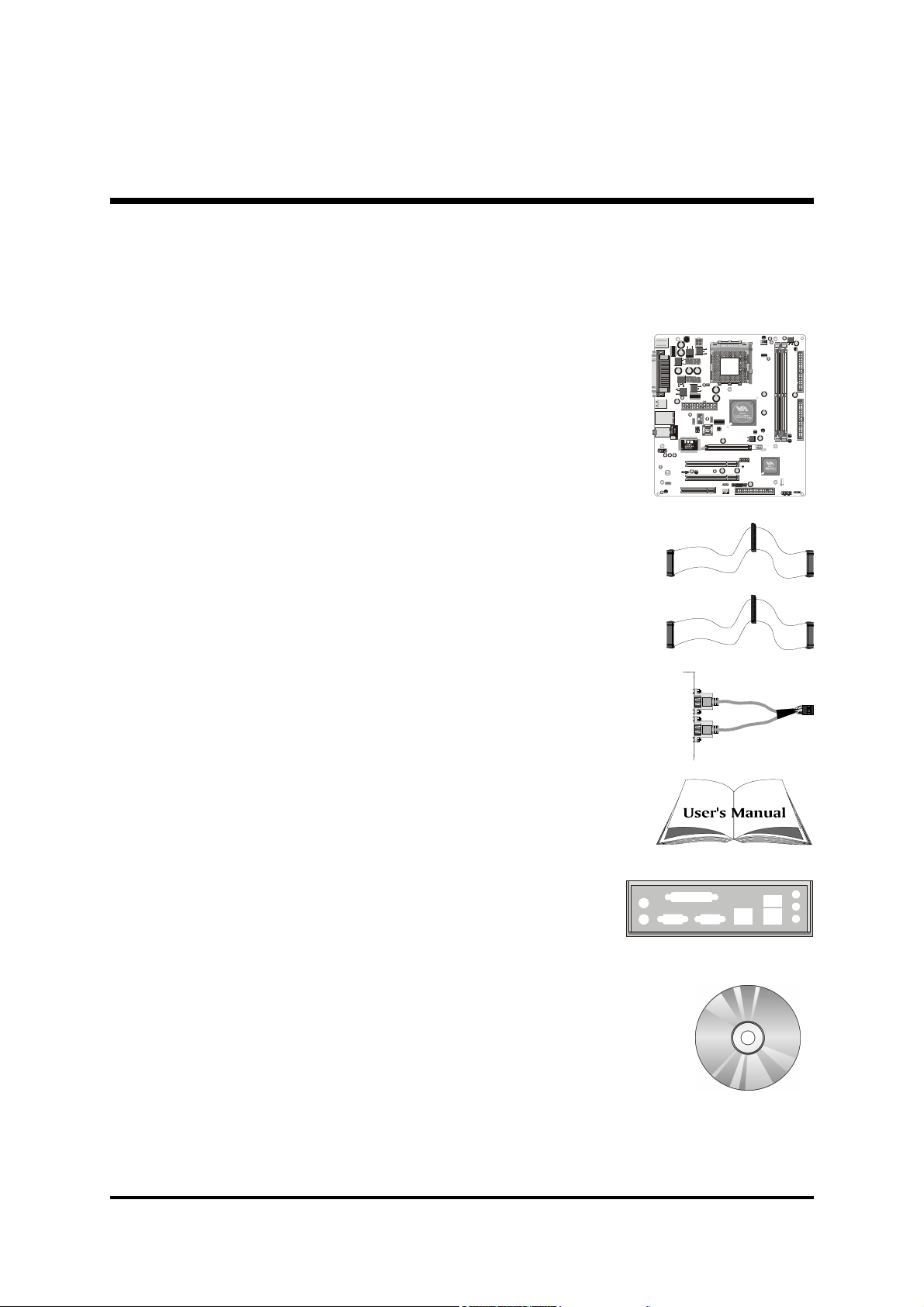
Check all items with your MK40V/MK40VN mainboard to make sure nothing
is missing. The complete package should include:
- One piece of Shuttle MK40V/MK40VN Mainboard
- One piece of ATA 133/100/66/33 Ribbon Cable
- One piece of Floppy Ribbon Cable
- One piece of twin ports USB Cable (optional)
J3
PSKBM1
COM1
LPT1
VGA1
USB1
USBLAN1
JS1
AUDIO1
1
1
1
1
Eo
N
SIR 1
JP 3
AGP1
USB2
PCI1
1
CD1
PCI2
CNR1
1
SYSTEM_FAN1
DIM2
DIM1
1
SPK1
PANEL1
- MK40V/MK40VN User's Manual
- I/O Shielding
- One piece of Bundled CD-ROM with containing:
Ø MK40V/MK40VN user's manual saved in PDF format
Ø VIA 4in1 Driver
Ø VIA VGA Driver
Ø VIA USB2.0 Driver
Ø VIA LAN Driver (MK40VN only)
Ø VIA Audio Driver
Ø AMI BIOS CMOS Setup Utility
- 7 -
Page 13

2 FEATURES
MK40V/MK40VN mainboard is carefully designed for the demanding PC user who wants
high performance and maximum intelligent features in a compact package.
2.1 Specifications
- CPU Support
Support Socket 462 package CPU.
AMD Athlon XP Processor with 200/266/333 MHz FSB.
- Chipset
Features VIA KM400 N.B. and VIA VT8235 S.B..
- Onboard Graphical Controller
The VIA KM400 integrates a full featured Unichrome I 128-bit 2D/3D AGP
controller.
- Onboard 10/100Mb/s LAN (MK40VN only)
VIA VT6103, support 10Mb/s and 100 Mb/s operation.
- AC'97 Audio Codec.
AC'97 2.1 compliant.
Spread independent PCI functions for Audio and Modem.
- CPU FSB Configuration
Soft-configuration FSB (The FSB speed is software configurable from 100MHz
to 166MHz.)
- Versatile Memory Support
Two 184-pin DIMM slots to support max 2GB of PC1600/PC2100/PC2700
compliant with DDR SDRAM module.
- PCI Expansion Slots
Provides two 32-bit PCI slots.
- AGP Expansion Slot
Provides one 32-bit AGP slot which support 4X,8X AGP device.
- 8 -
Page 14

- CNR Expansion Slot
Provides one CNR (Commnications and Networking Riser) slot to insert
special riser cards with Audio and Modem functionality.
- 6 USB 2.0 Complaint Interface Onboard
4 x USB connectors on back-panel and one set of dual USB port headers on
mid-board.
- I/O Interface
Provides a variety of I/O interfaces:
Ø Floppy interface for 3.5-inch FDD with 720KB, 1.44MB, or 2.88MB
format or for 5.25-inch FDD with 360K or 1.2MB format.
Ø 1x PS/2 Mouse Port.
Ø 1x PS/2 Keyboard Port.
Ø 1x DB25 parallel port.
Ø 1x DB9 serial port 16550 UART compatible.
Ø 1x VGA port.
Ø 4x USB 2.0 Ports.
Ø 1x LAN port. (MK40VN only)
Ø 1x Line-In port.
Ø 1x Line-Out port.
Ø 1x Mic-In port.
- PCI Bus Master IDE Controller Onboard
Two Ultra DMA 133/100/66/33 Bus Master Dual-channel IDE ports provide
support to a maximum of four IDE devices (one Master and one Slave per channel). The IDE Bus implements data transfer speeds of up to 133/100/66/33
MB/sec and also supports Enhanced PIO Modes. 80-pin Cable Backward Compatible Legacy ATAPI Devices, ATAPI IDE CD-ROM, CD-R, CD-RW, and LS120 Supports.
- ATX Power Supply Connector
ATX power supply unit can be connected to the onboard 20-pin Pentium 4
standard ATX power connectors, supporting Suspend and Soft-On/Off modes
by dual-function power button.
The Pentium 4 ATX power include other 4-pin+12V ATX power connector.
- 9 -
Page 15

- Advanced Configuration and Power Interface
Features three power saving modes: S1 (Snoop), S4 (Suspend to DISK), and S5
(Soft-Off). ACPI provides more efficient Energy Saving Features controlled by
your operating system that supports OS Direct Power Management (OSPM)
functionality.
- System BIOS
Provides licensed Award BIOS V6.0 PG on Intel Firmware Hub 2Mb Flash
core and supports Green PC, Desktop Management Interface (DMI).
- Form Factor
System board conforms to Micro ATX specification.
Board dimension: 230 mm * 200 mm.
- Advanced Features
Ø Low EMI - Built in spread spectrum. Unused PCI/SDRAM slots are shut off
by the automatic clock for reducing EMI.
Ø Dual Function Power Button - The system can be in any of the two
states: one is Suspend mode and the other is Soft-Off mode. Pushing the
power button for less than 4 seconds places the system into Suspend
mode. When the power button is pressed for longer than 4 seconds, the
system will enter Soft-Off mode.
Ø CPU Host Clock Setting - These items allow users to adjust CPU Host
Clock in BIOS.
- Intelligent Features
Ø Voltage Monitoring - Monitors various voltages of key elements, such as
the CPU, and other critical system voltage levels to ensure a stable current
passing through mainboard components.
Ø Fan Status Monitoring - To prevent the CPU from overheating, the CPU
fan is monitored by RPM, with which the cooling fan is required.
Ø Temperature Monitoring - This item allows users to make sure whether
the CPU or system runs under a suitable temperature.
- 10 -
Page 16
3 HARDWARE INSTALLATION
IDE
2
IDE
1
1
CPU_FAN1
1
FDC1
BAT1
CLEAR CMOS1
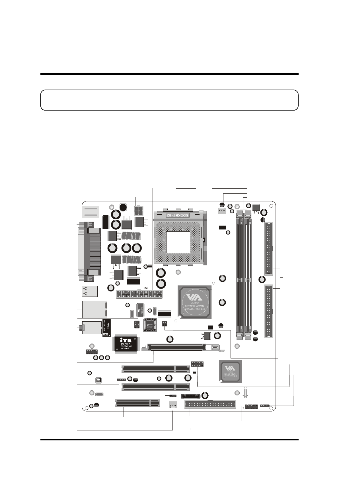
Floppy Connector-FDC1
ATX Power Connector - CN3
Socket 462
VIA KM400 Chipset
1
Before removing/installing any of these devices : CPU, DIMMs, Add-On
Cards, and Cables, please unplug the onboard power connector.
This section outlines how to install and configure your mainboard. Referring to the following mainboard layout helps you identify various jumpers, connectors, slots, and ports.
Steps described herein will lead you to a quick and correct installation of your system.
3.1 Step-by-Step Installation
Accessories Of MK40V/MK40VN
ATX 12V Power
Connector - J3
PS/2 Mouse/
PS/2 Keyboard
Connectors
COM1 Connector
Parallel Connector
VGA Connector
USB Connectors
USB Connector
&
LAN(MK40VN Only)
Connector
IR Header-SIR1
Line-In/ Line-Out/
Mic-In Connectors
Front Panel Audio
Connector-AUDIO1
One AGP Slot
Two PCI Slots
CD Header-CD1
PSKBM1
COM1
USB1
USBLAN1
JS1
1
LPT1
VGA1
AUDIO1
CPU_FAN1
Two DIMM Slots
J3
DIM1
1
1
SIR 1
PCI1
1
CD1
PCI2
Eo
AGP1
1
N
JP 3
USB2
1
1
1
DIM2
Two IDE Connectors
2
B
S
U
r
e
t
d
3
e
a
P
s
e
J
p
-
i
H
y
h
c
B
C
n
S
e
5
U
u
3
q
2
d
e
8
e
r
d
T
F
n
V
e
U
t
A
I
P
x
V
E
Speaker Connector-SP K1
C
One CNR Slot
Clear CMOS Jumper-Clear CMOS1
System Fan1
CNR1
SYSTEM_FAN1
- 11 -
Fro
PANEL1
t Pan
n
SPK1
l Hea
e
der -
PAN
L
1
E
Page 17
Step 1
SOCKET462
ASSEMBLED IN MALAYSIA
Lever
Blank
OCKET46
2
Blank
AMD CPU
Notch
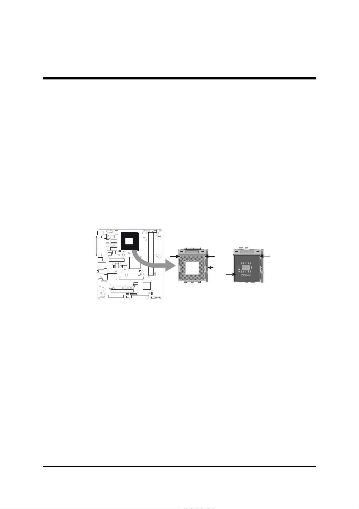
Install the CPU:
1. Locate the CPU ZIF (Zero Insertion Force) socket on the upper-right sector
of your mainboard (between the back panel connectors and the DIMM
memory slots).
2. Pull the CPU ZIF socket lever slightly sideways away from the socket to
unlock the lever, and then bring it to an upwardly vertical position.
3. Place your AMD AthlonXP processor in the socket A. Note
that the CPU's edges have been purposely designed non-symmetrically to
prevent from inserting the processor in the wrong direction. The following
diagram demonstrates the correct placement of the CPU in the ZIF socket.
You can see that the two blunt-edged corners should face towards the socket
lever.
S
4. Slightly push the AMD AthlonXP processor into the socket
without applying excessive force while making sure there is no gap between
CPU and socket. Then lower the socket-lever all the way down to its horizontal position and lock it to secure the CPU in place.
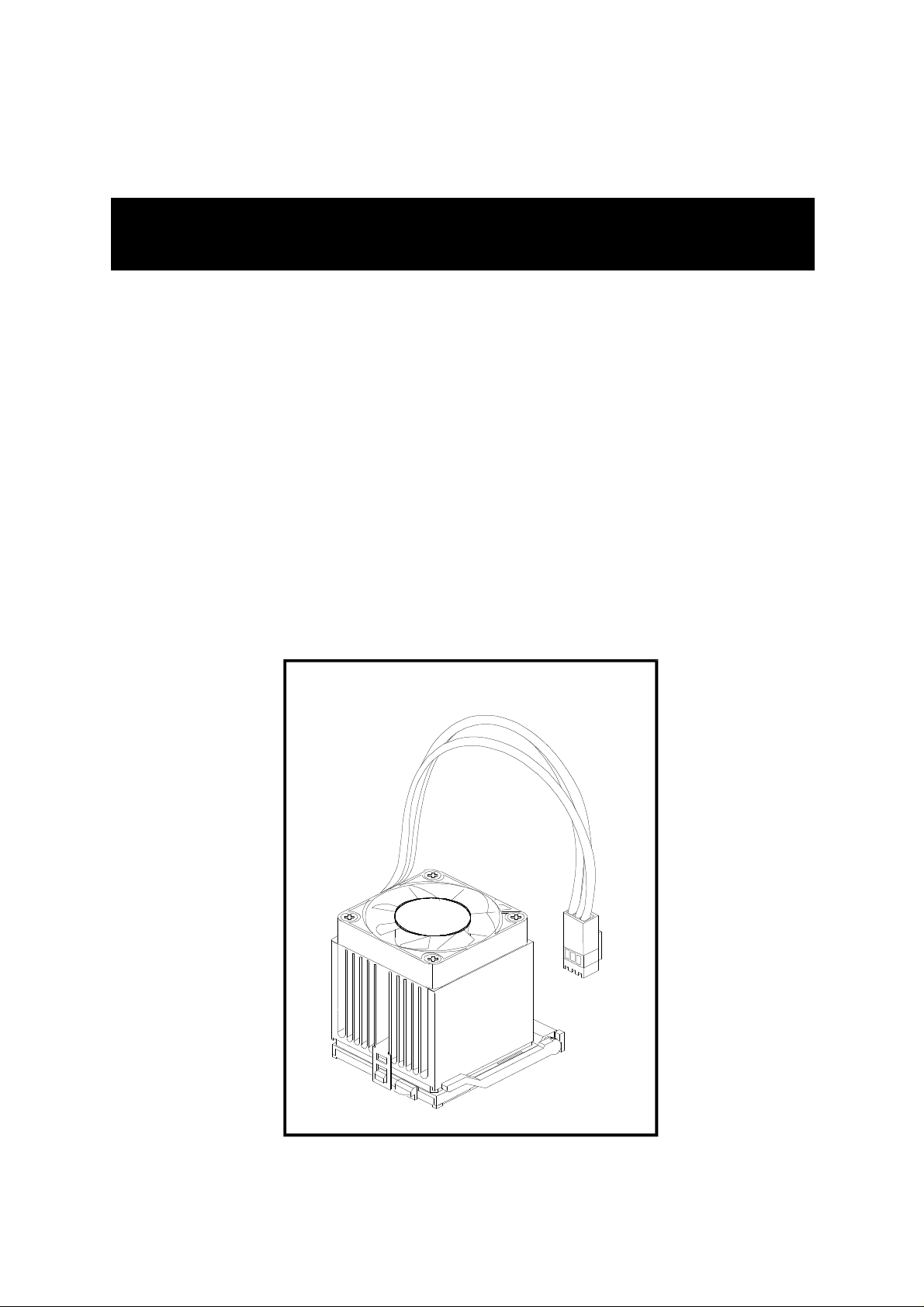
5. The AMD AthlonXP processor requires a set of heatsink/fan
to ensure proper cooling of the processor. If heatsink/fan have not been already mounted on your CPU, you must purchase the heatsink/fan separately
and have it installed. Plug the cable throught the heatsink/fan in the CPU fan
power connector located nearby. Note that there are several types of CPU
fan connectors. Normally, if your mainboard supports the hardware monitoring function, a 3-pin fan power connector should allow your system to
detect the CPU fan's speed. The CPU fan can also run with a 2-pin fan power
connector, however, detection of CPU fan's speed is not supported. Another type of CPU fan may feature a large 4-pin fan power connector, which
does not support CPU fan's speed detection and must be directly connected
to the system's power supply unit. Please refer to the following diagram.
- 12 -
Page 18

Step 2.
Set Jumpers
The default jumper settings have been set for the common usage standard of
this mainboard. Therefore, you do not need to reset the jumpers unless you
require special adjustments as any of the following cases:
1. Clear CMOS
2. CPU Frequency
For first-time DIY system builders, we recommend that you do not change the
default jumper settings if you are not totally familiar with the mainboard configuration procedures. The factory-set default settings are tuned for optimum
system performance. For the advanced users who wish to customize their system, section 3.2 Jumper Settings will provide detailed information on how to
configure your mainboard manually.
Step 3
Install DDR SDRAM System Memory
To install memory, insert DDR SDRAM memory module(s) in any one or two
DIMM banks. Note that SDRAM modules are directional and will not go in the
DIMM banks if they are not properly oriented. After the module is fully inserted
into the DIMM bank, lift the clips of both sides of the DIMM bank to lock the
module in place.
DDR SDRAM
- 13 -
Page 19

Step 4
Install Internal Peripherals in System Case
Before you install and connect the mainboard into your system case, we recommend that you first assemble all the internal peripheral devices into the computer housing, including but not limited to the hard disk drive (IDE/HDD), floppy
disk drive (FDD), CD-ROM drive, and ATX power supply unit. This will greatly
facilitate in making the connections to the mainboard described below.
To install IDE & FDD drives, follow this procedure:
1. Set the required jumpers on each device according to the instructions provided by the manufacturer. (IDE devices, HDD, and CD-ROM, have to set
jumpers to Master or Slave mode depending on whether you install more
than one device of each kind.)
2. Connect IDE cable and FDD cable on the back panel of the internal peripheral devices to the corresponding headers on board. Note that the cable
should be oriented with its colored stripe (usually red or magenta) connected
to pin#1 both on the mainboard IDE or FDD connector and on the device as
well.
3. Connect an available power cable from your system power supply unit to
the back panel of each peripheral device. Note that the power cable is directional and cannot fit in if not properly positioned.
- 14 -
Page 20

Step 5
Mount the Mainboard on the Computer Chassis
1. You may find there are a lot of mounting holes on your computer chassis
and mainboard. To match the holes on both properly, the key point is to
make the back panel of the mainboard in a close fit with your system case,as
shown below.
2. Position the studs between the chassis and the mainboard. The studs are
used to fix the mainboard and to keep a certain distance between the them,
for avoiding any electrical shorts in-between.
(If your computer case is already equipped with mounting studs, you need
to tighten the screws to attach the mainboard.)
Note: In most computer housings, you can find 4 or more holes to place studs
for fixing the mainboard. If there aren't enough matching holes, screw
at least 4 studs to ensure the proper attachment of the mainboard.
- 15 -
Page 21

Step 6
USB2
13579
2468
10
1=VREG_FP_USBPWR0
2=VREG_FP_USBPWR0
234
MSGLED
PWR
HDLED
RST
PANEL
1
Front Panel
PWR
MSGLEDHDLED
1
RST
RSVD
Connect Front Panel LEDs/Switches/USB
You can find there are several different cables already existing in the system
case and originating from the computer's front panel devices (HDLED, RST
switch, MSGLED, PWR or USB device etc.). These cables serve to connect the
front-panel LEDs, switch, and USB connectors to mainboard's front-panel connector groups (PANEL1 and USB2), as shown below.
USB2
1
1. HDD LED (HDLED)
2. Hardware Reset Switch Button (RST)
3. Green-LED (MSG LED)
4. ATX Soft Power On/Off (PWR)
5. Extended USB Header (USB2)
5
Extended USB Header
NC
NC
1
RSVD
3=USB_FP_P05=USB_FP_P0+
7=GND
9=KEY
4=USB_FP_P16=USB_FP_P1+
8=GND
10=USB_FP_OC0
- 16 -
Page 22

Step 7
111IDE2
1
FDC1
Connect IDE and Floppy Disk Drives
1. IDE cable connectors
IDE
2. Floppy cable connector
- 17 -
Page 23

Step 8
SPK1
Connect Other Internal Peripherals
1. Front panel microphone and line-out header (AUDIO1);
CD_IN connector (CD1)
AUDIO1
1
CD1
2. IR header (SIR1)
3. Internal speaker header (SPK1)
- 18 -
1
SIR1
1
Page 24

Step 9
CN3
Connect the Power Supply
1. System power connectors
Step 10
Install Add-On Cards in Expansion Slots
1. Accelerated Grapics Port (AGP) Card
J3
2. PCI Card
3. Communications and Networking Riser (CNR) Card
- 19 -
Page 25

Step 11
627
8
9
Connect External Peripherals to Back Panel
You are now ready to connect the external peripherals to your system's back
panel.
1. PS/2 Mouse Port
2. PS/2 Keyboard Port
3. Parallel Port (LPT1)
4. Serial Port (COM1)
5. VGA Port
6. USB Ports
7. LAN Port (MK40VN only)
8. Line-In Port
9. Line-Out Port
10. Mic-In Port
1
4
3
5
Step 12
First Time System Boot Up
To assure the completeness and correctness of your system installation, you
may check the above installation steps once again before you boot up your
system for the first time.
1. Insert a bootable system floppy disk (DOS 6.2x, Windows 95/98/NT, or
others) which contains FDISK and FORMAT utilities into the FDD.
2. Turn on the system power.
3. First, you must use the FDISK utility to create a primary partition of the hard
disk. You can also add an extended partition if your primary partition does
not use all of the available hard disk space. If you choose to add an extended partition, you will have to create one or more logical partitions to
occupy all the space available to the extended partition.
- 20 -
Page 26

The FDISK utility will assign a drive letter (i.e., C:, D:, E:,...) to each partition
which will be shown in the FDISK program. After FDISK procedure, reboot
your system by using the same system floppy disk.
Note : DOS 6.2x and Windows 95A can only support up to 2.1GB of HDD
partition. If you use the FDISK utility with one of the operating systems mentioned above, you can only install your HDD into partitions
no larger than 2.1GB each.
4. Now, use the FORMAT utility to format all the partitions you’ve created.
When formatting the primary partition (C:), make sure to use the FORM-
AT C: /S command.
Note : FORMAT C: /S can transfer all the necessary system files into the
primary partition of your hard disk. Then, your HDD will become
a bootable drive.
5. Install all the necessary drivers for CD-ROM, Mouse, etc.
6. Setup the complete operating system according to your OS installation
guide.
Step 13
Install Drivers & Software Components
Please note that all the system utilities and drivers are designed for Win 9x/
2000/ME/NT/XP operating systems only. Make sure your operating system is
already installed before running the drivers installation CD-ROM programs.
1. Insert the MK40V/MK40VN bundled CD-ROM into your CD-ROM drive.
The auto-run program will display the driver's main installation window
on screen.
2. Choose "Install Mainboard MK40V/MK40VN Software".
3. Choose "Install VIA 4in1 Driver" and complete it.
4. Choose "Install VIA VGA Driver" and complete it.
5. Choose "Install VIA USB2.0 Driver" and complete it.
6. Choose "Install VIA Audio Driver" and complete it.
7. Choose "Install VIA LAN Driver" and complete it. (MK40VN only)
8. Quit (from the auto-run installation program).
] Please refer to section Chapter 4 Software Utility to install driver.
- 21 -
Page 27

3.2 Jumper Settings
Several hardware settings are made through the use of mini jumpers to connect
jumper pins on the mainboard. Pin #1 could be located at any corner of each
jumper, you just find the location with a white right angle which stands for pin
#1. There are several types of pin #1 shown as below:
3-pin and multi (>3) pin jumpers shown as following:
Pin #1 to the left:
Pin #1 on the top:
Pin #1 to the right:
Pin #1 on the bottom:
Jumpers with two pins are shown as for Close [On] or for
Open [Off]. To short jumper pins, simply place a plastic mini jumpers over
the desired pair of pins.
Caution!
1. Do not remove the mainboard from its antistatic protective packaging
until you are ready to install it.
2. Carefully hold the mainboard by its edges and avoid touching its components. When putting the mainboard down, place it on top of its original packaging film, on an even surface, and components side up.
3. Wear an antistatic wrist strap or take other suitable measures to prevent
electrostatic discharge (ESD) whenever handling this equipment.
- 22 -
Page 28

Jumpers & Connectors Guide
A1E2E5D1C5D1A2
C1~C4
The following list will help you to identify jumpers, slots, and connectors
along with their assigned functions:
B1~B2
B3~B5
B6
B6~B7
E4
B8~B10
C6
E1
E2E1
E3
CPU/Memory/Expansion Slots
Socket 462 : CPU Socket for AthlonXP, 462-pin processors
DIMM1/2 : Two DIMM Slots for 128, 256, 512 MB, and 1GB of 2.5V
DDR SDRAM(The total installed memory does not exceed 2GB.)
AGP : One 4X/8X AGP (Accelerated Graphics Port) Slot
PCI : Two 32-bit PCI Expansion Slots
CNR : One CNR (Communications and Networking Riser) Slot
- 23 -
Page 29

Jumpers
A1
A2
Clear CMOS1 : Clear CMOS setting
JP3 : CPU Frequency setting
Back Panel Connectors
B1
B2
B3
B4
B5
B6
B7
B8
B9
B10
MS : PS/2 mouse port
KB : PS/2 keyboard port
COM1 : Serial port (DB9 male)
LPT1 : Parallel port (DB25 female)
VGA1 : VGA port (DB15 female)
USB : 4x USB (Universal Serial Bus) ports 1/2/3/4
LAN : 1x LAN port (MK40VN only)
LINE_IN : Line-In port
LINE_OUT : Line-Out port
MIC_IN : Mic-In port
Front Panel Connectors
C1
C2
HDLED : IDE drive active LED
RST : Hardware reset switch
C3
C4
C5
C6
MSG LED : Green LED
PWRSW : ATX power on/off momentary type switch
USB2 : Extended USB header
AUDIO1 : Front-panel audio header
Internal Peripheral Connectors
D1
D1
D1
IDE1 : IDE primary interface (Dual-channel)
IDE2 : IDE secondary interface (Dual-channel)
FDC1 : Floppy disk drive interface
Other Connectors
E1
E2
E2
E3
E4
E5
J3/CN3 : ATX power connector
CPUFAN1 : CPU fan connector
SYSTEMFAN1 : System fan connector
CD1 : CD_IN connector
SIR1 : IR header
SPK1 : Internal speaker header
- 24 -
Page 30

F Jumpers
A1
Clear CMOS Setting (Clear CMOS1)
Clear CMOS1 is used to clear CMOS data. Clearing CMOS will result in the
permanently erasing previous system configuration settings and the restoring
original (factory-set) system settings.
1
Pin 1-2 (Normal)
1
Pin 2-3 (Clear CMOS)
Step 1. Turn off the system power (PC-> Off).
Step 2. Remove ATX Power cable from ATX Power connector.
Step 3. Remove jumper cap from pins 1-2.
Step 4. Place the jumper cap on pins 2-3 for a few seconds.
Step 5. Return the jumper cap to pins 1-2.
Step 6. Plug ATX Power cable into ATX Power connector.
Step 7. Turn on the system power (PC-> On).
A2
CPU Frequency Setting (JP3)
JP3 are used to set the CPU frequency (100MHz to 166 MHz) according to the
CPU.
CPU
Frequency
Pins 1-2 Pins 3-4
Clear CMOS1
1
133 MHz Off Off
166 MHz Off On
100 MHz On Off
200MHz
(Reserve)
On On
- 25 -
JP3
1
2
Page 31

F Back Panel Connectors
B1
PS/2 Mouse & PS/2 Keyboard Port
Connectors
B2
Two 6-pin female PS/2 Mouse & Keyboard
connectors are located at the rear panel of
the mainboard. Depending on the computer housing you use (desktop or tower),
the PS/2 Mouse connector is situated at the
top of the PS/2 Keyboard connector when
the mainboard is laid into a desktop, as opposed to a tower where the PS/2 Mouse
connector is located at the right of the PS/2
Keyboard's. Plug the PS/2 Mouse and Keyboard jacks into their corresponding connectors.
B3
COM1 Port Connector
PS/2 Mouse
PS/2 Keyboard
Attach a serial device cable to the DB9 serial port COM1 at the back panel of your
computer.
B4
Parallel Port Connector
One DB25 female parallel connector is located at the rear panel of the mainboard.
Plug the connection cable from your parallel device (printer, scanner, etc.) into this
connector.
B5
VGA Port Connector
One 15-pin VGA connector is located at
the rear panel of the mainboard.
COM1 Port
Parallel Port
VGA Port
- 26 -
Page 32

B6
USB1/2/3/4 Port Connectors
This mainboard offers 4 USB ports on back
panel. Plug each USB device jack into an
available USB1/2/3/4 connector.
USB Port2
USB Port4
B7
LAN Port Connector (MK40VN only)
This mainboard can accommodate one
device on LAN. Attach RJ-45 cable to this
port connector to your PC to the LAN.
B8
Line-In Port Connector
Line-In is a stereo line-level input port that
accepts a 1/8-inch TRS stereo plug. It can
be used as a source for digital sound recording.
B9
Line-Out Port Connector
Line-Out is a stereo output port through
which the combined signal of all internal
and external audio sources on the board
is output. It can be connected to 1/8-inch
TRS stereo headphones or to amplified
speakers.
USB Port1
USB Port3
LAN Port
Line-In Port
Line-Out Port
B10
Mic-In Port Connector
Mic-In is a 1/8-inch jack that provides a
mono input. It can use a dynamic mono
or stereo microphone with a resistance of
not more than 600 Ohms.
Mic-In Port
- 27 -
Page 33

F Front Panel Connectors
PANEL
1
PWR
MSGLE
D
HDLED
1
RST
RSVD
PANEL
1
PWR
MSGLE
D
HDLED
1
RST
RSVD
C1
HDD LED Connector (HDLED)
Attach a connector cable from the IDE device LED to the 2-pin (HDLED) header.
The HDD LED lights up whenever an IDE device is active.
Note : Please notice all the LED connectors are directional. If your chassis's
LED does not light up during running, please change it to the opposite
direction.
NC
C2
Hardware Reset Connector (RST)
Attach a cable to the 2-pin (RST) header. Pressing the reset switch causes the
system to restart.
- 28 -
NC
Page 34

C3
PANEL
1
PWR
MSGLE
D
HDLED
1
RST
RSVD
PANEL
1
PWR
MSGLE
D
HDLED
1
RST
RSVD
MSG LED Connector (MSGLED)
Connecting MSG LED a single- or dual-color, front panel mounted LED provides power on/off, sleep and message waiting indication.
C4
ATX Power On/Off Switch Connector (PWR)
NC
The Power On/Off Switch is a momentary type switch used for turning on or off
the ATX power supply. Attach a connector cable to the 2-pin (PWRSW) header
on the mainboard.
NC
- 29 -
Page 35

C5
3 =AUD_MIC_BIAS
Pin Assignments:
Extended USB Header (USB2)
The header is used to connect the cable attached to a USB connector which is
mounted on front panel or back panel. But the USB cable is optional at the time
of purchase.
Pins Assignment:
1=VREG_FP_USBPWR0
2=VREG_FP_USBPWR0
3=USB_FP_P04=USB_FP_P15=USB_FP_P0+
6=USB_FP_P1+
7=GROUND
8=GROUND
9=KEY
10=USB_FP_OC0
C6
Front Panel Audio Header (AUDIO1)
USB2
2
1
This header allows users to install an auxiliary Front-Oriented Microphone and
Line-Out port for easier access. Either the Line-Out port connector on back
panel or AUDIO1 header is available at the same time. If you would like to use
this header on front panel, please remove all jumpers from this header and
install your special extra microphone and line-out cable instead. Two mini jumpers must be setted on pins 5-6 and pins 9-10, when this header is not used.
1 =AUD_MIC
2 =AUD_GND
4 =AUD_VCC
5 =AUD_FPOUT_R
6 =AUD_RET_R
7 =HP_ON
8 =KEY
9 =AUD_FPOUT_L
10=AUD_RET_L
AUDIO1
2468
13579
10
AUDIO1
1
- 30 -
Page 36

F Internal Peripheral Connectors
1
FDC1
1IDE2
Enhanced IDE and Floppy Connectors (IDE1/IDE2 & FDC1)
D1
The mainboard features two 40-pin dual-channel IDE device connectors (IDE1/
IDE2), providing support for up to four IDE devices, such as CD-ROM and
Hard Disk Drive (HDD).
This mainboard also includes one 34-pin Floppy Disk Controller (FDC1) to
accommodate the Floppy Disk Drive (FDD). Moreover, this mainboard comes
with one 80-pin ATA 133/100/66/33 ribbon cable to connect IDE HDD, and
one 34-pin ribbon cable for FDD connection.
IDE1
1
Important : Ribbon cables are directional; therefore, connect the red
cable stripe to the same side.
- 31 -
Page 37

F Other Connectors
CN3
E1
ATX Power Supply Connector (J3 & CN3)
This motherboard uses 20-pin Pentium 4 standard ATX power header, and J3
with 1x4-pin +12V PC ATX power supply headers.
Please make sure you plug it in the right direction.
J3
CN3
A traditional ATX system remains in the power-off stage when AC power resumes from power failure. However, it is inconvenient for a network server or
workstation if there is not an UPS to execute power-on. Thus, this motherboard
supports an AC Power Auto Recovery function to solve this problem. You may
enable the function, "Restore on AC/power loss" in the sub-menu of "Power
Management Setup" within the BIOS setup program.
J3
Note 1 : The ATX power connector is directional and will not go in
unless the guides match perfectly, making sure that pin#1 is
properly positioned.
Note 2 : Make sure the latch of the ATX power connector clicks into
place to ensure a solid attachment.
Note 3 : Your ATX power supply must be supplied to ACPI+5V
standby power and at least 720mA compatible.
Note 4 : Make sure your power supply have enough power for higher
speed processor installed.
- 32 -
Page 38

E2
GND
+12V
SENSE
CPU_FAN1
CD1
CPU and System Fan Connectors (CPUFAN1/SYSTEMFAN1)
The mainboard provides two onboard 12V cooling fan power connectors to
support CPU (CPUFAN1) and System (SYSTEMFAN1) cooling fans.
1
Note : Both cable wiring and type of plug may vary, which depend on the fan
maker. Keep in mind that the red wire should always be connected to
the +12V header and the black wire to the ground (GND) header.
E3
Audio CD_IN Connector (CD1)
1
SYSTEM_FAN1
1
Port CD1 is used to attach the audio connector cable from the CD-ROM/DVDROM drive.
1
2 431
Pin Assignments:
1=CD IN L
2=GND
3=GND
4=CD IN R
CD1
1
- 33 -
Page 39

E4
SPK1
SPK1
1 2 3 4
Pin Assignments:
4=+5V
SIR1
Pin Assignments:
6=IRRX
E4
IR Header (SIR1)
If you have an Infrared device, this mainboard can implement IR transfer
function. This mainboard supports Normal or IrDA transfer mode. To enable
this function, attach a 6-pin infrared device cable to the IR (SIR1) header, and
refer to the diagram below for the IR pin assignments.
1
3
5
1=NC
2=KEY
3=+5V
4=GND
5=IRTX
E5
Internal Speaker Header (SPK1)
2
4
6
Attach the PC speaker cable from the case to the 4-pin speaker connector
(SPK1).
1
SIR1
1
1=SPKR
2=NC
3=GND
1
- 34 -
Page 40

3.3 System Memory Configuration
The MK40V/MK40VN mainboard has two 184-pin DIMM banks that allow
you to install from 128MB up to 2GB of system memory. Each 184-pin DIMM
(Dual In-line Memory Module) bank can accommodate 128MB, 256MB,
512MB, and 1GB of PC1600/PC2100/PC2700 compliant 2.5V single or double
side DDR SDRAM modules. DIMM slots are arranged in two banks, each
memory bank made of one bank and providing a 64-bit wide data path.
1. Install Memory:
Install memory in any or all of the banks. The combination shown as follows.
DIMM Socket Memory Modules
DIMM 1
DIMM 2
128MB, 256MB, 512MB, and 1GB 184-pin 2.5V DDR
SDRAM DIMM
128MB, 256MB, 512MB, and 1GB 184-pin 2.5V DDR
SDRAM DIMM
Module
Quantity
x 1
x 1
Note : The total installed memory does not exceed 2GB.
Note: You do not need to set any jumper to configure memory since theBIOS
utility can detect the system memory automatically. You can check the
total system memory value in the BIOS Standard CMOS Setup menu.
2. Upgrade Memory:
You can easily upgrade the system memory by inserting additional DDR SDRAM
modules in available DIMM banks. The total system memory is calculated by
simply adding up the memory in all DIMM banks. After upgrade, the new system memory value will automatically be computed and displayed in the field
"Standard CMOS Setup" of BIOS setup program.
- 35 -
Page 41

4 SOFTWARE UTILITY
4.1 Mainboard CD Overview
Note : The CD contents attached in MK40V/MK40VN mainboard
are subject to change without notice.
To start your mainboard CD disc, just insert it into your CD-ROM drive and the
CD AutoRun screen should appear.
If the AutoRun screen does not appear, double click or run D:\Autorun.exe
(assuming that your CD-ROM drive is drive D:).
Navigation Bar Description:
F Install Mainboard MK40V Software -Installing VIA 4in1, VIA VGA ,
VIA USB2.0 and VIA Audio Drivers.
F Install Mainboard MK40VN Software - Installing VIA 4in1, VIA VGA,
VIA USB2.0, VIA LAN and VIA Audio Drivers.
F Install Utility - Installing Acrobat Reader, WinFlash Utility
F Manual - MK40V/MK40VN user's manual in PDF format.
F Link to Shuttle Homepage - Link to shuttle website homepage.
F Browse this CD - Allows you to see contents of this CD.
F Quit - Close this CD.
- 36 -
Page 42

4.2 Install Mainboard Software
Insert the attached CD into your CD-ROM drive and the CD AutoRun screen
should appear. If the AutoRun screen does not appear, double click on Autorun
icon in My Computer to bring up Shuttle Mainboard Software Setup
screen. Use your pointing device (e.g. mouse) on the "Install Mainboard
MK40V Software" bar to run into sub-menu. The software includes:
[4.2.A] Install VIA 4in1 Driver [4.2.C] Install VIA USB2.0 Driver
[4.2.B] Install VIA VGA Driver [4.2.D] Install VIA Audio Driver
MK40V
Or use your pointing device (e.g. mouse) on the "Install Mainboard MK40VN
Software" bar to run into sub-menu. The software includes:
[4.2.A] Install VIA 4in1 Driver [4.2.D] Install VIA LAN Driver
[4.2.B] Install VIA VGA Driver [4.2.E] Install VIA Audio Driver
[4.2.C] Install VIA USB2.0 Driver
MK40VN
- 37 -
Page 43

4.2.A Install VIA 4in1 Driver
Select using your pointing device (e.g. mouse) on the "Install VIA 4in1 Driver"
bar to install the chipset driver.
MK40V
MK40VN
Once you made your selection, a Setup window run the installation automatically. When the copying files is done, make sure you reboot the system to take
the installation effect.
- 38 -
Page 44

4.2.B Install VIA VGA Driver
Select using your pointing device (e.g. mouse) on the "Install VIA VGA
Driver" bar to install the VGA driver.
MK40V
MK40VN
Once you made your selection, a Setup window run the installation automatically. When the copying files is done, make sure you reboot the system to take
the installation effect.
- 39 -
Page 45

4.2.C Install VIA USB2.0 Driver
Select using your pointing device (e.g. mouse) on the "Install VIA USB2.0
Driver" bar to install the USB2.0 driver.
MK40V
MK40VN
Once you made your selection, a Setup window run the installation automatically. When the copying files is done, make sure you reboot the system to take
the installation effect.
- 40 -
Page 46

4.2.D Install VIA Audio Driver
Select using your pointing device (e.g. mouse) on the "Install VIA Audio
Driver" bar to install the audio driver.
MK40V
MK40VN
Once you made your selection, a Setup window run the installation automatically. When the copying files is done, make sure you reboot the system to take
the installation effect.
- 41 -
Page 47

4.2.E Install VIA LAN Driver (MK40VN only)
Select using your pointing device (e.g. mouse) on the "Install VIA LAN Driver"
bar to install the LAN driver.
MK40VN
Once you made your selection, a Setup window run the installation automatically. When the copying files is done, make sure you reboot the system to take
the installation effect.
- 42 -
Page 48

4.3 View the User's Manual
Select using your pointing device (e.g. mouse) on the "Manual" bar. Click on
the "Install Acrobat Reader" bar if you need to install it, or click on "Manual"
bar to view MK40V/MK40VN user's manual.
- 43 -
Page 49

5 BIOS SETUP
MK40V/MK40VN BIOS ROM has a built-in Setup program that allows users to
modify the basic system configuration. This information is stored in batterybacked RAM so that it retains the Setup information even if the system power is
turned off.
The system BIOS is managing and executing a variety of hardware related functions in the system, including:
System date and time
Hardware execution sequence
Power management functions
Allocation of system resources
5.1 Enter the BIOS
To enter the BIOS (Basic Input / Output System) utility, follow these steps:
Step 1. Power on the computer, and the system will perform its
POST (Power-On Self Test) routine checks.
Step 2. Press <Del> key immediately, or at the following message:
Press DEL to enter SETUP, or simultaneously press <Ctrl>,
<Alt>, <Esc> keys
Note1. If you miss trains of words mentioned in step2 (the message dis-
appears before you can respond) and you still wish to enter BIOS
Setup, restart the system and try again by turning the computer
OFF and ON again or by pressing the <RESET> switch located
at the computer’s front-panel. You may also reboot by simultaneously pressing the <Ctrl>,<Alt>, <Del> keys simultaneously.
Note2. If you do not press the keys in time and system does not boot, the
screen will prompt an error message, and you will be given the
following options:
"Press F1 to Continue, DEL to Enter Setup”
Step 3. As you enter the BIOS program, the CMOS Setup Utility will
prompt you the Main Menu, as shown in the next section.
- 44 -
Page 50

Note: The content of this manual is subject to any change without notice
in advance.
5.2 The Main Menu
Once you enter the AMI BIOS CMOS Setup Utility, the Main Menu will
appear on the screen. The Main Menu allows you to select from several
setup functions and exit choices. Use the arrow keys to select among the
items and press <Enter> to accept and enter the sub-menu.
Note that a brief description of each highlighted selection appears at the
bottom of the screen.
Setup Items
The main menu includes the following main setup categories. Recall
that some systems may not include all entries.
Standard CMOS Setup
Use this menu for basic system configuration.
Advanced Setup
Use this menu to set the Advanced information available on your
system.
Power Management Setup
Use this menu to specify your settings for power management.
- 45 -
Page 51

PCI / Plug and Play Setup
Use this menu to sets some of parameters for devices installed on the
PCI bus and devices that use the system plug and play capability.
Load Optimal Settings
If you select this item and press Enter a dialog box apperars. If you
press Y, and then Enter, the Setup Utility loads a set of fail-safe default
values. These default values are not very demanding and they should
allow your system to function with most kinds of hardware and memory
chips.
Load Best Performance Settings
If you select this item and press Enter a dialog box apperars. If you
press Y, and then Enter, the Setup Utility loads a set of best-performance default values. These default values are quite demanding and
your system might not function properly if you are using slower chips or
other low-performance components.
Features Setup
Use this menu to sets some of the parameters for peripheral devices
connected to the system.
CPU PnP Setup
Use this menu to lets you manually configure the mainboard for thw
CPU.
Hardware Mointor
Use this menu to sets some of the parameters for the hardware monitoring function of this mainboard.
Change Password
Use this menu to change, set, or disable supervisor/user password. It
allows you to limit access to the system and Setup, or only to Setup.
Exit
Save CMOS value changes in CMOS and exit from setup.
- 46 -
Page 52

@ Standard CMOS Setup
The items in Standard CMOS Setup are divided into 8 categories. Each
category includes no, one or more than one setup items. Use the arrow
keys to highlight the item and then use the <PgUp> or <PgDn> keys
to select the value you want in each item.
Date (mm : dd : yyyy)
Set the system date. Note that if you are running a Windows OS, this
items are automatically updated whenever you make changes to the
Windows Date.
Time (hh : mm : ss)
Set the system time. The time is converted based on the 24-hour military-time clock. For example, 5:00:00 p.m. is 17:00:00.
Pri/Sec Master/Slave
Press <Enter> to enter the sub-menu of detailed options.
Floppy Drive A/DriveB
Select the type of floppy disk drive and installed in your system.
Ø The choice: Not Installed, 1.2MB, 5.25 in, 720KB, 3.5 in, 1.44MB,
3.5 in, or 2.88M, 3.5 in.
- 47 -
Page 53

******************************************************
IDE Adapters
The IDE adapters control the hard disk drive. Use a separate sub-menu to
configure each hard disk drive.
IDE HDD Auto-Detection
Press <Enter> to auto-detect HDD on this channel. If detection is suc-
cessful, it fills the remaining fields on this menu.
IDE Primary Master
Selecting 'Manual' lets you set the remaining fields on this screen and
select the type of fixed disk.
Ø The choice: None, Auto, or Manual.
Access Mode
Choose the access mode for this hard disk.
Ø The choice: CHS, LBA, Large, or Auto.
Capacity
Disk drive capacity (Approximated). Note that this size is usually slightly
greater than the size of a formatted disk given by a disk checking program.
The following options are selectable only if the 'IDE Primary Master'
item is set to 'Manual', and the 'Access Mode' item is set to 'CHS'.
Cylinder
Set the number of cylinders for this hard disk.
ØMin = 0, Max = 65535
Head
Set the number of read/write heads.
ØMin = 0, Max = 255
Precomp
Warning: Setting a value of 65535 means no hard disk.
ØMin = 0, Max = 65535
Landing Zone
Set the Landing Zone size.
ØMin = 0, Max = 65535
Sector
Number of sector per track.
ØMin = 0, Max =255
- 48 -
Page 54

@ Advanced Setup
This section allows you to configure your system for basic operation.
Quick Boot.
This item enables/disables the system starts up more quickly/slowly be
elimination some of the power on test routines.
Ø The choice: Enabled or Disabled.
1st/ 2nd/ 3
Use these three items to select the priority and order of the devices
that your system searches for an operating system at start-up time.
Ø The choice: IDE 0~3, Floppy, ARMD-FDD/,ARMD-HDD,
Try Other Boot Device
If you enable this item, the system searches all other possible loca
tions for and operating system if it fails to find one in the devices
specified under the First, Second, and Third boot devices.
Ø The choice: Yes or No.
S.M.A.R.T. for Hard Disks
Enable this item if any IDE hard disks support the S.M.A.R.T. (Self-
Monitoring, Analysis and Reporting Technology) feature.
Ø The Choice: Enabled or Disabled.
rd
Boot Device
CD/DVD-0~3, SCSI, Network, BBS-0~9, USB FDD,CDROM,
HDD, RMD-FDD,RMD-HDD or Disabled.
- 49 -
Page 55

BootUp Num-Lock
This item defines if the keyboard Num Lock key is active when your
system is started.
Ø The choice: Off or On.
Floppy Drive Swap
If you have two floppy diskette drives in your system, this item allows
you to swap the assigned drive letters so that drive A becomes drive
B, and drive B becomes drive A.
Ø The choice: Enabled or Disabled.
Floppy Drive Seek
If this item is enabled, it checks the size of the floppy disk drives at
start-up time. You don't need to enable this item unless you have a
legacy diskette drive with 360k capacity.
Ø The choice: Enabled or Disabled.
Password Check
If you have entered a password for the system, use this item to deter
mine, if the password is required to enter the Setup Utility (Setup) or
required both at start up and to enter the Setup Utility ( Always).
Ø The choice: Setup or Always.
Boot to OS/2 > 64MB
This item is only required if you have installed more than 64 MB of
memory and you are running the OS/2 operating system. Otherwise,
leave this item at the default.
Ø The choice: Yes or No.
L2 Cache
Leave these items enabled since all the processors that can be in
stalled on this board have internal L2 cache memory.
Ø The choice: Enabled or Disabled.
System BIOS Cacheable
If you enable this item, a segment of the system BIOS will be copied
to main memory for faster execution.
Ø The choice: Enabled or Disabled.
- 50 -
Page 56

Graphic Win Size
This item defines the size of aperture if you use a graphic adapter.
Ø The choice: 4MB, 8 MB, 16MB, 32MB, 64MB, 128MB or
256MB.
SDRAM Timing by SPD
This item enables or disables the SDRAM timing defined by the
Serial Presence Detect electrical.
Ø The choice: Enabled or Disabled.
SDRAM CAS# Latency
This item determines the operation of SDRAM memory CAS (column
address strobe). It is recommended that you leave this item at the
default value.
Ø The choice: 1.5, 3.0, 2.5 or 2.
SDRAM Bank Interleave
Enable this item to increase SDRAM memory speed. When enabled,
separate memory banks are set of odd and even addresses, and
upcoming byte of memory is accessible while refreshing the current
byte.
Ø The choice: 2-way/ 4-way or Disabled.
Auto detect DIMM/PCI Clk
When this item is enabled, BIOS will disable the clock signal of free
DIMM/ PCI slots.
Ø The choice: Enabled or Disabled.
Spread Spectrum
If you enable spread spectrum, it can significantly reduce the EMI
(Electro Magnetic Interference) genered by the system.
Ø The choice: Enabled or Disabled.
- 51 -
Page 57
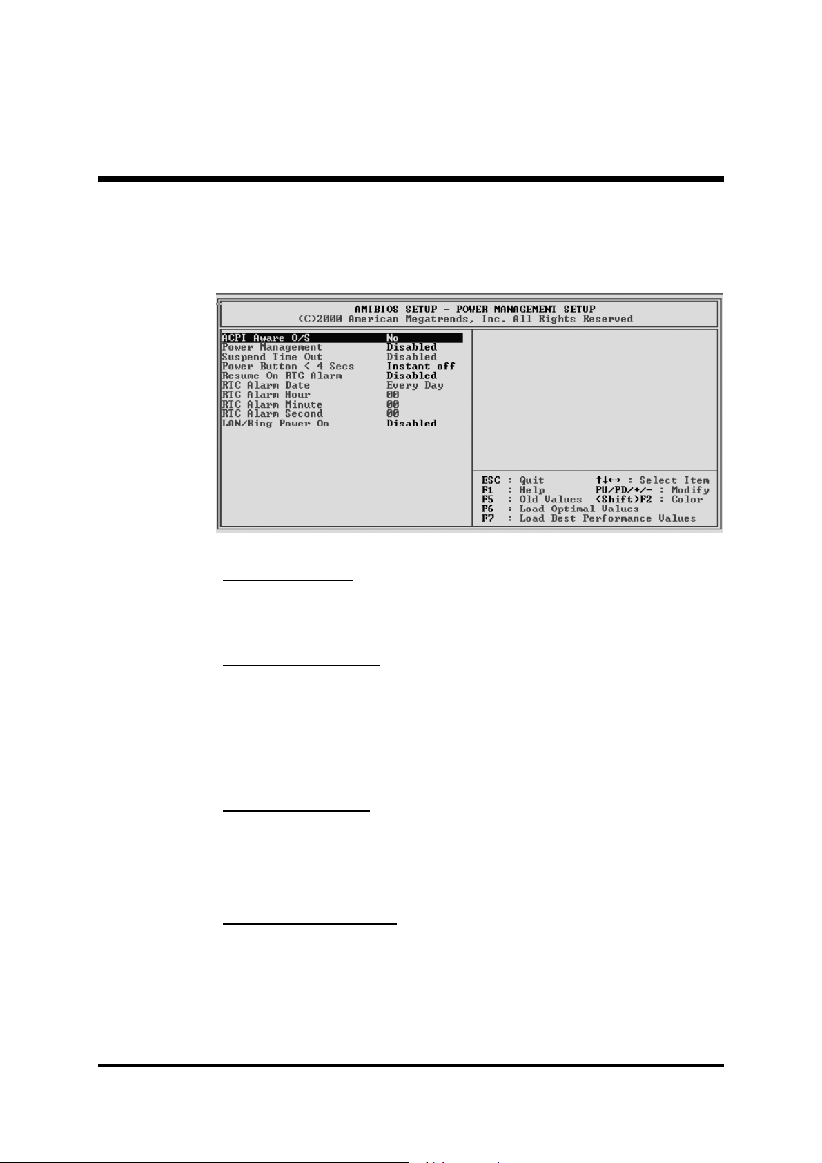
@ Power Management Setup
The Power Management Setup allows you to configure your system to
most effectively saving energy.
ACPI Aware O/S
Enable this item if you are using an O/S that supports ACPI function
such as Windows 98/ ME/ 2000.
Ø The choice: Yes or No.
Power Management
This item acts like a master switch for the power-saving modes and
hard disk timeouts. If this item is set to Max Saving, power-saving
modes occur after a short timeout. If it is set to Min Saving, powersaving modes occur after a longer timeout. If it is set to User Define,
you can insert your own timeouts for the power-saving modes.
Ø The choice: Enabled or Disabled.
Suspend Time Out
When this item is not disabled and after the setup time of
system inactivity, all devices except the CPU will be shut off.
Ø The choice: Disabled, 1 Min, 2 Min, 4 Min, 6 Min, 8 Min,
10 Min, 20 Min, 30 Min, 40 Min, or 60 Min.
PWR Button < 4 secs
Under ACPI you can create a software power down. In a software
power down, the system can be resumed by Wake UP Alarms. This
item lets you install a software power down that is controlled by the
power button on your system. If the item is set to Instant-Off, then the
power button causes a software power down. If the item is set to Delay
- 52 -
Page 58

4 Sec, then you have to hold the power button down for 4 seconds to
cause a software power down.
Ø The choice: Delay 4 Sec or Instant-Off.
Resume On RTC Alarm Date/ Hour/ Minute/ Second
When Enabled, set the date and time of the RTC (Real-Time Clock)
alarm will awaken the system from a suspend mode.
Ø The choice: Disabled or Enabled.
Date (of Month)
This item selects the alarm date.
Ø Key in a DEC number: Min=0, Max=31.
Resume Time (hh:mm:ss)
This item selects the alarm time.
[hh] Ø Key in a DEC number: Min=0, Max=23.
[mm] Ø Key in a DEC number: Min=0, Max=59.
[ss] Ø Key in a DEC number: Min=0, Max=59.
LAN/ Ring Power On
The system can be turned off with a software command. If you enable
this item, the system can automatically resume if there is an incoming
call on the Modem. You must use an ATX power supply in order to use
this feature.
Ø The choice: Enabled or Disabled.
- 53 -
Page 59

@ PCI/ Plug and Play Setup
These items set some of the parameters for devices installed on the PCI
bus and devices that use the system plug and play capability.
Share Memory size
This item lets you allocate a portion of the main memory for the
onboard VGA display application.
Ø The Choice: 8MB, 16MB, 32MB, 64MB or None.
Primary Graphics Adapter
This item indicates if the primary graphics adapter uses the PCI or the
AGP bus. The default PCI setting still lets the onboard display work and
allows the use of a second display card installed in a PCI slot.
Ø The Choice: PCI or AGP.
Allocate IRQ to PCI VGA
If this item is enabled, an IRQ will be assigned to the PCI VGA graphics
system. You set this value to No to free up an IRQ.
Ø The choice: Yes or No.
PCI IDE BusMaster
This item enables or disables the DMA under DOS mode. We recommend you to leave this item at the default value
Ø The choice: Enabled or Disabled.
@ Load Optimal Settings
Pressing <Enter> on this item asks for confirmation: Load Optimal
Settings (Y/N) ? Y
Pressing 'Y' loads a set of fail-safe default values. These default values
are not very demanding and they should allow your system to function
with most kinds of hardware and memory chips.
- 54 -
Page 60

@ Load Best Performance Settings
Pressing <Enter> on this item asks for confirmation: Load Best Performance Settings (Y/N) ? Y
Pressing 'Y' loads a set of best-performance default values. These default values are quite demanding and your system might not function
properly if you are using slower memory chips or other low-performance components.
@ Features Setup
These items set some of the the parameters for peripheral devices
connected to the system.
OnBoard FDC
Use this item to enable or disable the onboard floppy disk drive inter
face.
Ø The choice: Auto, Enabled or Disabled.
OnBoard Serial PortA
Use this item to enable or disable the onboard COM1 serial port, and to
assign a port address.
Ø The choice: Auto, Disabled, 3FB/COM1 /2FB/COM2/ 3E8/COM3/
2E8/COM4.
OnBoard IR Port
Use this item to enable or disable the onboard infrared port, and to
assign a port address.
Ø The choice: IrDA, ASKIR or Disabled.
- 55 -
Page 61

OnBoard Parallel Port
Use this item to enable or disable the onboard LPT1 port mode, and
to assign a port address.
Ø The choice: 378, 278, 3BC, Auto or Disabled.
Parallel Port Mode
Use this item to set the onboard parallel port mode.
Ø The choice: SPP (Standard Parallel Port), ECP (Extended Capabili
ties Port), EPP (Enhanced Parallel Port) or ECP+EPP.
Parallel Port IRQ
Use this item to assign IRQ to the parallel port.
Ø The choice: IRQ 5 or IRQ 7.
Parallel Port DMA
Use this item to assign a DMA channel to the parallel port.
Ø The choice: 0, 1 or 3.
OnBoard PCI IDE
This item enables or disables either or both of the onboard Primary and
Secondary IDE channels.
Audio Device
Use this item to set the onboard AC'97 audio chip.
Ø The choice: Enabled or Disabled.
Modem Device
Use this item to set the onboard AC'97 modem chip.
Ø The choice: Auto, Enabled or Disabled.
Ethernet Device
Use this item to set the onboard AC'97 Ethernet LAN.
Ø The choice: Enabled or Disabled.
OnBoard USB Function
Enable this item if you plan to use the USB ports on this mainboard.
Ø The choice: Enabled or Disabled.
USB Function for DOS
Enable this item if you plan to use the USB ports on this mainboard in
a DOS environment.
Ø The choice: Enabled or Disabled.
- 56 -
Page 62

@ CPU PnP Setup
Use this menu to lets you manually configure the mainboard for thw CPU.
The system will automatically detect the kind of CPU that you have
installed and make the appropriate adjustments to the items.
CPU Over-Clocking Func.
This item allows you to set the CPU over-clocking function.
Ø The choice: Enabled or Disabled.
CPU/DRAM Frequency Ratio
This item allows you to set the CPU/ DRAM frequency.
Ø The choice: 167~198.
CPU Over-Clocking Frequency.
This item allows you to set the CPU over-clocking frequency.
Ø The choice: Auto, CPU+0, CPU+33 or CPU+66.
- 57 -
Page 63

@ Hardware Monitor
Use this menu to sets some of the parameters for the hardware monitoring function of this mainboard.
CPU/System Temperature
This item display CPU and sytem temperature measurement.
FANs & Voltage Measurements
These items indicate cooling fan speeds in RPM and the various system
voltage measurements.
@ Change Password
Use this menu to change, set, or disable supervisor/user password. It
allows you to limit access to the system and Setup, or only to Setup.
- 58 -
Page 64

@ Exit
Steps to set supervisor/user password are described as follows:
New Password Setting:
1. While pressing <Enter> to set a password, a dialog box appears to
ask you enter a password.
2. Key in a new password that can not exceed eight characters.
3. System will request you to confirm the new password again.
4. When completed, new code takes effect.
No Password Setting:
If you want to disable the password, just press <Enter> as a password
input is requested.
If You Forget Password:
If you forget the password, the only way to access the system is to clear
the CMOS memory. Please refer to page 25 on clear CMOS setting.
Pressing <Enter> on this item asks for confirmation: SAVE to CMOS
and EXIT (Y/N) ? Y
Pressing 'Y' stores the selections made in the menus of CMOS. Next
time you boot your computer, the BIOS configures your system according to the Setup selections stored in CMOS. After saving the values, the
system is restarted again.
- 59 -
 Loading...