


ME21
FC-PGA/PPGA Celeron
and FC-PGA Pentium III Processor
Based AGPset MAIN BOARD
User's Manual

Shuttle ME21
FC-PGA/PPGA Celeron and FC-PGA Pentium III processor
based AGPset Mainboard
Manual Version 1.1
Copyright
Copyright© 2000 by Shuttle Inc. All Rights Reserved.
No part of this publication may be reproduced, transcribed, stored in a retrieval system,
translated into any language, or transmitted in any form or by any means, electronic,
mechanical, magnetic, optical, chemical, photocopying, manual, or otherwise, without
prior written permission from Shuttle Inc.
Disclaimer
Shuttle Inc. shall not be liable for any incidental or consequential damages resulting from the
performance or use of this product.
This company makes no representations or warranties regarding the contents of this manual.
Information in this manual has been carefully checked for reliability; however, no guarantee is
given as to the correction of the contents. In the interest of continued product improvement,
this company reserves the right to revise the manual or include changes in the specifications
of the product described within it at any time without notice and without obligation to notify any
person of such revision or changes. The information contained in this manual is provided for
general use by the customers.
Trademarks
Spacewalker is a registered trademark of Shuttle Inc.
Intel, Pentium is a registered trademarks of Intel Corporation.
PS/2 is a registered trademark of IBM Corporation.
AMI is a registered trademark of American Megatrends Inc.
Microsoft and Windows are registered trademarks of Microsoft Corporation.
General Notice: Other brand and product names used herein are for identification
purposes only and may be trademarks of their respective owners.
M369

TABLE OF CONTENTS
WHAT’S IN THE MANUAL ....................................................................... 5
Quick Reference .......................................................................................................... 5
About This Manual ...................................................................................................... 5
1 INTRODUCTION.................................................................................... 6
1.1 TO DIFFERENT USERS....................................................................................... 6
FIRST-TIME DIY SYSTEM BUILDER................................................................... 6
EXPERIENCED DIY USER................................................................................. 6
SYSTEM INTEGRATOR ........................................................................................ 6
1.2 ITEM CHECKLIST: ................................................................................................ 7
2 FEATURES............................................................................................. 8
2.1 MAINBOARD SPECIFICATIONS ........................................................................ 8
3 HARDWARE INSTALLATION............................................................. 12
3.1 STEP BY STEP INSTALLATION.......................................................................12
Accessories of ME21......................................................................................12
STEP 1 Install the CPU...................................................................................13
STEP 2 Set Jumpers ......................................................................................14
STEP 3 Install SDRAM System Memory ......................................................14
STEP 4 Install Peripherals in System Case .................................................15
STEP 5 Mount the Mainboard on the Computer Chassis...........................16
STEP 6 Connect Front Panel Switches/LEDs/Speaker .............................17
STEP 7 Connect IDE & Floppy Disk Drives.................................................19
STEP 8 Connect Other Internal Peripherals .................................................20
STEP 9 Connect the Power Supply...............................................................20
STEP 10 Install Add-on Cards in Expansion Slots ......................................21
STEP 11 Connect External Peripherals to Back Panel..............................22
STEP 12 First Time System Boot Up............................................................24
- 1 -

STEP 13 Install Drivers & Software Components........................................25
3.2 JUMPER SETTINGS ...........................................................................................26
JUMPERS & CONNECTORS GUIDE ..........................................................27
Clear PS/2 Keyboard Power on Password (J7) .........................................30
Clear CMOS Setting (J2)................................................................................30
Firmware Hub Block Lock (J5).......................................................................31
FSB Speed Auto Configure Setting (J1,JP3,JP5).......................................32
PS/2 Keyboard & PS/2 Mouse Connectors .................................................33
USB1/USB2 Port Connectors ........................................................................33
COM1 Connector.............................................................................................33
VGA Connector................................................................................................33
Parallel Port Connector ...................................................................................33
Line-Out.............................................................................................................34
Line-In ................................................................................................................34
Mic-In .................................................................................................................34
MIDI/GAME Port...............................................................................................34
Hardware Reset Connector (RST).................................................................35
HDD LED Connector.......................................................................................35
Keylock Connector (KEYLOCK) ....................................................................35
EPMI (EPMI) .....................................................................................................36
ATX Power On/Off Switch Connector (POW BTN) ......................................36
Power LED Connector (PWR LED) ..............................................................36
Green LED Connector (GLED)......................................................................37
Speaker Connector (SPKR)...........................................................................37
Enhanced IDE Connector and Floppy Connector ........................................38
ATX Power Supply Connector (JWR1)..........................................................39
Cooling Fan Connectors for CPU (FAN1),
System (FAN2) & AGP (FAN3) ......................................................................39
- 2 -

COM2 Connector (JP9) ..................................................................................40
Wake-on Modem Connector (JP10)..............................................................40
Chassis Intrusion (J9)......................................................................................40
Audio Connector Telephone_IN (JP11).........................................................41
Audio Connector CD_In (JP13) .....................................................................41
Audio Connector AUX_In (JP12)...................................................................41
Wake-on LAN Connector (J13)......................................................................42
Optional two ports USB Header (J6).............................................................42
IR Connector (J17)...........................................................................................43
3.3 SYSTEM MEMORY CONFIGURATION ............................................................44
1. INSTALL MEMORY.....................................................................................44
2. UPGRADE MEMORY.................................................................................44
4 SOFTWARE UTILITY.......................................................................... 45
4.1 ME21 Mainboard CD Overview.......................................................................45
4.2 Install Mainboard Software..............................................................................46
4.3 Install Chipset System Driver..........................................................................47
4.4 Install IDE Driver.................................................................................................48
4.5 Install AC97 Audio Driver .................................................................................49
4.6 Install AGP Device Driver .................................................................................50
4.7 To View the User's Manual ..............................................................................51
5 BIOS SETUP ........................................................................................ 52
5.1 ENTERING BIOS..................................................................................................52
5.2 THE MAIN MENU .................................................................................................53
STANDARD CMOS SETUP ...............................................................................55
ADVANCED CMOS SETUP ..............................................................................57
ADVANCED CHIPSET SETUP .........................................................................60
- 3 -

POWER MANAGEMENT SETUP......................................................................64
PCI / Plug and Play SETUP.................................................................................67
LOAD OPTIMAL SETTINGS ...............................................................................70
LOAD FAIL SAFE SETTINGS ............................................................................70
PERIPHERAL SETUP .........................................................................................71
HARDWARE MONITOR SETUP ........................................................................74
SET PASSWORD ................................................................................................76
SAVE & EXIT SETUP ..........................................................................................77
EXIT WITHOUT SAVING......................................................................................77
- 4 -

WHAT’S IN THE MANUAL
Quick Reference
Hardware Installation >> Step-by-Step ..................................................... Page 12
Jumper Settings >> A Closer Look ............................................................ Page 26
Drivers/Software Utilities >> How to Install.............................................. Page 45
BIOS Setup >> How to Configure............................................................... Page 52
About This Manual
For First-Time DIY System Builder................................................................Page 6
For Experienced DIY User...............................................................................Page 6
For System Integrator.......................................................................................Page 6
- 5 -

1 INTRODUCTION
1.1 To Different Users
First-Time DIY System Builder
Welcome to the DIY world! Building your own computer system is not as difficult as you may think. To make your first computer DIY experience a success,
right from the start, we have designed the 3.1 Hardware Installation section in
a step-by-step fashion for all the first-time DIY system builders. Prior to installation, we also suggest you to read the whole manual carefully to gain a complete understanding of your new Shuttle ME21 mainboard.
Experienced DIY User
Congratulate on your purchase of the Shuttle ME21 mainboard. You will find
that installing your new Shuttle ME21 mainboard is just that easy. Bundled
with an array of onboard functions, the highly-integrated ME21 mainboard provides you with a total solution to build the most stable and reliable system.
Refer to section 3.2 Jumper Settings and Chapter 4 Drivers/Software Utilities
to find out how to get the best out of your new mainboard. Chapter 5 BIOS
Setup also contains relevant information on how to tune up your system to
achieve higher performance.
System Integrator
You have wisely chosen Shuttle ME21 to construct your system. Shuttle
ME21 incorporates all the state-of-the-art technology of the ME21 chipset
from Intel. It integrates the most advanced functions you can find to date in a
compact MicroATX board. Refer to section 3.2 Jumper Settings and Chapter
4 Drivers/Software Utilities for an in-depth view of system construction.
- 6 -

1.2 Item Checklist:
Check all items you received with your ME21 mainboard to make sure
nothing is missing. The complete package should contains below items :
- One Shuttle ME21 Mainboard
- One ATA 33/66/100 Ribbon Cable
- One Floppy Ribbon Cable
- One 9-pin COM2 Cable
ME21
J15
1
1
IDE LEDRST EPMIGLED POW BTN
J23
SPKRKEYLOCKPWR LED
FAN3
CNR1
1
JP13
JP12
1
1
USB
JP8
AJ1
1
J91
J7
1
1
inbond
GD 75232D
HS48
c
J13
+
J5
1
J2
DIMM1
DIMM2
952 KOREA
E945878EIA
INTEL ‘99
Q921ES
X951556Q
FW82815
intel
1 11
JP9
GD 75232D
HS48
JP10
1
intel
FW82815
X951556Q
Q921ES
INTEL ‘99
E945878EIA
952 KOREA
FW82801BA
L949004Q
Q938ES
INTEL ‘99
FLP1
IDE2
IDE1
1
J11
PRN
FAN1
KBMS1
JWR1
RichTek
CS1M91
RT9231
PGA 370
1
JP5
JP31 J1
1
FAN2
CA5657A ES
9952
9250AF-30
1
- This ME21 User’s Manual
- One Shuttle Spacewalker Bundled CD-ROM containing:
Ø The ME21 user’s manual saved in PDF format
Ø The Intel Chipset System Driver
Ø The IDE Driver
Ø The AGP device VGA driver
Ø The AC97 audio CODEC driver
Ø The AMI flash823 Utility
- 7 -

2 FEATURES
The ME21 mainboard is carefully designed for the demanding PC user who wants high
performance and maximum intelligent features in a compact package.
2.1 Specifications
-- CPU Support
Intel FC-PGA/PPGA Celeron processors 300 ~ 600+ MHz with 66MHZ
FSB.
Intel FC-PGA Pentium III processors 500 ~ 933+ MHz with 100/133MHZ
FSB.
-- Chipset
Features 100/133 MHz Intel 815E GMCH controller system with integrated
graphics controller multiplexed with AGP controller and AC'97 2.1 compliant audio.
-- Integrated Graphics Controller
Enhancement 3D graphics visual and texturing features
Integrated 24-bit 230MHz RAMDAC
Supports VESA DDC2B
Up to 1600X1200 in 8-bit color at 85Hz refresh in 2D graphics
-- AC'97 Link for Audio and Telephony CODEC
AC'97 2.1 compliant
Independent bus master logic for 5 channels
Separately independent PCI function for Audio and Modem
-- Versatile Memory Support
Equipped with two DIMM sockets for (16, 32, 64, 128, 256, or 512 MB) 168pin 100MHz or 133MHz PC SDRAM memory modules up to 512 MB.
-- PCI Expansion Slots
Provides three 32-bit PCI slots.
- 8 -

-- AGP Expansion Slots (AIMM Expansion Slot)
Provides one 32-bit AGP slot which supports up to 4X AGP device.
Alternative function: AIMM expansion slot.
AIMM(AGP In_Line Memory Module) is the display cache of the integrated
graphic controller. This slot can support AIMM for up to 4MB of 133MHz
SDRAM display cache to deliver high quality video graphics.
Note: The AIMM Card is optional at the time of purchase.
--CNR Expansion Slots
Provides one CNR (Communication Network Riser) slot.
The CNR Slot supports the audio, modem, Lan ,Home PNA of the Intel 815E
chipset
Note: The CNR Card is optional at the time of purchase.
--Onboard I/O Port and Interface
Provides a variety of I/O interfaces:
Ø 1 × Floppy interface for 3.5-inch FDD with 720KB, 1.44MB, 2.88MB
format or for 5.25-inch FDD with 360KB or 1.2MB format.
Ø 1 × PS/2 mouse connector
Ø 1 × PS/2 Keyboard connector
Ø 2 × DB9 Serial ports 16V550 UART compatible
Ø 2 ports USB connectors on back-panel and one set of header for optional
another 2 ports USB cable.
Ø 1 × Infrared communications port ASKIR and HPSIR compatible.
(Serial port COM2 can also be redirected to an external IrDA Adapter for
wireless connection.)
Ø 1 × DB15 VGA connector
Ø 1 × DB25 Parallel port supporting Standard Parallel Port and Bi-direc-
tional(SPP), Enhanced Parallel Port (EPP), and Extended Capabilities Port
(ECP) data transmission schemes.
-- PCI Bus Master IDE Controller Onboard
Two UltraDMA 33/66/100 Bus Master Dual-channel IDE ports provide support
to a maximum of four IDE devices (one Master and one Slave per channel).
The IDE Bus implements data transfer speeds of up to 33/66/100 MB/sec and
also supports Enhanced PIO Modes 0~4.
- 9 -

-- ATX Power Supply Connector
ATX power supply unit can connect to the onboard 20-pin ATX power
connector, supporting Suspend and Soft-On/Off by dual-function power
button.
-- Advanced Configuration and Power Interface
Features four power saving modes: S1 (Snoop), S3 (Suspend to RAM), and S5
(Soft-Off). ACPI provides more efficient Energy Saving Features controlled by
your operating system that supports OS Direct Power Management (OSPM)
functionality.
-- System BIOS
Provides licensed AMI BIOS on Intel Firmware Hub with 4Mbit flash
core(Intel 4Mb FWH) and Supports Green PC, Desktop Management Interface (DMI).
-- MicroATX Form Factor
System board conforms to the MicroATX specification.
Board dimensions: 245mm × 215mm.
-- Advanced Features
Ø Low EMI -- Built in spread spectrum and automatic clock shut-off of
unused PCI/SDRAM slots to reduce the EMI.
Ø Dual Function Power Button - The system can be in one of two states,
one is Suspend mode and the other is Soft-Off mode. Pushing the power
button for less than 4 seconds places the system into Suspend mode.
When the power button is pressed for longer than 4 seconds, the system
enters the Soft-Off mode.
Ø Wake-on-LAN (WOL) - The onboard WOL connector can be attached to
a network card that supports this function to wake up the system via the
LAN.
Ø Modem Ring Power-On - The system can be powered on automatically by
the activation of the modem ringing.
- 10 -

-- Intelligent Features
Ø Voltage Monitoring - Monitors various voltages of key elements, such as
the CPU, and other critical system voltage levels to ensure stable current
reach to mainboard components. System voltages include Vcore/ VTT on
CPU, and +5V, +12V, -5V, -12V on system etc.
Ø Fan Status Monitoring - To prevent overheating of CPU, the CPU fan is
monitored for RPM and failure. (CPU Cooling FAN with RPM sensor is
required.)
Ø Temperature Monitoring - This item allows users to make sure whether the
CPU or system keeps in a suitable temperature.
- 11 -

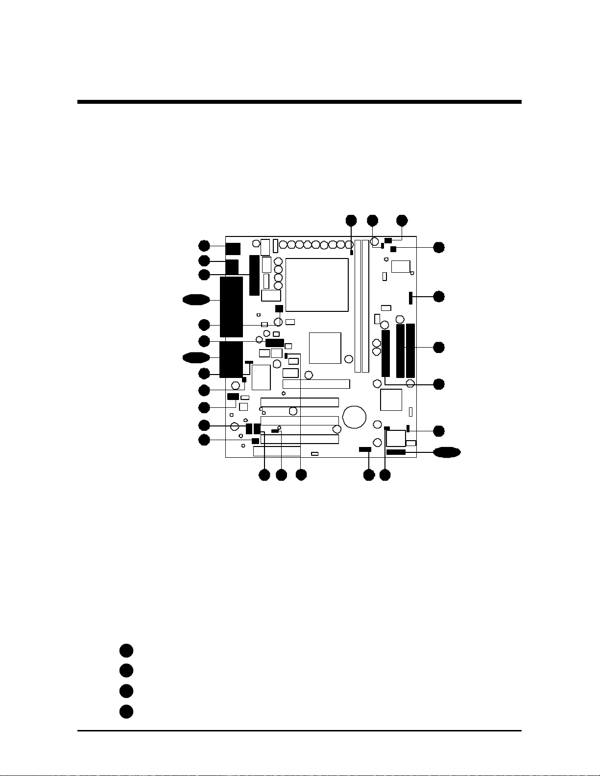
3 HARDWARE INSTALLATION
Before removing or installing any of these devices including CPU, DIMMs, Add-On
Cards, Cables, please make sure to unplug the onboard power connector.
This section outlines how to install and configure your ME21 mainboard. Refer to the
following mainboard layout to help you to identify various jumpers, connectors, slots, and
ports. Then follow these steps designed to guide you through a quick and correct installation of your system.
3.1 Step-by-Step Installation
Accessories of ME21
FAN2
PGA370
FAN2
1
1
1
JP3
1
JP5
J1
CA5657A ES
9952
9250AF-30
J17
IDE2
FLP1
1
IDE1
IR Connector-J17
FSB Speed Config. Setting - J1,JP3,JP5
PS/2 Keyboard/Mouse
Connectors
ATX Power Connector
Two USB Connectors
Serial Port
Connector (COM1)
Parallel Connector
FAN1
SOCKET 370
Connector - JP9 COM2
VGA Connector
Clear Password - J7
Line-In/Line-Out/Mic-In
Game/MIDI Connectors
Wake on modem - JP10
KBMS1
USB
JP8
PRN
1
Two DIMM Sockets
JWR1
RichTek
RT9231
CS1M91
FAN1
1
JP9
JP10
1
J7
Chassic intrusion - J9
I/O Controller
On Board Audio_IN CODEC
Onboard Audio
Connectors
FAN3
CNR Slot
J9
1
AJ1
1
JP13
FAN3
1
ME21
Wake on LAN - J13
CNR1
1 1
Two E-IDE Connectors
J5
J23
1
1
1
KEYLOCKPWR LED
IDE LEDRST EPMIGLED POW BTN
J2
SPKR
DIMM1
inbond
AM. MEGA. 87-96
W83627HF-AW
c
1
J13
JP12
1
DIMM2
J6
1
1
Floppy Connector
Programmable Flash EEPROM
Clear CMOS - J2
Front Panel Connector - J23
Three PCI Slots
One AGP Slot
2 USB ports header - J6
FWH boot block lock - J5
- 12 -
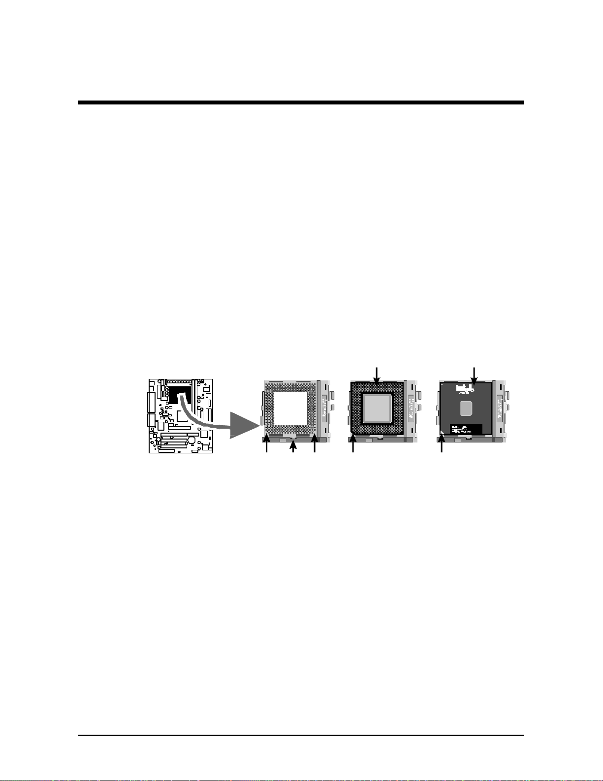
Step 1
Install the CPU:
1. Locate the CPU ZIF (Zero Insertion Force) socket on the upper-right
sector of your mainboard (between the back-panel connectors and the
DIMM memory banks).
2. Pull the CPU ZIF socket lever slightly sideways away from the socket
to unlock the lever, then bring it to an upward vertical position.
3. Place your PPGA / FC-PGA 370 processor in the ZIF socket. Note that
the CPU’s edges have been purposely designed non-symmetrical to
prevent from inserting the processor in the wrong direction. The following diagram demonstrates the correct placement of the CPU in the ZIF
socket. You can see that the two blunt-edged corners should face towards the socket-lever.
PPGA CPU FC-PGA CPU
BlankBlank Lever
Notch
Notch
4. Slightly push the CPU into the socket without applying excessive force
while making sure there is no gap between CPU and socket. Then lower
the socket-lever all the way down to its horizontal position and lock it to
secure the CPU in place.
5. The PPGA / FC-PGA 370 CPU requires a set of heatsink/fan to ensure
proper cooling of the processor. If they are not already mounted on your
CPU,you must purchase them separately and have it installed. Plug the
cable from the heatsink/fan to the CPU fan power connector located
nearby. Note that there are several types of CPU fan connectors. Normally,
if your mainboard supports the hardware monitoring function, a 3-pin fan
power connector should allow your system to detect the CPU fan’s speed .
The CPU fan can also run with a 2-pin fan power connector, however,
detection of CPU fan’s speed is not supported. Another type of CPU fan
may feature a large 4-pin fan power connector, which does not support
CPU fan's speed detection and must connect directly to the system’s
power supply unit.
- 13 -

Step 2.
Set Jumpers
This mainboard is jumperless! The default jumper settings have been set for
the common usage standard of this mainboard. Therefore, you do not need
to reset the jumpers unless you require special adjustments as any of the
following cases:
1. Over-clock your CPU
2. Disabled the onboard audio before installing an add-on sound card
3. Clear CMOS
4. Clear system password
5. Clear PS/2 Keyboard Power on password
For first-time DIY system builders, we recommend that you do not change the
default jumper settings if you are not totally familiar with the mainboard
configuration procedures. The factory-set default settings are tuned for optimum system performance. For the advanced users who wish to customize
their system, section 3.2 Jumper Settings will provide detailed information on
how to configure your mainboard manually.
Step 3
Install SDRAM System Memory
To install memory, insert SDRAM memory module(s) in any one or two
DIMM banks. Note that SDRAM modules are directional and will not go in
the DIMM slots if they are not properly oriented. After the module is fully
inserted into the DIMM socket, lift the clips of both sides of the DIMM bank to
lock the module in place.
- 14 -

Step 4
Install Internal Peripherals in System Case
Before you install and connect the mainboard into your system case, we
recommend that you first assemble all the internal peripheral devices into the
computer housing, including ,but not limited to the hard disk drive (IDE/
HDD), floppy disk drive (FDD), CD-ROM drive, and ATX power supply unit.
This will greatly facilitate in making the connections to the mainboard described below.
To install IDE & FDD drives, follow this procedure:
1. Set the required jumpers on each device according to the instructions
provided by the manufacturer. (IDE devices, HDD and CD-ROM, have to
set jumpers to Master or Slave mode depending on whether you install
more than one device of each kind.)
2. Connect IDE cable and FDD cable on the back-panel of the internal
peripheral devices to the corresponding headers on board. Note that the
cable should be oriented with its colored stripe (usually red or magenta)
connected to pin#1 both on the mainboard IDE or FDD connector and on
the device as well.
3. Connect an available power cable from your system power supply unit
to the back-panel of each peripheral device. Note that the power cable is
directional and cannot fit in if not properly positioned.
- 15 -
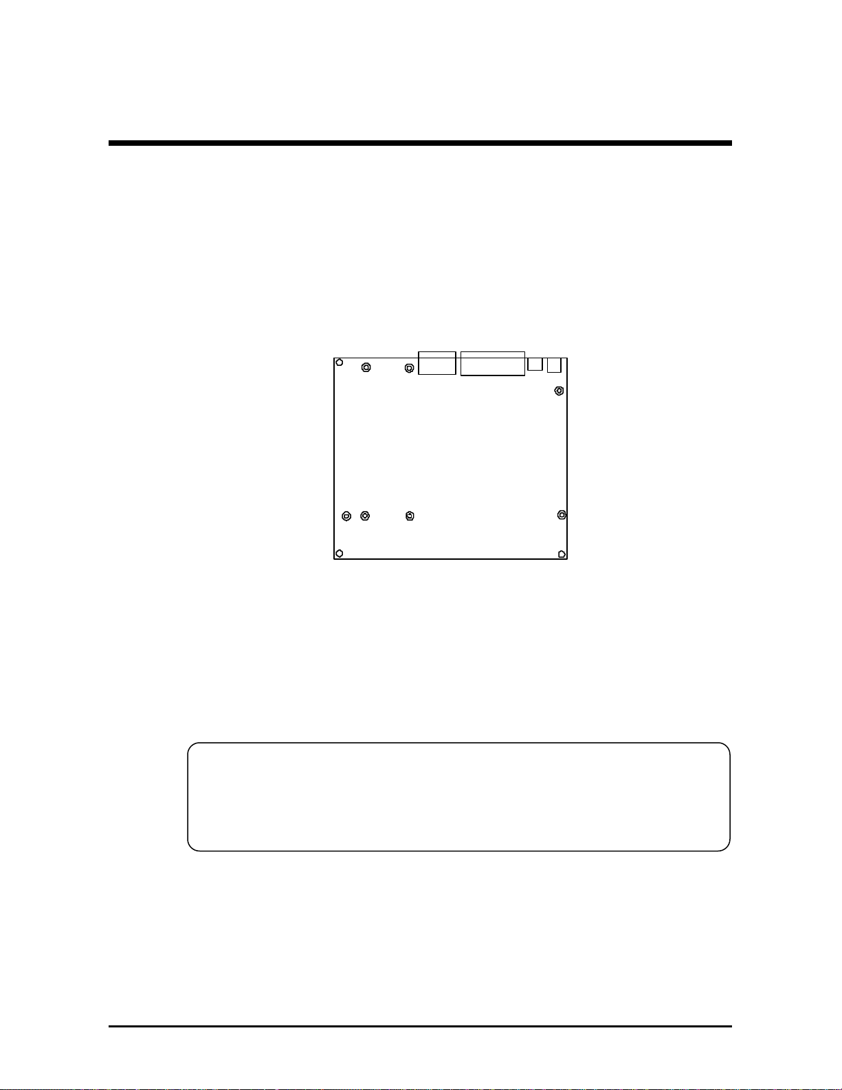
Step 5
Mount the Mainboard on the Computer Chassis
1. You may find that there are a lot of different mounting hole positions
both on your computer chassis and on the mainboard. To choose
correct mounting holes, the key point is to keep the back-panel of the
mainboard in a close fit with your system case, as shown below.
2. After deciding on the proper mounting holes, position the studs between
the frame of the chassis and the mainboard. The studs are used to fix the
mainboard and to keep a certain distance between the system chassis
and the mainboard, in order to avoid any electrical shorts between the
board and the metal frame of the chassis. (If your computer case is
already equipped with mounting studs, you will need to tighten screws to
attach the mainboard.)
Note: In most computer housings, you will be able to find 4 or more
attachment points to install mounting studs and then fix the
mainboard. If there aren’t enough matching holes, then make sure to
install at least 3 mounting studs to ensure proper attachment of the
mainboard.
- 16 -

Step 6
Connect Front Panel Switched/LEDs/Speaker
You can find there are several different cables already existing in the system
case and originating from the computer’s front-panel devices (HDD LED,
Power LED, Reset Switch, PC Speaker, etc.) These cables serve to connect
the front-panel switches and LEDs to the mainboard’s front-panel connectors
group. Following are the pin assignments and the connectors group:
PWR LED
J23
1
KEYLOCK SPKR
RST IDE
LED
GLED EPMI POW
BTN
1. HDD LED (IDE LED)
2. RESET (RST)
- Hardware Reset Switch
3. Green LED (GLED)
- 17 -
J23
J23
J23
PWR LED
KEYLOCK SPKR
+
1
RST
PWR LED
+
1
RST
PWR LED
+
1
RST
+
+
IDE LED GLED
KEYLOCK SPKR
+
+
IDE LED GLED
KEYLOCK SPKR
+
+
IDE LED GLED
EPMI
EPMI
EPMI
POW BTN
POW BTN
POW BTN

4. Power Switch (POW BTN)
- ATX Soft Power On/Off
J23
PWR LED
KEYLOCK SPKR
+
1
RST
+
+
IDE LED GLED
EPMI
POW BTN
5. SPEAKER (SPKR)
6. POWER LED (PWR LED)
7. KEYLOCK
J23
J23
J23
PWR LED
KEYLOCK SPKR
+
1
RST
PWR LED
+
1
RST
PWR LED
+
+
+
IDE LED GLED
KEYLOCK SPKR
+
+
IDE LED GLED
KEYLOCK SPKR
EPMI
EPMI
POW BTN
POW BTN
8. EPMI (Hardware System
Management Interface)
- 18 -
J23
1
RST
PWR LED
+
1
RST
+
+
IDE LED GLED EPMI POW BTN
KEYLOCK SPKR
+
+
IDE LED GLED EPMI POW BTN

Step 7
Connect IDE & Floppy Disk Drives
1. IDE cable connector
2. FDD cable connector
IDE1IDE2
FDC 1
- 19 -

Step 8
Connect Other Internal Peripherals
1. COM 2 cable connector
2. Audio Connector :
Telephone-IN(JP11),
Auxiliary CD_IN(JP12),
CD_IN(JP13) Connector.
Step 9
Connect the Power Supply
1. System power connector
JP9
JP11
1
JP13 JP12
1
1
1
- 20 -
FWR1

Step 10
Install Add-on Cards in Expansion Slots
1. Accelerated Graphics Port (AGP) Card
2. AIMM Card
(AGP In_Line Memory Module)
This slot can support AIMM for up
to 4MB of 133MHz SDRAM
display cache to deliver high
quality video graphics.
Note: The AIMM Card is optional
at the time of purchase.
3. PCI Card
4. CNR(Communication Network Riser) Card
The CNR Slot supports the
audio, modem, lan, Home PNA
of the Intel 815E chipset.
Note: The CNR Card is optional
at the time of purchase.
- 21 -

Step 11
Connect External Peripherals to Back Panel
You are now ready to put the computer case back together and get on to the
external peripherals connections to your system’s back-panel.
KB MS1
USB
JP 8
1. PS/2 Mouse and Keyboard
PS/2 Mouse
2. USB Devices
3. COM Port
PS/2 keyboard
USB1 & USB2
COM1
- 22 -

4. VGA Port
5. Parallel Port
6. MIDI/GAME Port
VGA
Parallel Port
MIDI/GAME Port
7. Audio Line-in / Line-out / Mic-in
Line-Out Mic-InLine-In
- 23 -

Step 12
First Time System Boot-Up
To assure the completness and correctness of your system installation, you
may check the above installation steps once again before you boot up your
system for the first time.
1. Insert a bootable system floppy disk (DOS 6.2x, Windows 95/98/NT, or
others) which contains FDISK and FORMAT utilities into the FDD.
2. Turn on the system power.
3. First, you must use the FDISK utility to create a primary partition of the
hard disk. You can also add an extended partition if your primary partition does not use all of the available hard disk space. If you choose to
add an extended partition, you will have to create one or more logical
partitions to occupy all the space available to the extended partition. The
FDISK utility will assign a drive letter (i.e., C:, D:, E:,...) to each partition
which will be shown in the FDISK program. After FDISK procedure,
reboot your system by using the same system floppy disk.
Note: DOS 6.2x and Windows 95A can only support up to 2.1GB of
HDD partition. If you use the FDISK utility with one of the operating systems mentioned above, you can only divide your HDD into
partitions no larger than 2.1GB each.
4. Now, use the FORMAT utility to format all the partitions you’ve created.
When formatting the primary partition (C:), make sure to use the FORMAT C: /S command.
Note: FORMAT C: /S can transfer all the necessary system files into the
primary partition of your hard disk. Then, your HDD will become
a bootable drive.
5. Install all the necessary drivers for CD-ROM, Mouse, etc.
6. Setup the complete operating system according to your OS installation
guide.
- 24 -

Step 13
Install Drivers & Software Components
Please note that all the system utilities and drivers are designed for Win 9x
operating systems only. Make sure your Windows 9x operating system is
already installed before running the drivers installation CD-ROM programs.
1. Insert the ME21 bundled CD-ROM into your CD-ROM drive. The
auto-run program will display the drivers main installation window on
screen.
2. Select the "Install Mainboard Software" bar in the sub-menu.
3. Choose "Install Chipset System Driver" and complete it.
4. Choose "Install AC97 Audio Driver" and complete it.
5. Choose "Install AGP Device Software" and complete it.
6. Return to the main installation window and exit from the auto-run drivers
installation program.
- 25 -

3.2 Jumper Settings
Several hardware settings are made through the use of jumper caps to connect jumper pins on the mainboard. Pin #1 could be located at any corner
of each jumper, you just find a white right angle on the mainboard, that's pin
1#. There are several types of pin 1# shown as below:
3-pin and multi (>3) pin jumpers shown as following:
Pin #1 on the left:
Pin #1 on the top:
Pin #1 on the right:
Pin #1 on the bottom:
Jumpers with two pins are shown as for Close [On] or for
Open [Off]. To Short jumper pins, simply place a plastic jumper cap over the
desired pair of pins.
Caution!
1. Do not remove the mainboard from its antistatic protective packaging
until you are ready to install it.
2. Carefully hold the mainboard by its edges and avoid touching its
components. When putting the mainboard down, place it on top of its
original packaging film, on an even surface, and components side up.
3. Wear an antistatic wrist strap or take other suitable measures to prevent
electrostatic discharge (ESD) whenever handling this equipment.
- 26 -
Jumpers & Connectors Guide
Use the mainboard layout on page 12 to locate CPU socket, memory banks,
expansion slots, jumpers and connectors on the mainboard during the installation. The following list will help you to identify jumpers, slots, and connectors along with their assigned functions:
E2
B3~B5
E2
B6~B9
B1
B2
E1
E2
E3
A1
E5
E6
E6
E2
A4 A4 E2
E2
E2
E2
E2
E2
E2
E2
E2
E2
E2
E2
E2
A4
E9
E2
E9
E2
D1
E2
D1
E2
A2
C1~C8
E2
E4
E7E6
E2E2E2E2E2
A3E8
CPU/Memory/Expansion Slots
Socket370 : CPU Socket for PPGA/FC-PGA 370 processors
DIM1/2 : Two DIMM Sockets for 16,32,64,128,256,512MB
,3.3V SDRAM(Max of total is 512MB)
AGP / AIMM: One AGP (Accelerated Graphics Port) Slot / AGP In_Line
Memory Module
PCI : Three 32-bit PCI Expansion Slots
CNR : Communication Network Riser Card
Jumpers
J7 : Clear PS/2 Keyboard power on password
A1
A2
J2 : Clear CMOS setting
J5 : Firmware Hub block lock
A3
J1,JP3,JP5 : FSB speed auto configure setting
A4
- 27 -

Back Panel Connectors
KB : PS/2 Keyboard
B1
B1
MS : PS/2 Mouse
B2
USB : 2 × USB (Universal Serial Bus) Ports
B3
COM1 : Serial Port 1 (DB9 male)
B4
VGA : VGA Port (DB15 female)
PRINTER : Parallel Port (DB25 female)
B5
LINE_OUT : LINE_OUT Port
B6
LINE_IN : LINE_IN Port
B7
MIC_IN : MIC_IN Port
B8
GAME/MIDI : GAME/MIDI Port
B9
Front Panel Connectors
C1
C2
C3
C4
RESET : Hardware Reset Switch
HDD LED : IDE Drive Active LED
KEYLOCK : KEYLOCK
EPMI : Hardware System Management Interface Momentary
Type Switch
Power Switch : ATX Power On/Off Momentary Type Switch
C5
Power LED : System Power LED
C6
Green LED : Green LED
C7
SPEAKER : Housing Internal Speaker
C8
Internal Peripherals Connectors
FLP1 : Floppy Disk Drive Interface
D1
IDE1 : IDE Primary Interface (Dual-channel)
D1
IDE2 : IDE Secondary Interface (Dual-channel)
D1
Other Connectors
E1
E2
E2
E2
E3
E4
E5
JWR1 : ATX Power (20-pin header) Connector
FAN1 : CPU FAN Connector
FAN2 : System FAN Connector
FAN3 : AGP FAN Connector
JP9 : COM2 Connector
JP10 : Wake On Modem Connector
J9 : Chassis Intrusion Connector
E6
E6
JP11 : Telephone_IN Connector
J12 : Auxiliary_IN Connector
- 28 -

E6
E7
JP13 : CD_IN Connector
J13 : Wake on Lan Connector
E8
E9
J6 : Front Panel USB Header
J17 : IR Connector
- 29 -

Clear PS/2 Keyboard Power on Password (J7)
A1
J7 is used to clear PS/2 keyboard power on password. Clearing the J7 will
result in erasing the password you set and then user may power on your
system without any secret code.
Pin 2-3 (Clear Password)
Pin 1-2 (Default)
Step 1. Turn off the system power (PC-> Off)
Step 2. Remove jumper cap from pin 1-2 on J7
Step 3. Place the jumper cap on pin 2-3 on J7 for a few seconds
Step 4. Return the jumper cap to pin 1-2
Step 5. Turn on the system power (PC-> On)
A2
Clear CMOS Setting (J2)
J2 is used to clear CMOS data. Clearing CMOS will result in permanently
erasing the previous system configuration settings and restoring the original
(factory-set) system settings.
Pin 1-2 (Default)
1
J7
Pin 2-3 (Clear CMOS)
Step 1. Turn off the system power (PC-> Off)
Step 2. Remove jumper cap from J2 pins 1-2
Step 3. Place the jumper cap on J2 pin 2-3
for a few seconds
Step 4. Return the jumper cap to pin 1-2
Step 5. Turn on the system power (PC-> On)
- 30 -
J2
1

Firmware Hub Block Lock (J5)
1
1
A3
Placing jumper cap on Pin 1-2 allows you to flash your BIOS(FWH).
(Default)
(Flash BIOS)
Step 1. Turn off the system power (PC-> Off)
Step 2. Place jumper cap over pin 1-2 on J5 and then turn on your system to
execute flash utility.
J5
1
- 31 -

A4
1
1
FSB Speed Auto Configure Setting (J1, JP3, JP5)
ME21 provides jumper JP3 and JP5 to set auto configure front side bus at
66MHz, 100MHz, 133MHz. Insert mini-jumper caps on JP3 and JP5 and
leave J1 all open as below to identify automatically the FSB speed.
Default
JP3 JP5
J1
1
1-2
3-4
System Clock JP3 JP5 J1 (1-2) J1 (3-4)
Auto ON ON OFF OFF
66 MHz OFF OFF ON ON
100 MHz OFF OFF ON OFF
JP5
JP3
1
1
J1
1
133 MHz OFF OFF OFF OFF
- 32 -

B1
PS/2 Keyboard & PS/2 Mouse Connectors
Two 6-pin female PS/2 keyboard & Mouse
connectors are located at the rear panel of
the mainboard. Depending on the computer
housing you use (desktop or minitower), the
PS/2 Mouse connector is situated at the top
of the PS/2 Keyboard connector when the
mainboard is laid into a desktop, as opposed
to a minitower where the PS/2 Mouse connector is located at the right of the PS/2
Keyboard's. Plug the PS/2 keyboard and
mouse jacks into their corresponding connectors.
P.S.: If user plug PS/2 keyboard or PS/2 mouse in the wrong PS/2 connec-
tor, AMI BIOS will switch both of them.
B2
USB1/USB2 Port Connectors
This mainboard offers 2 USB ports on front
panel. Plug each USB device jack into an
available USB1/USB2 connector.
PS/2 Mouse
PS/2 keyboard
B3
COM1 Connector
This mainboard can accommodate one serial device on COM1. Attach a serial device
cable to the DB9 serial port COM1 at the back
panel of your computer.
B4
VGA Connector
One 15-pin VGA connector is located at the
rear panel of the mainboard.
B5
Parallel Port Connector
One DB25 female parallel connector is located at the rear panel of the mainboard.
Plug the connection cable from your parallel device (printer, scanner, etc.) into this connector.
USB1 & USB2
COM1
VGA
Parallel Port
- 33 -

B6
Line-Out
B7
Line-In
B8
Mic-In
Line-Out is a stereo output port through which
the combined signal of all internal and external audio sources on the board is output. It
can be connected to 1/8-inch TRS stereo
headphones or to amplified speakers
Line-In is a stereo line-level input port that
accepts a 1/8-inch TRS stereo plug. It can be
used as a source for digital sound recording,
a source to be mixed with the output, or both.
Mic-In is a 1/8-inch jack that provides a mono
input. It can use a dynamic mono or stereo
microphone with a resistance of not more than
600 Ohms.
Line-Out
Line-In
Mic-in
B9
MIDI/GAME Port
The MIDI/GAME port is a 15-pin female connector. This port can be connected to any
IBM PC compatible game with a 15-pin Dsub connector.
MIDI Instrument Connection
You will need a MIDI adapter to connect a MIDI compatible instrument
to the sound card. The MIDI adapter can in turn be connected to the
Joystick/MIDI port. You will also need the MIDI sequencing software to
run MIDI instruments with your computer etc.) into this connector.
MIDI/GAME Port
- 34 -

C1
Hardware Reset Connector (RST)
Attach the 2-pin hardware reset switch cable to the RST header. Pressing
the reset switch causes the system to restart.
J23
+
PWR LED
KEYLOCK SPKR
C2
HDD LED Connector (IDE LED)
Attach the connector cable from the IDE device LED to the 2-in HDD LED
header. The HDD LED lights up whenever an IDE device is active.
C3
Keylock Connector (KEYLOCK)
Attach the 2-pin KEYLOCK connector cable from the housing front panel
to the KEYLOCK header on the mainboard.
1
J23
1
RST IDE
PWR LED
+
RST IDE
+
+
GLED EPMI POW
LED
KEYLOCK SPKR
+
+
GLED EPMI POW
LED
BTN
BTN
J23
- 35 -
1
PWR LED
+
RST IDE
KEYLOCK SPKR
+
+
GLED EPMI POW
LED
BTN

C4
EPMI
Hardware System Management Interface (EPMI) header may attach to a
2-pin momentary switch. Press the EPMI switch to force the system into
power saving mode; press again to resume normal operation.
PWR LED
J23
+
KEYLOCK SPKR
1
RST IDE
ATX Power On/Off Switch Connector (POW BTN)
C5
+
+
LED
GLED EPMI POW
The Power On/Off Switch is a momentary type switch used for turning on
or off the system’s ATX power supply. Attach the connector cable from
the Power Switch to the 2-pin POW BTN header on the mainboard.
PWR LED
KEYLOCK SPKR
+
RST IDE
LED
+
GLED EPMI POW
C6
Power LED Connector(PWR LED)
J23
+
1
BTN
BTN
Attach the 3-pin Power-LED connector cable from the housing front panel
to the PWR LED header on the mainboard. The power LED stays light
while the system is running.
PWR LED
J23
1
+
RST IDE
+
KEYLOCK
LED
+
GLED EPMI POW
SPKR
BTN
- 36 -

Green LED Connector (GLED )
C7
The Green LED (GLED) indicates that the system is currently in one of the
power savings mode (Doze/Standby/Suspend). When the system resumes
to normal operation mode, the Green LED will go off. Attach a 2-pin
Green LED cable to GLED header.
J23
+
PWR LED
KEYLOCK SPKR
Note : Please notice all the LED connector is directional. If your chassis’s
LED does not light during running, please simply change to the
opposite direction.
C8
Speaker Connector (SPKR)
Attach the PC speaker cable from the case to the 4-pin speaker connector
(SPKR).
J23
1
1
RST IDE
PWR LED
+
RST IDE
+
+
GLED EPMI POW
LED
KEYLOCK SPKR
+
+
GLED EPMI POW
LED
BTN
BTN
C2
- 37 -

Enhanced IDE Connector and Floppy Connector
D1
The ME21 mainboard features two 40-pin dual-channel IDE device connectors (IDE1/IDE2) providing support for up to four IDE devices, such as CDROM and Hard Disk Drives (H.D.D.). This mainboard also includes one 34pin floppy disk controller (FDC) to accommodate the Floppy Disk Drive
(F.D.D.). Moreover, this mainboard comes with one 40-pin ATA33 ( or
optional ATA/66 or ATA/100 ) ribbon cable to connect to IDE H.D.D. and
one 34-pin ribbon cable for F.D.D. connection.
IDE1IDE2
FDC 1
Note : Please connect your system H.D.D. to IDE 1.
Important : Ribbon cables are directional, therefore, make sure to
always connect with the red cable
- 38 -

E1
ATX Power Supply Connector (JWR1)
Locate the 20-pin male header ATX power connector (JWR1) on your
mainboard. Plug the power cable from the ATX power supply unit directly
into JWR1 ATX power supply connector.
Note 1: The ATX power connector is directional and will not go in
unless the guides match perfectly making sure that pin#1 is
properly positioned.
Note 2: Make sure the latch of the ATX power connector clicks into place
to ensure a solid attachment.
Note 3: Your ATX power supply must be supplied to ACPI +5V standby
power and at least 720mA compatible.
JWR1
Note 4: Make sure your power supply have enough power for higher
speed processor installed.
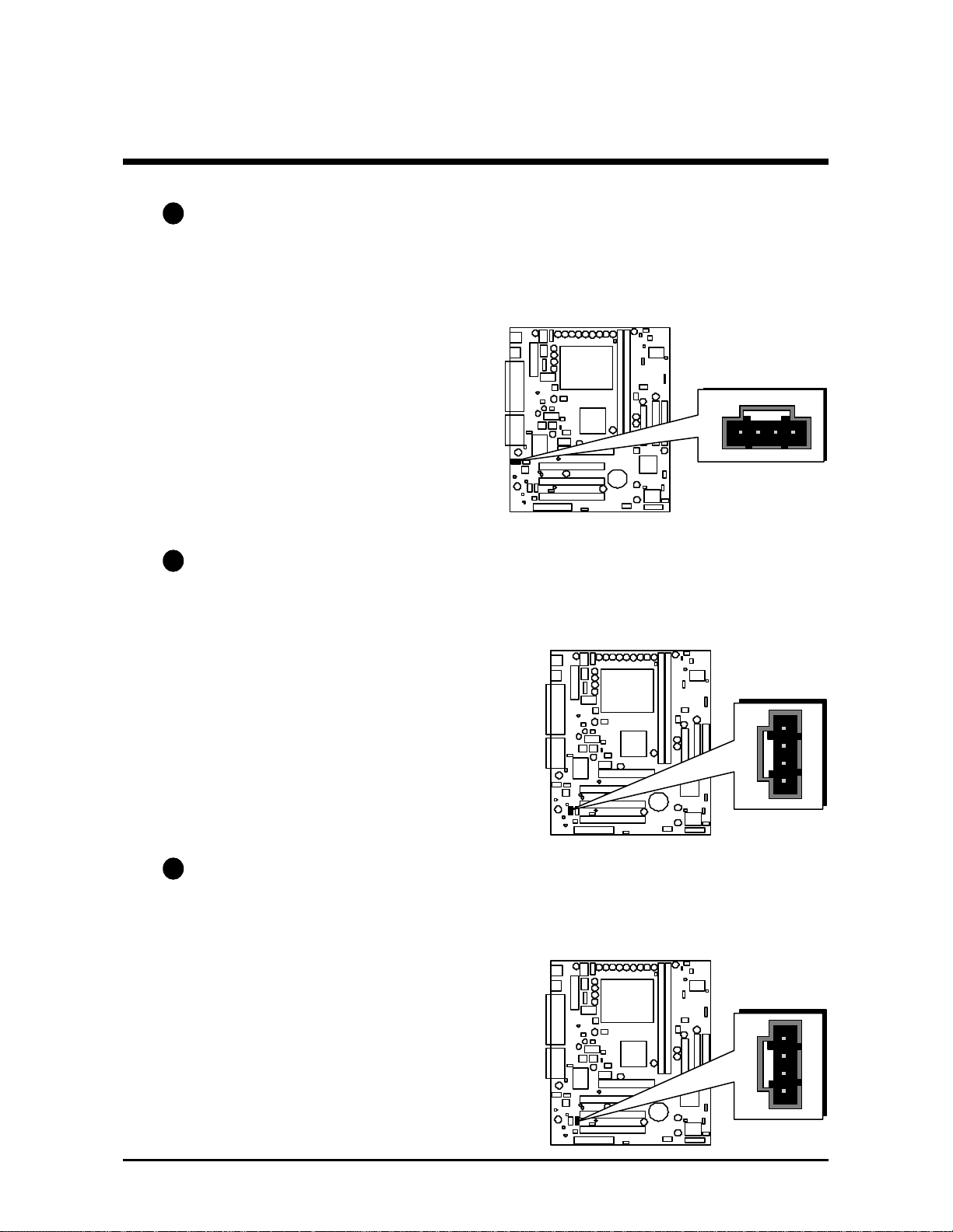
E2
CPU, System, AGP Fan connectors - FAN1, FAN2, FAN3
The mainboard provides three onboard 12V cooling fan power connectors
to support CPU (FAN1), System (FAN2), and AGP (FAN3) cooling fans.
Note:
FAN1
1
Both cable wiring and type of
plug may vary depending on
the fan maker. Keep in mind
that the red wire should always
be connected to the +12V
header and the black wire to the
ground (GND) header.
FAN2
1
FAN3
1
- 39 -
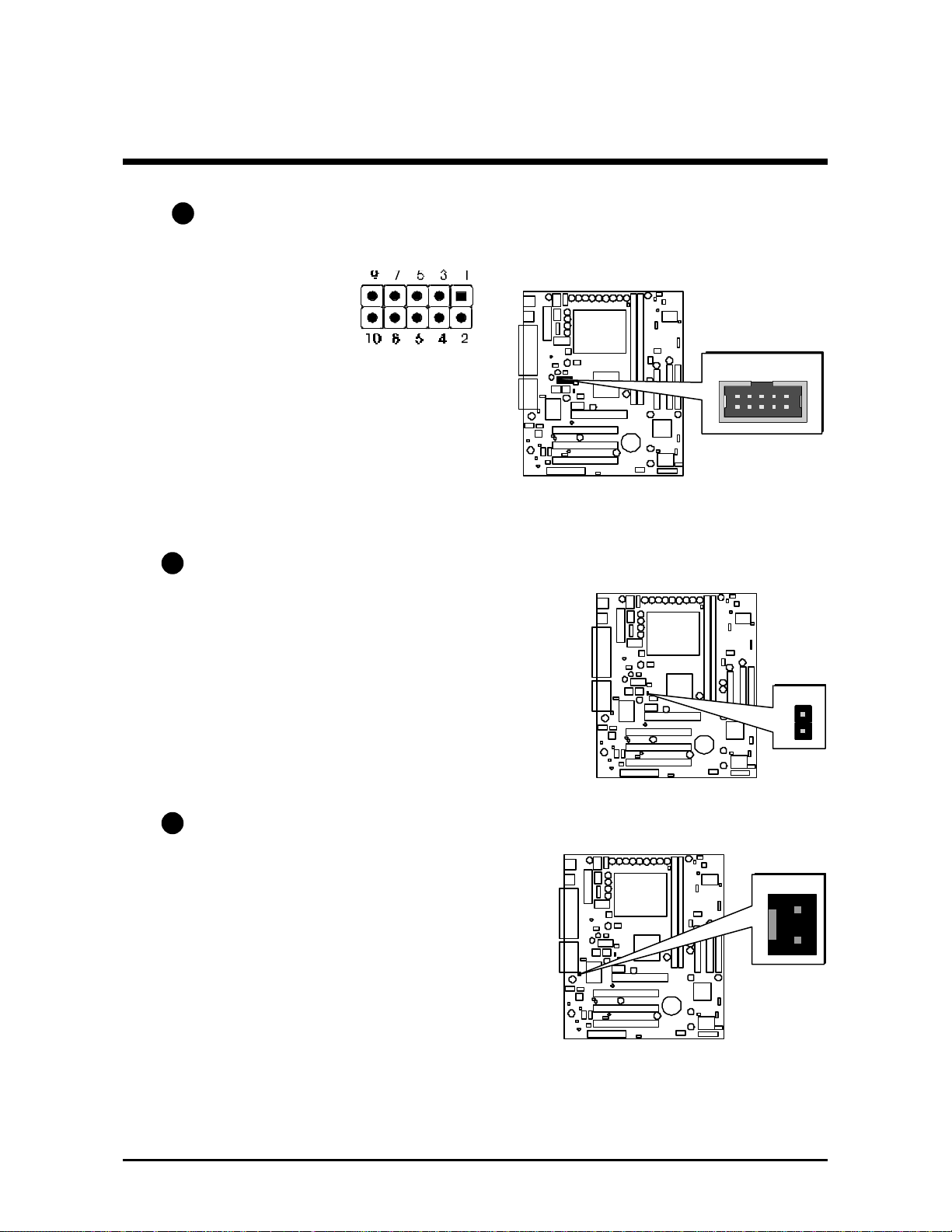
E3
COM2 Connector (JP9)
This mainboard comes with one 10-pin ribbon cable for COM2.
Pin Assignments:
1=DCD2 2=DSR2
3=RX2 4=RTS2
5=TX2 6=CTS2
7=DTR2 8=RI2
9=GND 10=KEY
E4
Wake-on Modem Connector (JP10)
Attach a 2-pin connector from the Modem
which supports the Wake-On Modem
function. This function lets users ring in the
connected system through the Modem.
JP 9
1
JP 10
1
E5
Chassis Intrusion (J9)
Joint this 2-pin connector with chassis
cover. This function activate detection any
intrusion into the chassis.
1 J9
- 40 -
E6
Audio Telephone_IN Header (JP11)(Green)
Port JP11 can be used to connector a modem audio line to ME21
mainboard. Typically, you would use this connector when running the
voice mail software on your system for audio input and output.
Pin Assignments:
1=MONO_PHONE
2=AGND
3=AGND
4=MONO_OUT
E6
Audio CD_IN Header (JP13)(Black)
Port JP13 is used to attach an audio connector cable from the CD-ROM
drive.
Pin Assignments:
1=CD-L
2=CD-GND
3=CD-GND
4=CD-R
JP11
1
JP13 1J12
E6
Audio AUXILIARY_IN Header (J12)(White)
Port J12 can be used to connect a stereo audio input from such as CDROM, TV-tuner or MPEG card.
Pin Assignments:
1=AUXL
2=AGND
3=AGND
4=AUXR
- 41 -
1

Wake on Lan (J13)
E7
Attach a 3-pin connector from the LAN card which supports the Wake-OnLAN (WOL) function. This function lets users wake up the connected system
through the LAN card.
E8
Optional two ports USB Header (J6)
This header is used to connect the cable attached to optional USB connectors which support another two USB ports.
If the user needs the USB cable, please contact with the mainboard vender or
supplier.
Note: Either front panel USB1/USB2 port or the midboard two USB ports
header (J6) can be available at the same time.
Pin Assignments:
1
Data 1+
+5V
J13
1
GND
Data 1GND
GND
NC
Data 0+
Data 0-
J6
1
- 42 -

IR Connector(J17)
E9
If you have an Infrared device, this mainboard can implement IR transfer
function. To enable the IR transfer function, follow these steps:
IR Pin Assignments:
1=VCC
2=NC
3=IRRX
4=GND
5=IRTX
5
4
3
2
1
1
Note : Before connect your IR device, please be sure each IR on board pin
allocation is matchable with the pin of the IR device. Otherwise,
incorrect IR connection may do damage to your IR device.
Step 1. Attach the 5-pin infrared device cable to IR connector.
(Refer to the above diagram for IR pin assignment.)
Step 2. Configure the Infrared transfer mode in the Serial Port B Mode field
of Peripheral Setup menu of BIOS. This mainboard supports IrDA,
ASKIR, Normal transfer modes.
J17
- 43 -

3.3 System Memory Configuration
The ME21 mainboard has two 168-pin DIMM sockets that allow you to
install from 16MB up to 512MB of system memory with SDRAM (Synchronous DRAM). Each DIMM (Dual In-line Memory Module) socket can accommodate 16MB, 32MB, 64MB, 128MB, 256MB and 512MB 3.3V single or
double side SDRAM modules. DIMM sockets are arranged in two banks,
each memory bank made of one socket and providing a 64/72-bit wide data
path.(The total installed memory dose not exceed 512MB.)
1. Install Memory:
Install memory in any or all of the banks and in any combination, as follows.
DIMM
Socket
DIMM 1
DIMM 2
Memory Modules
16MB, 32MB, 64MB, 128MB, 256MB, and 512MB
168-pin 3.3V SDRAM DIMM
16MB, 32MB, 64MB, 128MB, 256MB, and 512MB
168-pin 3.3V SDRAM DIMM
Module
Quantity
x 1
x 1
Note: You do not need to set any jumper to configure memory since the
BIOS utility can detect the system memory automatically. You can
check the total system memory value in the Standard CMOS Setup
menu of BIOS SETUP.
2. Upgrade Memory:
You can easily upgrade the system memory by inserting additional SDRAM
modules in available DIMM banks. The total system memory is calculated by
simply adding up the memory in all DIMM banks. After upgrade, the new
system memory value will automatically be computed and displayed in the
Standard CMOS Setup menu of BIOS SETUP.
- 44 -

4 SOFTWARE UTILITY
4.1 ME21 Mainboard CD Overview
Note: The ME21 mainboard attached CD contents are subject to change
without notice.
To start your mainboard CD disc, just insert it into your CD-ROM drive and
the CD AutoRun screen should appear. If the AutoRun screen does not
appear, double click or run D:\Autorun.exe (assuming that your CD-ROM
drive is drive D:)
Navigation Bar Description:
F Install Mainboard Software
- Support user to install Chipset driver, IDE device driver, AGP device
software, onboard CODEC AC97 driver.
F Manual
- ME21 series mainboard user's manual in PDF format.
F Browse this CD
- Allows you to see the contents of this CD.
F Quit
- Close this CD.
- 45 -

4.2 Install Mainboard Software
Insert the attached CD into your CD-ROM drive and the CD AutoRun screen
should appear. If the AutoRun screen does not appear, double click on
Autorun icon in My Computer to bring up Shuttle Mainboard Software
Setup screen.
Select using your pointing device (e.g. mouse) on the “Install Mainboard
Software” bar to enter the sub-menu.
- 46 -

4.3 Install Chipset System Driver
Insert the attached CD into your CD-ROM drive and the CD AutoRun screen
should appear. If the AutoRun screen does not appear, double click on
Autorun icon in My Computer to bring up Mainboard Drivers & Utilities
screen.
Select using your pointing device (e.g. mouse) on the “Install Chipset System
Driver” bar.
Once you made your selection, a Setup window runs the installation automatically.
When the copying files is done, make sure you reboot the system to take the
installation effect.
Note: When the system reboots after the chipset system driver installing is
completed, it will continue the setup procedure and then reboot
automatically.
Note: When the Windows 95/98 reboot for the first time after Intel Chipset
System drivers installed, some new hardware devices will be found and
added. For those new hardware devices, related software drivers will be
searched for installing. The user may find the software drivers retain on the
directory C:\windows\system if some of software drivers could not be found
during searching.
- 47 -

4.4 Install IDE Driver
This driver may do bad effect on some model or brnad of IDE HDD devices.
Hereby, we won't suggest users to install it cause it might crash your HDD
data. However, if you are very sure that the driver matches your IDE HDD,
please follow below indication to complete the setup.
Insert the attached CD into your CD-ROM drive and the CD AutoRun screen
should appear. If the AutoRun screen does not appear, double click on
Autorun icon in My Computer to bring up Shuttle Mainboard Software
Setup screen.
Select using your pointing device (e.g. mouse) on the “Browse this CD ” bar.
And then find out the location: Mainbrd/Ultraata/cd to install the driver.
P.S.: Before doing this IDE Driver installation, setup Chipset System Driver is
necessary.
Once you made your selection, a Setup window runs the installation automatically.
When the copying files is done, make sure you reboot the system to take the
installation effect.
- 48 -

4.5 Install AC97 Audio Driver
Insert the attached CD into your CD-ROM drive and the CD AutoRun screen
should appear. If the AutoRun screen does not appear, double click on
Autorun icon in My Computer to bring up Mainboard Drivers & Utilities
screen.
Select using your pointing device (e.g. mouse) on the “Install AC97 Audio
Driver” bar.
Once you made your selection, a Setup window runs the installation automatically.
When the copying files is done, make sure you reboot the system to take the
installation effect.
- 49 -

4.6 Install AGP Device Software
Insert the attached CD into your CD-ROM drive and the CD AutoRun screen
should appear. If the AutoRun screen does not appear, double click on
Autorun icon in My Computer to bring up Mainboard Drivers & Utilities
screen.
Select using your pointing device (e.g. mouse) on the “Install AGP Device
Software” bar.
Once you made your selection, a Setup window runs the installation automatically.
When the copying files is done, make sure you reboot the system to take the
installation effect.
- 50 -

4.7 To View the User's Manual
Insert the attached CD into your CD-ROM drive and the CD AutoRun screen
should appear. If the AutoRun screen does not appear, double click on
AutoRun icon in My Computer to bring up Shuttle Mainboard Software
Setup screen.
Select using your pointing device (e.g. mouse) on the “Manual” bar.
Then the Online Information window will appear on your screen. Click on
the “Install Acrobe Reader 3.0” bar if you need to install acrobe reader.
Then click on "ME21 Manual" bar to view ME21 user's manual.
- 51 -

5 BIOS SETUP
ME21 BIOS ROM has a built-in Setup program that allows users to modify the
basic system configuration. This information is stored in battery-backed RAM so
that it retains the Setup information even if the system power is turned off.
The system BIOS is managing and executing a variety of hardware related
functions in the system, including:
System date and time
Hardware execution sequence
Power management functions
Allocation of system resources
5.1 Entering BIOS
To enter the BIOS (Basic Input / Output System) utility, follow these steps:
Step 1. Power on the computer and the system will perform its
POST (Power-On Self Test) routine checks.
Step 2. As you see the message "Hit F2 if you want to run setup.",
press <F2> key immediately.
Note : If you miss the train (the message disappears before you can
respond) and you still wish to enter BIOS Setup, restart the system
and try again by turning the computer OFF and ON again or by
pressing the <RESET> switch located at the computer’s front
panel. You may also reboot by simultaneously pressing the
<Ctrl>, <Alt>, <Del> keys.
Step 3. As you enter the BIOS program, the CMOS Setup Utility will
prompt you the Main Menu, as shown in the next section.
- 52 -

5.2 The Main Menu
Once you enter the AMIBIOS CMOS Setup Utility, the Main Menu will
appear on the screen. The Main Menu allows you to select from several
setup functions and two exit choices. Use the arrow keys to select among the
items and press <Enter> to accept and enter the sub-menu.
Please note that the function keys appear at the right bottom of screen.
Standard CMOS Setup
This setup page includes all items in a standard compatible BIOS.
Advanced CMOS Setup
This setup page includes all items of AMI special enhanced CMOS
features.
Advanced Chipset Setup
This setup page includes all items of chipset features.
Power Management Setup
This setup page includes all items of Power Management features.
PCI / Plug and Play setup
This item specifies the value (in units of PCI bus blocks) of the latency
timer for the PCI bus master and the IRQ level for PCI device. Power-on
with BIOS defaults.
- 53 -

Load Optimal Settings
Optimal settings load the values required by the System for the maximum performance. However, you can change the parameter through
each Setup Menu.
Load Fail Safe Settings
Fail Safe settings load the values required by the system for the O.K.
performance. However, you can change the parameter through each
Setup Menu.
Peripheral Setup
This setup page includes all items of peripheral features.
Hardware Monitor Setup
This setup page includes all items of hardware monitor features.
Change Supervisor Password
Change, set, or disable supervisor password. It allows you to limit
access to the system and Setup, or just to Setup.
Change User Password
Change, set, or disable user password. It allows you to limit access to
the system and Setup, or just to Setup.
Auto-Detect Hard Disks
This setup page can detect the hard disk automatically.
Save Settings & Exit
Save all the CMOS values changed to CMOS and exit setup
Exit Without Saving
Abandon all the CMOS values changed and exit setup.
- 54 -

@@ Standard CMOS Setup
The items in Standard CMOS Setup Menu are divided into several
categories. Each category includes no, one or more than one setup
items. Use the arrow key to highlight the item and then use the
<PgUp> or <PgDn> keys to select the value you want in each item.
Date
The date format is <month> <date> <year>.
Press <F3> to show the calendar.
Time
The time format is <hour> <minute> <second>. The time is
calculated base on the 24-hour military-time clock. For example. 5 p.m.
is 17:00:00.
Hard Disks Type
This item identify the types of hard disk drives that has been installed in
the computer. There are 46 predefined types and a user definable type.
Press PgUp or PgDn to select a numbered hard disk type or type the
number and press <Enter>. Note that the specifications of your drive
must match with the drive table. The hard disk will not work properly if
you enter improper information for this item. If your hard disk drive
type is not matched or listed, you can use Type User to define your
own drive type manually.
- 55 -

If you select Type User, related information is asked to be entered to the
following items. Enter the information directly from the keyboard and
press <Enter>. Those information should be provided in the documentation from your hard disk vender or the system manufacturer.
The user may also set those items AUTO to automatically configure
hard disk drives parameter when system is power-on.
If a hard disk drive has not been installed select NONE and press
<Enter>.
Drive A type/Drive B type
This item specifies the types of floppy disk drive A or drive B that has
been installed in the system.
Memory
This item is display-only. It is automatically detected by POST (Power
On Self Test) of the BIOS.
Base Memory
The POST of the BIOS will determine the amount of base (or conventional) memory installed in the system. The value of the base memory
is typically 512K for systems with 512K memory installed on the
mainboard, or 640K for systems with 640K or more memory installed
on the mainboard.
Extended Memory
The BIOS determines how much extended memory is present during
the POST. This is the amount of memory located above 1MB in the
CPU's memory address map.
- 56 -
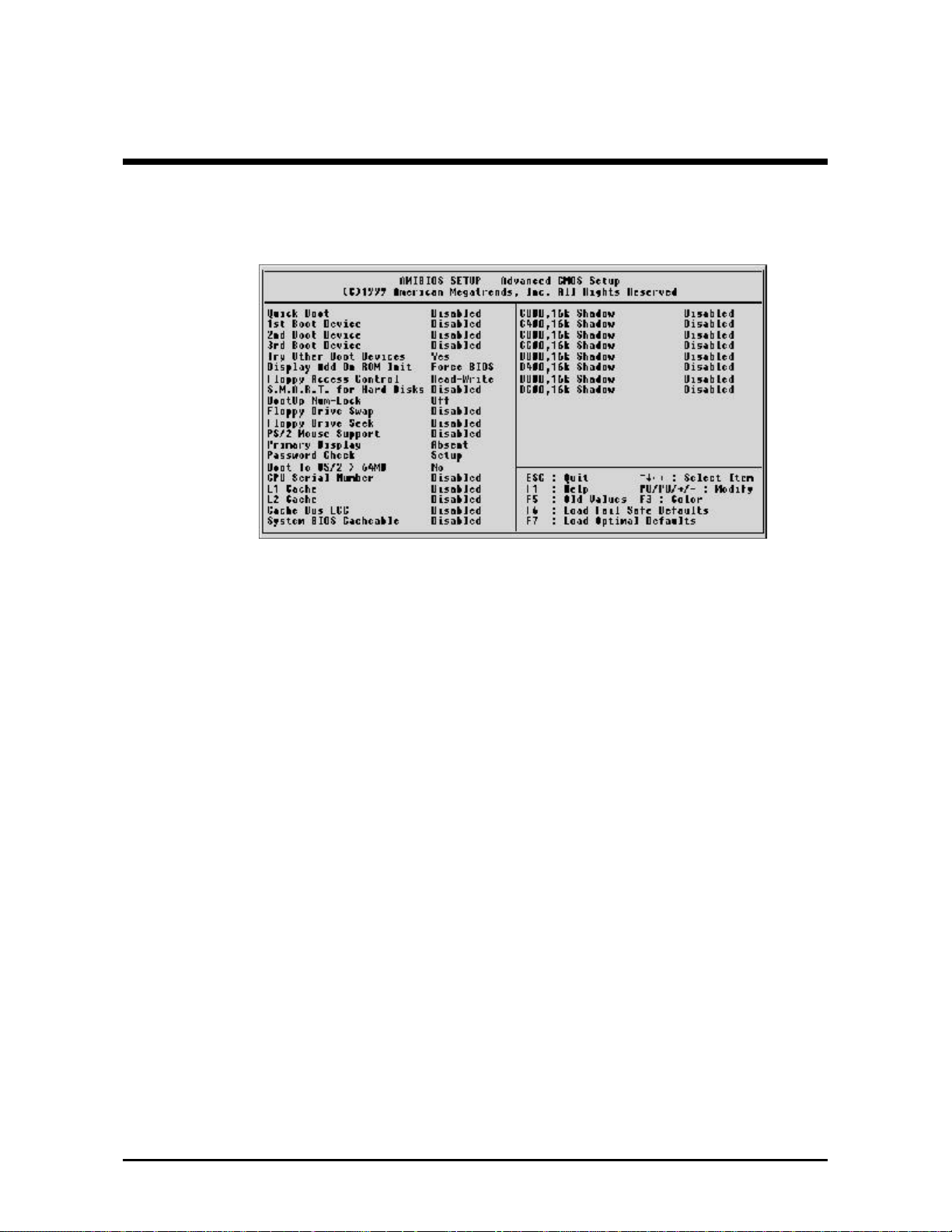
@@ Advanced CMOS Setup
Quick Boot
This item allows you to power on the computer without POST test.
1st/2nd/3rd Boot Device
This BIOS attempts to load the operating system from the devices in the
sequence selected in these items.
Ø The choice: Floppy, LS/ZIP, HDD-0, SCSI, CDROM, HDD-1, HDD-2,
HDD-3, LAN, Disabled.
Try Other Boot Devices
Select Your Boot Device Priority.
Ø The choice: Yes, No.
Display Mode at Add-On ROM Init
This option specifies the system display mode that is set at the time that
AMIBIOS POST initializes an optional option ROM.
Ø The choice: Force BIOS, Keep Current.
Floppy Access Control
This option specifies the read/write access that is set when booting from
a floppy drive.
Ø The choice: Read/Write or Read-Only
S.M.A.R.T. for Hard Disks
Set this option to Enabled to permit AMIBIOS to use the SMART (System
Management and Reporting Technologies) protocol for reporting server
system information over a network.
Ø The choice: Enable, Disable
- 57 -

BootUp Num-Lock
When this option enables, BIOS turns on Num Lock when system is
powered on.
Ø The choice: On / Off.
Flppy Drive Swap
When this item enables, the BIOS will swap floppy drive assignments so
that Drive A: will function as Drive B: and Drive B: as Drive A:.
Ø The choice: Enable, Disable
Flppy Drive Seek
During POST BIOS will determine if the installed floppy disk drive is 40
or 80 tracks.
Ø The choice: Enable, Disable
PS/2 Mouse Support
Set this option to Enabled to enable AMIBIOS support for a PS/2-type
mouse. Pins 2-3 of the PS/2 Mouse Selector jumper on the motherboard
must be shorted together to enable PS/2 mouse support.
Ø The choice: Enable, Disable
Primary Display
This option configures the type of monitor attached to the computer.
Ø The choice: Mono, CGA40x25, CGA80x25, VGA/EGA, or Absent.
Password Check
This item enables to check password at every booting time or when
running AMIBIOS setup.
Ø The choice: Always, Setup.
Boot To OS/2 >64MB
To set this option to Yes if running OS/2 operating system and using
more than 64 MB of system memory on the motherboard
Ø The choice: Yes, No.
CPU Serial Number
This item is for Pentium III Processor. During Enabled, this will check
the CPU Serial number. Disable this option if you don't want the system
to know the Serial number.
Ø The choice: Enable, Disable.
L1 Cache
This option enables the L1 internal cache memory.
Ø The choice: WriteBack, WriteThru, or Disabled.
- 58 -

L2 Cache
This option enables the L2 internal cache memory.
Ø The choice: WriteBack, WriteThru, or Disabled.
Cache Bus ECC
This option is for Pentium II/III processor. If you enable the function, this
will affect system performance.
System BIOS Cacheable
When set to Enabled, the contents of the F0000h system memory
segment can be read from or written to cache memory. The contents of
this memory segment are always copied from the BIOS ROM to system
RAM for faster execution.
Ø The choice: Enable, Disable
Cx00,16k Shadow / Dx00,16k Shadow
These options specify how the 64 KB of video ROM at C0000h is
treated. Also, the contents of Video ROM area from C0000h - C7FFFFh
can be written to or read from cache memory.
Ø The choice: Enable, Disable, Cache.
- 59 -
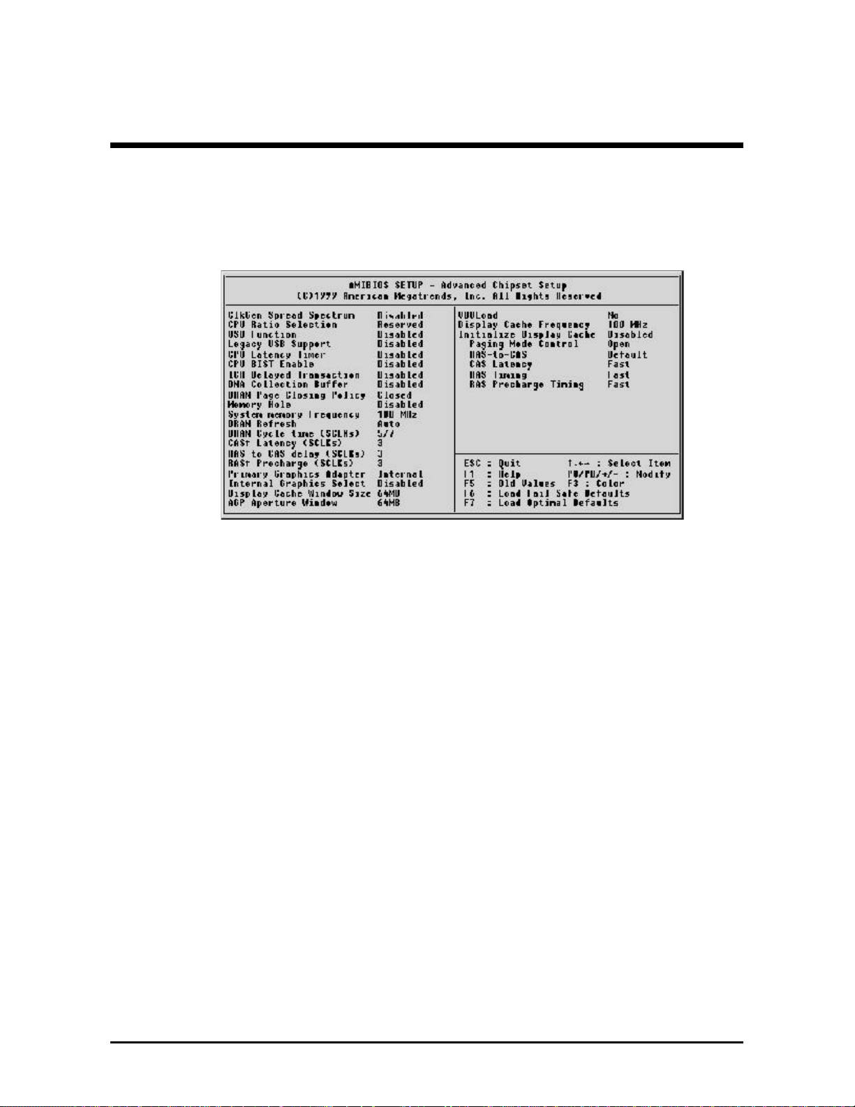
@@ Advanced Chipset Setup
ClkGEN Spread Spectrum (disable)
This item allows the user to enable Spread Spectrum modulated to
reduce EMI.
Ø The choice: Enable, Disable
CPU Ratio Selection
This item allows the user to set CPU ratio.
Note: If your CPU has frequency multiple locked, then this item is not
functional.
Ø The choice: X2.0(Safe), X2.5 ~ X8.0.
USB Function
Set this option to enable USB (Universal Serial Bus) support.
Ø The choice: Enable, Disable.
Legacy USB Support
Set this option to Enable or Disable USB keyboard/mouse legacy
support.
Ø The choice: Enable, Disable.
CPU Latency Timer
The CPU cycle is only deferred immediately after receiving another
ADS# signal.
Ø The choice: Enable, Disable.
- 60 -

CPU Bist Enable
Set this option to enable CPU BIST.
Ø The choice: Enable, Disable.
ICH Delayed Transaction
Set this option to enable ICH Delayed Transaction.
Ø The choice: Enable, Disable.
DMA Collection Buffer
This items Enables DMA Collection Buffer for LPC I/F and PC/PCI DMA.
Ø The choice: Enable, Disable.
DRAM Page Closing Policy
If set to Closed, DRAM pages tend to be closed after use. If set to Open,
DRAM pages tend to be left open.
Ø The choice: Close, Open
Memory Hole
This option specifies the location of an area of memory that cannot be
addressed on the ISA bus.
Ø The choice: Disabled, 15 MB-16 MB.
System memory Frequency
This item controls system memory frequency selection. And the "AUTO
" setting means to be based on the DIMM SPD data.
Ø The choice: 100, 133, Auto.
DRAM Refresh
This option specifies the interval between Refresh signals to DRAM
system memory.
Ø The choice: 15.6 us (useconds), 7.8 us, or 128 Clocks, Auto.
DRAM Cycle time (SCLKs)
This option specifies the length of the DRAM cycle time in SCLKs.
Ø The choice: 5/7, 6/8.
CAS# Latency (SCLKs)
This option specifies the number of SCLKs between the time when the
Read command is sampled by DRAM and the Solano Sample reads
data from SDRAM.
Ø The choice: 3, 2, Auto.
- 61 -

RAS to CAS delay (SCLKs)
This option specifies the length of the delay inserted between the RAS
and CAS signals of the DRAM system memory access cycle if SDRAM
is installed.
Ø The choice: Auto, 2, 3.
RAS# Precharge (SCLKs)
This option specifies the length of the RAS precharge part of the DRAM
system memory access cycle when Synchronous DRAM system
memory is installed in this computer.
Ø The choice: Auto, 2, 3.
Primary Graphics Adapter
This specifies the primary Graphics Adapter.
Ø The choice: Internal, External AGP, External PCI, Auto.
Internal Graphics Select
This option selects the internal graphics device and the amount of
system memory to be used as video memory.
Ø The choice: 1 MB, 512KB, Disable.
Display Cache Window Size
This option specifies the amount of cache available for the graphics
local memory window.
Ø The choice: 32 MB ,64 MB.
AGP Aperture Window
This item sets the graphics display window size.
Ø The choice: 64M, 32M.
VBULoad
Set this item to refresh onboard video BIOS.
Ø The choice: Yes, No.
- 62 -

BELOW SETTINGS ON THIS PAGE ARE ONLY FOR OPTIONAL AIMM
MEMORY INSTALLED :
Display Cache Frequency
This item controls display cache memory frequency selection.
Ø The choice: 100MHZ, 133MHZ.
Initialize Display Cache
Set this option to Enabled to initialize display cache memory at system
boot. Se this option to Disabled to bypass the display cache initialization procedure.
Ø The choice: Enabled, Disabled
Paging Mode Control
This option is only available if the Initialize Display Cache Memory
option is set to Enabled to open paging mode.
Ø The choice: Close ,Open.
RAS-to-CAS
This option is only available if the Initialize Display Cache Memory
option is set to Enabled. If set to Override, the RAS-to-CAS delay override is fixed at 2 clocks. If set to Default, the delay is determined by the
CL bit.
Ø The choice: Override, Default.
CAS Latency
This item controls the CAS Latency of local memory.
Ø The choice: Fast, Slow.
RAS Timing
This option is only available if the Initialize Display Cache Memory
option is set to Enabled. If set to Fast, tRAS is set to 5 clocks and tRC is
set to 8 clocks. If set to Slow, tRAS is set to 7 clocks and tRC is set to 10
clocks.
Ø The choice: Slow, Fast.
RAS Precharge Timing
This option is only available if the Initialize Display Cache Memory
option is set to Enabled. If set to Fast, tRP is set to 3 clocks. If set to Slow,
,tRP is 2 clocks.
Ø The choice: Slow, Fast.
- 63 -

@@ Power Management Setup
ACPI Aware O/S
You may set this item as Enable if your operating system meets Intel
ACPI(Advanced Configuration Power Interface) spec.
Ø The choice: Yes, No.
ACPI Standby State
This item selects the ACPI Standby State. You may select S3(STR) for
suspend to ram or S1(POS) for power on suspend under Windows 98
ACPI mode.
Ø The choice: S1/POS, S3/STR.
Power Management/APM
Set this option to enable the chipset power management and APM
(Advanced Power Management) features.
Ø The choice: Enabled, Disabled.
Video Power Down Mode
This option specifies the power state that the video subsystem enters
when AMIBIOS places it in a power saving state after the specified
period of display inactivity has expired.
Ø The choice: Suspend ,Disabled.
- 64 -

Hard Disk Power Down Mode
This option specifies the power conserving state that the hard disk drive
enters after the specified period of hard drive inactivity has expired.
Ø The choice: Disabled, Suspend.
Suspend Time Out (Minute)
This option specifies the length of a period of system inactivity while in
Standby state. When this length of time expires, the computer enters
Suspend power state.
Ø The choice: Disabled, 1,2,4,8,10,20,30,40,50,60.
PS/2 KB/MS Access, FDC/LPT/COM Ports Access, Audio Ports Access,
MIDI Ports Access, ADLIB Ports Access, Primary Master/Slave IDE,
Secondary Master/Slave IDE, PIRQ(A)\(B)\(C)\(D) IRQ Active.
When enable any of these options to event monitor, the BIOS will
check the specified hardware IRQ. Once the activity takes place, the
system enter the normal mode and the BIOS does a new one time
count.
Ø The choice: Ignore, Monitor
Power Button Function
The setting of On/Off allows the ATX switch to function as a normal
system power off button when pressed for less than 4 seconds. The
setting of Suspend allows the button to have a dual function which to
press the button for less than 4 seconds will place the system in suspend
mode, and pressing the button for more than 4 seconds will shut the
system off.
Ø The choice: On/Off, Suspend.
Resume On Ring
This item determines the system will resume by activity of R.T.C. The
first step is to enable this feature and enter resume date and time. Then
system will power-on itself from power off, once date and time expire.
Ø The choice: Enable, Disable.
LAN Resume From Soft Off
This item determines the system will resume by activity of LAN. To
enable this feature then system will power-on itself from power off, once
you activate LAN Resume function.
Note ME21 supports Wake-ON-LAN function only with Intel LAN
card .
Ø The choice: Enable, Disable.
- 65 -

PME Function Support
This item supports to wake up the system by PCI card which meets PCI
Spec. Rev2.2.
Ø The choice: Enable, Disable.
Resume On RTC Alarm
To power on your system, Enabling this item then select the alarm Time
in the next few items.
Ø The choice: Enable, Disable.
RTC Alarm Date
This is for specifying the alarm Date which the system will boot up.
Ø The choice: Every Day, or Please Key in a DEC number: Min=0,
Max=31.
RTC Alarm Hour / Minute / Second
This is for specifying the alarm Hour/Minute/Second which the system
will boot up.
Ø Key in the alarm Hour.
- 66 -

@@ PCI / Plug and Play Setup
This section describes configuring the PCI bus system. PCI, or Personal
Computer Interconnect, is a system which allows I/O devices to operate
at speeds nearing the speed of CPU itself uses when communicating
with its own special components. This section covers some very technical items and it is strongly recommended that only experienced users
should make any changes to the default settings.
Plug and Play Aware O/S
Set this option to Yes to inform AMIBIOS that the operating system can
handle plug and Play (PnP) devices.
Ø The choice: No, Yes.
Clear NVRAM
This item allows to clear the NVRAM data on every boot.
Ø The choice: No, Yes.
PCI Latency Timer
This item determines the latency timings (in PCI clocks) for all PCI
devices on the PCI bus.
Ø The choice: 32, 64, 96, 128, 160, 192, 224, 248.
- 67 -

PCI VGA Palette Snoop
When this option is set to Enabled, multiple VGA devices operating on
different buses can handle data from the CPU on each set of palette
registers on every video device. Bit 5 of the command register in the
PCI device configuration space is the VGA Palette Snoop bit (0 is
disabled). For example: if there are two VGA devices in the computer
(one PCI and one ISA) and the VGA Palette Snoop Bit is:
Disabled Data read and written by the CPU is only directed to the
PCI VGA device’s palette registers.
Enabled Data read and written by the CPU is directed to the both
the PCI VGA device’s palette registers and the ISA VGA device palette
registers, permitting the palette registers of both devices to be identical.
This option must be set to Enabled if any ISA adapter card installed in
the system requires VGA palette snooping. The Optimal and Fail-Safe
default settings are Disabled.
Ø The choice: Disabled ,Enabled.
PCI IDE BusMaster
Set this option to Enabled to specify that the IDE controller on the PCI
bus has bus mastering capability.
Ø The choice: Disabled ,Enabled.
DMA Channel 0\1\3\5\6\7
These options allow you to specify the bus type used by each DMA
channel.
Ø The choice: PnP ,ISA/EISA
IRQ Resources
When resources are controlled manually, assign each system interrupt a
type, depending on the type of device using the interrupt.
IRQ 3\4\5\7\9\10\11\14\15 assigned to
This item allows you to determine the IRQ assigned to the ISA bus and
is not available to any PCI slot. Legacy ISA for devices compliant with
the original PC AT bus specification, PCI/ISA PnP for devices compliant
with the Plug and Play standard whether designed for PCI or ISA
bus architecture.
Ø The choice: ISA/EISA, PCI/PnP.
- 68 -

Reserved Memory Size
This option specifies the size of the memory area reserved for legacy
ISA adapter cards.
Ø The choice: Disabled, 16K, 32K, 64K.
Reserved Memory Address
This option specifies the beginning address(in hex) of the reserved
memory area which is for the use by legacy ISA adapter cards.
Ø The choice: C0000, C4000, C8000, CC000, D0000, D4000,
D8000, or DC000.
- 69 -

@@ Load Optimal Settings
When pressing <Enter> on this item , you get a confirmation dialog
box with a message similar to:
Load Optimal Defaults (Y/N) ? N
Pressing <Enter> loads the default values that are factory settings for
optimal performance on system operations.
@@ Load Fail Safe Settings
When pressing <Enter> on this item you get a confirmation dialog
box with a message similar to:
Load Fail Safe Defaults (Y/N) ? N
Pressing <Enter> loads the BIOS default values for the most stable,
minimal-performance on system operations.
- 70 -

@@ Peripheral Setup
AC97 Audio/Modem Controller
This item allows you to enable/disable the 815E chipset family to support AC97 Audio / Modem.
Ø The choice: Enable, Disable.
OnBoard IDE
This option specifies the IDE channel used by the onboard IDE
controller.
Ø The choice: Reserved, Disabled, Primary, Both, Secondary.
OnBoard FDC
Set this option to Enabled to enable the floppy drive controller on the
motherboard.
Ø The choice: Auto, Enabled, or Disabled.
OnBoard Serial Port A/B
This option specifies the base I/O port address of serial port A.
Ø The choice: Auto, Disabled, 3F8/COM1, 2F8/COM2, 2E8/COM4,
3E8/COM3.
Serial Port B Mode
This item sets the Serial Port B operating mode while you plug an
IR device at COM2.
Ø The choice: Normal, 1.6us, 3/16 Baud, ASKIR.
- 71 -

IR Duplex Mode
This option indicates the infrared transmission method. This option only
appears if the Onboard Serial Port 2 option is not set to Auto or Disabled. There are no default settings.
Ø The choice: Full Duplex ,Half Duplex.
IR Pin Select
This item indicates the InfraRed module pin out.
Ø The choice: SINB/SOUTB, IRRX/IRTX.
OnBoard CIR Port
This option specifies infrared characteristics for serial port 2
Ø The choice: Enable, Disable.
CIR IRQ Select
This option specifies the IRQ used by the serial port 2 as CIR.
Ø The choice: 3,4,9,10,11.
OnBoard Parallel Port
This option specifies the base I/O port address of the parallel port on the
motherboard.
Ø The choice: Auto, Disabled, 378, 278, or 3BC.
Mode
This option specifies the parallel port mode.
Ø The choice: Normal, Bi-Dir, EPP, ECP.
EPP Version
This item indicates whether the EPP Mode is EPP 1.9 or EPP 1.7.
Ø The choice: N/A, 1.9, 1.7.
IRQ Select
This option indicates the IRQ used by the parallel port.
Ø The choice: 5, 7, N/A, Auto.
DMA Channel
This option is only available if the setting for the Parallel Port Mode
option is ECP. This option indicates the DMA channel used by the
parallel port.
Ø The choice: 1, 3, N/A.
OnBoard Midi Port
This item selects the Midi Port Address.
Ø The choice: Disable, 300, 330, 290, 292.
- 72 -

IRQ Select
This item indicates the Midi Port IRQ.
Ø The choice: 5, 7, 9, 10.
OnBoard Game Port
This item selects the Game Port Address.
Ø The choice: Disable, 200, 208.
Mouse Power On Function
This item is used to define PS/2 Mouse power-on function.
Ø The choice: Disable, Left Button, Right Button.
Keyboard Power On Function
This item is used to define keyboard power-on function.
Ø The choice: Disable, Wake key, Any key, Password.
- 73 -
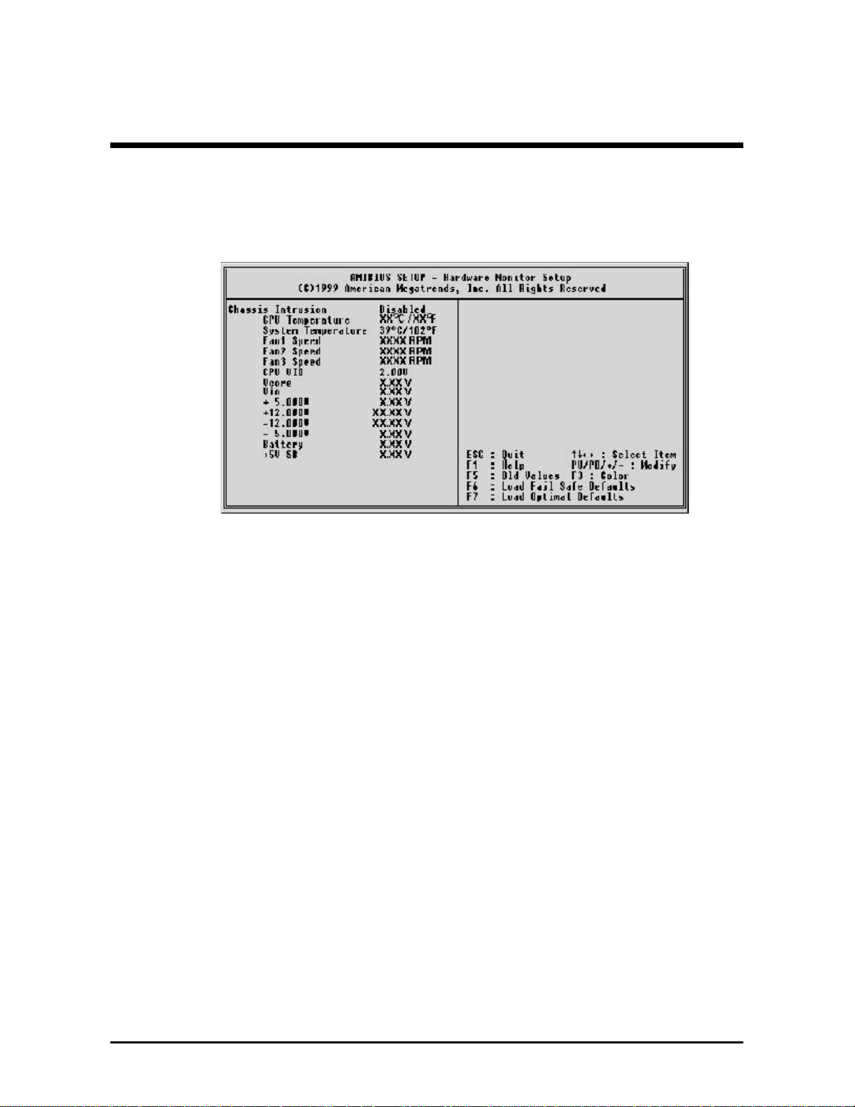
@@ Hardware Monitor Setup
Chassis Intrusion
This item enables to detect any opening the chassis if you sets to
enable.
Ø The choice: Enable, Disable.
CPU Temperature
Since the mainboard supports CPU temperature monitoring and
overheat alert. This item indicates current Processor's temperature.
System Temperature
Since the mainboard supports system and CPU temperature monitoring
and overheat alert. This item indicates current mainboard's
temperature.
Fan1/Fan2/Fan3 Speed
The mainboard can detect the Fan1/Fan2/Fan3 speed in rotations per
minute (RPM).
CPU VID
The mainboard supports CPU and mainboard voltages monitoring. The
onboard hardware monitor is able to detect the CPU voltage(Vcore)
and the voltage output from power supply.
- 74 -

Vcore
The mainboard supports CPU and mainboard voltages monitoring. The
onboard hardware monitor is able to detect the CPU voltage(Vcore)
and the voltage output from power supply.
Vio
This item displays the I/O voltage for reference.
+5V, +12V, -12V, -5V
The onboard hardware monitor is able to detect the voltage output of
Power Supply.
Battery
The onboard hardware monitor is able to detect the Battery voltage.
+5V SB
The onboard hardware monitor is able to detect the +5V StandBy
voltage output from Power Supply.
- 75 -
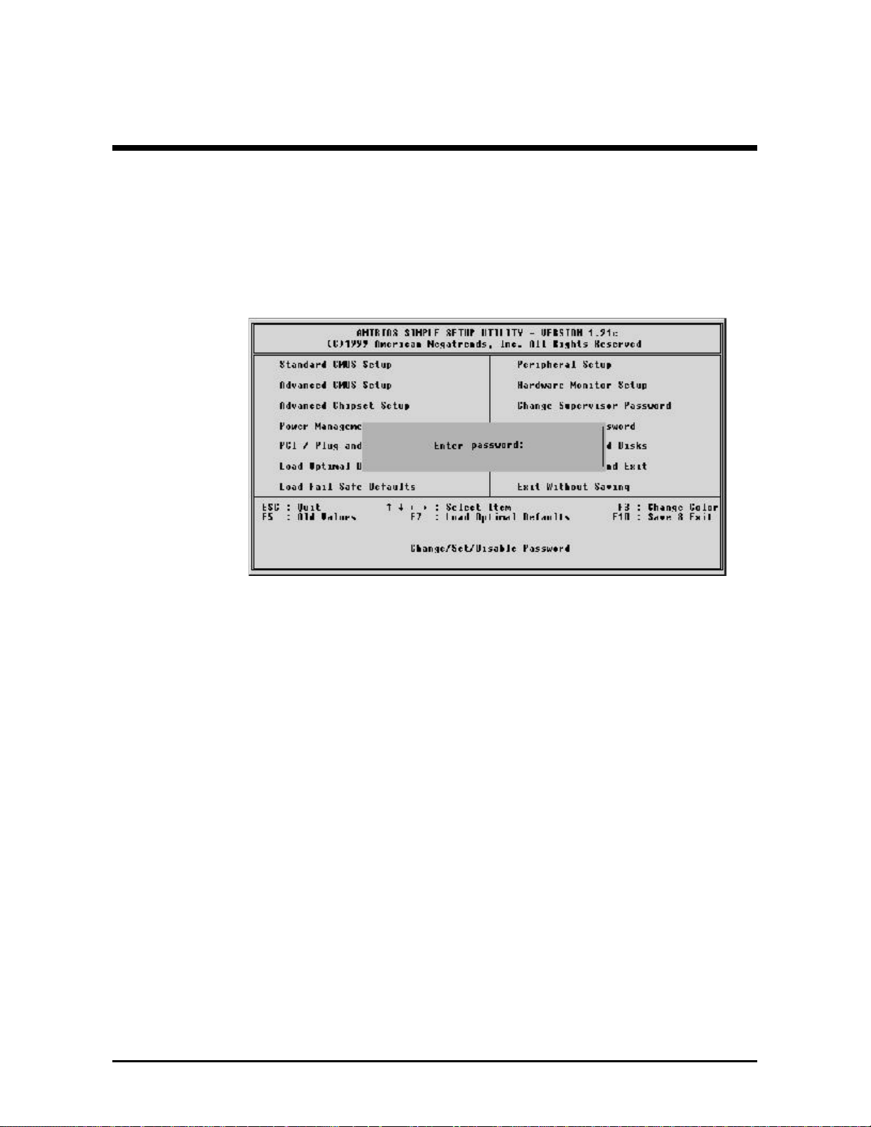
@@ User Password Setting
You can set either supervisor or user password or both of them. The
differences between are:
Supervisor Password and User Setting
The options on the Password screen menu make it possible to restrict
access to the Setup program by enabling you to set passwords for two
different access modes: Supervisor mode and User mode.
In general, Supervisor mode has full access to the Setup options,
whereas User mode has restricted access to the options. By setting
seperate Supervisor and User password, a system supervisor can limit
who can change critical Setup values.
Enter Password
Type the password, up to eight characters, and press <Enter>. The
password typed now will clear any previously entered password from
CMOS memory. You will be asked to confirm the password. Type the
password again and press <Enter>. You may also press <Esc> to
abort the selection and not enter a password.
To disable password, just press <Enter> when you are prompted to
enter password. A message will confirm the password being disabled.
Once the password is disabled, the system will boot and you can enter
Setup freely.
- 76 -

@@ Save & Exit Setup
Pressing <Enter> on this item and a similar dialog box shows up to
ask you for the following confirmation :
Save to CMOS and EXIT (Y/N)? Y
Pressing "Y" stores the selections made in the menus in CMOS - a
special section of memory that stays on after you turn your system off.
The next time you boot your computer, the BIOS configures your
system according to the Setup selections stored in CMOS. After saving
the values the system restarts again.
@@ Exit Without Saving
Pressing <Enter> on this item and a similar dialog box shows up to
ask you for the following confirmation :
Quit without saving (Y/N)? Y
This allows you to exit Setup without storing in CMOS any change.
The previous selections remain in effect. This exits the Setup utility and
restarts your computer.
- 77 -
 Loading...