

Page 1

MB48/MB48N & MB50/MB50N
Intel Pentium 4/Celeron
478-pin Processor
with 400/533 MHz FSB
Based DDR MAINBOARD
User's Manual
Page 2

Shuttle® MB48/MB48N & MB50/MB50N
Intel Pentium 4/Celeron
478-pin Processor
with 400/533 MHz FSB
Based DDR Mainboard
Manual V ersion 1.1
Copyright
Copyright© 2002 by Shuttle® Inc. All Right s Reserved.
This publication, including all photos, illustrations, and software, is protected under interna-
tional copyright laws, with all rights reserved. Reproducing any of the material contained
herein is prohibited without the consent of the publisher.
Disclaimer
Shuttle® Inc. shall not be liable for any incidental or consequential damages resulting from the
performance or use of this product.
This company makes no representations or warranties regarding the contents of this manual.
Information in this manual has been carefully checked for reliability; however , no guarantee is
given as to the correctness of the contents. In the interest of continued product improvement,
this company reserves the right to revise the manual or include changes in the specifications
of the product described within it at any time without notice and without obligation to notify any
person of such revision or changes. The information contained in this manual is provided for
general use by the customers.
Trademarks
Shuttle is a registered trademark of Shuttle Inc.
Intel, Pentium, and Celeron are registered trademarks of Intel Corporation.
PS/2 is a registered trademark of IBM Corporation.
AW ARD is a registered trademark of Award Software Inc.
Microsoft and Windows are registered trademarks of Microsoft Corporation.
General Notice: Other product names used in this manual are ascribed to their respective
owners and acknowledged.
M640
Page 3

T ABLE OF CONTENTS
WHAT'S IN THE MANUAL .....................................................................4
Quick Reference................................................................................................4
About This Manual ............................................................................................4
1 INTRODUCTION ................................................................................. 5
1.1 TO DIFFERENT USERS ..............................................................................5
FIRST-TIME DIY SYSTEM BUILDER.............................................................5
EXPERIENCED DIY USER ..........................................................................5
SYSTEM INTEGRA TOR ...............................................................................5
1.2 ITEM CHECKLIST:.......................................................................................6
2 FEATURES .......................................................................................... 7
2.1 SPECIFICATIONS ........................................................................................7
3 HARDWARE INSTALLATION............................................................10
3.1 STEP-BY-STEP INSTALLATION ...............................................................10
STEP 1 CPU Installation ............................................................................. 11
STEP 2 Set Jumpers..................................................................................13
STEP 3 Install DDR SDRAM System Memory.............................................13
STEP 4 Install Internal Peripherals in System Case .....................................14
STEP 5 Mount the Mainboard on the Computer Chassis.............................15
STEP 6 Connect Front-Panel LEDs/Switches/S peaker/USBs.....................16
STEP 7 Connect IDE and Floppy Disk Drives .............................................17
STEP 8 Connect Other Internal Peripherals.................................................17
STEP 9 Connect the Power Supplies .........................................................18
STEP 10 Install Add-on Cards in Expansion Slots.......................................19
STEP 1 1 Connect External Peripherals to Back-Panel ................................ 20
STEP 12 System Boot Up For the First-Time..............................................21
STEP 13 Install Drivers & Sof tware Components ........................................22
3.2 JUMPER SETTINGS..................................................................................23
JUMPERS & CONNECTORS GUIDE.........................................................24
Jumpers
Clear CMOS Setting (JP1) ........................................................................27
FSB Speed Configuration Setting (JP2) .....................................................27
- 1 -
Page 4

USB3/4 Power-On Setting (JP5)................................................................28
USB5/6 Power-On Setting (JP6)................................................................28
Onboard LAN Setting (JP13) .....................................................................29
Back-Panel Connectors
PS/2 Mouse & PS/2 Keyboard Connectors.................................................30
Parallel Port Connector...............................................................................30
COM1 Port Connector ................................................................................30
VGA Port Connector ...................................................................................30
Line-Out Port Connector .............................................................................30
Line-In Port Connector ................................................................................31
Mic-In Port Connector .................................................................................31
MIDI/Game Port Connector .........................................................................31
USB1/USB2 Port Connectors.....................................................................31
LAN Port Connector (MB48N/MB50N only).................................................31
Front-Panel Connectors
HDD LED Connector (HLED) .....................................................................32
Green LED Connector (GLED) ...................................................................32
Hardware Reset Connector (Reset) ............................................................33
A TX Power On/Off Switch Connector (PWON)............................................33
EPMI Connector (EPMI)..............................................................................34
Power LED Connector (PLED)...................................................................34
Speaker Connector (SPEAKER) ................................................................34
Internal Peripheral Connectors
Enhanced IDE and Floppy Connectors (IDE1/2 & FDC)..............................35
Other Connectors
ATX Power Supply Connectors (JP11 & CN2) ............................................36
CPU and System Fan Connectors (FAN1/2/3) ............................................37
IR Header (JP3)..........................................................................................37
Wake-On-LAN Connector (CN1).................................................................38
Audio CD_IN Connectors (J3/J4)................................................................38
Audio AUX_IN Connector (J5) ....................................................................39
Audio Center/Bass Connector (J2) .............................................................39
SPDIF Ext. Header (JP9)............................................................................40
- 2 -
Page 5

Front-Panel Audio Connector (JP10)...........................................................40
Serial Port Connector (COM2)....................................................................41
Extended USB Headers (JP7/JP8).............................................................41
3.3 SYSTEM MEMORY CONFIGURATION ......................................................42
INST ALL MEMORY.....................................................................................42
UPGRADE MEMORY.................................................................................42
4 SOFTWARE UTILITY .......................................................................43
4.1 Mainboard CD Overview ..........................................................................43
4.2 Install Mainboard Software .....................................................................44
4.2.A Inst all Intel Chipset Driver .............................................................45
4.2.B Install Intel Ultra A T A Driver...........................................................46
4.2.C Install VGA Driver ...........................................................................47
4.2.D Install Audio Driver ........................................................................48
4.2.E Install LAN Driver (MB48N/MB50N only) ......................................49
4.2.F Install USB 2.0 Driver.....................................................................50
4.3 View the User's Manual...........................................................................51
5 BIOS SETUP.....................................................................................52
5.1 ENTER BIOS ..............................................................................................52
5.2 THE MAIN MENU .......................................................................................53
ST ANDARD CMOS FEA TURES ................................................................55
ADV ANCED BIOS FEATURES ..................................................................57
ADVANCED CHIPSET FEATURES ...........................................................60
INTEGRA TED PERIPHERALS ...................................................................63
POWER MANAGEMENT SETUP ..............................................................66
PNP/PCI CONFIGURA TIONS.....................................................................69
PC HEALTH STATUS.................................................................................70
FREQUENCY/RA TIO CONTROL ................................................................71
LOAD FAIL-SAFE DEF AULTS ...................................................................72
LOAD OPTIMIZED DEF AUL TS ...................................................................72
SET SUPERVISOR/USER PASSWORD ...................................................72
Save & Exit Setup.......................................................................................73
Exit Without Saving.....................................................................................73
- 3 -
Page 6

WHAT'S IN THE MANUAL
Quick Reference
Hardware Installation >> Step-by-Step ................................................ Page 10
Jumper Settings >> A Closer Look ...................................................... Page 23
Software Utility >> How to Install ......................................................... Page 43
BIOS Setup >> How to Configure ........................................................ Page 52
About This Manual
For First-Time DIY System Builder ......................................................... Page 5
For Experienced DIY User ...................................................................... Page 5
For System Integrator ............................................................................. Page 5
- 4 -
Page 7

1 INTRODUCTION
1.1 T o Different Users
First-Time DIY System Builder
Welcome to the DIY world! Building your own computer system is not as difficult as you may think. To make your first computer DIY experience successful,
right from the start, we have designed
step-by-step fashion for all the first-time DIY system builders. Prior to installation, we suggest you read the whole manual to gain a complete understanding
of your new MB48/N or MB50/N mainboard.
Experienced DIY User
Congratulate on your purchase of the MB48/N or MB50/N mainboard. You
will find installing your new MB48/N or MB50/N mainboard is quite easy.
Bundled with an array of onboard functions, the highly-integrated MB48/N or
MB50/N mainboard provides you with a total solution to build the stablest and
most reliable system. Referring to section
4 Software Utility4 Software Utility
4 Software Utility, you will find how to work out your new mainboard.
4 Software Utility4 Software Utility
ter 5 BIOS Setupter 5 BIOS Setup
ter 5 BIOS Setup also contains the relevant information on how to tune up
ter 5 BIOS Setupter 5 BIOS Setup
your system to achieve higher performance.
Chapter 3 Hardware InstallationChapter 3 Hardware Installation
Chapter 3 Hardware Installation in a
Chapter 3 Hardware InstallationChapter 3 Hardware Installation
3.2 Jumper Settings3.2 Jumper Settings
3.2 Jumper Settings and
3.2 Jumper Settings3.2 Jumper Settings
ChapterChapter
Chapter
ChapterChapter
Chap-Chap-
Chap-
Chap-Chap-
System Integrator
You have wisely chosen MB48/N or MB50/N to construct your system.
MB48/N incorporates all the state-of-the-art technology of the 845GV chipset
from Intel; MB50/N, of the 845GE chipset from intel. Each integrates the most
advanced functions you've ever found in a compact Micro ATX board.
This manual adopted in MB48, MB48N, MB50, and MB50N mainboards
at the same time. The difference among them is that MB48N/MB50N
equips with onboard LAN. In the manual, if there are some standards,
characters, equipment or software only appeared or adopted by MB48,
MB48N, MB50, or MB50N; it will be mentioned
MB48N onlyMB48N only
MB48N only,
MB48N onlyMB48N only
MB50/N onlyMB50/N only
MB50/N only, or
MB50/N onlyMB50/N only
MB50N only)MB50N only)
MB50N only)
MB50N only)MB50N only)
(MB48/N only(MB48/N only
(MB48/N only,
(MB48/N only(MB48/N only
- 5 -
Page 8
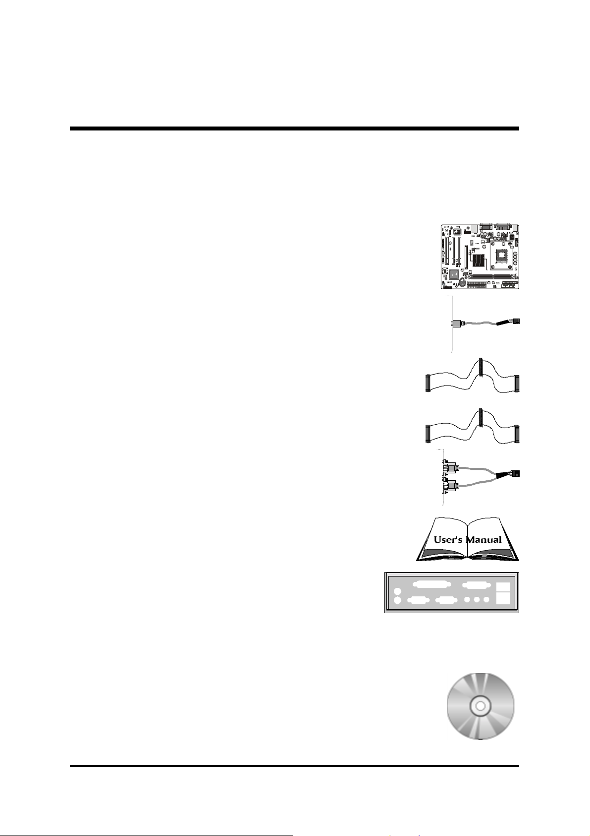
1.2 Item Checklist:
A
0
0
00
Check all items with your MB48/N or MB50/N mainboard to make sure
nothing is missing. A complete package should include:
! One Shuttle MB48/N or MB50/N Mainboard
! One Audio Cable (Central/Bass Channel)
! One ATA
100/66/33100/66/33
100/66/33 Ribbon Cable
100/66/33100/66/33
! One Floppy Ribbon Cable
! One Twin-Port USB Cable
(optional)(optional)
(optional)
(optional)(optional)
! MB48/N & MB50/N User's Manual
1
1
F
A
r
J 2
u
HE-MX2021
on
d
t
io
0226
J P10
1
J
P
5
1
JP 9
PCI3
AUX_INCENTER/BASS SPDIF Ext.
J 5
CD_IN
J 4 J 3
CD_IN
1
USB 5&6
J P
6
1
Winbond
W49V002FAP
214654701
202WHSA
AMS1117
0227
J P 12
SPEAKER EPMI
FAN2
PCI2
PCI1
1
J P
CN 2
2
ATX 12V
AGP
J
P
13
1
1
USB 3&4
KORE
FW82801DB
L2171C0/
SL66K
INTEL 01
P J 27
S K 34
C
CN 1
WOL
I
J
D
P
E
2
1
22AC8YKHCT
22AC8YKHCT
1
I
1
D
1
E
1
HLED
++---
1
Reset
+
GLED
PWONPLED
KB 1
C
I
JP 3
R
1
F
A
N
1
F
A
N
3
1
! I/O Shielding
! One Bundled CD-ROM, including:
" MB48/N & MB50/N user's manual in PDF format
" Intel Chipset Driver
" IDE Driver
" VGA Driver
" Audio Driver
" LAN Driver (
MB48N/MB50N onlyMB48N/MB50N only
MB48N/MB50N only)
MB48N/MB50N onlyMB48N/MB50N only
" USB 2.0 Driver
" Award Flashing Utility
- 6 -
Page 9

2 FEA TURES
MB48/N or MB50/N mainboard is dedicatedly designed for demanding PC users who
desire high performance and maximum intelligent features in a compact package.
2.1 Specifications
!!
! CPU Support
!!
Intel Pentium 4/Celeron, 478-pin processors with 400/533MHz FSB.
!!
! Chipset
!!
Features Intel 845-GV (MCH) for MB48/N, or 845-GE (MCH) for MB50/N,
and Intel 82801DB (ICH4).
!!
! Onboard 10/100Mb/s LAN
!!
The Realtek RTL8100B incorporated in the chipset provides the mainboard
with integrated Fast Ethernet capabilities.
!!
! CPU FSB Configuration
!!
Provides jumper J2 to configure front side bus at 400/533MHz.
!!
! AC'97 Audio CODEC
!!
Supports 18-bit ADC and DAC resolutions, and four analog line-level stereo
inputs.
Compliant with AC'97 2.2 specifications.
!!
! Versatile Memory Support
!!
184-pin184-pin
Two
184-pin
184-pin184-pin
MB48/N; support up to 2GB of PC1600, PC2100, or PC2700 for MB50/N.
Compliant with
!!
! PCI Expansion Slots
!!
Provides three 32-bit PCI slots.
!!
! AGP Expansion Slot (MB50/N only)
!!
Provides one AGP slot that supports up to 4X AGP device.
DIMMDIMM
DIMM slots support up to 2GB of PC1600 or PC2100 for
DIMMDIMM
DDRDDR
DDR SDRAM module.
DDRDDR
!!
! USB 2.0 Interface Onboard
!!
" 2 x USB ports on back-panel and two extended USB headers (4 ports) on
front-panel.
- 7 -
Page 10

!!
! I/O Interface
!!
Provides a variety of I/O interfaces:
" 2 x PS/2 ports for Mouse and Keyboard
" 1 x Parallel port
" 1 x Serial port
" 1 x VGA port
" 1 x MIDI/Game port
" 1 x Line-Out port
" 1 x Line-In port
" 1 x Mic-In port
" 1 x LAN port
" 2 x USB ports
!!
! PCI Bus Master IDE Controller Onboard
!!
Two ultra DMA 100/66/33 bus master dual-channel IDE ports support up to
four IDE devices (one Master and one Slave per channel).
The IDE bus implements data transfer speeds to 100MB/sec and supports enhanced PIO modes.
80-pin cable backward compatible legacy ATAPI devices, ATAPI IDE CD-ROM,
CD-R, CD-RW, and LS-120 supports.
!!
! ATX Power Supply Connector
!!
ATX power supply unit can be connected to the onboard 20-pin Pentium 4
standard ATX power connector, and 4-pin ATX power connector. The unit
supports Suspend and Soft-On/Off modes by the dual-function power button.
!!
! Advanced Configuration and Power Interface
!!
Features four power-saving modes: S1 (Snoop), S3 (Suspend to RAM), S4
(Suspend to DISK), and S5 (Soft-Off). ACPI provides more efficient energysaving features controlled by your operating system that supports OS Direct
Power Management (OSPM) functionality.
!!
! System BIOS
!!
Provides licensed Award BIOS V6.0 PG on the 2Mb Flash EEPROM, and
supports Green PC, Desktop Management Interface (DMI).
- 8 -
Page 11

!!
! Form Factor
!!
System board conforms to the Micro ATX specification.
Board dimension: 244mm x 200mm.
!!
! Advanced Features
!!
Low EMI -Low EMI -
"
Low EMI - Built in spread spectrum. Unused PCI/SDRAM slots are shut off
Low EMI -Low EMI -
by the automatic clock for reducing EMI.
Dual Function Power Button - Dual Function Power Button -
"
Dual Function Power Button - The system can be in any of the two
Dual Function Power Button - Dual Function Power Button states: one is Suspend mode and the other is Soft-Off mode. Pushing the
power button for less than 4 seconds places the system into Suspend
mode. When the power button is pressed for longer than 4 seconds, the
system will enter Soft-Off mode.
Modem Ring Power-On - Modem Ring Power-On -
"
Modem Ring Power-On - The system can be powered on automatically
Modem Ring Power-On - Modem Ring Power-On -
by the activation of modem ringing.
CPU Clock SettingCPU Clock Setting
"
CPU Clock Setting - This item allows users to adjust CPU host clock in
CPU Clock SettingCPU Clock Setting
BIOS.
CPU Multiplier SettingCPU Multiplier Setting
"
CPU Multiplier Setting - This item allows users to adjust CPU multiplier
CPU Multiplier SettingCPU Multiplier Setting
in BIOS.
!!
! Intelligent Features
!!
Voltage Monitoring -Voltage Monitoring -
"
Voltage Monitoring - Monitors various voltages of key elements, such as
Voltage Monitoring -Voltage Monitoring the CPU, and other critical system voltage levels to ensure a stable current
passing through mainboard components.
Fan Status MonitoringFan Status Monitoring
"
Fan Status Monitoring
Fan Status MonitoringFan Status Monitoring
fan is monitored by RPM, with which the cooling fan is required.
Temperature Monitoring -Temperature Monitoring -
"
Temperature Monitoring - This item allows users to make sure whether
Temperature Monitoring -Temperature Monitoring the CPU or system runs under a suitable temperature.
--
- To prevent the CPU from overheating, the CPU
--
- 9 -
Page 12

3 HARDWARE INSTALLA TION
A
A
A
Before removing/installing any of these devices: CPU, DIMMs, Add-OnBefore removing/installing any of these devices: CPU, DIMMs, Add-On
Before removing/installing any of these devices: CPU, DIMMs, Add-On
Before removing/installing any of these devices: CPU, DIMMs, Add-OnBefore removing/installing any of these devices: CPU, DIMMs, Add-On
Cards, and Cables, please unplug the onboard power connector.Cards, and Cables, please unplug the onboard power connector.
Cards, and Cables, please unplug the onboard power connector.
Cards, and Cables, please unplug the onboard power connector.Cards, and Cables, please unplug the onboard power connector.
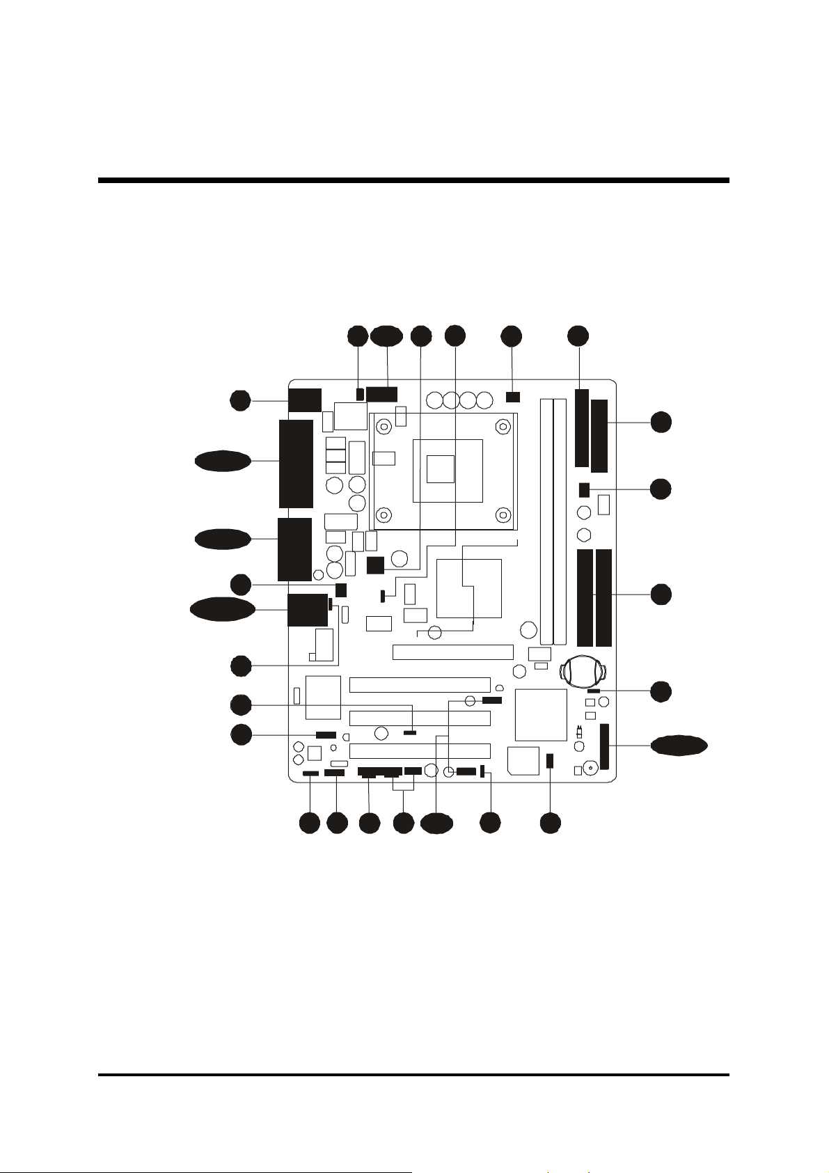
This section outlines how to install and configure your mainboard. Referring to the following mainboard layout helps you identify various jumpers, connectors, slots, and ports.
Steps described herein will lead you to a quick and correct installation of your system.
3.1 Step-by-Step Inst allation
Accessories Of MB48/N & MB50/N
FSB Speed Configuration Setting - JP2
COM2
IR - JP3
SOCKET 478
FAN1
Two DIMM Slots
PS/2 Keyboard and
PS/2 Mouse Conne cto rs
Serial Port
Connector
Parallel Port
Connector
KB 1
JP 3
IR
1
C
FAN
1
1
ATXPWR - JP11
FAN
3
Floppy Connector
VGA Port
ATX 12V - CN2
Line-Out/Line-In/Mic-In &
MIDI/Game Connectors
ATX 12V
FAN2
USB & LAN Connectors
USB P OWER-ON
Setting - JP5
1
2
N
A
F
5
P
J
0226
HE-MX2021
AGP Slot (MB50/N only)
Three PCI Slots
Front
Front Audio - JP10
Audio
1
Onboard Audio CODEC
CENTER/BASS - J2
SPDIF Ext. Header - JP9
1
CENTER /BASS SPDIF Ext.
PCI1
PCI2
J P10
PCI3
1
JP 9
J 2
Enabled/Di sa bled LAN - JP13
CN 2
1
2
P
J
AGP
J 5
J 4 J 3
UX_IN
CD_IN
CD_IN - J3
CD_IN - J4
AUX _ IN - J5
1
USB 3&4
7
P
J
1
P
1
3
J
8
P
J
USB 5&6
1
CD_IN
1
J
P
6
Extended USB Connectors - JP7/JP8
USB POWER-ON Setting - JP6
Wake -On-LAN (WOL) - CN1
1
1
IDE2
IDE
1
P J 27
S K 34
1
P
1
J
HCT00
22
FW8 2801DB
L2171C0/
SL66K
C
INTEL 01
KOREA
WOL
CN 1
214654701
202WHSA
W49V002FAP
Winbond
C8 YK
HCT00
22
C8 YK
1
-
+
GLED
-
+
Re setHLED
PWON
+
PLE D
-
J P 12
SPEAKER EPMI
0227
AMS1117
FAN3
Inte l 845GV/ 845GE Two IDE Connect or s
Clear CMOS Jumper - JP1
Front Panel Header - JP12
Intel ICH4
- 10 -
Page 13

Step 1
CPU Installation:
This mainboard supports Intel Pentium 4/Celeron Socket 478 series CPU.
Please follow the step as listed below to finish the CPU installation.
Note the CPU orientation as you place it into the CPU socket.
1. Pull up the CPU socket lever to 90-degree angle.
CPU socket lever up to
90-degree angle
2. Locate Pin 1 in the socket and look for a black dot or cut edge on the CPU
upper interface. Match Pin 1 and cut edge, and insert the CPU into the
socket.
CPU Pin 1 and cut edge
- 11 -
Page 14

3. Press down the CPU socket lever and the CPU installation is completed.
Note:Note:
Note: The CPU might be damaged if you do not match the CPU
Note:Note:
socket Pin 1 and cut edge well.
4. Intel Pentium 4/Celeron processor requires a set of heatsink and fan to cool
down the processor. You need to purchase a heatsink and fan if they are not
bundled with your CPU. Required is that install the set and plug its cable
in the CPU fan power connector. Note that there are kinds of CPU fan
connectors. Normally, if your mainboard supports a hardware monitoring
function, a 3-pin fan power connector can have your system detect the CPU
fan's speed. A CPU fan with a 2-pin or 4-pin fan power connector does not
support the detection of the CPU fan's speed, and must directly be connected to the system's power supply unit.
- 12 -
Page 15

Step 2.
Set Jumpers
The default jumper settings have been set for the common usage standard of
this mainboard. Therefore, you need not to reset the jumpers unless you require special adjustments as any of the following cases:
1. Clear CMOS Setting
2. FSB Speed Configuration Setting
3. USB3/4 Power-On Setting
4. USB5/6 Power-On Setting
5. Onboard LAN Enabled/Disabled Setting
For first-time DIY system builders, we recommend that you not change the
default jumper settings if you are not quite familiar with the mainboard configuration procedures. The factory-set default settings are tuned for optimum
system performance. For advanced users who prefer to customize their
system, section
how to configure your mainboard manually.
3.2 Jumper Settings3.2 Jumper Settings
3.2 Jumper Settings provides the detailed information on
3.2 Jumper Settings3.2 Jumper Settings
Step 3
Install DDR SDRAM System Memory
To install memory, insert DDR SDRAM memory module(s) in the DIMM
banks. Note that DDR SDRAM modules are directional and will not go in the
DIMM banks if they are not properly oriented. After the module is fully inserted into the DIMM bank, lift the clips of both sides of the DIMM bank to
lock the module in place.
DDR SDRAM
- 13 -
Page 16

Step 4
Install Internal Peripherals in System Case
Before you place the mainboard into your system case, we recommend that
you first assemble all the internal peripheral devices into the computer housing, including, but not limited to, the hard disk drive (IDE/HDD), floppy disk
drive (FDD), CD-ROM drive, and ATX power supply unit.
To install IDE & FDD drives, follow these procedures:
1. Set the required jumpers on each device according to the instructions provided by the manufacturer. (IDE, HDD, and CD-ROM have to set jumpers
to Master or Slave mode depending on whether you install more than one
device of each kind.)
2. Connect the IDE cable and FDD cable on the back-panel of the internal
peripheral devices to the corresponding headers on board. Note that the
cable should be oriented with its colored stripe (usually red or magenta)
connected to pin#1 of the IDE or FDD connector on the mainboard and
on the device as well.
3. Connect an available power cable from your system power supply unit to
the back-panel of each peripheral device. Note that the power cable is directional and cannot fit in if not properly positioned.
- 14 -
Page 17
Step 5
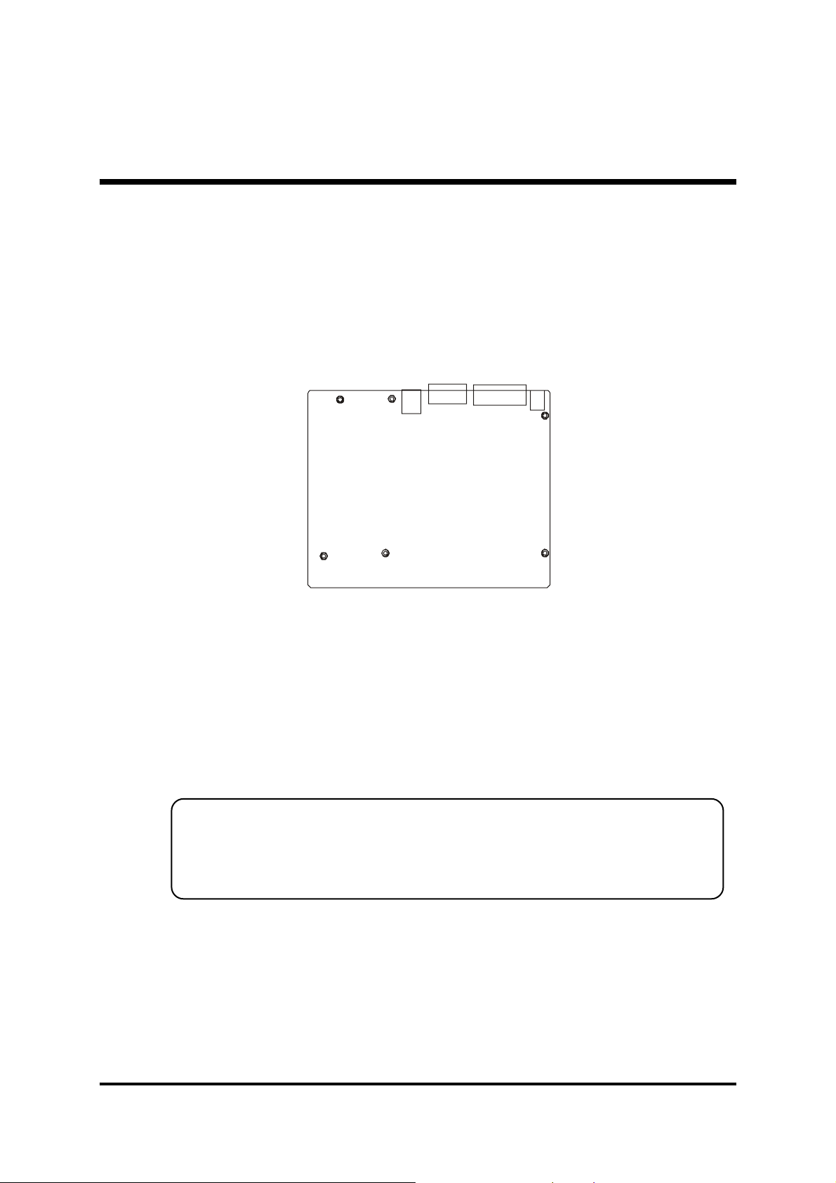
Mount the Mainboard on the Computer Chassis
1. You may find there are a lot of mounting holes on your computer chassis
and mainboard. To match the holes on both properly, the key point is to
make the back-panel of the mainboard in a close fit with your system case,
as shown below.
2. Position the studs between the chassis and the mainboard. The studs are
used to fix the mainboard and to keep a certain distance between the
them, for avoiding any electrical shorts in-between
(If your computer case is already equipped with mounting studs, you need
to tighten the screws to attach the mainboard.)
Note:Note:
Note:In most computer housings, you can find 4 or more holes to place
Note:Note:
studs for fixing the mainboard. If there aren't enough matching holes,
screw at least 4 studs to ensure the proper attachment of the mainboard.
- 15 -
Page 18
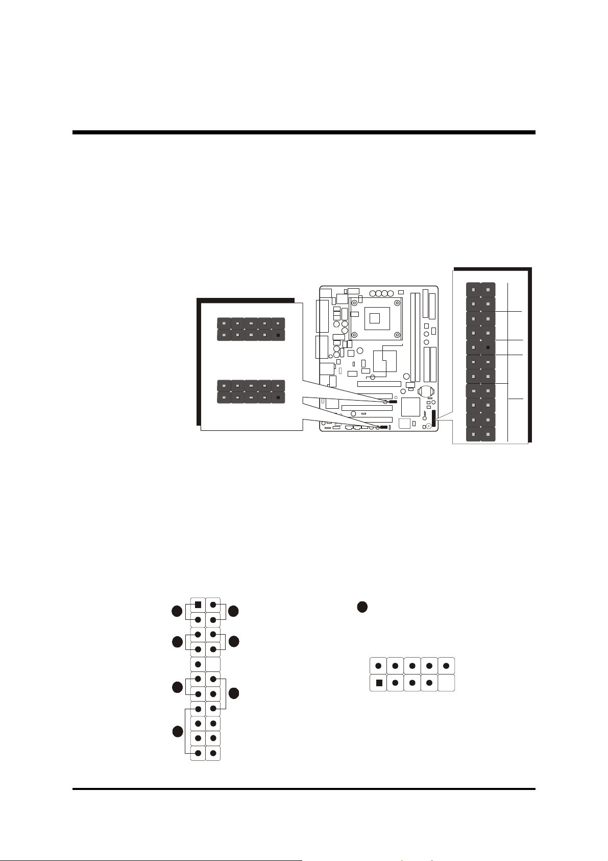
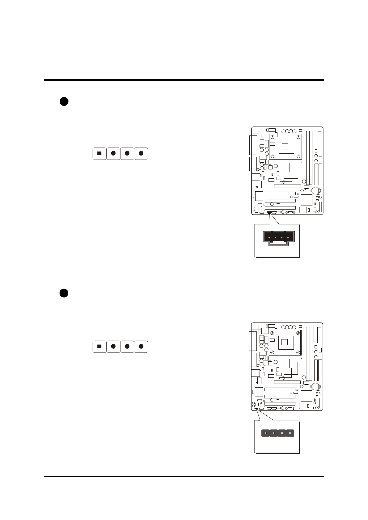
Step 6
1
+
-
R
e
setHL
E
D
G
L
E
D
SPE
A
KER
EPM
I
P
W
O
NPLED
1
6
2
4
D1-
D1+
USB port 4 / 6
USB port 3 / 5
Connect Front-Panel LEDs/Switches/Speaker/USBs
You can find there are several cables existing in the system case and originating from the front-panel devices (HDD LED, Green LED, Reset switch, PC
Speaker, and USB devices etc.). These cables serve to connect the front-panel
LEDs, switches, speaker, and USB connectors to JP12, JP7, and JP8, as shown
below.
JP 7
1
-
+
USB 3&4
JP 8
1
USB 5&6
1. HDD LED (HLED)
2. Green LED (GLED)
3. Hardware Reset Switch (Reset)
4. ATX Soft Power On/Off (PWON)
5. Hardware System Management Interface (EPMI)
6. Power LED (PLED)
7. PC Speaker (SPEAKER)
8. Extended USB Headers (USB 3&4/USB 5&6)
1
3
8
+5V
+
2
1
P
J
USB
USB
GND
N/A
-
5
7
1
+5V
USBD0-
USBD0+
KEY
GND
- 16 -
Page 19

Step 7
IDE1
1
FDC
AUX_IN
CENTER/BASS
1
Connect IDE and Floppy Disk Drives
1. IDE cable connectors
2. Floppy cable connector
IDE2
1
11
Step 8
Connect Other Internal
Peripherals
1. CD_IN, AUX_IN, and CENTER/
BASS connectors
- 17 -
J 2
1
1
1
J 3
J 4
CD_INJ 5
CD_IN
Page 20

2. IR connector
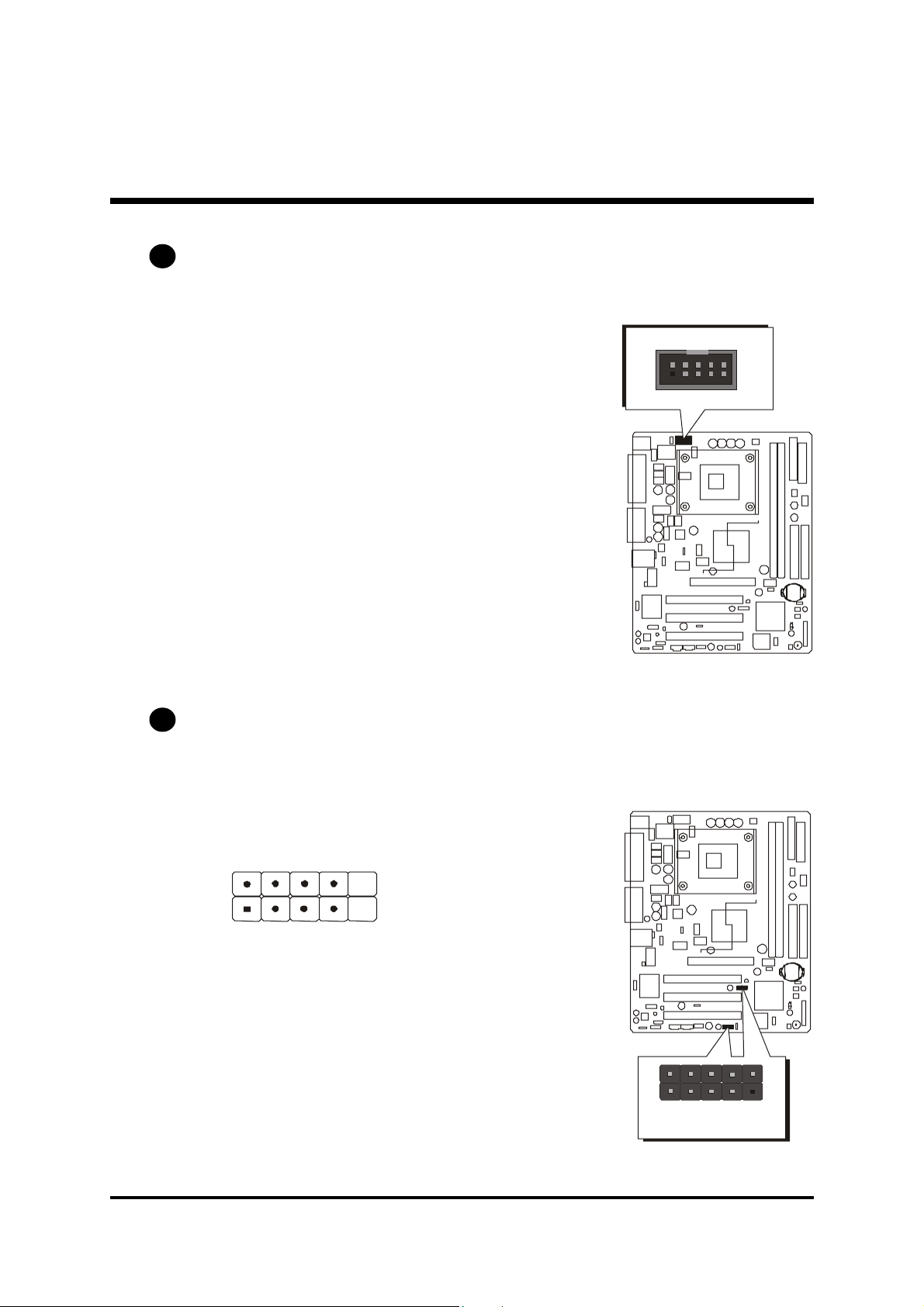
Step 9
Connect the Power Supplies
1. System power connectors
JP 3
IR
1
- 18 -
V
2
1
X
T
2
A
N
C
Page 21

Step 10
Install Add-On Cards in Expansion Slots
1. Accelerated Grapics Port (AGP) Card
2. PCI Card
(MB50/N only)(MB50/N only)
(MB50/N only)
(MB50/N only)(MB50/N only)
- 19 -
Page 22

Step 11
Connect External Peripherals to Back-Panel
You are now ready to connect the external peripherals to your system's backpanel.
1. PS/2 Mouse and PS/2 Keyboard
2. Parallel Port
3. COM Port
4. VGA Port
5. MIDI/Game Port
6. Audio Line-Out/Line-In/Mic-In Ports
7. LAN Port
8. USB Port1/2
1
3
2
foxconn
4
5
6
7
8
- 20 -
Page 23

Step 12
System Boot Up For the First-Time
To ensure your system completedly and correctly installed, please refer to the
above installation steps once again before first booting up your system.
1. Insert a system-bootable floppy disk (DOS 6.2X, Windows 9X/NT, or
others), which contains the FDISK and FORMAT utilities.
2. Turn on the system power.
3. First, you need to use the FDISK utility to create a primary partition of the
hard disk. You can also add an extended partition if your primary partition does not use all of the available hard disk space. If you choose to
add an extended partition, you will have to create one or more logical
partitions to occupy all the space available to the extended partition. The
FDISK utility will assign a drive letter (i.e. C:, D:, E:,......) to each partition
shown in the FDISK program. After the FDISK procedure, reboot your
system by using the same disk.
Note:Note:
Note: DOS 6.2X and Windows 95A can only support up to 2.1GB of HDD
Note:Note:
partition. If you use the FDISK utility with one of the operating systems mentioned above, you can only install your HDD into any partitions no larger than 2.1GB.
4. Now, use the FORMAT utility to format all the partitions you've created.
When formatting the primary partition (C:), key in the command, "FORMAT C:/S."
Note:Note:
Note: FORMAT C:/S can transfer all the necessary system files into the pri-
Note:Note:
mary partition of your hard disk. Afterwards, your HDD will become
a bootable drive.
5. Install all the necessary drivers for CD-ROM, Mouse, etc.
6. Setup the complete operating system according to your OS installation
guide.
- 21 -
Page 24

Step 13
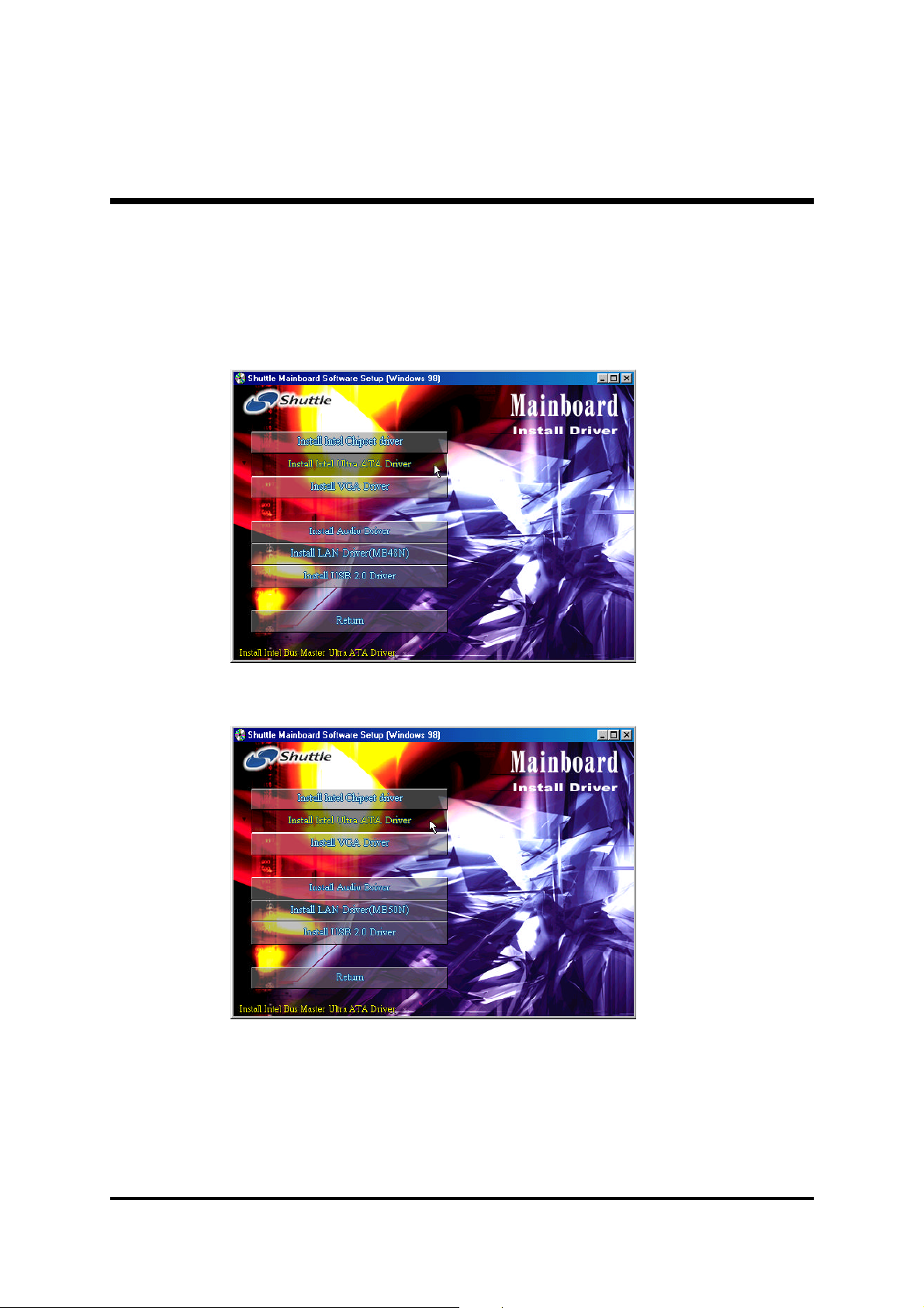
Install Drivers & Software Components
Please note that all the system utilities and drivers are designed for Win 9x/
2000/ME/NT/XP operating systems. Make sure your operating system is
already installed before running the installation programs on CD-ROM.
1. Insert the MB48/N & MB50/N bundled CD-ROM into your CD-ROM
drive. The auto-run program will display the main installation window on
screen.
2. Choose "Install Mainboard MB48/N Software" and complete it, or
3. Choose "Install Mainboard MB50/N Software" and complete it.
4. Choose "Install Intel Chipset driver" and complete it.
5. Choose "Install Intel Ultra ATA Driver" and complete it.
6. Choose "Install VGA Driver" and complete it.
7. Choose "Install Audio Driver" and complete it.
8. Choose "Install LAN Driver" and complete it
9. Choose "Install USB 2.0 Driver" and complete it.
10. Quit (from the auto-run installation program).
(MB48N/MB50N only)(MB48N/MB50N only)
(MB48N/MB50N only).
(MB48N/MB50N only)(MB48N/MB50N only)
- 22 -
Page 25

3.2 Jumper Settings
Several hardware settings are made through the use of mini jumpers to connect jumper pins on the mainboard. Pin #1could be located at any corner of
jumpers, and the corner with a white right angle stands for Pin #1. There are
several types of Pin #1 as shown below:
3-pin and multi-pin (>3) jumpers shown as follows:
Pin #1 to the left:
Pin #1 on the top:
Pin #1 to the right:
Pin #1 on the bottom:
Jumpers with two pins capped are shown as for Close [On] or
for Open [Off]. To do this, please place a plastic mini cap on the desired pair
of pins.
Caution!Caution!
Caution!
Caution!Caution!
1. Do not remove the mainboard from its antistatic protective packaging
until you are ready to install it.
2. Carefully hold the mainboard by its edges and avoid touching its
components. When putting the mainboard down, place it on top of its
original packaging film, with the component side up.
3. Wear an antistatic wrist strap or take other suitable measures to prevent
electrostatic discharge (ESD) as handling this equipment.
- 23 -
Page 26
Jumpers & Connectors Guide
Refer to the mainboard layout on page 10 and this section to help you identify jumpers, slots, and connectors along with their assigned functions during
installation:
B1
B2~B4
B5~B8
E2
B9~B10
A3
A5
E9
E3
E1 E2
E10
A2
D1
E1
E2
D1
A1
C1~C7
E7
E8
E6
E11
A4
E4E5
CPU/Memory/Expansion Slots
Socket 478 : CPU socket for Pentium 4/Celeron, 478-pin processors
DIMM1/2 : Two DIMM slots for 128, 256, 512 MB, and 1GB of
2.5V DDR SDRAM
(The total installed memory does not exceed 2GB.)
AGP : One 4X AGP slot
(MB50/N only)(MB50/N only)
(MB50/N only)
(MB50/N only)(MB50/N only)
PCI : Three 32-bit PCI expansion slots
- 24 -
Page 27

Jumpers
A1
A2
A3
JP1 : Clear CMOS setting
JP2 : FSB speed configuration setting
JP5 : USB3/4 power-on setting
A4
A5
JP6 : USB5/6 power-on setting
JP13 : Onboard LAN setting
Back-Panel Connectors
MS : PS/2 mouse port
B1
KB : PS/2 keyboard port
B1
B2
B3
B4
B5
B6
B7
B8
B9
B10
PRN1 : Parallel port (printer)
COM1 : Serial port
VGA1 : VGA port
LINE-OUT : Line-Out port
LINE-IN : Line-In port
MIC-IN : Mic-In port
MIDI/GAME : MIDI/Game port
USB : USB1/USB2 ports
LAN1 : LAN port
Front-Panel Connectors
HLED : HDD LED
C1
C3
GLED : Green LED
Reset : Hardware reset switch
PWON : ATX power on/off switch
EPMI : EPMI connector
PLED : Power LED
SPEAKER : Speaker connector
C2
C4
C5
C6
C7
(MB48N/MB50N only)(MB48N/MB50N only)
(MB48N/MB50N only)
(MB48N/MB50N only)(MB48N/MB50N only)
Internal-Peripheral Connectors
IDE1 : IDE primary interface (dual-channel)
D1
IDE2 : IDE secondary interface (dual-channel)
D1
FDC : Floppy disk drive interface
D1
- 25 -
Page 28

Other Connectors
E1
JP11/CN2 : ATX power supply connectors
E2
FAN1 : CPU fan connector
E2
FAN2 : System fan connector
E2
FAN3 : System fan connector
E3
JP3 : IR header
CN1 : Wake-On-LAN connector
E4
E5
J3/J4 : Audio CD_IN connectors
J5 : Audio AUX_IN connector
E6
J2 : Audio Center/Bass connector
E7
JP9 : SPDIF Ext. header
E8
JP10 : Front-panel audio connector
E9
COM2 : Serial port connector
E10
JP7/ JP8 : Extended USB headers (USB 3&4/USB 5&6)
E1 1
- 26 -
Page 29
F Jumpers
1
1
1
J P
1
1
1
1
A1
Clear CMOS Setting (JP1)
JP1 is used to clear CMOS data. Clearing CMOS will result in permanently
erasing previous system configuration settings and the original factory-set
system settings.
Step 1. Turn off the system power (PC-->Off).
Step 2. Remove the ATX power cable from the ATX power connector.
Pin 1-2 (Default)
Pin 2-3 (Clear CMOS)
Step 3. Remove the jumper cap from pins 1-2.
Step 4. Place the jumper cap on pins 2-3 for a few seconds.
Step 5. Restore the jumper cap to pins 1-2.
Step 6. Plug the ATX power cable into the ATX power connector.
Step 7. Turn on the system power (PC-->On).
A2
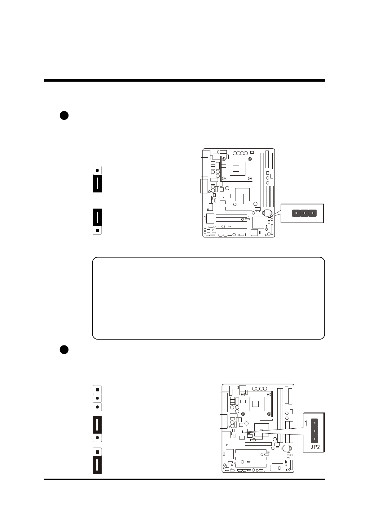
FSB Speed Configuration Setting (JP2)
MB48/N or MB50/N provides JP2 to set front side bus at 400/533MHz. Insert
the mini-jumper cap on pins 1-2 to set FSB at 400MHz. Removing the cap
will set FSB at 533MHz.
Open: 533MHz
Pin 1-2: 400MHz
Pin 2-3: Auto
- 27 -
Page 30
A3
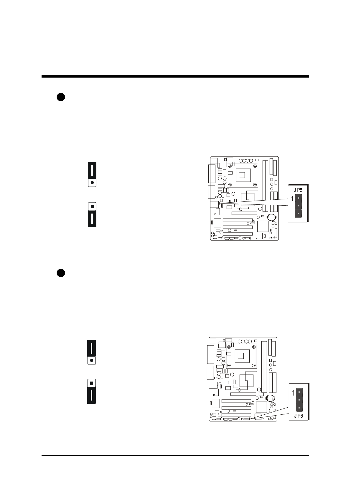
USB3/4 Power-On Setting (JP5)
MB48/N or MB50/N provides JP5 to have USB devices connected to backpanel stay power-on from soft-off stage.
Place the jumper cap on pins 2-3 to enable the USB device (USB 3&4) stay
power-on on back-panel.
1
Pin 1-2 (Disabled/Default)
(USB 5V function)
1
Pin 2-3 (Enabled)
(USB 5VSB function)
A4
USB5/6 Power-On Setting (JP6)
MB48/N or MB50/N provides JP6 to have USB devices connected to backpanel stay power-on from soft-off stage.
Place the jumper cap on pins 2-3 to enable the USB device (USB 5&6) stay
power-on on back-panel.
1
Pin 1-2 (Disabled/Default)
(USB 5V function)
1
Pin 2-3 (Enabled)
(USB 5VSB function)
- 28 -
Page 31
A5
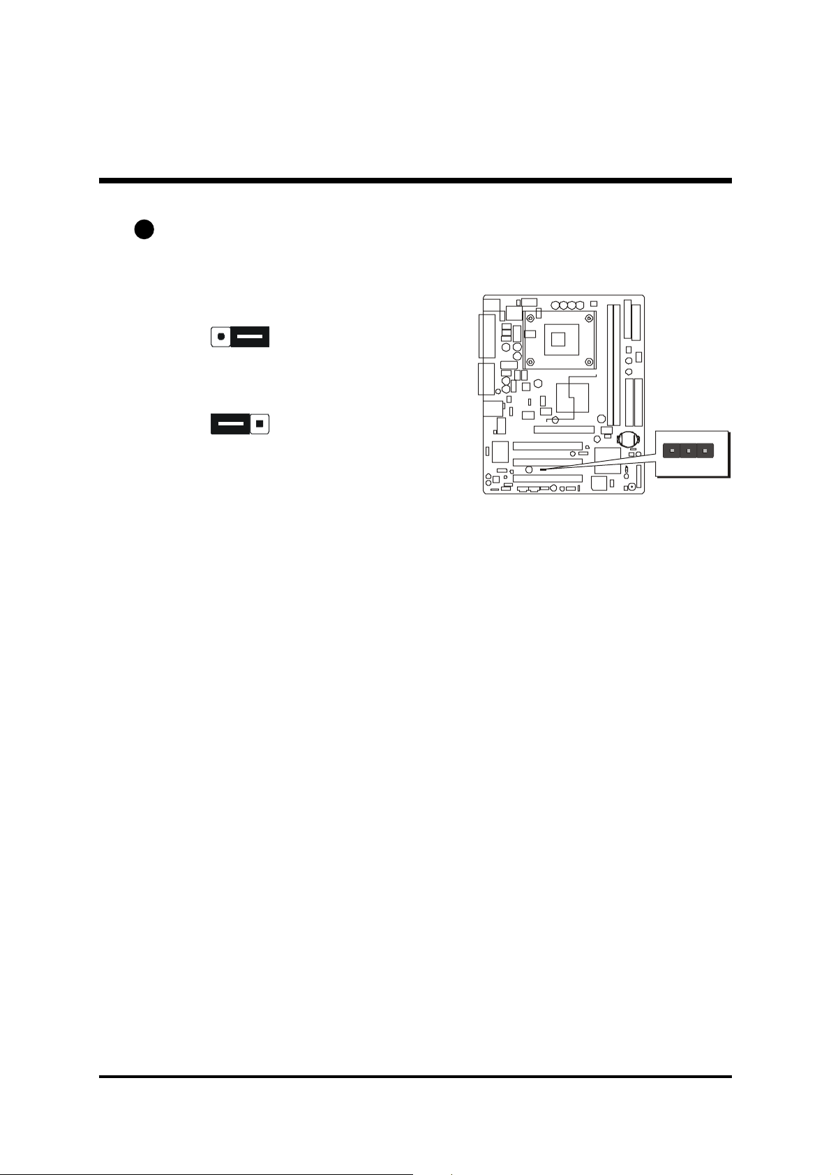
Onboard LAN Setting (JP13)
JP13 is used to enable or disable the built-in LAN adapter.
Pin 1-2 (Enabled)
1
1
Pin 2-3 (Disabled)
1
J
1
P
3
- 29 -
Page 32
!!
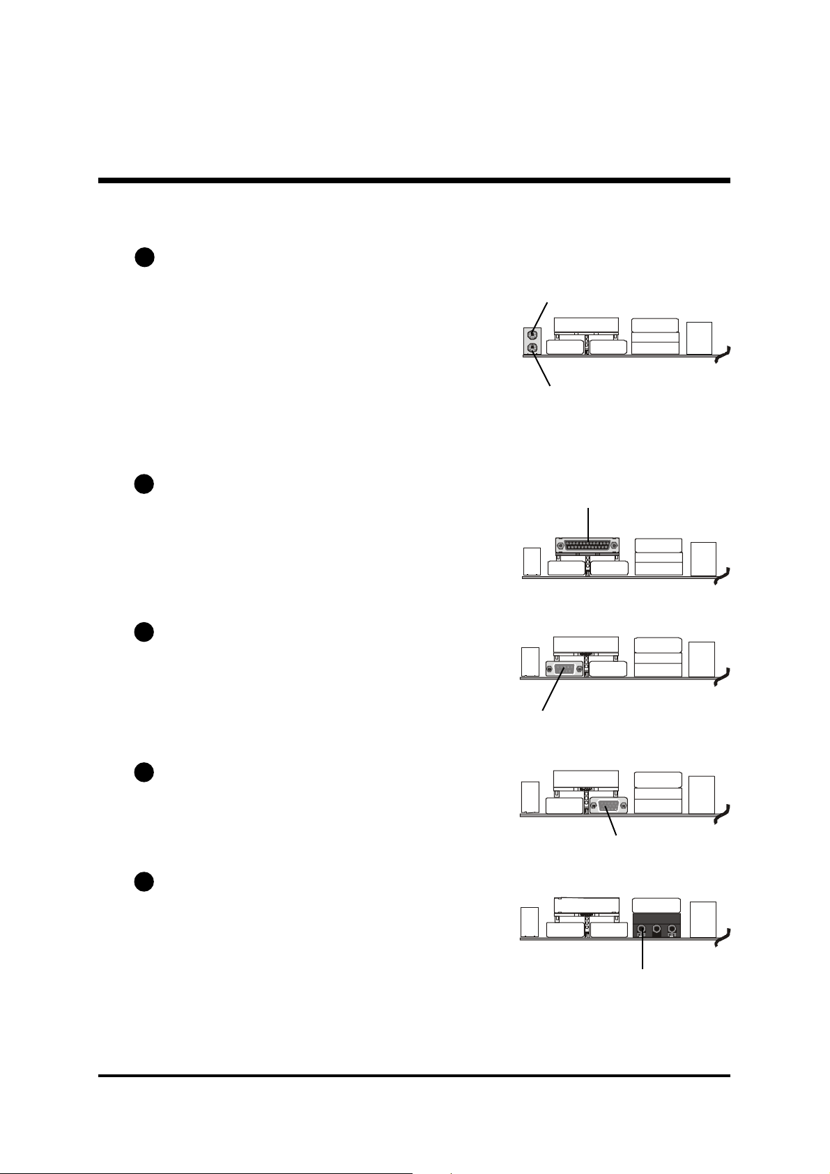
! Back-Panel Connectors
!!
B1
PS/2 Mouse & PS/2 Keyboard Connectors
Two 6-pin female PS/2 Mouse & Keyboard
connectors are located on the rear panel of
the mainboard. In a desktop computer, the
PS/2 Mouse connector is situated on the top
of the PS/2 Keyboard connector. In a tower
computer, the PS/2 Mouse connector is located on the right side of the PS/2 Keyboard
connector.
B2
Parallel Port Connector
One DB25 female parallel connector is located on the rear panel of the mainboard.
Plug the cable from your parallel device
(printer, scanner, etc.) into this connector.
B3
COM1 Port Connector
This mainboard can accommodate one
serial device on COM1. Attach a serial device cable to the DB9 serial port COM1 on
the back-panel of your computer.
PS/2 Mouse
PS/2 Keyboard
Parallel Port
foxconn
COM1 Port
B4
VGA Port Connector
One 15-pin VGA connector is located on
the rear panel of the mainboard.
B5
Line-Out Port Connector
Line-Out is a stereo output port through
which the combined signal of all internal
and external audio sources on the board is
output. It can be connected to 1/8-inch TRS
stereo headphones or to amplified speakers.
VGA Port
Line-Out Port
- 30 -
Page 33

B6
Line-In Port Connector
Line-In is a stereo line-level input port that
accepts a 1/8-inch TRS stereo plug. It can
be used as a source for digital sound recording, a source to be mixed with the output, or both.
B7
Mic-In Port Connector
Mic-In is a 1/8-inch jack that provides a
mono input. It can use a dynamic mono
or stereo microphone with a resistance of
not more than 600 Ohms.
B8
MIDI/Game Port Connector
The MIDI/Game port is a 15-pin female
connector. This port can be connected to
any IBM PC compatible game with a 15pin D-sub connector.
Line-In Port
Mic-In Port
MIDI/Game Port
MIDI Instrument ConnectionMIDI Instrument Connection
MIDI Instrument Connection
MIDI Instrument ConnectionMIDI Instrument Connection
You will need a MIDI adapter to connect a MIDI compatible instrument to
the sound card. The MIDI adapter can in turn be connected to the Joystick/MIDI port. You will also need the MIDI sequencing software to run
MIDI instruments with your computer into this connector.
B9
USB1/USB2 Port Connectors
This mainboard offers 2 USB ports on
back-panel. Plug each USB device jack
into an available USB1/2 connector.
B10
LAN Port Connector (MB48N/MB50N only)
This mainboard can accommodate one
device on LAN. Attach a RJ-45 cable to
this LAN port connector on back-penel.
USB Port 2
USB Port 1
LAN Port
- 31 -
Page 34

!!
! Front-Panel Connectors
!!
HDD LED Connector (HLED)
C1
Attach a connector cable from the IDE device LED to the 2-pin (HLED) header.
The HDD LED lights up whenever an IDE device is active.
1
-
+
D
E
L
-
H
t
e
s
e
R
D
E
L
G
+
N
O
W
P
Green LED Connector (GLED)
C2
The Green LED (GLED) indicates that the system is currently in one of the power
saving modes (Doze/Standby/Suspend). When the system resumes to the normal operation mode, the Green LED will go off. Attach a 2-pin Green LED cable
to the GLED header.
I
M
P
E
R
E
K
A
E
P
S
+
D
E
L
-
H
t
e
s
e
R
+
D
E
L
P
-
2
1
P
J
1
-
D
E
L
G
+
N
O
W
P
- 32 -
I
M
P
E
R
E
K
A
E
P
S
+
D
E
L
P
-
2
1
P
J
Page 35

Hardware Reset Connector (Reset)
C3
Attach a cable to the 2-pin (Reset) header. Pressing the reset switch causes the
system to restart.
1
-
+
D
E
L
-
H
t
e
s
e
R
D
E
L
G
+
N
O
W
P
ATX Power On/Off Switch Connector (PWON)
C4
The Power On/Off Switch is a momentary type switch used for turning on or off
the ATX power supply. Attach a connector cable to the 2-pin (PWON) header
on the mainboard.
I
M
P
E
R
E
K
A
E
P
S
+
D
E
L
-
H
t
e
s
e
R
+
D
E
L
P
-
2
1
P
J
1
-
D
E
L
G
+
N
O
W
P
I
M
P
E
R
E
K
A
E
P
S
2
1
P
J
Note :Note :
Note : Please notice all the LED connectors are directional. If your chassis's
Note :Note :
LED does not light up during running, please change it to the opposite
direction.
- 33 -
+
D
E
L
P
-
Page 36

EPMI Connector (EPMI)
C5
A Hardware System Management Interface (EPMI) header may be attached to a
2-pin momentary switch. Press the switch to force the system into a power saving mode; press it again to resume it to a normal operation situation.
1
-
+
D
E
L
-
H
t
e
s
e
R
D
E
L
G
+
N
O
W
P
C6
Power LED Connector (PLED)
Attach a 3-pin Power LED connector cable to the (PLED) header. The
power LED stays light while the system is on.
I
M
P
E
R
E
K
A
E
P
S
+
D
E
L
P
-
2
1
P
J
1
-
+
D
E
L
-
H
t
e
s
e
R
I
M
P
E
R
E
K
A
E
P
S
2
1
P
J
D
E
L
G
+
N
O
W
P
+
D
E
L
P
-
C7
Speaker Connector
(SPEAKER)
Attach a PC speaker cable to the 4pin speaker connector (SPEAKER).
- 34 -
1
-
+
D
E
L
-
H
t
e
s
e
R
I
M
P
E
R
E
K
A
E
P
S
2
1
P
J
D
E
L
G
+
N
O
W
P
+
D
E
L
P
-
Page 37

!!
! Internal Peripheral Connectors
!!
D1
Enhanced IDE and Floppy Connectors (IDE1/2 & FDC)
MB48/N or MB50/N mainboard features two 40-pin dual-channel IDE device
connectors (IDE1/IDE2), providing support for up to four IDE devices, such as
CD-ROM and Hard Disk Drive (HDD). This mainboard also includes one 34pin floppy disk controller (FDC) to accommodate the Floppy Disk Drive
(FDD). Moreover, this mainboard comes with one 80-pin ATA
ribbon cable to connect IDE HDD, and one 34-pin ribbon cable for FDD
connection.
C
D
F
100/66/33100/66/33
100/66/33
100/66/33100/66/33
1
IDE2
Important:Important:
Important: Ribbon cables are directional; therefore, connect the red
Important:Important:
IDE1
1
11
cable stripe to the same side.
- 35 -
Page 38

! !
! Other Connectors
! !
E1
ATX Power Supply Connectors (JP11 & CN2)
This motherboard uses 20-pin Pentium 4 standard ATX power header
(ATXPWR, JP11), and comes with the other one (ATX12V, CN2) header.
Please make sure you plug each in the right direction.
ATXPWR ATX12V
JP11 CN2
V
2
1
X
T
2
A
N
C
A traditional ATX system remains in the power-off stage when AC power resumes from power failure. However, it is inconvenient for a network server or
workstation if there is not an UPS to execute power-on. Thus, this motherboard
supports an AC Power Auto Recovery function to solve this problem. You may
enable the function, "PWRON After PWR-Fail," in the sub-menu of "Power
Management Setup" within the BIOS setup program.
Note 1:Note 1:
Note 1: The ATX power connector is directional and will not go in
Note 1:Note 1:
unless the guides match perfectly, making sure that pin#1 is
properly positioned.
Note 2:Note 2:
Note 2: Make sure the latch of the ATX power connector clicks into
Note 2:Note 2:
place to ensure a solid attachment.
Note 3:Note 3:
Note 3: Your ATX power supply must be supplied to ACPI+5V stand-
Note 3:Note 3:
by power and at least 720mA compatible.
Note 4:Note 4:
Note 4: Make sure your power supply have enough power for higher
Note 4:Note 4:
speed processor installed.
- 36 -
Page 39

E2
1
FAN 3
1
6 5
4 3
2 1
CPU and System Fan Connectors (FAN1/2/3)
The mainboard provides three
onboard 12V cooling fan power
connectors to support CPU
(FAN1) & the system (FAN2/3).
GND +12V
SENSE
1
Note:
Both cable wiring and type of plug may
vary, which depend on the fan maker.
Keep in mind that the red wire should
always be connected to the +12V
header and the black wire to the ground
(GND) header.
E3
IR Header (JP3)
FAN1
1
2
N
A
F
If you have an Infrared device, this mainboard can implement IR transfer
function. This mainboard supports Normal, IrDA, ASKIR, or SCR transfer
mode. To enable this function, follow the step below:
Attach a 5-pin infrared device cable to the IR (JP3) header.
(Refer to the diagram below for the IR pin assignments.)
JP 3
Pin Assignments:
1=NC
2=KEY
3=+5V
4=GND
5=IRTX
6=IRRX
Note: Before connect your IR device to the IR (JP3) header, please note
that every pin is properly allocated. If not, your IR device may be
damaged.
IR
1
- 37 -
Page 40

E4
1
WOL1
CN 1
1
CD_IN
CD_IN
1 2 3
1
2
3
4
1
2
3
4
Wake-On-LAN Connector (CN1)
Attach a 3-pin connector through the LAN card that supports the Wake-OnLAN (WOL, CN1) function. This function lets users wake up the system through
the LAN card.
Pin Assignments:
1=5VSB
2=GND
3=Ring#
E5
Audio CD_IN Connectors (J3/J4)
Ports CD_IN (J3/J4) can be used to connect stereo audio inputs from CD-ROM,
TV-tuner or MPEG card.
Pin Assignments:
J3
1=CD-GND
2=CD-R
3=CD-GND
4=CD-L
Pin Assignments:
J4
1=CD-L
2=CD-GND
3=CD-GND
4=CD-R
1
J 4
J 3
- 38 -
Page 41
Audio AUX_IN Connector (J5) (White)
J2 CENTER/BASS
1
2
3
4
1
2
3
4
J5 AUX_IN
E6
Port J5 can be used to connect a stereo audio input from CD-ROM, TV-tuner or
MPEG card.
Pin Assignments:
1=AUXL
2=AGND
3=AGND
4=AUXR
1
E7
Audio Center/Bass Connector (J2)
Port J2 can be used to connect a cable attached to center/bass amplified speakers.
Pin Assignments:
1=CENTER
2=GND
3=GND
4=BASS
1
- 39 -
Page 42

E8
SPDIF Ext. Header (JP9)
Port JP9 can be used to connect a special device.
9 7 5 3 1
10 8 6 4 2
Pin Assignments:
1=+12V 6=GND
2=VCC 7=N/A
3=N/A 8=N/A
4=SPDIF-OUT 9=KEY
1
5=SPDIF-IN 10=GND
E9
Front-Panel Audio Connector (JP10)
This header allows users to install an auxiliary Front-Oriented Audio port for
easier access. Either the Line-Out port connector on back-panel or Front-Panel
Audio header is available at the same time. If you would like to use this header
on front-panel, please remove all jumpers from the Audio header and install
your special extra audio cable instead. Two mini jumpers must be setted on
pins 5-6 and pins 9-10, when this header is not used.
2 4 6 8 10
1 3 5 7 9
Pin Assignments:
1=AUD_MIC 6=AUD_RET_R
JP9 SPDIF Ext.
2=AUD_GND 7=N/C
3=AUD_MIC_BIAS 8=KEY
4=AUD_VCC 9=AUD_FRONT_L
5=AUD_FRONT_R 10=AUD_RET_L
- 40 -
1
JP10 Front Audio
Page 43
Serial Port Connector (COM2)
1
JP8 USB 5&6
E10
Port COM2 can be used to connect a serial port connector.
COM2
1
E11
Extended USB Headers (JP7/JP8)
Headers JP7 (USB 3&4) and JP8 (USB 5&6) are used to connect cables to
USB connectors mounted on front-panel or back-panel. The USB cable is
optional at the time of purchase.
2 4 6 8 10
1 3 5 7 9
Pin Assignments:
1=+5V 6=USBD1+
2=+5V 7=GND
3=USBD0- 8=GND
4=USBD1- 9=KEY
5=USBD0+ 10=N/A
JP7 USB 3&4
- 41 -
Page 44

3.3 System Memory Configuration
The MB48/N or MB50/N mainboard has two 184-pin DIMM slots that allow
you to install from 128MB up to 2GB of system memory.
Each 184-pin DIMM (Dual In-line Memory Module) slot can accommdate
128MB, 256MB, 512MB, and 1GB of PC1600/PC2100 (MB48/N), or of
PC1600/PC2100/PC2700 (MB50/N) compliant 2.5V single or double side
64-bit wide data path DDR SDRAM modules.
1. Install Memory:
Install memory in any or all of the banks. The combination shown as follows.
DIMM
Sock et
DIMM 1
DIMM 2
Note: The total installed memory does not exceed 2 GB.Note: The total installed memory does not exceed 2 GB.
Note: The total installed memory does not exceed 2 GB.
Note: The total installed memory does not exceed 2 GB.Note: The total installed memory does not exceed 2 GB.
Note:Note:
Note: You do not need to set any jumper to configure memory since the
Note:Note:
128MB, 256MB, 512MB and 1GB184-pin 2.5V
DDR SDRAM DIMM
128MB, 256MB, 512MB and 1GB184-pin 2.5V
DDR SDRAM DIMM
Memory Modules
Module
Quantity
BIOS utility can detect the system memory automatically. You can
check the total system memory value in the BIOS Standard CMOS
Setup menu.
2. Upgrade Memory:
You can easily upgrade the system memory by inserting additional DDR
SDRAM modules in available DIMM banks. The total system memory is
calculated by simply adding up the memory in all DIMM banks After upgrade, the new system memory value will automatically be computed and
displayed in the field "
Standard CMOS Setup" of BIOS setup program.
x 1
x 1
- 42 -
Page 45

4 SOFTWARE UTILITY
4.1 Mainboard CD Overview
Note: The CD contents attached in MB48/N or MB50/N mainboard are
subject to change without notice.
To start your mainboard CD disc, just insert it into your CD-ROM drive and
the CD AutoRun screen should appear. If the AutoRun screen does not
appear, double click or run D:\Autorun.exe (assuming that your CD-ROM
drive is drive D:)
Navigation Bar Description:
F Install Mainboard MB48/N Software - Installing Chipset, Ultra ATA,
VGA, Audio, LAN (MB48N only), and USB 2.0 drivers.
F Install Mainboard MB50/N Software - Installing Chipset, Ultra ATA,
VGA, Audio, LAN (MB50N only), and USB 2.0 drivers.
F Manual - MB48/N and MB50/N user's manual in PDF format.
F Link to Shuttle Homepage - Link to shuttle website homepage.
F Browse this CD - Allows you to see contents of this CD.
F Quit - Close this CD.
- 43 -
Page 46

4.2 Install Mainboard Software
Insert the attached CD into your CD-ROM drive and the CD AutoRun screen
should appear. If the AutoRun screen does not appear, double click on
Autorun icon in My Computer to bring up Shuttle Mainboard Software
Setup screen.
Select using your pointing device (e.g. mouse) on the"Install Mainboard
MB48/N Software or Install Mainboard MB50/N Software" bar to
install the mainboard software.
The Mainboard MB48/N Software includes:
[4.2.A] Install Intel Chipset
Driver
[4.2.B] Install Intel Ultra ATA
Driver
[4.2.C] Install VGA Driver
[4.2.D] Install Audio Driver
[4.2.E] Install LAN Driver
(MB48N only)
[4.2.F] Install USB 2.0 Driver
The Mainboard MB50/N Software includes:
[4.2.A] Install Intel Chipset Driver
[4.2.B] Install Intel Ultra ATA
Driver
[4.2.C] Install VGA Driver
[4.2.D] Install Audio Driver
[4.2.E] Install LAN Driver
(MB50N only)
[4.2.F] Install USB 2.0 Driver
- 44 -
Page 47

4.2.A Install Intel Chipset Driver
Select using your pointing device (e.g. mouse) on the "Install Intel Chipset
driver" bar to install the chipset driver.
MB48/N
MB50/N
Once you made your selection, a Setup window run the installation
automatically.
When the copying files is done, make sure you reboot the system to take the
installation effect.
- 45 -
Page 48
4.2.B Install Intel Ultra ATA Driver
Select using your pointing device (e.g. mouse) on the "Install Intel Ultra
ATA Driver" bar to install the ultra ATA driver.
MB48/N
MB50/N
Once you made your selection, a Setup window run the installation
automatically.
When the copying files is done, make sure you reboot the system to take the
installation effect.
- 46 -
Page 49

4.2.C Install VGA Driver
Select using your pointing device (e.g. mouse) on the "Install VGA Driver"
bar to install the VGA driver.
MB48/N
MB50/N
Once you made your selection, a Setup window run the installation
automatically.
When the copying files is done, make sure you reboot the system to take the
installation effect.
- 47 -
Page 50

4.2.D Install Audio Driver
Select using your pointing device (e.g. mouse) on the "Install Audio Driver" bar to install the audio driver.
MB48/N
MB50/N
Once you made your selection, a Setup window run the installation
automatically.
When the copying files is done, make sure you reboot the system to take the
installation effect.
- 48 -
Page 51

4.2.E Install LAN Driver (MB48N/MB50N only)
Select using your pointing device (e.g. mouse) on the "Install LAN Driver"
bar to install the LAN driver.
MB48N
MB50N
Once you made your selection, a Setup window run the installation
automatically.
When the copying files is done, make sure you reboot the system to take the
installation effect.
- 49 -
Page 52

4.2.F Install USB 2.0 Driver
Select using your pointing device (e.g. mouse) on the "Install USB 2.0
Driver" bar to install the USB 2.0 driver.
MB48/N
MB50/N
Once you made your selection, a Setup window run the installation
automatically.
When the copying files is done, make sure you reboot the system to take the
installation effect.
- 50 -
Page 53

4.3 View the User's Manual
Select using your pointing device (e.g. mouse) on the "Manual" bar.
Click on the "Install Acrobat Reader" bar if you need to install it, or click
on the "MB48/N + MB50/N Manual" bar to view user's manual.
- 51 -
Page 54

5 BIOS SETUP
MB48/N or MB50/N BIOS ROM has a built-in Setup program that allows
users to modify the basic system configuration. This information is stored in
battery-backed RAM so that it retains the Setup information even if the system
power is turned off.
The system BIOS is managing and executing a variety of hardware related
functions in the system, including:
System date and time
Hardware execution sequence
Power management functions
Allocation of system resources
5.1 Enter BIOS
To enter the BIOS (Basic Input /Output System) utility, follow these steps:
Step 1.Step 1.
Step 1. Power on the computer, and the system will perform its
Step 1.Step 1.
POST (Power-On Self Test) routine checks.
Step 2.Step 2.
Step 2. Press <Del> key immediately, or at the following message:
Step 2.Step 2.
Press DEL to enter SETUP, or simultaneously press <Ctrl>,
<Alt>, <Esc> keys
Note1.Note1.
Note1. If you miss trains of words meationed in step2 (the message
Note1.Note1.
disappears before you can respond) and you still wish to enter BIOS Setup, restart the system and try again by turning the
computer OFF and ON again or by pressing the <RESET>
switch located at the computer Front-panel. You may also
reboot by simultaneously pressing the <Ctrl>, <Alt>,
<Del> keys.
Note2.Note2.
Note2. If you do not press the keys in time and system does not
Note2.Note2.
boot, the screen will prompt an error message, and you will
be given the following options:
"Press F1 to Continue, DEL to Enter Setup""Press F1 to Continue, DEL to Enter Setup"
"Press F1 to Continue, DEL to Enter Setup"
"Press F1 to Continue, DEL to Enter Setup""Press F1 to Continue, DEL to Enter Setup"
Step 3.Step 3.
Step 3. As you enter the BIOS program, CMOS Setup Utility will
Step 3.Step 3.
prompt you the Main Menu, as shown in the next section.
- 52 -
Page 55

5.2 The Main Menu
Once you enter the Award BIOS(tm) CMOS Setup Utility, the Main
Menu will appear on the screen. The Main Menu allows you to select
from several setup functions and two exit choices. Use the arrow keys
to select among the items and press <Enter> to accept and enter the
sub-menu.
Note that a brief description of each highlighted selection appears at the
bottom of the screen.
Setup Items
The main menu includes the following main setup categories. Recall
that some systems may not include all entries.
Standard CMOS Features
This menu displays the basic information about your system.
Advanced BIOS Features
Use this menu to set the advanced features available on your system.
Advanced Chipset Features
Use this menu to change the values in the chipset registers and optimize your system's performance.
Integrated Peripherals
Use this menu to specify your settings for integrated peripherals.
Power Management Setup
Use this menu to specify your settings for power management.
- 53 -
Page 56

PnP/PCI Configurations
This option configures how PnP (Plug and Play ) and PCI expansion
cards operate in your system.
PC Health Status
This entry shows the current system temperature, voltage, and fan
speed.
Frequency/Ratio Control
Use this menu to set the clock speed and system bus for your system.
Load Fail-Safe Defaults
Use this menu to install fail-safe defaults for all appropriate items in the
setup utility.
Load Optimized Defaults
Use this menu to install optimized defaults for all appropriate items in
the setup utility.
Set Supervisor/User Password
Use this menu to change, set, or disable supervisor / user password. It
allows you to limit access to the system and Setup, or only to Setup.
Save & Exit Setup
Save the changes that you have made in the Setup Utility and exit the
Setup Utility.
Exit Without Saving
Abandon all changes that you have made in the Setup Utility and exit
the Setup Utility.
- 54 -
Page 57

@ Standard CMOS Features
These items in Standard CMOS Setup Menu are divided into 10 categories. Each category includes no, one or more than one setup items.
Use the arrow keys to highlight the item and then use the <PgUp> or
<PgDn> keys to select the value you want in each item.
Date
(mm : dd : yy)
Set the system date. Note that if you are running a Windows OS, this
items are automatically updated whenever you make changes to the
Windows Date.
Time
(hh : mm : ss)
Set the system time. The time is converted based on the 24-hour
military-time clock. For example, 5:00:00 p.m. is 17:00:00.
IDE Primary Master
The options are in its sub-menu.
Press <Enter> to enter the sub-menu of detailed options.
IDE Primary Slave
The options are in its sub-menu.
Press <Enter> to enter the sub-menu of detailed options.
- 55 -
Page 58

IDE Secondary MasterIDE Secondary Master
IDE Secondary Master
IDE Secondary MasterIDE Secondary Master
The options are in its sub-menu.
Press <Enter> to enter the sub-menu of detailed options.
IDE Secondary SlaveIDE Secondary Slave
IDE Secondary Slave
IDE Secondary SlaveIDE Secondary Slave
The options are in its sub menu.
Press <Enter> to enter the sub-menu of detailed options.
Drive A/BDrive A/B
Drive A/B
Drive A/BDrive A/B
Select the type of floppy disk drive and installed in your system.
" The choice: None, 360K, 5.25 in, 1.2M, 5.25 in, 720K, 3.5 in,
1.44M, 3.5 in, or 2.88M, 3.5 in.
Video (EGA/VGA)Video (EGA/VGA)
Video (EGA/VGA)
Video (EGA/VGA)Video (EGA/VGA)
This item define the video mode of the system. This mainboard has a
built-in VGA graphics system; you must leave this item at the default
value.
" The choice: EGA / VGA, CGA 40, CGA 80, or MONO.
Halt OnHalt On
Halt On
Halt OnHalt On
This item defines the operation of the system POST (Power On Self Test
) routine. You can use this item to select which situation you want the
BIOS to stop the POST process and notify you.
" The choice: All Errors, No Errors, All, But Keyboard, All, But
Diskette, or All, But Disk/Key.
Base Memory/Extended Memory/Total MemoryBase Memory/Extended Memory/Total Memory
Base Memory/Extended Memory/Total Memory
Base Memory/Extended Memory/Total MemoryBase Memory/Extended Memory/Total Memory
These items are automatically detected by the system at start up time.
These are display-only fields. You can't make change to these fields.
- 56 -
Page 59
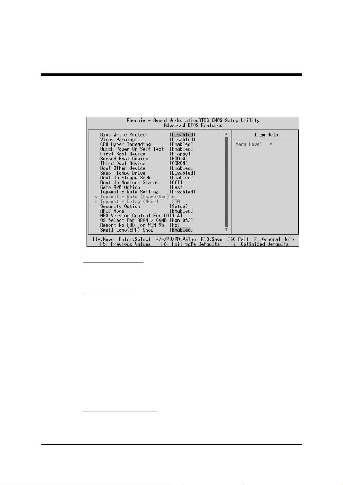
@ Advanced BIOS Features
This section allows you to configure your system for basic operation.
Bios Write Protect
This item let you enable or disable the Bios Write Protect.
Ø The choice: Enabled or Disabled.
Virus Warning
Allows you to choose the VIRUS Warning feature for IDE Hard Disk boot
sector protection. If this function is enables and someone attempts to write
data into this area, BIOS will show a warning message on screen, and an
alarm beep.
Enabled Activates automatically when the system boots up,
causing a warning message to appear when anything
attempts to access the boot sector or hard disk partition table.
Disabled No warning message will appear when anything
attempts to access the boot sector or hard disk partition table.
Ø The choice: Enabled or Disabled.
CPU Hyper-Threading
If your CPU supports the hyper-threading function, please leave this
item enabled.
Ø The choice: Enabled or Disabled.
- 57 -
Page 60

Quick Power On Self TestQuick Power On Self Test
Quick Power On Self Test
Quick Power On Self TestQuick Power On Self Test
Enable this item to shorten the power on testing ( POST ) and have your
system start up faster. You might like to this item after you are confident
that your system hardware is operating smoothly.
" The choice: Enabled or Disabled.
First/Second/Third Boot DeviceFirst/Second/Third Boot Device
First/Second/Third Boot Device
First/Second/Third Boot DeviceFirst/Second/Third Boot Device
Use these three items to select the priority and order of the devices that
your system searches for an operating system at start-up time.
" The Choice: Floppy, LS120, HDD-0, SCSI, CDROM, HDD-1, HDD-
2, HDD-3, ZIP100, USB-FDD, USB-ZIP,USB-CDRAM, USB-HDD,
LAN, or Disabled.
Boot Other DeviceBoot Other Device
Boot Other Device
Boot Other DeviceBoot Other Device
If you enable this item, the system searches all other possible locations
for and operating system if it fails to find one in the devices specified
under the First, Second, and Third boot devices.
" The choice: Enabled or Disabled.
Swap Floppy DriveSwap Floppy Drive
Swap Floppy Drive
Swap Floppy DriveSwap Floppy Drive
If you have two floppy diskette drives in your system, this item allows
you to swap the assigned drive letters so that drive A becomes drive B,
and drive B becomes drive A.
" The choice: Enabled or Disabled.
Boot Up Floppy SeekBoot Up Floppy Seek
Boot Up Floppy Seek
Boot Up Floppy SeekBoot Up Floppy Seek
If this item is enabled, it checks the size of the floppy disk drives at startup time. You don't need to enable this item unless you have a legacy
diskette drive with 360k capacity.
" The choice: Enabled or Disabled.
Boot Up NumLock StatusBoot Up NumLock Status
Boot Up NumLock Status
Boot Up NumLock StatusBoot Up NumLock Status
This item defines if the keyboard Num Lock key is active when your
system is started.
" The choice: Off or On.
Gate A20 OptionGate A20 Option
Gate A20 Option
Gate A20 OptionGate A20 Option
This item defines how the system handles legacy software that was
written for an earlier generation of processors. Leave this item at the
deafult value.
" The choice: Normal or fast.
- 58 -
Page 61

Typematic Rate SettingTypematic Rate Setting
Typematic Rate Setting
Typematic Rate SettingTypematic Rate Setting
If this item is enabled, you can use the following two items to see the
typematic rate and the typematic delay settings for your keyboard.
" The choice: Enabled or Disabled.
Typematic Rate (Chars/Sec)Typematic Rate (Chars/Sec)
Typematic Rate (Chars/Sec)
Typematic Rate (Chars/Sec)Typematic Rate (Chars/Sec)
This item sets how many times the keystroke will be repeated in a
second when you hold a key down.
" The choice: 6, 8, 10, 12, 15, 20, 24 or 30.
Typematic Delay (Msec)Typematic Delay (Msec)
Typematic Delay (Msec)
Typematic Delay (Msec)Typematic Delay (Msec)
Sets the delay time after a key is held down.
" The choice: 250, 500, 750 or 1000.
Security OptionSecurity Option
Security Option
Security OptionSecurity Option
If you have installed password protection, this item defines if the password is required at system start up, or if it is only required with a user
tries to enter the Setup Utility.
" The choice: Setup or System.
APIC ModeAPIC Mode
APIC Mode
APIC ModeAPIC Mode
This option is used to enable or disable APIC ( Advanced Programmable Interrupt Controller ) functionality. The APIC is an Intel chip that
provides symmetric multiprocessing ( SMP ) for its Pentium system.
" The choice: Enabled or Disabled.
MPS Version Control For OSMPS Version Control For OS
MPS Version Control For OS
MPS Version Control For OSMPS Version Control For OS
Selects the operating system multiprocessor support version.
" The choice: 1.1 or 1.4
OS Select For DRAM > 64MBOS Select For DRAM > 64MB
OS Select For DRAM > 64MB
OS Select For DRAM > 64MBOS Select For DRAM > 64MB
This item is only required if you have installed more than 64 MB of
memory and you are running the OS/2 operating system. Otherwise,
leave this item at the default.
" The choice: Non-OS2 or OS2.
Report No FDD For Win 95Report No FDD For Win 95
Report No FDD For Win 95
Report No FDD For Win 95Report No FDD For Win 95
If you are running a system with no floppy drive and using the
Windows 95, select " Yes " for this item to ensure compatibility with
Windows 95 logo certification.
" The choice: Yes or No.
Small Logo (EPA) ShowSmall Logo (EPA) Show
Small Logo (EPA) Show
Small Logo (EPA) ShowSmall Logo (EPA) Show
This item allows you to enable or disable the EPA Logo.
" The choice: Enabled or Disabled.
- 59 -
Page 62
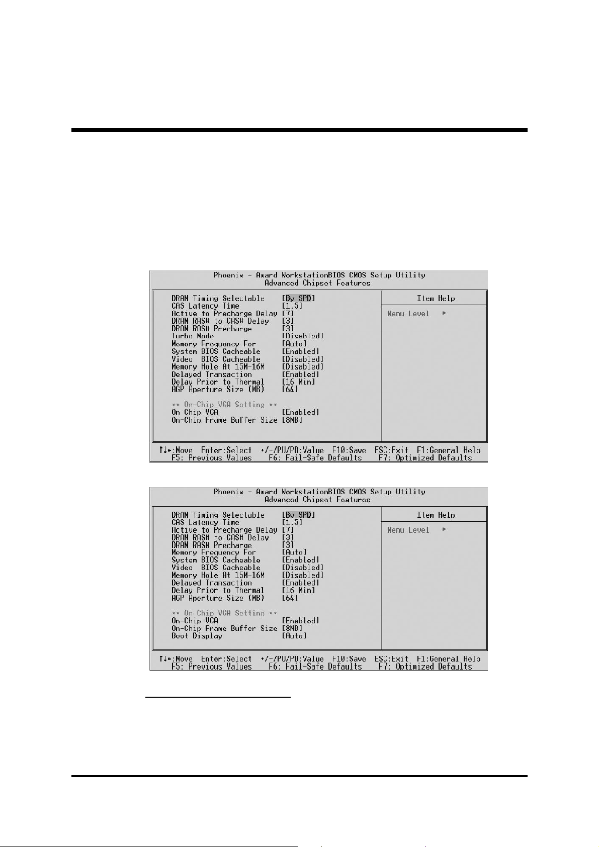
@ Advanced Chipset Features
These items define critical timing parameters of the mainboard. You should
leave the items on this page at their default values unless you are very
familiar with the technical, specifications of your system hardware. If you
change the values incorrectly, you may introduce fatal errors or recurring
instability into your system.
MB48/N
MB50/N
DRAM Timing Selectable
The value in this field depends on performance parameters of the
installed memory chips ( DRAM ). Don't change the value from the
factory setting unless you install new memory that has a different performance rating than the original DRAMs.
Ø The Choice: Manual or By SPD.
- 60 -
Page 63

CAS Latency TimeCAS Latency Time
CAS Latency Time
CAS Latency TimeCAS Latency Time
When synchronous DRAM is installed, the number of clock cycles of
CAS latency depends on the Dram timing. Don't reset this field from the
default value specified by the system designer.
" The Choice: 1.5, 2, 2.5 or 3.
Active to Precharge DelayActive to Precharge Delay
Active to Precharge Delay
Active to Precharge DelayActive to Precharge Delay
The precharge time is the number of cycles it takes for DRAM to accumulate its charge before refresh.
" The Choice: 7, 6 or 5.
DRAM RAS# to CAS# DelayDRAM RAS# to CAS# Delay
DRAM RAS# to CAS# Delay
DRAM RAS# to CAS# DelayDRAM RAS# to CAS# Delay
This field lets you insert a timing delay between the CAS and RAS
strobe signals, and you can use it when DRAM is written to, read from,
or refreshed. Faster performance is gained in high speed, more stable
performance, in low speed. This field is applied only when synchronous DRAM is installed in the system.
" The Choice: 3 or 2.
DRAM RAS# PrechargeDRAM RAS# Precharge
DRAM RAS# Precharge
DRAM RAS# PrechargeDRAM RAS# Precharge
If an insufficient number of cycles is allowed for the RAS to accumulate
its charge before DRAM refresh, the refresh may be-incompleted, and
the DRAM may fail to retain data. Fast gives faster performance; and
Slow gives more stable performance. This field is applied only
when synchronous DRAM is installed in the system.
" The Choice: 3 or 2.
Turbo ModeTurbo Mode
Turbo Mode
Turbo ModeTurbo Mode
This item allows you to enable/disable the turbo mode .
" The Choice: Enabled or Disabled.
Memory Frequency ForMemory Frequency For
Memory Frequency For
Memory Frequency ForMemory Frequency For
This item defines SDRAM frequency.
" The Choice: DDR200, DDR266, or Auto for MB48/N.
" The Choice: DDR200, DDR266, DDR333, or Auto for MB50/N.
System BIOS CacheableSystem BIOS Cacheable
System BIOS Cacheable
System BIOS CacheableSystem BIOS Cacheable
Selecting Enabled allows caching of the system BIOS ROM at F0000hFFFFFh, resulting in better system performance. However, if any program is written to this memory area, a system error may result.
" The choice: Enabled or Disabled.
(MB48/N only) (MB48/N only)
(MB48/N only)
(MB48/N only) (MB48/N only)
- 61 -
Page 64

Video BIOS CacheableVideo BIOS Cacheable
Video BIOS Cacheable
Video BIOS CacheableVideo BIOS Cacheable
Selecting Enabled allows caching of the video BIOS , resulting in better
system performance. However, if any program is written to this memory
area, a system error may result.
" The Choice: Enabled or Disabled.
Memory Hole At 15M-16MMemory Hole At 15M-16M
Memory Hole At 15M-16M
Memory Hole At 15M-16MMemory Hole At 15M-16M
You can reserve this area of system memory for ISA adapter ROM.
When this area is reserved, it can't be cached. The user information of
peripherals that need to use this area of system memory usually discusses their memory requirements.
" The Choice: Disabled or Enabled.
Delayed TransactionDelayed Transaction
Delayed Transaction
Delayed TransactionDelayed Transaction
The chipset has an embedded 32-bit posted write buffer to support
delayed transactions cycles. Enabled this item to support compliance
with PCI specification version 2.1.
" The Choice: Disabled or Enabled.
Delay Prior to ThermalDelay Prior to Thermal
Delay Prior to Thermal
Delay Prior to ThermalDelay Prior to Thermal
Enable this item to set the delay time before the CPU enters auto thermal mode.
" The Choice: 4 Min, 8 Min, 16 Min, or 32 Min.
AGP Aperture Size (MB)AGP Aperture Size (MB)
AGP Aperture Size (MB)
AGP Aperture Size (MB)AGP Aperture Size (MB)
This item defines the size of the aperture if you use an AGP graphics
adapter. The AGP aperture refers to section of the PCI memory address
range used for graphics memory. We recommend that you leave this
item at the default value.
" The Choice: 4, 8, 16, 32, 64, 128, or 256.
On-Chip VGA Setting On-Chip VGA Setting
**
On-Chip VGA Setting **
On-Chip VGA Setting On-Chip VGA Setting
On-Chip VGAOn-Chip VGA
On-Chip VGA
On-Chip VGAOn-Chip VGA
This item allows you to enable or disable On-Chip AGP.
" The Choice: Enabled or Disabled.
On-Chip Frame Buffer SizeOn-Chip Frame Buffer Size
On-Chip Frame Buffer Size
On-Chip Frame Buffer SizeOn-Chip Frame Buffer Size
This item allows you to set the VGA frame buffer size.
" The Choice: 1MB or 8MB.
Boot DisplayBoot Display
Boot Display
Boot DisplayBoot Display
This item allows you to set the VGA frame buffer size.
" The Choice: Auto,CRT,TV,EFP.
(MB50/N only) (MB50/N only)
(MB50/N only)
(MB50/N only) (MB50/N only)
- 62 -
Page 65

@ Integrated Peripherals
These options display items that define the operation of peripheral
components on the system's input / output ports.
On-Chip Primary/Secondary PCI IDE
Use these items to enable or disable the PCI IDE channels that are
integrated on the mainboard.
Ø The choice: Enabled or Disabled.
IDE Primary/Secondary Master/Slave PIO
Each IDE channel supports a master device and a slave device. These
four items let you assign which kind of PIO ( Programmed Input / Output ) is used by IDE devices. Choose Auto to let the system auto detect
which PIO mode is best or select a PIO mode from 0-4.
Ø The choice: Auto, Mode 0, Mode 1, Mode 2, Mode 3 or Mode 4.
IDE Primary/Secondary Master/Slave UDMA
Each IDE channel supports a master device and a slave device. This
mainboard supports UltraDMA technology, which provides faster
access to IDE devices.If you install a device that supports UltraDMA,
change the appropriate item on this list to Auto. You may have to install
the UltraDMA driver supplied with this mainboard in order to use an
UltraDMA device.
Ø The Choice: Auto or Disabled.
- 63 -
Page 66

USB ControllerUSB Controller
USB Controller
USB ControllerUSB Controller
Select Enabled if your system contains a Universal Serial Bus (USB) port
on this mainboard.
" The choice: Enabled or Disabled.
USB 2.0 ControllerUSB 2.0 Controller
USB 2.0 Controller
USB 2.0 ControllerUSB 2.0 Controller
Select Enabled if your system contains a Universal Serial Bus (USB) 2.0
controller and you have USB peripherals.
" The choice: Enabled or Disabled.
USB Keyboard SupportUSB Keyboard Support
USB Keyboard Support
USB Keyboard SupportUSB Keyboard Support
Select Enabled if your system contains a Universal Serial Bus (USB)
controller and you have a USB keyboard.
" The choice: Enabled or Disabled.
USB Mouse SupportUSB Mouse Support
USB Mouse Support
USB Mouse SupportUSB Mouse Support
Enabled this item if you plan to use a keyboard connected through the
USB port in a legacy operating system (such as DOS) the does not
support Plug and Play.
" The choice: Enabled or Disabled.
AC97 AudioAC97 Audio
AC97 Audio
AC97 AudioAC97 Audio
This item allows you to select AC 97 audio chip to support Audio.
Disable this item If you are going to install a PCI audio add-on card.
" The Choice: Auto or Disabled.
Init Display FirstInit Display First
Init Display First
Init Display FirstInit Display First
Use this item to specify whether your graphics adapter is installed in
one of the PCI slots or is integrated on the mainboard.
" The choice: PCI Slot or Onboard for MB48/N.
" The choice: PCI Slot or Onboard/AGP for MB50/N.
IDE HDD Block ModeIDE HDD Block Mode
IDE HDD Block Mode
IDE HDD Block ModeIDE HDD Block Mode
If your IDE hard drive supports block mode (most new drives do), select
Enabled to automatic detect the optimal number of block read and
writes per sector that the drive can support and improves the speed of
access to IDE devices.
" The choice: Enabled or Disabled.
Onboard Lan Boot ROMOnboard Lan Boot ROM
Onboard Lan Boot ROM
Onboard Lan Boot ROMOnboard Lan Boot ROM
This item allows you to enable or disable the onboard LAN Boot ROM
function.
" The Choice: Enabled or Disabled.
Onboard FDC ControllerOnboard FDC Controller
Onboard FDC Controller
Onboard FDC ControllerOnboard FDC Controller
This item specifices onboard floppy disk drive controller. This setting
allows you to connect your floppy disk drives to the onboard floppy
connector.
" The choice: Enabled Disabled.
- 64 -
Page 67

Onboard Serial Port 1/2Onboard Serial Port 1/2
Onboard Serial Port 1/2
Onboard Serial Port 1/2Onboard Serial Port 1/2
Used to assign an I/O address and interrupt request (IRQ) for the onboard serial port1/2 (COM1/2).
" The choice: Disabled, 3F8/IRQ4, 2F8/IRQ3, 3E8/IRQ4, 2E8/IRQ3, or
Auto.
UART Mode SelectUART Mode Select
UART Mode Select
UART Mode SelectUART Mode Select
Available if the onboard serial port2 is set to any option. It enables you to
select an infrared communication protocol.
" The choice: Normal, IrDA, ASKIR, or SCR.
UR2 Duplex ModeUR2 Duplex Mode
UR2 Duplex Mode
UR2 Duplex ModeUR2 Duplex Mode
Available as UART2 mode is set to either ASKIR or IrDA. It determines
the infrared function of the onboard infrared chip. Full duplex enables
you to transmit/send information simultaneously. Half one suggests data
transmitted in both directions, but only one direction at a time.
" The choice: Full or Half.
Onboard Parallel PortOnboard Parallel Port
Onboard Parallel Port
Onboard Parallel PortOnboard Parallel Port
Allows you to determine an I/O address and interrupt request (IRQ) for
the onboard parallel port.
" The choice: 378/IRQ7, 278/IRQ5, 3BC/IRQ7 or Disabled.
Parallel Port ModeParallel Port Mode
Parallel Port Mode
Parallel Port ModeParallel Port Mode
Select an operating mode for the onboard parallel port. Select Normal
or SPP unless you are certain your system supports other modes.
" The choice: SPP, EPP, ECP, or ECP+EPP.
ECP Mode Use DMAECP Mode Use DMA
ECP Mode Use DMA
ECP Mode Use DMAECP Mode Use DMA
When the parallel port mode is set to ECP, this item becomes seletable.
" The choice: 1 or 3.
PWRON After PWR-FailPWRON After PWR-Fail
PWRON After PWR-Fail
PWRON After PWR-FailPWRON After PWR-Fail
This item enables your computer to automatically restart or return to its
last operating status after power fails.
" The choice: OFF , ON or Former-Sts.
Game Port AddressGame Port Address
Game Port Address
Game Port AddressGame Port Address
This item defines an I/O address for the game port.
" The choice: Disabled, 201 or 209.
Midi Port AddressMidi Port Address
Midi Port Address
Midi Port AddressMidi Port Address
This item defines an I/O address for the MIDI port.
" The choice: Disabled, 330, or 300.
Midi Port IRQMidi Port IRQ
Midi Port IRQ
Midi Port IRQMidi Port IRQ
This item defines an interrupt request for the MIDI port.
" The choice: 5 or 10.
- 65 -
Page 68

@ Power Management Setup
The Power Management Setup allows you to configure your system to
most effectively saving energy while operating in a manner consistent
with your own style of computer use.
ACPI Function (Enabled)
This item allows you to enable the ACPI (Advanced Configuration and
Power Management ) feature.
Note: ACPI is a power management specification that makes hard-
ware status information available to the operating system. ACPI
enables a PC to turn its peripherals on or off for improving the
power management. It also allows a PC to be turned on or off
by external devices, so that a mouse or keyboard can wake up
the computer.
ACPI Suspend Type
This item allows you to select sleep state when suspend. In the default,
S1( POS ), the suspend mode is equivalent to a software power down. If
you select S3( STR ), the suspend mode is a suspend to RAM. i.e., the
system shuts down with the exception of a refresh current to the system
memory.
Ø The choice: S1(POS), S3(STR) or S1&S3.
- 66 -
Page 69

Run VGABIOS if S3 Resume (Auto)Run VGABIOS if S3 Resume (Auto)
Run VGABIOS if S3 Resume (Auto)
Run VGABIOS if S3 Resume (Auto)Run VGABIOS if S3 Resume (Auto)
Allows the system to initialize a VGA BIOS from S3 (Suspend to RAM)
sleep state.
Power ManagementPower Management
Power Management
Power ManagementPower Management
As a master switch for the power-saving mode and hard disk timeouts.
Max Saving suggests a power-saving mode occurs after a short timeout.
Min Saving implies a power-saving mode occur after a long timeout.
User Define means you can define timeouts for the power-saving mode.
" The choice: User Define, Min Saving or Max Saving.
Video Off MethodVideo Off Method
Video Off Method
Video Off MethodVideo Off Method
Determines to save power if the video is powered down.
" The choice: Blank Screen, V/H SYNC+Blank or DPMS.
Video Off In SuspendVideo Off In Suspend
Video Off In Suspend
Video Off In SuspendVideo Off In Suspend
Decides if the video turns off as the system enters a suspend mode.
" The choice: Yes or No.
Suspend TypeSuspend Type
Suspend Type
Suspend TypeSuspend Type
Defines a suspend type for your system. Stop Grant means the CPU
enters an idle mode druing a power-saving mode.
" The choice: PwrOn Suspend, Stop Grant.
MODEM Use IRQMODEM Use IRQ
MODEM Use IRQ
MODEM Use IRQMODEM Use IRQ
Defines which IRQ the modem can use.
" The choice: 3, 4, 5, 7, 9, 10, 11 or NA.
Suspend ModeSuspend Mode
Suspend Mode
Suspend ModeSuspend Mode
When enabled, all devices except the CPU will be shut off.
" The choice: Disabled, 1 Min, 2 Min, 4 Min, 8 Min, 12 Min,
20 Min, 30 Min, 40Min or 1 Hour.
HDD Power DownHDD Power Down
HDD Power Down
HDD Power DownHDD Power Down
As enabled, the hard disk drive will be powered down with other devices activized.
" The choice: Disabled or 1 Min~15 Min.
Soft-Off by PWR-BTTNSoft-Off by PWR-BTTN
Soft-Off by PWR-BTTN
Soft-Off by PWR-BTTNSoft-Off by PWR-BTTN
When set as delay for 4 seconds, pressing down the power button for
more than 4 seconds forces the system to enter the soft-off state.
" The choice: Instant-Off or Delay 4 Sec.
Wake-Up by PCI cardWake-Up by PCI card
Wake-Up by PCI card
Wake-Up by PCI cardWake-Up by PCI card
This item enables/disables the power-on function of a PCI card.
" The choice: Enabled or Disabled.
- 67 -
Page 70

Power On by RingPower On by Ring
Power On by Ring
Power On by RingPower On by Ring
Determines if the system will resume by a modem ring.
" The choice: Enabled or Disabled.
Wake Up On LANWake Up On LAN
Wake Up On LAN
Wake Up On LANWake Up On LAN
This item enables/disables a wake-up LAN function.
" The choice: Enabled or Disabled.
USB KB Wake-Up From S3USB KB Wake-Up From S3
USB KB Wake-Up From S3
USB KB Wake-Up From S3USB KB Wake-Up From S3
Awaken the system by a USB keyboard as enabled. As ACPI suspend
type enters S1(POS), this item becomes unselectable and disabled.
" The choice: Enabled or Disabled.
Resume by AlarmResume by Alarm
Resume by Alarm
Resume by AlarmResume by Alarm
When enabled, set the date and time of the RTC (Real-Time Clock)
alarm will awaken the system from a suspend mode.
" The choice: Disabled or Enabled.
Data (of Month) AlarmData (of Month) Alarm
Data (of Month) Alarm
Data (of Month) AlarmData (of Month) Alarm
This item selects the alarm date.
" Key in a DEC number: Min=0, Max=31.
Time (hh:mm:ss) AlarmTime (hh:mm:ss) Alarm
Time (hh:mm:ss) Alarm
Time (hh:mm:ss) AlarmTime (hh:mm:ss) Alarm
This item selects the alarm time.
[hh] " Key in a DEC number: Min=0, Max=23.
[mm/ss] " Key in a DEC number: Min=0, Max=59.
** Reload Global Timer Events **** Reload Global Timer Events **
** Reload Global Timer Events **
** Reload Global Timer Events **** Reload Global Timer Events **
Global Timer (power management) events are I/O events whose occurrence can prevent the system from entering a power-saving mode, or
can awaken the system from such a mode. The system stays alert as a
device is enabled, even as the system is in a power-down mode.
Primary/Secondary IDE 0/1Primary/Secondary IDE 0/1
Primary/Secondary IDE 0/1
Primary/Secondary IDE 0/1Primary/Secondary IDE 0/1
As enabled, the system will restart when any activity is detected from
drives or devices on the primary or secondary IDE channels.
" The choice: Disabled or Enabled.
FDD, COM, LPT PortFDD, COM, LPT Port
FDD, COM, LPT Port
FDD, COM, LPT PortFDD, COM, LPT Port
As enabled, the system will restart when any activity is detected from
the floppy disk drive, serial ports, or the parallel port.
" The choice: Disabled or Enabled.
PCI PIRQ [A-D]#PCI PIRQ [A-D]#
PCI PIRQ [A-D]#
PCI PIRQ [A-D]#PCI PIRQ [A-D]#
As disabled, any PCI device set as Master will not power on the system.
" The choice: Disabled or Enabled.
- 68 -
Page 71

@ PNP/PCI Configurations
This category configures how PnP and PCI operate in your system.
Correctly setting up the IRQ and DMA (both PnP and PCI use) assignments will make your system work stably. It is strongly recommended
that only technical users make changes to the default settings.
Reset Configuration Data
When enabled, any PnP configuration data stored in the BIOS will be
cleared from memory, with new data created.
Ø The choice: Enabled or Disabled.
Resource Controlled By
As stays auto(ESCD), the system will dynamically allocate resources to
PnP devices as they are required. As set to manual, the following item
become available.
Ø The choice: Auto(ESCD) or Manual.
IRQ Resources
When the previous item is set to manual, this item allows you respectively assign an interruptive type for IRQ-3, 4, 5, 7, 9, 10, 11, 12, 14,
and 15.
Ø The choice: PCI Device or Reserved.
PCI/VGA Palette Snoop
The item is designed to solve problems caused by some non-standard
VGA cards. A built-in VGA system does not need this function.
Ø The choice: Enabled or Disabled .
INT Pin 1~5 Assignment
Names the interrupt request (IRQ) line assigned to a device connected
to the PCI interface on your system.
Ø The Choice: Auto, 3, 4, 5, 7, 9, 10, 11, 12, 14, 15.
- 69 -
Page 72

@ PC Health Status
Shutdown Temperature
Enables you to set the maximum temperature the system can reach
before powering down.
Ø The choice: 60°C/140°F, 65°C/149°F, 70°C/158°F, or 75°C/
167°F.
The following items provide you with information about the current
operating status on your system. You cannot make any changes to one
of them, including:
CPU Vcore Fan 1 Speed
VDDQ Fan 2 Speed
+3.3V Fan 3 Speed
+5V
+12V
-12V
+5VSB
Voltage Battery
System Temperature
CPU Temperature
PWM Temperature
- 70 -
Page 73

@ Frequency/Ratio Control
CPU Clock Ratio
The item defines a multiplier for the system FSB frequency. The formula
is presented as follows:
Multiplier X FSB Frequency = CPU Clock Speed
For example, a processor at 450MHz and FSB frequency at 100MHz
ought to set the multiplier at 4.5 for: 4.5 (Multiplier) X 100MHz (FSB
Frequency) = 450MHz (CPU Clock Speed).
Ø Key in a DEC number: Min=8, Max=50.
Auto Detect PCI Clk
When enabled, the BIOS will disable the clock signal of the free PCI
slots.
Ø The choice: Enabled or Disabled.
Spread Spectrum
This item can reduce the EMI (Electro-Magnetic Interference) generated
by the system.
Ø The choice: Disabled or Enabled.
CPU Clock
This item allows users to adjust the CPU host clock from 100MHz to
165MHz.
Ø Key in a DEC number: Min=100, Max=165.
- 71 -
Page 74

@ Load Fail-Safe Defaults
When you press <Enter> on this item, you will see a dialog box with a
message similar to:
Load Fail-Safe Defaults (Y/N)? N
Press <Y> and <Enter> to install the defaults, and v.v.
@ Load Optimized Defaults
When you press <Enter> on this item, you will see a dialog box with a
message similar to:
Load Optimized Defaults (Y/N)? N
Press <Y> and <Enter> to install the defaults, and v.v.
@ Set Supervisor/User Password
Steps to set supervisor/user password are described as follows:
New Password Setting:
1. While pressing <Enter> to set a password, a dialog box appears to
ask you enter a password.
2. Key in a new password. The password can not exceed eight charac-
ters.
3. System will request you to confirm the new password again.
4. When completed, new code takes effect.
- 72 -
Page 75

No Password Setting:No Password Setting:
No Password Setting:
No Password Setting:No Password Setting:
If you want to disable the password, just press <Enter> as a password
input is requested.
If You Forget Password:If You Forget Password:
If You Forget Password:
If You Forget Password:If You Forget Password:
If you forget the password, the only way to access the system is to clear
the CMOS memory. Please refer to page 26 on clear CMOS setting.
!!
! Save & Exit Setup
!!
When you press <Enter> on this item, you will see a dialog box with a
message similar to:
Press <Y> to save the changes you have made in the Setup Utility and
exit, or press <N> to return to the main menu.
!!
! Exit Without Saving
!!
Save to CMOS and EXIT (Y/N)? Y
When you press <Enter> on this item, you will see a dialog box with a
message similar to:
Quit Without Saving (Y/N)? N
Press <Y> to discard the changes you have made in the Setup Utility and
exit, or press <N> to return to the main menu.
- 73 -
 Loading...