


MB47N
Pentium 4/Celeron, 478-Pin Processor
Based MAIN BOARD
User's Manual

Shuttle® MB47N
Pentium 4/Celeron,478-pin processor based Mainboard
Manual Version 1.1
Copyright
Copyright© 2002 by Shuttle® Inc. All Rights Reserved.
No part of this publication may be reproduced, transcribed, stored in a retrieval system,
translated into any language, or transmitted in any form or by any means, electronic,
mechanical, magnetic, optical, chemical, photocopying, manual, or otherwise, without
prior written permission from Shuttle
®
Inc.
Disclaimer
Shuttle® Inc. shall not be liable for any incidental or consequential damages resulting
from the performance or use of this product.
This company makes no representations or warranties regarding the contents of this
manual. Information in this manual has been carefully checked for reliability; however,
no guarantee is given as to the correctness of the contents. In the interest of continued
product improvement, this company reserves the right to revise the manual or include
changes in the specifications of the product described within it at any time without notice
and without obligation to notify any person of such revision or changes. The information
contained in this manual is provided for general use by the customers.
Trademarks
Shuttle is a registered trademark of Shuttle Inc.
Intel, Pentium is a registered trademarks of Intel Corporation.
PS/2 is a registered trademark of IBM Corporation.
AWARD is a registered trademark of Award Software Inc.
Microsoft and Windows are registered trademarks of Microsoft Corporation.
General Notice: Other brand and product names used herein are for identification
purposes only and may be trademarks of their respective owners.
M584

- 1 -
1 INTRODUCTION ................................................................................. 4
1.1 ITEM CHECKLIST ........................................................................................4
2 FEATURES.......................................................................................... 5
2.1 SPECIFICATIONS ........................................................................................ 5
3 HARDWARE INSTALLATION ............................................................. 8
3.1 STEP BY STEP INSTALLATION .................................................................. 8
Accessories of MB47N............................................................................ 8
STEP 1 Install the CPU ............................................................................. 9
STEP 2 Set Jumpers .............................................................................. 11
STEP 3 Install DDR SDRAM System Memory ........................................ 11
STEP 4 Install Peripherals in System Case ............................................ 12
STEP 5 Mount the Mainboard on the Computer Chassis ....................... 13
STEP 6 Connect Front Panel Switches/LEDs/Speaker/USB/AUDIO1 ... 14
STEP 7 Connect IDE and Floppy Disk Drives......................................... 16
STEP 8 Connect Other Internal Peripherals ........................................... 16
STEP 9 Connect the Power Supply........................................................ 17
STEP 10 Install Add-on Cards in Expansion Slots .................................. 17
STEP 11 Connect External Peripherals to Back Panel ...........................18
STEP 12 Install Drivers & Software Components ...................................19
3.2 JUMPER SETTINGS .................................................................................. 20
JUMPERS & CONNECTORS GUIDE .................................................... 21
Jumpers
Clear CMOS Setting (JP1) .................................................................... 24
BIOS Flash Protecion Setting (JP3)............................................................... 24
LAN Select on Board Setting(JP4) ................................................................ 25
Core Voltage Select Jumper Setting(VID4~VID0)........................................ 25
TABLE OF CONTENTS

- 2 -
Back-Panel Connectors
PS/2 Keyboard & PS/2 Mouse Connectors ............................................ 27
LAN Port Connector ............................................................................... 27
USB0/USB1 Port Connectors ................................................................. 27
COM Port Connector ..............................................................................27
VGA Port Connector ....................................................................................... 28
Parallel Port Connector ...........................................................................28
Line-Out Port Connector ......................................................................... 28
Line-In Port Connector ............................................................................ 28
Mic-In Port Connector ............................................................................. 28
GAME/MIDI Port Connector ....................................................................28
Front-Panel Connectors
Speaker Connector (SPEAKER) ............................................................ 30
Panel1 Connector ............................................................................................ 30
Audio1 Connector ............................................................................................ 31
Extend USB Header (USB2/USB3) ............................................................... 31
Internal Peripherals Connectors
Enhanced IDE and Floppy Connector .................................................... 32
Other Connectors
ATX Power Supply Connector (ATX1 and ATX12V) ................................ 33
CPU, Power, CAS Fan connectors ............................................................... 34
IR Header ............................................................................................... 34
Wake-on Modem Connector (WOM1) ........................................................... 35
Wake-on LAN Connector (WOL1) ................................................................ 35
Audio CD-IN1/2 Connector ..................................................................... 35
3.3 SYSTEM MEMORY CONFIGURATION ......................................................36
1. INSTALL MEMORY............................................................................. 36

- 3 -
2. UPGRADE MEMORY ......................................................................... 36
4 SOFTWARE UTILITY .......................................................................3 7
4.1 Mainboard CD Overview ...........................................................................37
4.2 The mainboard Software Driver ............................................................... 38
4.3 Install INTEL INF Driver .............................................................................39
4.4 Install IDE Driver .......................................................................................40
4.5 Install VGA Driver...................................................................................... 41
4.6 Install Audio Device Driver ....................................................................... 42
4.7 Install LAN Driver .......................................................................................43
4.8 View the User's Manual............................................................................. 49
5 BIOS SETUP .....................................................................................50
5.1 ENTER BIOS .............................................................................................. 50
5.2 THE MAIN MENU .......................................................................................51
STANDARD CMOS FEATURES ................................................................ 53
ADVANCED BIOS FEATURES .................................................................. 55
ADVANCED CHIPSET FEATURES ........................................................... 58
INTEGRATED PERIPHERALS ................................................................... 61
POWER MANAGEMENT SETUP .............................................................. 66
PNP/PCI CONFIGURATION ....................................................................... 70
PC HEALTH STATUS ................................................................................. 72
FREQUENCY/VOLTAGE CONTROL ..........................................................74
LOAD FAIL-SAFE DEFAULTS ................................................................... 75
LOAD OPTIMIZED DEFAULTS .................................................................. 75
SET SUPERVISOR/USER PASSWORD ................................................... 76
SAVE & EXIT SETUP................................................................................. 78
EXIT WITHOUT SAVING ............................................................................. 78

- 4 -
1.1 Item Checklist:
Check all items with you MB47N mainboard to make sure nothing is missing. The complete package should include:
! One piece of Shuttle MB47N Mainboard
! One piece of ATA
100 /66/33100 /66/33
100 /66/33100 /66/33
100 /66/33 Ribbon Cable
! One piece of Floppy Ribbon Cable
! One piece of twin ports USB Cable
(optional)(optional)
(optional)(optional)
(optional)
! MB47N User's Manual
! I/O Shielding
! One piece of Bundled CD-ROM with containing:
" MB47N user's manual saved in PDF format
" Intel Chipset System Driver
" Onboard Audio controller driver
" IDE driver
" USB2.0 Driver
" VGA driver
" Award Flashing Utility
1 INTRODUCTION
1
RTL8100B
2103OS1
2031TAIWAN
RMC
SEC
RET
FW82801DB
L204TB4Q
QC97ES
INTEL Q1
C
G146949
7TD
204 KOREA
e
C
PhoenixBiosTM
D688 BIDS
PHOENIX 1
998
071776060
K
TS1
4.3
E2j
I R
IRU101
0
P
C
N
E
T
H
t2
00
1
02
03
PSKBM1
A
T
X
1
CNRI
PCI3
PCI2
PCI1
WOM1WOL1
I R 1
USB 2
U
S
B
3
FDD1
JP3
C
A
S
F
A
N
1
L
S
J
1
S
j
1
IDE2
IDE1
CPU
FAN1DIMM2
DIMM2

- 5 -
MB47N mainboard is carefully designed for the demanding PC user who wants high
performance and maximum intelligent features in a compact package.
2.1 Specifications
!!
!!
! CPU Support
Intel Pentium 4/Celeron, 478-pin processors with 400 MHz FSB.
!!
!!
! Chipset
Features Intel 845-GL (GMCH) and Intel 82801DB (ICH4).
!!
!!
! Onboard 10/100M LAN
The Realtek RTL8100B is incorporated in the chipset providing the
mainboard with integrated Fast Ethernet capabilities.
!!
!!
! Jumperless CPU Configuration
Supports 400MHz (FSB) and data bandwidths up to 3.2GB/s.
!!
!!
! AC'97 Link for 4-Channel Audio and Telephony CODEC
AC'97 audio codec is compliant with the AC'97 2.3 specification, and
supports 18-bit ADC ( Analog Digital Converter) and DAC (Digital Analog
Converter) resolution as well as 18-bit stereo full-duplex codec with independent and variable sampling rates.
!!
!!
! Versatile Memory Support
The mainboard can accommodate 2.5V unbuffered DDR SDRAM. It accommodates two 184 pin slots with a total maximum capacity of 2GB.
!!
!!
! Expansion Slots
Provides three 32-bit PCI card slots and on CNR slot.
!!
!!
! USB2.0 Interface Onboard
" 2 USB ports on back-panel and two USB header (4 ports) for extended USB
cable and front-panel.
2 FEATURES

- 6 -
!!
!!
! I/O Interface
Provides a variety of I/O interfaces:
" 2PS/2 ports for mouse and keyboard
" 1Parallel port
" 1Serial port
" 1VGA port
" 1MIDI/GAME port.
" 1LAN port
" 2USB ports
" 1Mic-in port
" 1Line-in port
" 1Line-out port
!!
!!
! PCI Bus Master IDE Controller Onboard
Two Ultra DMA 100/66/33 Bus Master Dual-channel IDE ports support to a
maximum of four IDE devices (one Master and one Slave per channel).
The IDE Bus implements data transfer speeds of up to 100 MB/sec and also
supports Enhanced PIO Modes.
80-pin Cable Backward Compatible Legacy ATAPI Devices, ATAPI IDE CDROM, CD-R, CD-RW, and LS-120 Supports.
!!
!!
! ATX Power Supply Connector
ATX power supply unit can connected to the onboard 20-pin Pentium 4
standard ATX power connectors, supporting Suspend and Soft-On/Off by
dual-function power button.
The Pentium 4 ATX power include two connectors.
!!
!!
! Advanced Configuration and Power Interface
Features four power saving modes: S1 (Snoop), S3 (Suspend to RAM), S4
(Suspend to DISK), and S5 (Soft-Off). ACPI provides more efficient Energy
Saving Features controlled by your operating system that supports OS Direct
Power Management (OSPM) functionality.
!!
!!
! System BIOS
Provides licensed Award BIOS V6.0 PG on Intel Firmware Hub 2Mb Flash
core and supports Green PC, Desktop Management Interface (DMI).

- 7 -
!!
!!
! Form Factor
System board conforms to Micro ATX specification.
Board dimension: 244mm x 244mm.
!!
!!
! Advanced Features
"
Low EMI -Low EMI -
Low EMI -Low EMI -
Low EMI - Built in spread spectrum and automatic clock shut-off of
unused PCI/SDRAM slots to reduce EMI.
"
Dual Function Power Button - Dual Function Power Button -
Dual Function Power Button - Dual Function Power Button -
Dual Function Power Button - The system can be in one of two states,
one is Suspend mode and the other is Soft-Off mode. Pushing the power
button for less than 4 seconds places the system into Suspend mode.
When the power button is pressed for longer than 4 seconds, the system
enters Soft-Off mode.
"
Modem Ring Power-On - Modem Ring Power-On -
Modem Ring Power-On - Modem Ring Power-On -
Modem Ring Power-On - The system can be powered on automatically
by the activation of modem ringing.
"
CPU Clock SettingCPU Clock Setting
CPU Clock SettingCPU Clock Setting
CPU Clock Setting - This item allows users to adjust CPU Host Clock in
BIOS.
"
CPU Multiplier SettingCPU Multiplier Setting
CPU Multiplier SettingCPU Multiplier Setting
CPU Multiplier Setting - This item allows users to adjust CPU Multiplier
in BIOS.
"
CPU Vcore SettingCPU Vcore Setting
CPU Vcore SettingCPU Vcore Setting
CPU Vcore Setting - This item allows users to select the CPU Vcore by
jumper.
!!
!!
! Intelligent Features
"
Voltage Monitoring -Voltage Monitoring -
Voltage Monitoring -Voltage Monitoring -
Voltage Monitoring - Monitors various voltages of key elements, such as
the CPU, and other critical system voltage levels to ensure stable current
passing through mainboard components.
"
Fan Status MonitoringFan Status Monitoring
Fan Status MonitoringFan Status Monitoring
Fan Status Monitoring
--
--
- To prevent CPU from overheating, the CPU fan is
monitored for RPM and failure. (CPU Cooling FAN with RPM sensor is
required.)
"
Temperature Monitoring -Temperature Monitoring -
Temperature Monitoring -Temperature Monitoring -
Temperature Monitoring - This item allows users to make sure whether the
CPU or system runs in a suitable temperature.

- 8 -
Before removing or installing any of these devices including CPU, DIMMs, Add-OnBefore removing or installing any of these devices including CPU, DIMMs, Add-On
Before removing or installing any of these devices including CPU, DIMMs, Add-OnBefore removing or installing any of these devices including CPU, DIMMs, Add-On
Before removing or installing any of these devices including CPU, DIMMs, Add-On
Cards, Cables, please make sure to unplug the onboard power connector.Cards, Cables, please make sure to unplug the onboard power connector.
Cards, Cables, please make sure to unplug the onboard power connector.Cards, Cables, please make sure to unplug the onboard power connector.
Cards, Cables, please make sure to unplug the onboard power connector.
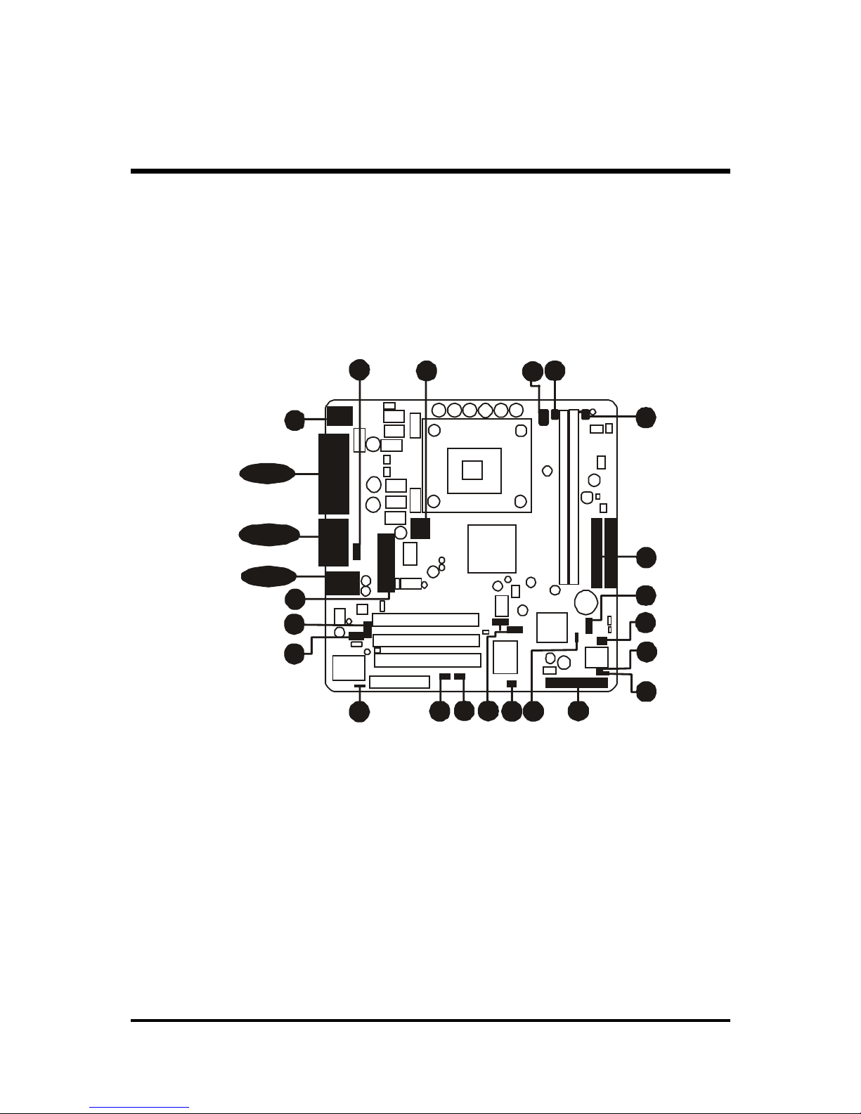
This section outlines how to install and configure your mainboard. Refer to the following
mainboard layout to help you to identify various jumpers, connectors, slots, and ports.
Then follow these steps designed to guide you through a quick and correct installation of
your system.
3.1 Step-by-Step Installation
3 HARDWARE INSTALLATION
Accessories Of MB47N
1
RTL81 00B
21 03 OS 1
2031 TAIWA N
RMC
SECRET
FW82801DB
L204TB4Q
QC97ES
INTEL Q1
+
G1469497TD
204 KOREA
e
+
PhoenixBios
TM
D688 BIDS
PHOENIX 1998
071776060
K
T
S
1
4
.3
E
2
j
I R
IRU1010
P
C
N
E
T
H
t
2
0
0
1
0
2
0
3
PSKBM 1
A
T
X
1
CNRI
PCI3
PCI2
PCI1
WOM1 WOL1
I R 1
USB 2
U
S
B
3
FDD1
JP 3
C
A
S
F
A
N
1
L
S
J
1
S
j
1
IDE2
IDE1
CPU FAN1
DIMM2DIMM2
Three PCI Slots
SOCK ET 478
ATX 12V
Select onboard
LA N - JP 4
CNR 1
IR 1
Wake On Ring
- WOM 1
C
P
U
F
A
N
4
USB & LAN Connectors
Wake On LAN
- WO L1
Parallel Connector
Serial Port
Connector
VGA Port
CDIN 2
CDIN 1
Line-Out/Line-In
/Mic-In/Game/MIDI
Connectors
PS/2 Keyboard and
PS/2 Mouse Connectors
ATX 1
Au di o 1
Two DIMM Slots
VID4 - V ID 0
PWR FAN 1
P
A
N
E
L
1
B
I
O
S
f
l
a
s
h
p
r
o
t
e
c
t
j
u
m
b
e
r
-
J
p
3
C
A
S
F
A
N
1
I
n
t
e
l
8
2
8
0
1
D
B
S
P
E
A
K
E
R
1
Clea r CM OS Ju m p er - JP 1
Flo ppy Connector
T
w
o
I
D
E
C
o
n
n
e
c
t
o
r
s
I
n
t
e
l
8
4
5
-
G
C
h
i
p
s
e
t
- 9 -
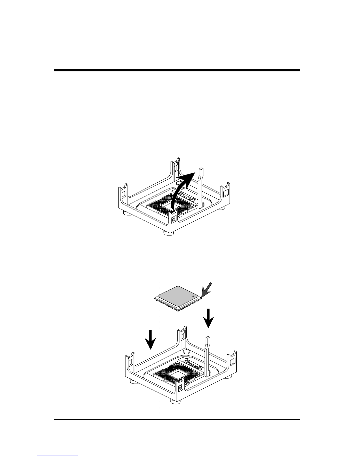
Step 1
CPU Installation:
This mainboard supports Intel Pentium 4/Celeron , Socket 478 series CPU.
Please follow the step as below to finish CPU installation.
Be careful of CPU orientation when you plug it into CPU socket.
1. Pull up the CPU socket level and up to 90-degree angle.
2. Locate Pin 1 in the socket and look for a black dot or cut edge on the CPU
upper interface. Match Pin 1 and cut edge, then insert the CPU into the
socket.
CPU pin 1 and cut edge
CPU socket level up to
90 degree

- 10 -
3. Press down the CPU socket level and finish CPU installation.
Note:Note:
Note:Note:
Note: If you do not match the CPU socket Pin 1 and CPU cut
edge well, it may damage the CPU.

- 11 -
Step 2.
Set Jumpers
The default jumper settings have been set for the common usage standard of
this mainboard. Therefore, you do not need to reset the jumpers unless you
require special adjustments as any of the following cases:
1. Clear CMOS
2. BIOS Protect
3. LAN Select
4. CPU Core Voltage Select
For first-time DIY system builders, we recommend that you do not change the
default jumper settings if you are not totally familiar with the mainboard
configuration procedures. The factory-set default settings are tuned for optimum system performance. For the advanced users who wish to customize
their system, section
3.2 Jumper Settings3.2 Jumper Settings
3.2 Jumper Settings3.2 Jumper Settings
3.2 Jumper Settings will provide detail information on
how to configure your mainboard manually.
Step 3
Install DDR SDRAM System Memory
To install memory, insert DDR SDRAM memory module(s) in any one or two
DIMM banks. Note that DDR SDRAM modules are directional and will not
go in the DIMM banks if they are not properly oriented. After the module is
fully inserted into the DIMM bank, lift the clips of both sides of the DIMM
bank to lock the module in place.

- 12 -
Step 4
Install Internal Peripherals in System Case
Before you install and connect the mainboard into your system case, we
recommend that you first assemble all the internal peripheral devices into the
computer housing, including but not limited to the hard disk drive (IDE/
HDD), floppy disk drive (FDD), CD-ROM drive, and ATX power supply unit.
This will greatly facilitate in connecting to the mainboard described below.
To install IDE & FDD drives, follow this procedure:
1. Set the required jumpers on each device according to the instructions
provided by the manufacturer. (IDE devices, HDD, and CD-ROM have to
set jumpers to Master or Slave mode depending on whether you install
more than one device of each kind.)
2. Connect IDE cable and FDD cable on the back-panel of the internal
peripheral devices to the corresponding headers on board. Note that the
cable should be oriented with its colored stripe (usually red or magenta)
connected to pin#1 both on the mainboard IDE or FDD connector and on
the device as well.
3. Connect an available power cable from your system power supply unit
to the back-panel of each peripheral device. Note that the power cable is
directional and cannot fit in if not properly positioned.
- 13 -
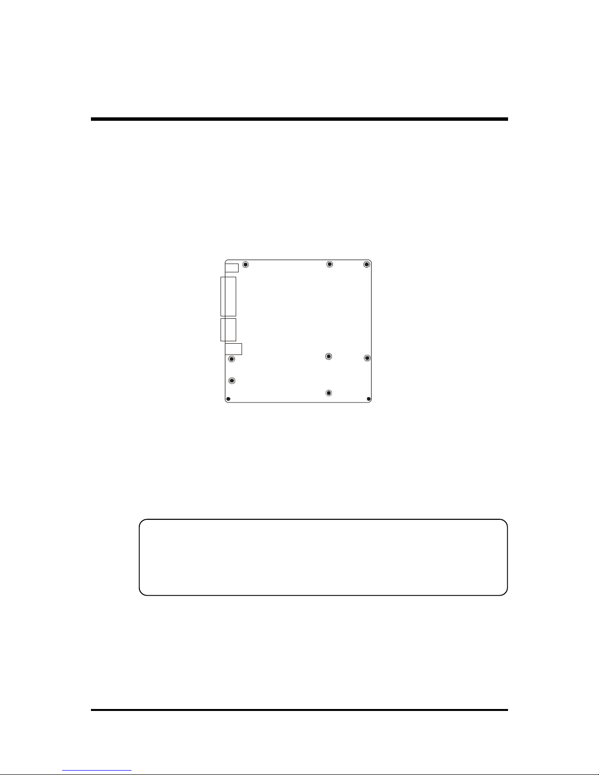
Step 5
Mount the Mainboard on the Computer Chassis
1. You may find that there are a lot of different mounting hole positions
both on your computer chassis and on the mainboard. To choose
correct mounting holes, the key point is to keep the back-panel of the
mainboard in a close fit with your system case, as shown below.
2. After deciding on the proper mounting holes, position the studs between
the frame of the chassis and the mainboard. The studs are used to fix the
mainboard and to keep a certain distance between the system chassis and
the mainboard, in order to avoid any electrical shorts between the board
and the metal frame of the chassis.
(If your computer case is already equipped with mounting studs, you will
need to tighten screws to attach the (mainboard.)
Note:Note:
Note:Note:
Note:In most computer housings, you will be able to find 4 or more attach ment points to install mounting studs and then fix the mainboard. If
there aren't enough matching holes, then make sure to install at least
4 mounting studs to ensure proper attachment of the mainboard.
- 14 -
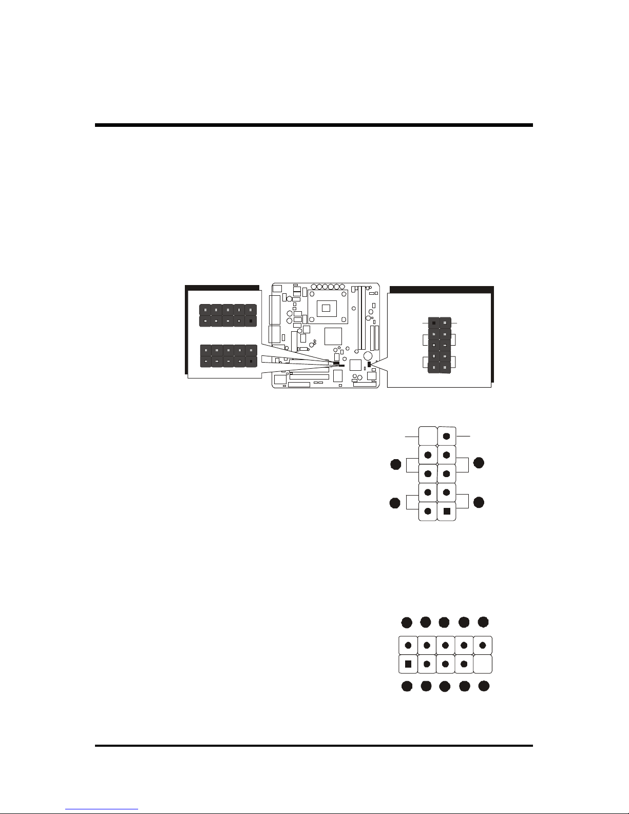
Step 6
Connect Front Panel Switches/LEDs/Speaker/USB/AUDIO1
You can find there are several different cables already existing in the system
case and originating from the computers front-panel devices (HDD LED,
Power LED, Reset Switch, PC Speaker, or USB devices etc.) These cables
serve to connect the front-panel switches, LEDs, and USB connectors to the
mainboard’ front-panel connectors group ( PANEL1, USB2/3, SPEAKER1,
AUDIO1), as shown below.
1. HDD LED
2. Green LED Indicator
3. Reset Switch
4. Power ON/OFF
5. VCC
6. USBP4 -
7. USBP4+
8. GROUND
9. KEY
10. USBPWR 1
11. USBP5 -
12. USBP5+
13. GROUND
14. NC
1
USB 2
1
USB 3
1
HDD LED
Green
LED
Power
ON/OFF
Reset
Switch
N / CEmpty
PANEL 1
USB 2
#
%
$
&
!
'
"
V
C
C
U
S
B
P
4
-
U
S
B
D
4
+
G
R
O
U
N
D
K
E
Y
U
S
B
P
W
R
1
U
S
B
P
5
-
U
S
B
P
5
+
G
R
O
U
N
D
N
C
1
Empty
Green
LED
Power
Switch
HDD L ED
Re set
Switch
N/C
1
!
"
PANEL1

- 15 -
15. VCC
16. USBP2 -
17. USBP2+
18. GROUND
19. KEY
20. USBPWR1
21. USBP3 -
22. USBP3+
23. GROUND
24. NC
SPEAKER1
1. SIGNAL
2. KEY
3. Ground
4. VCC
AUDIO 1
1. MICIN
2. AGND
3. MICBIAS
4. 5V
5. SPKOUTR
6. XSPKOUTR
7. KEY
8. EMPTY
9. SPKOUTL
10.XSPKOUTL
1
SPEAKER 1
4 3 2 1
AUDIO1
1
1
3
5
7
9
2
4
6
8
10
1
USB 3
#
%
$
& !'
"
V
C
C
U
S
B
P
2
-
U
S
B
D
2
+
G
R
O
U
N
D
K
E
Y
U
S
B
P
W
R
1
U
S
B
P
3
-
U
S
B
P
3
+
G
R
O
U
N
D
N
C

- 16 -
CD-IN 1
CD-IN 2
Step 7
Connect IDE and Floppy Disk Drives
1. IDE cable connector
2. Floppy cable connector
Step 8
Connect Other Internal Peripherals
1. CD-IN1/CD-IN2 connectors
1
FDDI
IDE1IDE2
1
11

- 17 -
Step 9
Connect the Power Supply
1. System power connector
Step 10
Install Add-on Cards in Expansion Slots
1. PCI Card
2. CNR Card
ATX 12V
ATX 1

- 18 -
Step 11
Connect External Peripherals to Back-Panel
You are now ready to put the computer case back together and get on to the
external peripherals connections to your system back-panel.
1. PS/2 Mouse and PS/2 Keyboard
2. Parallel Port
3. COM Port
4. VGA Port
5. MIDI/GAME Port
6. Audio Line-Out /Mic-In / Line-In Ports
7. LAN Port
8. USB Ports0 /1
foxconn
!
"
%
$
&
#

- 19 -
Step 12
Install Drivers & Software Components
Please note that all the system utilities and drivers are designed for Win 9x/
2000/ME/NT operating systems only. Make sure your operating system is
already installed before running the drivers installation CD-ROM programs.
1. Insert the MB47N bundled CD-ROM into your CD-ROM drive. The
auto-run program will display the drivers main installation window on
screen.
2. Choose "Install Chipset System Driver" and complete it.
3. Choose "Install Intel Ultra ATA Driver" and complete it.
4. Choose "Install Intel USB2.0 Driver" and complete it.
5. Choose "Install Audio Driver" and complete it.
6. Choose "Install LAN Driver" and complete it.
7. Exit from the auto-run drivers installation program.
# Please refer to section
Chapter 4 Software UtilityChapter 4 Software Utility
Chapter 4 Software UtilityChapter 4 Software Utility
Chapter 4 Software Utility to install LAN driver.

- 20 -
3.2 Jumper Settings
Several hardware settings are made through the use of mini jumpers to connect jumper pins on the mainboard. Pin #1 could be located at any corner of
each jumper, you just find the location with a white right angle which stands
for pin 1#. There are several types of pin 1# shown as below:
3-pin and multi (>3) pin jumpers shown as following:
Pin #1 to the left:
Pin #1 on the top:
Pin #1 to the right:
Pin #1 on the bottom:
Jumpers with two pins are shown as for Close [On] or for
Open [Off]. To Short jumper pins, simply place a plastic mini jumpers over
the desired pair of pins.
Caution!Caution!
Caution!Caution!
Caution!
1. Do not remove the mainboard from its antistatic protective packaging
until you are ready to install it.
2. Carefully hold the mainboard by its edges and avoid touching its
components. When putting the mainboard down, place it on top of its
original packaging film, on an even surface, and components side up.
3. Wear an antistatic wrist strap or take other suitable measures to prevent
electrostatic discharge (ESD) whenever handling this equipment.
- 21 -
Jumpers&Connectors Guide
Use the mainboard layout on page 11 to locate CPU socket, memory banks,
expansion slots, jumpers and connectors on the mainboard during the installation. The following list will help you to identify jumpers, slots, and connectors along with their assigned functions:
CPU/Memory/Expansion Slots
Socket478 : CPU Socket for Pentium4 /Celeron, 478-pin processors
DIMM1/2 : Two DIMM Slots for 128, 256, 512 MB, and 1GB of 2.5V
DDR SDRAM
(The total installed memory does not exceed 2GB)
PCI : Three 32-bit PCI Expansion Slots
CNR : One Communication and Networking Riser Slot
B7~B 10
B4~B 6
B2~B 3
B1
D1
C2
E2
E2
E2
A4
A2
C1
D1C4
A1
E1
C3
E3E4
E5
E7
E6
E1
A3

- 22 -
Jumpers
JP1 : Clear CMOS setting
JP3 : BIOS flash protect jumper
JP4 : Select onboard LAN
VID4~VID0 : CPU Core voltage selector jumper
Back Panel Connectors
KB : PS/2 keyboard port
MS : PS/2 mouse port
LAN : RJ45 LAN Port
USB : 2 USB (Universal Serial Bus) ports
COM1 : Serial ports 1
VGA Port : VGA port
PRINTER : Parallel port
LINE_OUT : Line-Out port
LINE_IN : Line-In port
MIC_IN : Mic-In port
GAME/MIDI : GAME/MIDI Port
Front Panel Connectors
SPEAKER : Internal speaker in housing
PANEL1 : PANEL connector
AUDIO1 : Front-Panel MIC/Speaker Out header
USB2/3 : Front panel USB ports connector
Internal Peripherals Connectors
FDD1 : Floppy disk drive interface
IDE1 : IDE primary interface (Dual-channel)
IDE2 : IDE secondary interface (Dual-channel)
Other Connectors
ATX1/ATX12V : ATX power connector
CPUFAN : CPU fan connector
PWRFAN : Power fan connector
)
*
*
*!
*"
*
*#
*$
*%
*&
+
,
,
,
*'
)
)!
-
-
-
)"
*
*
+
+!
+"

- 23 -
CASFAN : Chassis fan connector
IR1 : Infrared cable header
WOM1 : Wake On Modem wake up connector
WOL1 : Wake On LAN wake up connector
CDIN1 : CD_IN connector(WHITE), Panasonic Type
CDIN2 : CD_IN connector(BLACK), Sony Type
-$
-%
-
-"
-!
-#

- 24 -
$$
$$
$ Jumpers
Clear CMOS Setting (JP1)
JP1 is used to clear CMOS data. Clearing CMOS will result in the permanently erasing previous system configuration settings and the restoring original (factory-set) system settings.
Pin 1-2 (Default)
Pin 2-3 (Clear CMOS)
Step 1.Step 1.
Step 1.Step 1.
Step 1. Turn off the system power (PC-> Off).
Step 2.Step 2.
Step 2.Step 2.
Step 2. Remove ATX Power cable from ATX Power connector.
Step 3.Step 3.
Step 3.Step 3.
Step 3. Remove jumper cap from JP1 pins 1-2.
Step 4.Step 4.
Step 4.Step 4.
Step 4. Place the jumper cap on JP1 pin 2-3 for a few seconds.
Step 5.Step 5.
Step 5.Step 5.
Step 5. Return the jumper cap to pin 1-2.
Step 6.Step 6.
Step 6.Step 6.
Step 6. Plug ATX Power cable into ATX Power connector.
Step 7.Step 7.
Step 7.Step 7.
Step 7. Turn on the system power (PC-> On).
)
1
1
)
BIOS Flash Protection Setting (JP3)
JP3 is used to protect BIOS from being unintentionally flashed. Enable this
jumper for protection and disable this jumper when you want to flash BIOS.
Pin open (Default)
Pin short (Flash Protected)
JP3
JP1
1

- 25 -
)"
LAN Select on Board Setting (JP4)
JP4 is used to enable or disable built-in LAN adapter.
Pin 1-2 (Enable)
Pin 2-3 (Disable)
Core Voltage Selector Jumper Setting
(VID4~VID0)
VID4~VID0 is used to set the CPU voltage manually
to improve the CPU performance. However, don't
change the VID4~VID0 setting if you aren't familiar
with the CPU. This may cause the system to become
unstable or hang-up.
See table on next page
for setting
)!
1
VID 4
VID 3
VID 2
VID 1
VID 0
JP4
1

- 26 -
VID4
VID4VID4
VID4 VID3
VID3VID3
VID3 VID2
VID2VID2
VID2 VID1
VID1VID1
VID1 VID0
VID0VID0
VID0 VDAC
VDACVDAC
VDAC
1,2 close 1,2 close 1,2 close 1,2 close 1,2 close Auto
open open open open open OFF
open open open open 2,3 close 1.100
open open open 2,3 close open 1.125
open open open 2,3 close 2,3 close 1.150
open open 2,3 close open open 1.175
open open 2,3 close open 2,3 close 1.200
open open 2,3 close 2,3 close open 1.225
open open 2,3 close 2,3 close 2,3 close 1.250
open 2,3 close open open open 1.275
open 2,3 close open open 2,3 close 1.300
open 2,3 close open 2,3 close open 1.325
open 2,3 close open 2,3 close 2,3 close 1.350
open 2,3 close 2,3 close open open 1.375
open 2,3 close 2,3 close open 2,3 close 1.400
open 2,3 close 2,3 close 2,3 close open 1.425
open 2,3 close 2,3 close 2,3 close 2,3 close 1.450
2,3 close open open open open 1.475
2,3 close open open open 2,3 close 1.500
2,3 close open open 2,3 close open 1.525
2,3 close open open 2,3 close 2,3 close 1.550
2,3 close open 2,3 close open open 1.575
2,3 close open 2,3 close open 2,3 close 1.600
2,3 close open 2,3 close 2,3 close open 1.625
2,3 close open 2,3 close 2,3 close 2,3 close 1.650
2,3 close 2,3 close open open open 1.675
2,3 close 2,3 close open open 2,3 close 1.700
2,3 close 2,3 close open 2,3 close open 1.725
2,3 close 2,3 close open 2,3 close 2,3 close 1.750
2,3 close 2,3 close 2,3 close open open 1.775
2,3 close 2,3 close 2,3 close open 2,3 close 1.800
2,3 close 2,3 close 2,3 close 2,3 close open 1.825
2,3 close 2,3 close 2,3 close 2,3 close 2,3 close 1.850

- 27 -
$$
$$
$ Back-Panel Connectors
PS/2 Keyboard & PS/2 Mouse Connectors
Two 6-pin female PS/2 keyboard & Mouse connectors are located
at the rear panel of the mainboard. Depending on the computer
housing you use (desktop or tower), the PS/2 Mouse connector is
situated at the top of the PS/2 Keyboard connector when the
mainboard is laid into a desktop, as opposed to a tower where
the PS/2 Mouse connector is located at the right of the PS/2
Keyboard's. Plug the PS/2 keyboard and mouse jacks into their
corresponding connectors.LAN Port Connector
This mainboard can accommodate one device on LAN.
Attach RJ-45 cable to this port connect to your
PC to the LAN.
LAN Port Connector
This mainboard can accommodate one device on LAN.
Attach RJ-45 cable to this port connector to
your PC to the LAN.
USB0/USB1 Port Connectors
This mainboard offers 2 USB ports on back
panel. Plug each USB device jack into an
available USB0/USB1 connector.
COM Port Connector
This mainboard can accommodate one serial
device on COM port. Attach a serial device
cable to the DB9 serial port at the back panel
of your computer.
*
*!
*"
USB Port 1
USB Port 0
LAN Port
COM Port
*
PS/2 keyboard
PS/2 Mouse

- 28 -
VGA Port Connector
One 15-pin VGA connector is located at the
rear panel of mainboard.
Parallel (Printer) Port Connector
One DB25 female parallel connector is located at the rear panel of the mainboard.
Plug the connection cable from your parallel
device (printer, scanner, etc.) into this connector.
Line-Out Port Connector
Line-Out is a stereo output port through which
he combined signal of all internal and external audio sources on the board is output. It
can be connected to 1/8-inch TRS stereo
headphones or to amplified speakers
Line-In Port Connector
Line-In is a stereo line-level input port that accepts a 1/8-inch TRS stereo plug. It can be
used as a source for digital sound recording,
a source to be mixed with the output, or both.
Mic-In Port Connector
Mic-In is a 1/8-inch jack that provides a mono
input. It can use a dynamic mono or stereo
microphone with a resistance of not more than
600 Ohms.
Game/Midi Port Connector
The MIDI/GAME port is a 15-pin female connector. This port can be connected to any
IBM PC compatible game with a 15-pin Dsub connector.
*%
*&
*'
Line-In Port
Mic-In Port
Line-Out Port
MIDI/GAME Port
*
VGA Port
Parallel Port
*$
foxconn
*#

- 29 -
MIDI Instrument ConnectionMIDI Instrument Connection
MIDI Instrument ConnectionMIDI Instrument Connection
MIDI Instrument Connection
You will need a MIDI adapter to connect a MIDI compatible instrument
to the sound card. The MIDI adapter can in turn be connected to the
Joystick/MIDI port. You will also need the MIDI sequencing software to
run MIDI instruments with your computer etc. into this connector.

- 30 -
+
$$
$$
$ Front-Panel Connectors
Speaker Connector (SPEAKER)
Attach the PC speaker cable from the case to the 4-pin speaker connector
(SPEAKER).
Panel1 Connector
The panel1 connector provides a standar set of switch and LED connectors
commonly found on ATX or micro-ATX cases.
1. HDD LED
2. Green LED Indicator
3. Reset Switch
4. Power ON/OFF
1
SPEAKER
+
1
PANEL 1
HDD LED
Reset
Switch
N/C
Empty
Green
LED
Power
Switch
Empty
Green
LED
Power
Switch
PANEL 1
HDD L ED
Re set
Switch
N/C
1
!
"

- 31 -
+!
Pin Assignments:
1=MICIN 2=AGND
3=MICBIAS 4=5V
5=SPKOUTR 6=XSPKOUTR
7=KEY 8=EMPTY
9=SPKOUTL 10=XSPKOUTL
Audio1 Connector
This header allows the user to install auxiliary front-oriented microphone and
line-out ports for easier access. Either the Mic and Line-out connector on
back-panel or JP19 header are availbale at the same time. If you would like to
use this JP19 header on front-panel, please remove all jumpers from PANEL1
and install your special Extra Mic/Line-out cable instead.
AUDIO1
1
Extend USB Header (USB2/USB3)
This headers are used to connect the cable attached to USB connectors
which are mounted on front-panel or black-panel. But the USB cable is
optional at the time of purchase.
1
1
USB2
USB3
USB2 USB3
2 4 6 8 10
1 3 5 7 9
2 4 6 8 10
1 3 5 7 9
Pin Assignments:
1=VCC 2=USBPWR1
3=USBP2 - 4=USBP3 5=USBP2+ 6=USBP3+
7=GROUND 8=GROUND
9=KEY 10=NC
Pin Assignments:
1=VCC 2=USBPWR1
3=USBP4 - 4=USBP5 5=USBP4+ 6=USBP5+
7=GROUND 8=GROUND
9=KEY 10=NC
+"
2
4
6
8
10
1
3
5
7
9

- 32 -
1
FDD 1
1
11
I
D
E
2
I
D
E
1
$$
$$
$ Internal Peripherals Connectors
Enhanced IDE and Floppy Connectors
The mainboard features two 40-pin dual-channel IDE device connectors
(IDE1/IDE2) providing support for up to four IDE devices, such as CD-ROM
and Hard Disk Drives (H.D.D.).
This mainboard also includes one 34-pin floppy disk controller (FDD1) to
accommodate the Floppy Disk Drive (FDD). Moreover, this mainboard
comes with one 80-pin ATA
100/66/33100/66/33
100/66/33100/66/33
100/66/33 ribbon cable to connect to IDE
H.D.D. and one 34-pin ribbon cable for F.D.D. connection.
Important:Important:
Important:Important:
Important:Ribbon cables are directional, therefore, make sure to always
connect with the red cable stripe on the same side as pin #1 of
the IDE1/IDE2 or FDD connector on the mainboard.
,

- 33 -
-
$%$%
$%$%
$% Other Connectors
ATX Power Supply Connector (ATX1 and ATX12V)
This motherboard uses 20-pin Pentium 4 standard ATX power header,
ATX1 and comes with another ATX12V headers.
Please make sure you plug in the right direction.
A traditional ATX system should remain at power off stage when AC power
resumes from power failure. In such case, if there is no an UPS to keep
power-on, the kind of design is inconvenient for a network server or worksta-
tion.
However, this motherboard implements an AC Power Auto Recovery
function to solve this problem. You may enable the function "PWRON After
PWR-Fail" that is under sub-menu of "Power Management Setup" through BIOS
setup program.
Note 1:Note 1:
Note 1:Note 1:
Note 1: The ATX power connector is directional and will not go in unless the guides
match perfectly making sure that pin#1 is properly positioned.
Note 2:Note 2:
Note 2:Note 2:
Note 2: Make sure the latch of the ATX power connector clicks into place to ensure a
solid attachment.
Note 3:Note 3:
Note 3:Note 3:
Note 3: Your ATX power supply must be supplied to ACPI +5V standbypower and
at least 720mA compatible.
Note 4:Note 4:
Note 4:Note 4:
Note 4: Make sure your power supply have enough power for higher speed processor
installed.
ATX1 ATX1 2V
ATX 12V
ATX 1

- 34 -
CPU, Power, CAS Fan connectors
The mainboard provides four onboard 12V cooling fan power connectors to
support CPU, Power, and Chassis cooling fans.
Note:Note:
Note:Note:
Note:
Both cable wiring and type of plug may vary
, which depends on the fan maker. Keep in
mind that the red wire should always be
connected to the +12V header and the black
wire to the ground (GND) header.
IR Header
If you have an Infrared device, this mainboard can implement IR transfer
function. To enable the IR transfer function, follow these steps:
Note:Note:
Note:Note:
Note: Before connect your IR1 device, please be sure each IR1 on board
pin allocation is matchable with the pin of the IR1 device. Other
wise,incorrect IR1 connection may do damage to your IR1 device.
Step 1.Step 1.
Step 1.Step 1.
Step 1. Attach the 6-pin infrared device cable to IR1.
(Refer to the above diagram for IR1 pin assignment.)
Step 2.Step 2.
Step 2.Step 2.
Step 2. This mainboard supports Normal, IrDA transfer modes.
-
-!
Pins Assignment:
1=NC
2=KEY
3=+5V
4=GND
5=IRTX
6=IRRX
SENSE
GND +12V
1
1 3 5
2 4 6
PWR FAN1
1
CPU FAN4
CAS FAN1
1
1
IR1
1

- 35 -
Wake-On-Modem Connector (WOM1)
Attach a 3-pin connector through the Modem card which supports the WakeOn-Wodem (WOM1) function. This function lets users wake up the connected
system through the Modem card.
Pins Assignment:
1=5VSB 2=Ground
3=Wake_up
Wake-On-LAN Connector (WOL1)
Attach a 3-pin connector through the LAN card which supports the Wake-OnLAN (WOL1) function. This function lets users wake up the connected system
through the LAN card.
Pins Assignment:
1=5VSB 2=Ground
3=Wake_up
Audio CDIN1/2 Connector
Port CDIN1 and CDIN2 can be used to connect a stereo audio input from CDROM, TV-tuner or MPEG card.
-#
-$
WOM1
1
-"
WOL1
1
1 2 3
1 2 3
CD-IN 1
CD-IN 2

- 36 -
3.3 System Memory Configuration
The MB47N mainboard has two 184-pin DIMM slots that allow you to install
from 128MB up to 2GB of system memory.
Each 184-pin DIMM (Dual In-line Memory Module) Slot can accommdate
128MB,256MB, 512MB and 1GB of PC1600/PC2100 compliant 2.5V single
or double side 64-bit wide data path DDR SDRAM modules.
1. Install Memory:
Install memory in any or all of the banks. The combination shown as follows.
Note:Note:
Note:Note:
Note: You do not need to set any jumper to configure memory since the
BIOS utility can detect the system memory automatically. You can
check the total system memory value in the BIOS Standard CMOS
Setup menu.
2. Upgrade Memory:
You can easily upgrade the system memory by inserting additional DDR
SDRAM modules in available DIMM banks. The total system memory is
calculated by simply adding up the memory in all DIMM banks After upgrade, the new system memory value will automatically be computed and
displayed in the field "
Standard CMOS Setup" of BIOS setup program.
DIMM
DIMMDIMM
DIMM
Socket
SocketSocket
Socket
Memory Modules
Memory ModulesMemory Modules
Memory Modules
Module
ModuleModule
Module
Quantity
QuantityQuantity
Quantity
DIMM 1
128MB, 256M B, 512MB and 1GB 184-pin 2.5V
DDR SDRA M DIMM
x 1
DIMM 2
128MB, 256M B, 512MB and 1GB184-pin 2.5V
DDR SDRA M DIMM
x 1

- 37 -
4 SOFTWARE UTILITY
4.1 Mainboard CD Overview
Note: Note:
Note: Note:
Note: The CD contents attached in MB47N mainboard are subject to
change without notice.
To start your mainboard CD disc, just insert it into your CD-ROM drive and
the CD AutoRun screen should appear. If the AutoRun screen does not
appear, double click or run D:\Autorun.exe (assuming that your CD-ROM
drive is drive D:)
Navigation Bar Description:Navigation Bar Description:
Navigation Bar Description:Navigation Bar Description:
Navigation Bar Description:
$
Install Mainboard MB47N SoftwareInstall Mainboard MB47N Software
Install Mainboard MB47N SoftwareInstall Mainboard MB47N Software
Install Mainboard MB47N Software - Installing INF, Ultral ATA, VGA
Device, Audio Device, LAN and USB2.0drivers.
$
ManualManual
ManualManual
Manual - MB47N Series mainboard user's manual in PDF format.
$
Link to Shuttle HomepageLink to Shuttle Homepage
Link to Shuttle HomepageLink to Shuttle Homepage
Link to Shuttle Homepage - Link to shuttle website homepage.
$
Browse this CDBrowse this CD
Browse this CDBrowse this CD
Browse this CD - Allows you to see contents of this CD.
$
QuitQuit
QuitQuit
Quit - Close this CD.

- 38 -
4.2 Install Mainboard Software
Insert the attached CD into your CD-ROM drive and the CD AutoRun screen
should appear. If the AutoRun screen does not appear, double click on
Autorun icon in
My ComputerMy Computer
My ComputerMy Computer
My Computer to bring up
Shuttle Mainboard Software Shuttle Mainboard Software
Shuttle Mainboard Software Shuttle Mainboard Software
Shuttle Mainboard Software
SetupSetup
SetupSetup
Setup screen.
Select using your pointing device (e.g. mouse) on the
"Install Mainboard"Install Mainboard
"Install Mainboard"Install Mainboard
"Install Mainboard
MB47N Software"MB47N Software"
MB47N Software"MB47N Software"
MB47N Software" bar to install Mainboard Software.
The
Mainboard MB47N SoftwareMainboard MB47N Software
Mainboard MB47N SoftwareMainboard MB47N Software
Mainboard MB47N Software include:
[
4.34.3
4.34.3
4.3] Install INTEL INF Driver
[
4.44.4
4.44.4
4.4] Install Intel Ultra ATA Driver
[
4.54.5
4.54.5
4.5] Install VGA Device Driver
[
4.64.6
4.64.6
4.6] Install Audio Device Driver
[
4.74.7
4.74.7
4.7] Install LAN Driver

- 39 -
4.3 Install INTEL INF Driver
Select using your pointing device (e.g. mouse) on the
"Install INTEL INF"Install INTEL INF
"Install INTEL INF"Install INTEL INF
"Install INTEL INF
Driver"Driver"
Driver"Driver"
Driver" bar to install INTEL INF driver.
Once you made your selection, a Setup window run the installation
automatically.
When the copying files is done, make sure you
rebootreboot
rebootreboot
reboot the system to take the
installation effect.

- 40 -
4.4 Install IDE Driver
Select using your pointing device (e.g. mouse) on the “
Install Intel UltraInstall Intel Ultra
Install Intel UltraInstall Intel Ultra
Install Intel Ultra
ATA DriverATA Driver
ATA DriverATA Driver
ATA Driver" bar to install Ultra ATA IDE driver.
Once you made your selection, a Setup window run the installation
automatically.
When the copying files is done, make sure you
rebootreboot
rebootreboot
reboot the system to take the
installation effect.

- 41 -
4.5 Install VGA Driver
Select using your pointing device (e.g. mouse) on the “
Install VGA DeviceInstall VGA Device
Install VGA DeviceInstall VGA Device
Install VGA Device
DriverDriver
DriverDriver
Driver" bar to install VGA driver.

- 42 -
4.6 Install Audio Device Driver
Select using your pointing device (e.g. mouse) on the “
Install Audio De-Install Audio De-
Install Audio De-Install Audio De-
Install Audio De-
vice Drivervice Driver
vice Drivervice Driver
vice Driver" bar to install Audio driver.
Once you made your selection, a Setup window run the installation
automatically.
When the copying files is done, make sure you
rebootreboot
rebootreboot
reboot the system to take the
installation effect.

- 43 -
4.7 Install LAN Driver
Select using your pointing device (e.g. mouse) on the “
Install LAN DriverInstall LAN Driver
Install LAN DriverInstall LAN Driver
Install LAN Driver”
bar to install LAN driver.
Once you made your selection, a Setup window run the installation
automatically.
When the copying files is done, make sure you
rebootreboot
rebootreboot
reboot the system to take the
installation effect.
Note: When Install LAN driver, please confirm your OS andNote: When Install LAN driver, please confirm your OS and
Note: When Install LAN driver, please confirm your OS andNote: When Install LAN driver, please confirm your OS and
Note: When Install LAN driver, please confirm your OS and
correctly install driver. If your OS is Win 9X/NT, please take correctly install driver. If your OS is Win 9X/NT, please take
correctly install driver. If your OS is Win 9X/NT, please take correctly install driver. If your OS is Win 9X/NT, please take
correctly install driver. If your OS is Win 9X/NT, please take
the following next page for reference. The other OS such as the following next page for reference. The other OS such as
the following next page for reference. The other OS such as the following next page for reference. The other OS such as
the following next page for reference. The other OS such as
win2000/XP/ME can be automatical installed win2000/XP/ME can be automatical installed
win2000/XP/ME can be automatical installed win2000/XP/ME can be automatical installed
win2000/XP/ME can be automatical installed

- 44 -
Install Win98 LAN driver
The LAN Device Driver can't be set up automatically, you need double click
on
My Computer
->
Control Pnael
->
System
icon to bring up
System
Properties
screen.
Select tab
"Device Manager"
.
You will find a yellow "?" mark at
PCI
Ethernet Controller,
that means the
driver is not recognize.
Double click on the
Ethernet Control-
ler.
Then
PCI Ethernet Controller Prop-
erties
windows will appear on your
screen.
Click on the
"Reinstall Driver"
bar to
install driver.
The
Updade Device Driver Wizard
windows will appear on your screen.
Click on
"Next"
bar to continue.

- 45 -
Please choose
"Display a list of the
drivers in a specific location, so
you can select the driver you
want"
to the manual install driver,
and click on
"Next"
bar to continue.
Select
"Network adapters"
bar for
LAN device and click on
"Next"
bar
to continue.
Insert the support CD by the
mainboard manufacturer and choose
"
Have Disk"
bar to continue next
step.
Indicate the driver's location as
"D:\lan\WIN98\NETRTS5.INF"
(In
this location CD drive is supposed to
be
"D"
letter.)

- 46 -
Select
"Realtek RTL8139 [A/B/C/"Realtek RTL8139 [A/B/C/
"Realtek RTL8139 [A/B/C/"Realtek RTL8139 [A/B/C/
"Realtek RTL8139 [A/B/C/
8130] PCI Fast Ethernet NIC" 8130] PCI Fast Ethernet NIC"
8130] PCI Fast Ethernet NIC" 8130] PCI Fast Ethernet NIC"
8130] PCI Fast Ethernet NIC" to
install, and
then click on
"OK""OK"
"OK""OK"
"OK".
Make sure
"Realtek RTL8139 [A/B/"Realtek RTL8139 [A/B/
"Realtek RTL8139 [A/B/"Realtek RTL8139 [A/B/
"Realtek RTL8139 [A/B/
C/8130] PCI Fast Ethernet NIC"C/8130] PCI Fast Ethernet NIC"
C/8130] PCI Fast Ethernet NIC"C/8130] PCI Fast Ethernet NIC"
C/8130] PCI Fast Ethernet NIC"
driver, and click on
"Next""Next"
"Next""Next"
"Next".
Then the system will do the setup
procddure automatically.
Completing the upgrade device driver,
and click on
"Finish""Finish"
"Finish""Finish"
"Finish" to restart the
system to take all the changes effect.
After restart, you may check Network
adapters under the location mentioned
at right figure.
The Network adapters shows correctly.

- 47 -
Install WinNT4.0 LAN driversInstall WinNT4.0 LAN drivers
Install WinNT4.0 LAN driversInstall WinNT4.0 LAN drivers
Install WinNT4.0 LAN drivers
The LAN Device Driver can't be set up automatically, you need double click
on Desktop
Network Network
Network Network
Network icon to bring up
Network Setup WizardNetwork Setup Wizard
Network Setup WizardNetwork Setup Wizard
Network Setup Wizard screen.
Select tab "
Adapters" Adapters"
Adapters" Adapters"
Adapters" and
"Add" "Add"
"Add" "Add"
"Add" bar to
install driver.
Insert the support CD by the mainboard
manufacturer and choose "
Have Disk"Have Disk"
Have Disk"Have Disk"
Have Disk"
bar
to continue next step.
Key in the driver's location as
"D:\lan\WINNT4\""D:\lan\WINNT4\"
"D:\lan\WINNT4\""D:\lan\WINNT4\"
"D:\lan\WINNT4\" (In this location CD
disk drive is supposed to be
"D""D"
"D""D"
"D" letter.)
and click on
"OK""OK"
"OK""OK"
"OK".
Select
"Realtek RTL8139 [A/B/C/"Realtek RTL8139 [A/B/C/
"Realtek RTL8139 [A/B/C/"Realtek RTL8139 [A/B/C/
"Realtek RTL8139 [A/B/C/
8130] PCI Fast Ethernet Adapter" 8130] PCI Fast Ethernet Adapter"
8130] PCI Fast Ethernet Adapter" 8130] PCI Fast Ethernet Adapter"
8130] PCI Fast Ethernet Adapter" to
install
then click on
"OK""OK"
"OK""OK"
"OK".
Chocse the proper Duplex Mode,
and click on
"OK""OK"
"OK""OK"
"OK".

- 48 -
After restart, you may check Network adapters
under the location mentioned at right figure.
The Network adapters shows correctly.
Make sure
"Realtek RTL8139 [A/B/C/"Realtek RTL8139 [A/B/C/
"Realtek RTL8139 [A/B/C/"Realtek RTL8139 [A/B/C/
"Realtek RTL8139 [A/B/C/
8130] PCI Fast Ethernet Adapter" 8130] PCI Fast Ethernet Adapter"
8130] PCI Fast Ethernet Adapter" 8130] PCI Fast Ethernet Adapter"
8130] PCI Fast Ethernet Adapter" driver,
and click on
"Close""Close"
"Close""Close"
"Close".
Setting yourself network.
Then the system will do the setup procedure
automatically.
Completing the upgrade device driver,
and click on
"Yes""Yes"
"Yes""Yes"
"Yes" to restart the system to
take all the changes effect.

- 49 -
4.8 View the User's Manual
Select using your pointing device (e.g. mouse) on the “
ManualManual
ManualManual
Manual" bar.
Then
Online Information Online Information
Online Information Online Information
Online Information windows will appear on your screen. Click on
the “
Install Acrobe ReaderInstall Acrobe Reader
Install Acrobe ReaderInstall Acrobe Reader
Install Acrobe Reader" bar if you need to install acrobe reader.
Then click on
"MB47N Manual""MB47N Manual"
"MB47N Manual""MB47N Manual"
"MB47N Manual" bar to view user's manual.

- 50 -
5 BIOS SETUP
MB47N BIOS ROM has a built-in Setup program that allows users to modify
the basic system configuration. This information is stored in battery-backed
RAM so that it retains the Setup information even if the system power is
turned off.
The system BIOS is managing and executing a variety of hardware related
functions in the system, including:
System date and time
Hardware execution sequence
Power management functions
Allocation of system resources
5.1 Enter BIOS
To enter the BIOS (Basic Input /Output System) utility, follow these steps:
Step 1.Step 1.
Step 1.Step 1.
Step 1. Power on the computer, and the system will perform its
POST (Power-On Self Test) routine checks.
Step 2.Step 2.
Step 2.Step 2.
Step 2. Press <Del> key immediately, or at the following message:
Press DEL to enter SETUP, or simultaneously press <Ctrl>,
<Alt>, <Esc> keys
Note 1.Note 1.
Note 1.Note 1.
Note 1. If you miss trains of words meationed in step2 (the message
disappears before you can respond) and you still wish to enter BIOS
Setup, restart the system and try again by turning the computer OFF
and ON again or by pressing the <RESET> switch located at the
computer Front-panel. You may also reboot by simultaneously
pressing the <Ctrl>, <Alt>, <Del> keys.
Note 2.Note 2.
Note 2.Note 2.
Note 2. If you do not press the keys in time and system does not boot, the
screen will prompt an error message, and you will be given the
following options:
"Press F1 to Continue, DEL to Enter Setup”"Press F1 to Continue, DEL to Enter Setup”
"Press F1 to Continue, DEL to Enter Setup”"Press F1 to Continue, DEL to Enter Setup”
"Press F1 to Continue, DEL to Enter Setup”
Step 3.Step 3.
Step 3.Step 3.
Step 3. As you enter the BIOS program, CMOS Setup Utility will
prompt you the Main Menu, as shown in the next section.

- 51 -
5.2 The Main Menu
Once you enter the Award BIOS(tm) CMOS Setup Utility, the Main
Menu will appear on the screen. The Main Menu allows you to select
from several setup functions and two exit choices. Use the arrow keys
to select among the items and press <Enter> to accept and enter the
sub-menu.
Note that a brief description of each highlighted selection appears at the
bottom of the screen.
Setup Items
The main menu includes the following main setup categories. Recall
that some systems may not include all entries.
Standard CMOS Features
This menu displays the basic information about your system.
Advanced BIOS Features
Use this menu to set the advanced features available on your system.
Advanced Chipset Features
Use this menu to change the values in the chipset registers and optimize your system's performance.
Integrated Peripherals
Use this menu to specify your settings for integrated peripherals.
Power Management Setup
Use this menu to specify your settings for power management.

- 52 -
PnP / PCI Configurations
This option configures how PnP (Plug and Play ) and PCI expansion
cards operate in your system.
PC Health Status
This entry shows the current system temperature, voltage, and fan
speed.
Frequency / Voltage Control
Use this menu to set the clock speed and system bus for your system.
Load Fail-Safe Defaults
Use this menu to install fail-safe defaults for all appropriate items in the
setup utility.
Load Optimized Defaults
Use this menu to install optimized defaults for all appropriate items in
the setup utility.
Set Supervisor / User Password
Use this menu to change, set, or disable supervisor / user password. It
allows you to limit access to the system and Setup, or only to Setup.
Save & Exit Setup
Save the changes that you have made in the Setup Utility and exit the
Setup Utility.
Exit Without Saving
Abandon all changes that you have made in the Setup Utility and exit
the Setup Utility.

- 53 -
&&
&&
&
Standard CMOS Features
These items in Standard CMOS Setup Menu are divided into 10 categories. Each category includes no, one or more than one setup items.
Use the arrow keys to highlight the item and then use the <PgUp> or
<PgDn> keys to select the value you want in each item.
DateDate
DateDate
Date
<Month> <DD> <YYYY>
Set the system date. Note that if you are running a Windows OS, this
items are automatically updated whenever you make changes to the
Windows Date.
TimeTime
TimeTime
Time
<HH : MM : SS>
Set the system time. The time is converted based on the 24-hour
military-time clock. For example, 5:00:00 p.m. is 17:00:00.
IDE Primary MasterIDE Primary Master
IDE Primary MasterIDE Primary Master
IDE Primary Master
The options are in its sub-menu.
Press <Enter> to enter the sub-menu of detailed options.
IDE Primary SlaveIDE Primary Slave
IDE Primary SlaveIDE Primary Slave
IDE Primary Slave
The options are in its sub-menu.
Press <Enter> to enter the sub-menu of detailed options.

- 54 -
IDE Secondary MasterIDE Secondary Master
IDE Secondary MasterIDE Secondary Master
IDE Secondary Master
The options are in its sub-menu.
Press <Enter> to enter the sub-menu of detailed options.
IDE Secondary SlaveIDE Secondary Slave
IDE Secondary SlaveIDE Secondary Slave
IDE Secondary Slave
The options are in its sub menu.
Press <Enter> to enter the sub-menu of detailed options.
Drive A/BDrive A/B
Drive A/BDrive A/B
Drive A/B
Select the type of floppy disk drive and installed in your system.
" The choice: None, 360K, 5.25 in, 1.2M, 5.25 in, 720K, 3.5 in,
1.44M, 3.5 in, or 2.88M, 3.5 in.
Floppy 3Mode Support (Disabled)Floppy 3Mode Support (Disabled)
Floppy 3Mode Support (Disabled)Floppy 3Mode Support (Disabled)
Floppy 3Mode Support (Disabled)
Floopy 3 Mode refers to a 3.5-inch diskette with capacity of 1.2MB .
Floopy 3 mode is sometimes used in Japan.
" The choice: Disabled, Drive A, Drive B, Both.
Video (EGA/VGA)Video (EGA/VGA)
Video (EGA/VGA)Video (EGA/VGA)
Video (EGA/VGA)
This item define the video mode of the system. This mainboard has a
built-in VGA graphics system; you must leave this item at the default
value.
" The choice: EGA / VGA, CGA 40, CGA 80, or MONO.
Halt OnHalt On
Halt OnHalt On
Halt On
This item defines the operation of the system POST (Power On Self Test
) routine. You can use this item to select which situation you want the
BIOS to stop the POST process and notify you.
" The choice: All Errors, No Errors, All, But Keyboard, All, But
Diskette, or All, But Disk/Key.
Base Memory/Ectended Memory/Total MemoryBase Memory/Ectended Memory/Total Memory
Base Memory/Ectended Memory/Total MemoryBase Memory/Ectended Memory/Total Memory
Base Memory/Ectended Memory/Total Memory
These items are automatically detected by the system at start up time.
These are display-only fields. You can't make change to these fields.

- 55 -
&&
&&
&
Advanced BIOS Features
This section allows you to configure your system for basic operation.
CPU L1&L2 Cache (Enabled)CPU L1&L2 Cache (Enabled)
CPU L1&L2 Cache (Enabled)CPU L1&L2 Cache (Enabled)
CPU L1&L2 Cache (Enabled)
All processors that can be installed in this mainboard use CPU internal
L1 and L2 cache memory to improve performance. Leave this item at
the default value for better performance.
" The choice: Enabled, or Disabled.
Quick Power On Self Test (Enabled)Quick Power On Self Test (Enabled)
Quick Power On Self Test (Enabled)Quick Power On Self Test (Enabled)
Quick Power On Self Test (Enabled)
Enable this item to shorten the power on testing ( POST ) and have your
system start up faster. You might like to this item after you are confident
that your system hardware is operating smoothly.
" The choice: Enabled, or Disabled.
First/Second/Third Boot Device (Floopy/HDD-0/CD-ROM)First/Second/Third Boot Device (Floopy/HDD-0/CD-ROM)
First/Second/Third Boot Device (Floopy/HDD-0/CD-ROM)First/Second/Third Boot Device (Floopy/HDD-0/CD-ROM)
First/Second/Third Boot Device (Floopy/HDD-0/CD-ROM)
Use these three items to select the priority and order of the devices that
your system searches for an operating system at start-up time.
" The Choice: Floppy, LS120, HDD-0, SCSI, CDROM, HDD-1,
HDD-2, HDD-3, ZIP100, USB-FDD, USB-ZIP,USB-CDRAM, USB HDD, LAN, orDisabled.

- 56 -
Boot Other Device (Enabled)Boot Other Device (Enabled)
Boot Other Device (Enabled)Boot Other Device (Enabled)
Boot Other Device (Enabled)
If you enable this item, the system searches all other possible locations
for and operating system if it fails to find one in the devices specified
under the First, Second, and Third boot devices.
" The choice: Enabled or Disabled.
Swap Floppy Drive (Disabled)Swap Floppy Drive (Disabled)
Swap Floppy Drive (Disabled)Swap Floppy Drive (Disabled)
Swap Floppy Drive (Disabled)
If you have two floppy diskette drives in your system, this item allows
you to swap the assigned drive letters so that drive A becomes drive B,
and drive B becomes drive A.
" The choice: Enabled or Disabled.
Boot Up Floppy Seek (Enabled)Boot Up Floppy Seek (Enabled)
Boot Up Floppy Seek (Enabled)Boot Up Floppy Seek (Enabled)
Boot Up Floppy Seek (Enabled)
If this item is enabled, it checks the size of the floppy disk drives at startup time. You don't need to enable this item unless you have a legacy
diskette drive with 360k capacity.
" The choice: Enabled or Disabled.
Boot Up NumLock Status (ON)Boot Up NumLock Status (ON)
Boot Up NumLock Status (ON)Boot Up NumLock Status (ON)
Boot Up NumLock Status (ON)
This item defines if the keyboard Num Lock key is active when your
system is started.
" The choice: Off or On.
Gate A20 Option (Fast)Gate A20 Option (Fast)
Gate A20 Option (Fast)Gate A20 Option (Fast)
Gate A20 Option (Fast)
This item defines how the system handles legacy software that was
written for an earlier generation of processors. Leave this item at the
deafult value.
" The choice: Normal or fast.
Typematic Rate Setting (Disabled)Typematic Rate Setting (Disabled)
Typematic Rate Setting (Disabled)Typematic Rate Setting (Disabled)
Typematic Rate Setting (Disabled)
If this item is enabled, you can use the following two items to see the
typematic rate and the typematic delay settings for your keyboard.
" The choice: Enabled or Disabled.
*
Typematic Rate (Chars/Sec):Typematic Rate (Chars/Sec):
Typematic Rate (Chars/Sec):Typematic Rate (Chars/Sec):
Typematic Rate (Chars/Sec):
Use this item to define how many characters per second a held-down
key generated.
*
Typematic Delay (Msec):Typematic Delay (Msec):
Typematic Delay (Msec):Typematic Delay (Msec):
Typematic Delay (Msec):
Use this item to define how many milli-seconds must elapse before a
held-down key beings generating repeat characters.

- 57 -
Security Option (Setup)Security Option (Setup)
Security Option (Setup)Security Option (Setup)
Security Option (Setup)
If you have installed password protection, this item defines if the password is required at system start up, or if it is only required with a user
tries to enter the Setup Utility.
" The choice: Setup or System.
APIC Mode (Enable)APIC Mode (Enable)
APIC Mode (Enable)APIC Mode (Enable)
APIC Mode (Enable)
This option is used to enabled or disabled APIC ( Advanced Programmable Interrupt Controller ) functionality. The APIC is an Intel chip that
provides symmetric multiprocessing ( SMP ) for its Pentium system.
" The choice: Enabled or Disabled.
OS Select For DRAM > 64MB (Non-OS2)OS Select For DRAM > 64MB (Non-OS2)
OS Select For DRAM > 64MB (Non-OS2)OS Select For DRAM > 64MB (Non-OS2)
OS Select For DRAM > 64MB (Non-OS2)
This item is only required if you have installed more than 64 MB of
memory and you are running the OS/2 operating system. Otherwise,
leave this item at the default.
" The choice: Non-OS2 or OS2.
Report No FDD For Win 95 (Yes)Report No FDD For Win 95 (Yes)
Report No FDD For Win 95 (Yes)Report No FDD For Win 95 (Yes)
Report No FDD For Win 95 (Yes)
If you are running a system with no floppy drive and using the
Windows 95, select " Yes " for this item to ensure compatibility with
Windows 95 logo certification.
" The choice: Yes or No.
Small Logo (EPA) Show (Disabled)Small Logo (EPA) Show (Disabled)
Small Logo (EPA) Show (Disabled)Small Logo (EPA) Show (Disabled)
Small Logo (EPA) Show (Disabled)
This item allows you to enable or disable the EPA Logo.
" The choice: Enabled or Disabled.

- 58 -
&&
&&
&
Advanced Chipset Features
These items define critical timing parameters of the mainboard. You should
leave the items on this page at their default values unless you are very
familiar with the technical, specifications of your system hardware. If you
change the values incorrectly, you may introduce fatal errors or recurring
instability into your system.
DRAM Timing Selectable (Manual)DRAM Timing Selectable (Manual)
DRAM Timing Selectable (Manual)DRAM Timing Selectable (Manual)
DRAM Timing Selectable (Manual)
The value in this field depends on performance parameters of the
installed memory chips ( DRAM ). Don't change the value from the
factory setting unless you install new memory that has a different performance rating than the original DRAMs.
" The Choice: Manual or By SPD.
CAS Latency Time (2.5)CAS Latency Time (2.5)
CAS Latency Time (2.5)CAS Latency Time (2.5)
CAS Latency Time (2.5)
When synchronous DRAM is installed, the number of clock cycles of
CAS latency depends on the Dram timing. Don't reset this field from the
default value specified by the system designer.
" The Choice: 1.5, 2, 2.5, or 3.
Active to Precharge DelayActive to Precharge Delay
Active to Precharge DelayActive to Precharge Delay
Active to Precharge Delay
The precharge time is the number of cycles it takes for DRAM to accumulate its charge before refresh.
" The Choice: 7, 6, or 5.

- 59 -
DRAM RAS# to CAS# DelayDRAM RAS# to CAS# Delay
DRAM RAS# to CAS# DelayDRAM RAS# to CAS# Delay
DRAM RAS# to CAS# Delay
This field lets you insert a timing delay between the CAS and RAS
strobe signals, and you can use it when DRAM is written to, read from,
or refreshed. Faster performance is gained in high speed, more stable
performance, in low speed. This field is applied only when synchronous DRAM is installed in the system.
" The Choice: 3 or 2.
DRAM RAS# PrechargeDRAM RAS# Precharge
DRAM RAS# PrechargeDRAM RAS# Precharge
DRAM RAS# Precharge
If an insufficient number of cycles is allowed for the RAS to accumulate
its charge before DRAM refresh, the refresh may be-incompleted, and
the DRAM may fail to retain data. Fast gives faster performance; and
Slow gives more stable performance. This field is applied only
when synchronous DRAM is installed in the system.
" The Choice: 3 or 2.
Memory Frequency ForMemory Frequency For
Memory Frequency ForMemory Frequency For
Memory Frequency For
This item select SDRAM Frequency.
" The Choice: PC100, PC133, or Auto.
System BIOS CacheableSystem BIOS Cacheable
System BIOS CacheableSystem BIOS Cacheable
System BIOS Cacheable
Selecting Enabled allows caching of the system BIOS ROM at F0000hFFFFFh, resulting in better system performance. However, if any program is written to this memory area, a system error may result.
" The choice: Enabled or Disabled.
Video BIOS CacheableVideo BIOS Cacheable
Video BIOS CacheableVideo BIOS Cacheable
Video BIOS Cacheable
Selecting Enabled allows caching of the video BIOS , resulting in better
system performance. However, if any program is written to this memory
area, a system error may result.
" The Choice: Enabled or Disabled.
Memory Hole At 15M - 16M (Disabled)Memory Hole At 15M - 16M (Disabled)
Memory Hole At 15M - 16M (Disabled)Memory Hole At 15M - 16M (Disabled)
Memory Hole At 15M - 16M (Disabled)
You can reserve this area of system memory for ISA adapter ROM.
When this area is reserved, it can't be cached. The user information of
peripherals that need to use this area of system memory usually discusses their memory requirements.
" The Choice: Disabled or Enabled.

- 60 -
Delayed Transaction (Enabled)Delayed Transaction (Enabled)
Delayed Transaction (Enabled)Delayed Transaction (Enabled)
Delayed Transaction (Enabled)
The chipset has an embedded 32-bit posted write buffer to support
delayed transactions cycles. Enabled this item to support compliance
with PCI specification version 2.1.
" The Choice: Disabled or Enabled.
Delay Prior to Thermal (16 Min)Delay Prior to Thermal (16 Min)
Delay Prior to Thermal (16 Min)Delay Prior to Thermal (16 Min)
Delay Prior to Thermal (16 Min)
Enable this item to set the delay time before the CPU enters auto thermal mode.
" The Choice: 4 Min, 8 Min, 16 Min, or 32 Min.
AGP Aperture Size (MB) (128)AGP Aperture Size (MB) (128)
AGP Aperture Size (MB) (128)AGP Aperture Size (MB) (128)
AGP Aperture Size (MB) (128)
This item defines the size of the aperture if you use an AGP graphics
adapter. The AGP aperture refers to section of the PCI memory address
range used for graphics memory. We recommend that you leave this
item at the default value.
" The Choice: 4, 8, 16, 32, 64, 128, or 256.
On-Chip Video Windows Size (128MB)On-Chip Video Windows Size (128MB)
On-Chip Video Windows Size (128MB)On-Chip Video Windows Size (128MB)
On-Chip Video Windows Size (128MB)
This item allows you to set the Graphics Aperture size.
" The Choice: 128MB, 64MB, or Disabled.
On-Chip Frame Buffer Size (8MB)On-Chip Frame Buffer Size (8MB)
On-Chip Frame Buffer Size (8MB)On-Chip Frame Buffer Size (8MB)
On-Chip Frame Buffer Size (8MB)
This item allows you to set the VGA frame buffer size.
" The Choice: 1MB or 8MB

- 61 -
&&
&&
&
Integrated Peripherals
These options display items that define the operation of peripheral
components on the system's input / output ports.
On-Chip Primary /Secondary PCI IDE (Enabled)On-Chip Primary /Secondary PCI IDE (Enabled)
On-Chip Primary /Secondary PCI IDE (Enabled)On-Chip Primary /Secondary PCI IDE (Enabled)
On-Chip Primary /Secondary PCI IDE (Enabled)
Use these items to enable or disable the PCI IDE channels that are
integrated on the mainboard.
" The choice: Enabled or Disabled.
IDE Primary Master/Primary Slave/Secondary Master/SecondaryIDE Primary Master/Primary Slave/Secondary Master/Secondary
IDE Primary Master/Primary Slave/Secondary Master/SecondaryIDE Primary Master/Primary Slave/Secondary Master/Secondary
IDE Primary Master/Primary Slave/Secondary Master/Secondary
Slave PIO (Auto)Slave PIO (Auto)
Slave PIO (Auto)Slave PIO (Auto)
Slave PIO (Auto)
Each IDE channel supports a master device and a slave device. These
four items let you assign which kind of PIO ( Programmed Input / Output ) is used by IDE devices. Choose Auto to let the system auto detect
which PIO mode is best or select a PIO mode from 0-4.
" The choice: Auto, Mode 0, Mode 1, Mode 2, Mode 3, or Mode 4.

- 62 -
IDE Primary Master/Primary Slave/Secondary Master/SecondaryIDE Primary Master/Primary Slave/Secondary Master/Secondary
IDE Primary Master/Primary Slave/Secondary Master/SecondaryIDE Primary Master/Primary Slave/Secondary Master/Secondary
IDE Primary Master/Primary Slave/Secondary Master/Secondary
Slave UDMA (Auto)Slave UDMA (Auto)
Slave UDMA (Auto)Slave UDMA (Auto)
Slave UDMA (Auto)
Each IDE channel supports a master device and a slave device. This
mainboard supports UltraDMA technology, which provides faster
access to IDE devices.
If you install a device that supports UltraDMA, change the appropriate
item on this list to Auto. You may have to install the UltraDMA driver
supplied with this mainboard in order to use an UltraDMA device.
" The Choice: Auto or Disabled.
USB Controller (Enabled)USB Controller (Enabled)
USB Controller (Enabled)USB Controller (Enabled)
USB Controller (Enabled)
Select Enabled if your system contains a Universal Serial Bus (USB) port
on this mainboard.
" The choice: Enabled or Disabled.
USB Keyboard Support (Disabled)USB Keyboard Support (Disabled)
USB Keyboard Support (Disabled)USB Keyboard Support (Disabled)
USB Keyboard Support (Disabled)
Select Enabled if you plan to use a keyboard connected through the
USB port in a legacy operating system ( such as DOS ) that doesn't
support Plug and Play.
" The choice: Enabled or Disabled.
AC97 Audio (Auto)AC97 Audio (Auto)
AC97 Audio (Auto)AC97 Audio (Auto)
AC97 Audio (Auto)
This item allows you to select AC 97 audio chip to support Audio.
Disable this item If you are going to install a PCI audio add-on card.
" The Choice: Auto or Disabled.
AC97 Modem (Auto)AC97 Modem (Auto)
AC97 Modem (Auto)AC97 Modem (Auto)
AC97 Modem (Auto)
This item allows you to select AC 97 moden chip to support modem.
Disable this item If you are going to install an external or PCI modem.
" The Choice: Auto or Disabled.
Onboard LAN Device (Enabled)Onboard LAN Device (Enabled)
Onboard LAN Device (Enabled)Onboard LAN Device (Enabled)
Onboard LAN Device (Enabled)
Select enabled if your system contains a built-in LAN controller.
" The Choice: Enabled or Disabled.
Onboard LAN Boot ROM (Disabled)Onboard LAN Boot ROM (Disabled)
Onboard LAN Boot ROM (Disabled)Onboard LAN Boot ROM (Disabled)
Onboard LAN Boot ROM (Disabled)
This item allows you to enable or disable the onboard LAN Boot ROM
function.
" The Choice: Enabled or Disabled.

- 63 -
Init Display First (PCI Slot)Init Display First (PCI Slot)
Init Display First (PCI Slot)Init Display First (PCI Slot)
Init Display First (PCI Slot)
Use this item to specify whether your graphics adapter is installed in
one of the PCI slots or is integrated on the mainboard.
" The choice: PCI Slot or Onboard /AGP .
IDE HDD Block Mode (Enabled)IDE HDD Block Mode (Enabled)
IDE HDD Block Mode (Enabled)IDE HDD Block Mode (Enabled)
IDE HDD Block Mode (Enabled)
If your IDE hard drive supports block mode (most new drives do), select
Enabled to automatic detect the optimal number of block read and
writes per sector that the drive can support and improves the speed of
access to IDE devices.
" The choice: Enabled, or Disabled
POWER ON Function (Hot KEY)POWER ON Function (Hot KEY)
POWER ON Function (Hot KEY)POWER ON Function (Hot KEY)
POWER ON Function (Hot KEY)
Enable you to set power on paramenters. The default setting enables
you to use a hot key to turn on the system.
" The choice: Password, Hot KEY, Mouse Left, Mouse Right, Any KEY,
Button Only, Keyboard 98.
KB Power ON Password (Enter)KB Power ON Password (Enter)
KB Power ON Password (Enter)KB Power ON Password (Enter)
KB Power ON Password (Enter)
When the POWER ON Function is set to Password, use this item to set
the password.
Hot Key Power ON Hot Key Power ON
Hot Key Power ON Hot Key Power ON
Hot Key Power ON
( Ctrl - F12 )( Ctrl - F12 )
( Ctrl - F12 )( Ctrl - F12 )
( Ctrl - F12 )
When the POWER ON Function is set to Hot KEY, use this item to set
the hot key combination that turns on the system.
" The choice: <Ctrl-F5>,<Ctrl-F6>,<Ctrl-F7>,<Ctrl-F8>,
<Ctrl-F9>,<Ctrl-F10>,<Ctrl-F11>,<Ctrl-F12>
Onboard FDC Controller (Enabled)Onboard FDC Controller (Enabled)
Onboard FDC Controller (Enabled)Onboard FDC Controller (Enabled)
Onboard FDC Controller (Enabled)
This item specifices onboard floppy disk drive controller. This setting
allows you to connect your floppy disk drives to the onboard floppy
connector.
" The choice: Enabled Disabled.
Onboard Serial Port1 (3F8/IRQ4)Onboard Serial Port1 (3F8/IRQ4)
Onboard Serial Port1 (3F8/IRQ4)Onboard Serial Port1 (3F8/IRQ4)
Onboard Serial Port1 (3F8/IRQ4)
This option is used to assign the I/O address and interrupt request ( IRQ
) for the onboard serial port1 ( COM1 ).
" The choice: Disabled, 3F8/IRQ4, 2F8/IRQ3, 3E8/IRQ4, 2E8/IRQ3,
or Auto.

- 64 -
Onboard Serial Port 2 (2F8/IRQ3)Onboard Serial Port 2 (2F8/IRQ3)
Onboard Serial Port 2 (2F8/IRQ3)Onboard Serial Port 2 (2F8/IRQ3)
Onboard Serial Port 2 (2F8/IRQ3)
This option is used to assign the I/O address and interrupt request ( IRQ
) for the onboard serial port 2 ( COM2 ).
" The choice: Disabled, 3F8/IRQ4, 2F8/IRQ3, 3E8/IRQ4, 2E8/IRQ3,
or Auto.
UART Mode SelectUART Mode Select
UART Mode SelectUART Mode Select
UART Mode Select
This field is available if the Onboard Serial Port 2 field is set to any option
but disabled. UART Mode Select enables you to select the infrared communication protocol-Normal ( default ), IrDA, or ASKIR. IrDA is an infrared communication protocol with a maximum baud rate up to 115.2K
bps. ASKIR is Sharp's infrared communication protocol with a maximum
baud rate up to 57.6K bps.
" The choice: IrDA, ASKIR or Normal.
RxD, TxD Active (Hi,Lo)RxD, TxD Active (Hi,Lo)
RxD, TxD Active (Hi,Lo)RxD, TxD Active (Hi,Lo)
RxD, TxD Active (Hi,Lo)
This field enables you to set the IR reception / transmission polarity as
High or Low.
" The choice: Hi,Hi , Hi,Lo , Lo,Hi , Lo,Lo.
IR Transmission Delay (Enabled)IR Transmission Delay (Enabled)
IR Transmission Delay (Enabled)IR Transmission Delay (Enabled)
IR Transmission Delay (Enabled)
This field enables you to set the whether the IR transmission rate will be
delayed while converting to receiving mode.
" The choice: Enabled or Disabled.
UR2 Duplex Mode (Half)UR2 Duplex Mode (Half)
UR2 Duplex Mode (Half)UR2 Duplex Mode (Half)
UR2 Duplex Mode (Half)
This item is available when UART 2 mode is set to either ASKIR or
IrDA. This item enables you to determin the infrared function of the
onboard infrared chip. The options are Full and Half ( default ).
Full-duplex means that you can transmit and send information simultaneously. Half-duplex is the transmission of data in both directions, but
only one direction at a tiome.
" The choice: Full or Half.
Use IR Pins (IR-Rx2Tx2)Use IR Pins (IR-Rx2Tx2)
Use IR Pins (IR-Rx2Tx2)Use IR Pins (IR-Rx2Tx2)
Use IR Pins (IR-Rx2Tx2)
Please consule your IR peripheral documentation to select the correct
setting of the TxD and RxD signals.
" The choice:: RxD2,TxD2 or IR-Rx2Tx2.

- 65 -
Onboard Parallel Port (378/IRQ7)Onboard Parallel Port (378/IRQ7)
Onboard Parallel Port (378/IRQ7)Onboard Parallel Port (378/IRQ7)
Onboard Parallel Port (378/IRQ7)
This item allows you to determine onboard parallel port controller I/O
address and interrupt request ( IRQ ).
" The choice:: 378/IRQ7, 278/IRQ5, 3BC/IRQ7, or Disabled.
Parallel Port Mode (ECP)Parallel Port Mode (ECP)
Parallel Port Mode (ECP)Parallel Port Mode (ECP)
Parallel Port Mode (ECP)
Select an operating mode for the onboard parallel (printer) port. Select
Normal, Compatible, or SPP unless you are certain your hardware and
software both support one of the other available modes.
" The choice: SPP, EPP, ECP, or ECP+EPP, or Normal.
EPP Mode Select (EPP1.7)EPP Mode Select (EPP1.7)
EPP Mode Select (EPP1.7)EPP Mode Select (EPP1.7)
EPP Mode Select (EPP1.7)
The onboard parallel port is EPP spec. compliant, after you choose the
onboard parallel port with EPP function. Set the EPP version to 1.7
spec. or 1.9 spec..
" The choice: EPP1.9 or EPP1.7.
ECP Mode Use DMA (3)ECP Mode Use DMA (3)
ECP Mode Use DMA (3)ECP Mode Use DMA (3)
ECP Mode Use DMA (3)
When the onboard parallel is set to ECP mode, the parallel port can use
DMA3 or DMA1.
" The choice: 1 or 3.
Game Port Address (201)Game Port Address (201)
Game Port Address (201)Game Port Address (201)
Game Port Address (201)
This item selects the I / O address for the Game Port.
" The choice: Disabled, 201, or 209.
Midi Port Address (330)Midi Port Address (330)
Midi Port Address (330)Midi Port Address (330)
Midi Port Address (330)
This item selects the I / O address for Midi Port.
" The choice: Disabled, 330, 300, or 290.
Midi Port IRQ (10)Midi Port IRQ (10)
Midi Port IRQ (10)Midi Port IRQ (10)
Midi Port IRQ (10)
This item sets the interrupt request for the Midi function.
" The choice: 5 or 10.

- 66 -
&&
&&
&
Power Management Setup
The Power Management Setup allows you to configure your system to
most effectively saving energy while operating in a manner consistent
with your own style of computer use.
ACPI Function (Enabled)ACPI Function (Enabled)
ACPI Function (Enabled)ACPI Function (Enabled)
ACPI Function (Enabled)
This item allows you to enable/disable the ACPI (Advanced Configuration and Power Management ) feature.
" The choice: Enabled or Disabled.
ACPI Suspend Type (SI (POS) )ACPI Suspend Type (SI (POS) )
ACPI Suspend Type (SI (POS) )ACPI Suspend Type (SI (POS) )
ACPI Suspend Type (SI (POS) )
This item allows you to select sleep state when suspend. In the default,
S1( POS ), the suspend modeis equivalent to a software power down. If
you select S3( STR ), the suspend mode is a suspend to RAM. i.e., the
system shuts down with the exception of a refresh current to the system
memory.
" The choice: S1(POS), S3(STR), or S1&S3.
Note : Note :
Note : Note :
Note : ACPI is a power management specification that make hardware
status information available to the operating system. ACPI
enables a PC to turn its peripherals on and off for improved
power management. It also allows the PC to be turned on and
off by external devices, so that mouse or keyboard activity
wakes up the computer.

- 67 -
Run VGABIOS if S3 Resume (Auto)Run VGABIOS if S3 Resume (Auto)
Run VGABIOS if S3 Resume (Auto)Run VGABIOS if S3 Resume (Auto)
Run VGABIOS if S3 Resume (Auto)
This item allows the system to initialize the VGA BIOS from S3 ( Suspend to RAM ) sleep state.
Power Management (User Define)Power Management (User Define)
Power Management (User Define)Power Management (User Define)
Power Management (User Define)
This item like a master switch for the power - saving modes and hard
disk timeouts. If this item is set to Max Saving, power - saving modes
occur after a short timeout. If the item is set to Min Saving, power saving modes occur after a long timeout. If the item is set to User Define, you can insert your own timeouts for the power - saving modes.
" The choice: User Define, Min Saving, or Max Saving.
Video Off Method (DPMS)Video Off Method (DPMS)
Video Off Method (DPMS)Video Off Method (DPMS)
Video Off Method (DPMS)
This item defines if the video is powered down to save power. This item
is set to DPMS ( Display Power Management Software ) by default.
" The choice: Blank Screen, V/H SYNC+Blank,or DPMS.
Video Off In Suspend (Yes)Video Off In Suspend (Yes)
Video Off In Suspend (Yes)Video Off In Suspend (Yes)
Video Off In Suspend (Yes)
This item defines if the video is powered down when the system is put
into suspend mode.
" The choice: Yes or No.
Suspend Type (Stop Grant)Suspend Type (Stop Grant)
Suspend Type (Stop Grant)Suspend Type (Stop Grant)
Suspend Type (Stop Grant)
This item allows you to select the Suspend Type. If this item is set to the
default Stop Grant, the CPU will to into Idle Mode druing power saving
mode.
" The choice: PwrOn Suspend, Stop Grant.
MODEM Use IRQ (3)MODEM Use IRQ (3)
MODEM Use IRQ (3)MODEM Use IRQ (3)
MODEM Use IRQ (3)
This item determines the IRQ in which the MODEM can use. If you
want an incoming call on a modem to automatically resume the system
from a power-saving mode, use this item to specify the interrupt request
line ( IRQ ) that is used by the modem. You might have to connect the
fax/modem to the mainboard Wake On Modem connector for this
feature to work.
" The choice: 3, 4, 5, 7, 9, 10, 11, or NA.
Suspend Mode (Disabled)Suspend Mode (Disabled)
Suspend Mode (Disabled)Suspend Mode (Disabled)
Suspend Mode (Disabled)
When this item enabled and after the set up time of system inactivity, all
devices except the CPU will be shut off.
" The choice: Disabled, 1 Min, 2 Min, 4 Min, 8 Min, 12 Min,
20 Min, 30 Min, 40Min, or 1 Hour.

- 68 -
HDD Power Down (Disabled)HDD Power Down (Disabled)
HDD Power Down (Disabled)HDD Power Down (Disabled)
HDD Power Down (Disabled)
When this item enabled and after the set up time of system inactivity,
the hard disk drive will be powered down while all other devices
remain active.
" The choice: Disabled or 1 Min~15 Min.
HDD off When Suspend (Disabled)HDD off When Suspend (Disabled)
HDD off When Suspend (Disabled)HDD off When Suspend (Disabled)
HDD off When Suspend (Disabled)
The choice is disabled/enabled.
" The choice: Disabled or Enabled.
Soft-Off by PWR-BTTN (Instant-Off)Soft-Off by PWR-BTTN (Instant-Off)
Soft-Off by PWR-BTTN (Instant-Off)Soft-Off by PWR-BTTN (Instant-Off)
Soft-Off by PWR-BTTN (Instant-Off)
Under ACPI you can create a software power down. In a software
power down, the system can be resumed by Wake UP Alarms. This
item lets you install a software power down that is controlled by the
power button on your system. If the item is set to Instant-Off, then the
power button causes a software power down. If the item is set to Delay4
Sec. then you have to hold the power button down for 4 seconds to
cause a software power down.
" The choice: Instant-Off or Delay 4 Sec.
CPU Thrm-Throttling (50.0%)CPU Thrm-Throttling (50.0%)
CPU Thrm-Throttling (50.0%)CPU Thrm-Throttling (50.0%)
CPU Thrm-Throttling (50.0%)
Use this item to specify the CPU speed ( at percentage ) to slow down
the CPU when it reaches the predetermined overheat temperature.
" The choice: 87.5%, 75.0%, 62.5%,50.0%,37.5%, 25.0%, or 12.5%.
Wake-Up by PCI card (Enabled)Wake-Up by PCI card (Enabled)
Wake-Up by PCI card (Enabled)Wake-Up by PCI card (Enabled)
Wake-Up by PCI card (Enabled)
This item Enabled/Disabled PCI card wake up for PCI Spec 2.2.
" The choice: Enabled or Disabled.
Wake on by Ring (Disabled)Wake on by Ring (Disabled)
Wake on by Ring (Disabled)Wake on by Ring (Disabled)
Wake on by Ring (Disabled)
If this item is enable, it allows the system to resume from a software
power down or power-saving mode whenever there is an incoming call
to an installed fax/modem. You have to connect the fax/modem to the
mainboard.
" The choice: Enabled or Disabled.
Wake Up On LAN (Disabled)Wake Up On LAN (Disabled)
Wake Up On LAN (Disabled)Wake Up On LAN (Disabled)
Wake Up On LAN (Disabled)
If this item sets to Enable, the system power will be turned on when the
LAN port receives an incoming signal. You have to connect the fax/
modem to the mainboard Wake On LAN connector for this feature to
work.
" The choice: Enabled or Disabled.

- 69 -
USB KB Wake-up S3 (Disabled)USB KB Wake-up S3 (Disabled)
USB KB Wake-up S3 (Disabled)USB KB Wake-up S3 (Disabled)
USB KB Wake-up S3 (Disabled)
If you are using a USB keyboard, and the ACPI suspend type is set to
S3, you can enable this item to allow a keystroke to wake up the system
from power saving mode.
" The choice: Enabled or Disabled.
Resume by Alarm (Disabled)Resume by Alarm (Disabled)
Resume by Alarm (Disabled)Resume by Alarm (Disabled)
Resume by Alarm (Disabled)
When this item enabled, your can set the date (day of the month) and
time to turn on your system.
" The choice: Disabled or Enabled.
*** Reload Global Timer Events ****** Reload Global Timer Events ***
*** Reload Global Timer Events ****** Reload Global Timer Events ***
*** Reload Global Timer Events ***
Global Timer (power management) events are I/O events whose occurrence can prevent the system from entering a power saving mode or
can awaken the system from such as a mode. In effect, the system
remains alert for anything that occurs to a device that is configured as
Enabled, even when the system is in a power-down mode.
Primary/Secondary IDE 0/1 (Disabled)Primary/Secondary IDE 0/1 (Disabled)
Primary/Secondary IDE 0/1 (Disabled)Primary/Secondary IDE 0/1 (Disabled)
Primary/Secondary IDE 0/1 (Disabled)
When these items are enabled, the system will restart the power-saving
thimout counters when any activity is detected on any of the drives or
devices on the primary or secondary IDE channels.
" The choice: Disabled or Enabled.
FDD, COM, LPT Port (Disabled)FDD, COM, LPT Port (Disabled)
FDD, COM, LPT Port (Disabled)FDD, COM, LPT Port (Disabled)
FDD, COM, LPT Port (Disabled)
When this item is enabled, the system will restart the power-saving
timeout counters when any activity is detected on the floppy disk drive,
serial ports, or the parallel port.
" The choice: Disabled or Enabled.
PCI PIRQ [A-D] # (Disabled)PCI PIRQ [A-D] # (Disabled)
PCI PIRQ [A-D] # (Disabled)PCI PIRQ [A-D] # (Disabled)
PCI PIRQ [A-D] # (Disabled)
When this item is disabled, any PCI device set as the Master will not
power on the system.
" The choice: Disabled or Enabled.
PWRON After PWR-Fail (Off )PWRON After PWR-Fail (Off )
PWRON After PWR-Fail (Off )PWRON After PWR-Fail (Off )
PWRON After PWR-Fail (Off )
This item enables your computer to automatically restart or return to its
last operating status after [pwer returns from a failure.
" The choice: OFF , ON, or Former-Sts.

- 70 -
&&
&&
&
PNP/PCI Configurations
This option configures how PnP ( Plug and Play ) and PCI expansion
cards operate in your system. Both the ISA and PCI buses on the
Mainboard use system IRQs ( Interrupt ReQuests ) and DMAs ( Direct
Memory Access ). You must set up the IRQ and DMA assignments
correctly through the PnP/PCI Configurations Setup utility for the
mainboard to work properly. Selecting PnP/PCI Configurations on the
main program screen displays this menu:
Reset Configuration Data (Disabled)Reset Configuration Data (Disabled)
Reset Configuration Data (Disabled)Reset Configuration Data (Disabled)
Reset Configuration Data (Disabled)
If you enable this item and restart the system, any Plug and Play configuration data stored in the BIOS Setup is cleared from memory.
" The choice: Enabled or Disabled .
Resource controlled By (Auto(ESCD))Resource controlled By (Auto(ESCD))
Resource controlled By (Auto(ESCD))Resource controlled By (Auto(ESCD))
Resource controlled By (Auto(ESCD))
You should leave this item at the default Auto ( ESCD ). Under this
setting, the system dynamically allocates resources to Plug and Play
devices as they are required.
If you cannot get a legacy ISA ( Industry Standard Architecture ) expansion card to work properly, you might be able to solve the problem by
changing this item to Manual, and then opening up the IRQ Resources
and Memory Resources submenus.

- 71 -
In the IRQ Resources submenu, if you assign an IRQ to Legacy ISA,
then that Interrupt Request Line is reserved for a legacy ISA expansion
card. Press <Esc> to close the IRQ Resources submenu.
In the Memory Resources submenu, use the first item Reserved Memory
Base to set the start address of the memory you want to reserve for the
ISA expansion card. Use the second item Reserved Memory Length to
set the amount of reserved memory. Press <Esc> to close the Memory
Resources submenu.
" The choice: Auto ( ESCD ) or Manual.
IRQ ResourcesIRQ Resources
IRQ ResourcesIRQ Resources
IRQ Resources
When resources are controlled manually, assign each system interrupt a
type, depending on the type of device using the interrupt.
PCI/VGA Palette Snoop (Disabled)PCI/VGA Palette Snoop (Disabled)
PCI/VGA Palette Snoop (Disabled)PCI/VGA Palette Snoop (Disabled)
PCI/VGA Palette Snoop (Disabled)
This item is designed to overcome problems that can be caused by
some non-standard VGA cards. This board includes a built-in VGA
system that does not require palette snooping so you must leave this
item disabled.
" The choice: Enabled or Disabled.
Assign IRQ For USB (Enabled)Assign IRQ For USB (Enabled)
Assign IRQ For USB (Enabled)Assign IRQ For USB (Enabled)
Assign IRQ For USB (Enabled)
Names the interrupt request (IRQ) line assigned to the USB on your
system. Activity of the selected IRQ always awakens the system.
" The choice: Enabled or Disabled.
INT Pin1~8 Assignment (Auto)INT Pin1~8 Assignment (Auto)
INT Pin1~8 Assignment (Auto)INT Pin1~8 Assignment (Auto)
INT Pin1~8 Assignment (Auto)
Names the interrupt request (IRQ) line assigned to a device connected
to the PCI interface on your system.
" The Choice: Auto, 3, 4, 5, 7, 9, 10, 11, 12, 14, 15.

- 72 -
&&
&&
&
PC Health Status
On mainboards that support hardware monitoring, this item lets you
monitor the parameters for critical voltages, critical temperatures, and
fan speeds.
Shutdown TemperatureShutdown Temperature
Shutdown TemperatureShutdown Temperature
Shutdown Temperature
Enables you to set the maximum temperature the system can reach
before powering down.
" The choice: Disabled, 60
¡C
C /140¡CF, 65¡CC /149¡CF, 70¡CC /158¡CF,
75
¡C
C /167¡CF.
CPU Warning TempertuareCPU Warning Tempertuare
CPU Warning TempertuareCPU Warning Tempertuare
CPU Warning Tempertuare
Use this item to set the warning temperature level for the processor.
" The choice: Disabled, 50¡CC /122¡CF, 53¡CC /127¡CF, 56¡CC /133¡CF,
60
¡C
C /140¡CF, 63¡CC /145¡CF, 66¡CC /151¡CF, 70¡CC /
158
¡C
F, 75¡CC /167¡CF, 80¡CC /176¡CF, 85¡CC /185¡CF,
90
¡C
C /194¡CF, 95¡CC /205¡CF.
Chassis Open WarningChassis Open Warning
Chassis Open WarningChassis Open Warning
Chassis Open Warning
Enables or disables the alert warning message when the chassis is
opend.

- 73 -
System Component CharacteristicsSystem Component Characteristics
System Component CharacteristicsSystem Component Characteristics
System Component Characteristics
These fields provide you with information about the systems current
operating status. You can't make changes to these fields.
*System Temp. (system temperature)
*CPU temp. (CPU temperature)
*CAS fan Speed (in RPMs)
*CPU fan speed (in RPMs)
*PWR fAN Speed (in RPMs)
*CPU Vcore (CPU core voltage)
1.5V
3.3V
5.0V
12.0V
* Voltage Battery (battery voltage)

- 74 -
&&
&&
&
Frequency/Voltage Control
This item enables you to set the clock speed and system bus for your
system. The clock speed and system bus are determined by the kind of
processor you have installed in your system.
CPU Clock RatioCPU Clock Ratio
CPU Clock RatioCPU Clock Ratio
CPU Clock Ratio
This item enables you to set the CPU clock. The CPU clock ratio times
the CPU Host/PCI Clock should equal the core speed of the installed
processor.
" The choice: Min=8 or Max=50.
Auto Detect DIMM/PCI ClkAuto Detect DIMM/PCI Clk
Auto Detect DIMM/PCI ClkAuto Detect DIMM/PCI Clk
Auto Detect DIMM/PCI Clk
When this item is enabled, BIOS will disable the clock signal of free
DIMM and PCI slots.
" The choice: Enabled or Disabled.
Spread SpectrumSpread Spectrum
Spread SpectrumSpread Spectrum
Spread Spectrum
If you enable spread spectrum, it can significantly reduce the EMI
(Electro-Magnetic Interference) generated by the system.
" The choice: Enabled or Disabled.

- 75 -
CPU Host /AGP CLK/PCI CLX ( Default)CPU Host /AGP CLK/PCI CLX ( Default)
CPU Host /AGP CLK/PCI CLX ( Default)CPU Host /AGP CLK/PCI CLX ( Default)
CPU Host /AGP CLK/PCI CLX ( Default)
Use the CPU Host Clock to set the frontside bus frequency for the
installed processor (usually 133 MHz, 100 MHz or 66 MHz).
" The choice: Default, 100/66/33 MHz, 103/69/34 MHz,
105/70/35 MHz, 107/71/36 MHz, 109/73/36 MHz,
111/74/37MHz, 114/76/38 MHz, 117/78/39 MHz,
120/80/40MHz, 127/85/42 MHz, 130/87/43 MHz,
133/67/33MHz, 137/68/34 MHz, 139/70/35 MHz,
141/70/35MHz, 143/71/36 MHz, 145/73/36 MHz,
150/75/38MHz, 154/77/39 MHz, 160/80/40 MHz,
170/56/28MHz, 180/60/30 MHz, 190/63/31 MHz,
199/66/33MHz.
&&
&&
&
Load Fail-Safe Defaults
This option opens a dialog box that lets you install fail-safe defaults for
all appropriate items in the Setup Utility:
Press <Y> and then <Enter> to install the defaults. Press <N> and
then <Enter> to not install the defaults. The fail-safe defaults place no
great demands on the system and are generally stable. If your system is
not functioning correctly, try installing the fail-safe defaults as a first step
in getting your system working properly again. If you only want to
install fail-safe defaults for a specific option, select and display that
option, and then press <F6>.
&&
&&
&
Load Optimized Defaults Option
This option opens a dialog box that lets you install optimized defaults
for all appropriate items in the Setup Utility. Press <Y> and then
<Enter> to install the defaults. Press <N> and then <Enter> to not
install the defaults. The optimized defaults place demands on the
system that may be greater than the performance level of the components, such as the CPU and the memory. You can cause fatal errors or
instability if you install the optimized defaults when your hardware does
not support them. If you only want to install setup defaults for a specific
option, select and display that option, and then press <F7>.

- 76 -
&&
&&
&
Set Supervisor/User Password
You can set either supervisor or user password, or both of them. The
differences between them are:
Supervisor Password and User PasswordSupervisor Password and User Password
Supervisor Password and User PasswordSupervisor Password and User Password
Supervisor Password and User Password
The options on the Password screen menu make it possible to restrict
access to the Setup program by enabling you to set passwords for two
different access modes: Supervisor mode and User mode.
In general, Supervisor mode has full access to the Setup options,
whereas User mode has restricted access to the options. By setting
separate Supervisor and User password, a system supervisor can limit
who can change critical Setup values.
Enter PasswordEnter Password
Enter PasswordEnter Password
Enter Password
Type the password up to eight characters, and press <Enter>. The
password typed now will clear any previously entered password from
CMOS memory. You will be asked to confirm the password. Type the
password again and press <Enter>. You may also press <Esc> to
abort the selection and not enter a password.
To disable password, just press <Enter> when you are prompted to
enter password. A message will confirm the password being disabled.
Once the password is disabled, the system will boot and you can enter
Setup freely.

- 77 -
Password DisablePassword Disable
Password DisablePassword Disable
Password Disable
If you select System at Security Option of BIOS Features Setup Menu,
you will be prompted in entering the password whenever the system is
rebooted or you try to enter Setup. If you select Setup at Security Option of BIOS Features Setup Menu, you will be prompted only when
you try to enter Setup.
Warning :Warning :
Warning :Warning :
Warning :
Retain a record of your password in a safe place. If you
forget the password, the only way to access the system is
to clear CMOS, please refer to "Clear CMOS" on page 27.

- 78 -
&&
&&
& Save & Exit Setup
Pressing <Enter> on this item asks for confirmation:
Save to CMOS and EXIT (Y/N)? Y
Pressing "Y" stores the selections made in the menus of CMOS - a
special section of memory that stays on after you turn your system off.
The next time you boot your computer, the BIOS configures your
system according to the Setup selections stored in CMOS. After saving
the values the system is restarted again.
&&
&&
& Exit Without Saving
Pressing <Enter> on this item asks for confirmation:
Quit without saving (Y/N)? Y
This allows you to exit from Setup without storing in CMOS any
change. The previous selections remain in effect. This exits from the
Setup utility and restarts your computer.
 Loading...