

Page 1

HOT-687V
PPGA Celeron/Coppermine processor
Based AGP MAIN BOARD
User's Manual
Page 2

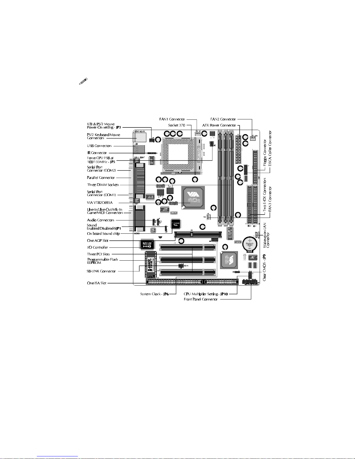
Shuttle® SpacewalkerTM HOT-687V
PPGA Celeron/Copprtminr processor based AGPset Mainboard
Manual Version 2.0
Copyright
Copyright© 2000 by Shuttle® Inc. All Rights Reserved.
No part of this publication may be reproduced, transcribed, stored in a retrieval system,
translated into any language, or transmitted in any form or by any means, electronic, mechanical, magnetic, optical, chemical, photocopying, manual, or otherwise, without prior
written permission from Shuttle® Inc.
Disclaimer
Shuttle® Inc. shall not be liable for any incidental or consequential damages resulting from
the performance or use of this product.
This company makes no representations or warranties regarding the contents of this
manual. Information in this manual has been carefully checked for reliability; however, no
guarantee is given as to the correctness of the contents. In the interest of continued product
improvement, this company reserves the right to revise the manual or include changes in the
specifications of the product described within it at any time without notice and without obligation to notify any persion of such revision or changes. The information contained in this
manual is provided for general use by the customers.
Trademarks
Spacewalker is a registerred trademark of Shuttle Inc.
Intel, Pentium is a registered trademarks of Intel Corporation.
PS/2 is a registered trademark of IBM Corporation.
AWARD is a registered trademark of Award Software Inc.
Microsoft and Windows are registered trademarks of Microsoft Corporation.
General Notice: Other brand and product names used herein are for identification purposes
only and may be trademarks of their respective owners.
M314
Page 3

- 2 -
Federal Communicationsr Commission (FCC)
Compliance Notice
This equipment has been tested and found to comply with the limits for a Class B digital
device, pursuant to Part 15 of FCC Rules. These limits are designed to provide reasonable
protection against harmful interference in a residential installation.
This equipment generates, uses and can radiate radio frequency energy. If not installed and
used properly, in strict accordance with the manufacturer's instructions, may cause harmful
interference to radio communications. However, there is no guarantee that interference will
not occur in a particular installation. If this equipment does cause interference to radio or
television reception, which can be determined by turning the equipment off and on, the user
is encouraged to try to correct the interference by one or more of the following measures :
Reorient or relocate the receiving antenna.
Increase the separation between the equipment and receiver.
Connect the equipment into an outlet on a circuit different from that to which the receiver is
connected.
Consult the dealer or an experienced radio/television technician for help and for additional
suggestions.
The user may find the following booklet prepared by the Federal Communications Commission helpful "How to Identify and Resolve Radio-TV Interference Problems." This booklet is
available from the U.S. Government Printing Office. Washington, DC 20402, Stock 004-00000345-4
CE Notice
This device complies with the requirements oof the EEC directive 89/336/EEC with regard to
EMC (Electromagnetic Compatibility). Following standards are applied to this product, in
order to achieve compliance with the EMC:
Immunity is in accordance with EN 50082-1 (1992).
Emissions are in accordance with EN 55022 (1987) Class B.
Page 4

- 3 -
TABLE OF CONTENTS
T
T
CHAPTER 1 INTRODUCTION ...........................................................................................4
CHAPTER 2 FEATURES .................................................................................................5
Specification .................................................................................................................................5
Accessories of HOT-687V..........................................................................................................7
CHAPTER 3 HARDWARE INSTALLATION ...........................................................................8
Install The CPU ...........................................................................................................................8
The PPGA Celeron Processor..................................................................................................8
Jumpers.........................................................................................................................................9
CPU Clock Speed and ratio Selection - JP6 and JP10...........................................................9
Force CPU FSB at 100/133MHz - JP5..................................................................................10
On Board Audio Controller Setting - SJP1 ...........................................................................11
Clear CMOS - JP9..................................................................................................................11
Keyboard & PS/2 Mouse Power-on Setting - JP3 ................................................................11
Connectors..................................................................................................................................12
Front Panel Connectors (JP11) ..............................................................................................12
(SPEAKER / IDE LED / PW ON / RST / PW LED / EPMI / GREEN LED)
Back Panel Connectors ..........................................................................................................13
(COM1 / COM2 / PS/2 Keyboard & PS/2 Mouse / Parallel Port / USB1 / USB2 /
Line-Out / Line-In / Mic/In / GAME/MIDI)
Other Connectors....................................................................................................................14
(ATX Power Supply / IR / Audio /FAN / EISCA / Wake-On-LAN / IDE &
Floppy / SB-LINK)
CHAPTER 4 MEMORY CONFIGURATION .........................................................................17
CHAPTER 5 FLASH UTILITY ........................................................................................18
CHAPTER 6 SOFTWARE ..............................................................................................20
CHAPTER 7 BIOS SETUP ..........................................................................................24
The Main Menu .........................................................................................................................25
Standard CMOS Setup .............................................................................................................27
BIOS Features Setup.................................................................................................................29
Chipset Features Setup .............................................................................................................32
Power Management Setup........................................................................................................35
PnP/PCI Configuration Setup..................................................................................................38
Load BIOS/SETUP Defaults ....................................................................................................40
Integrated Peripherals ..............................................................................................................41
Password Setting........................................................................................................................45
Save & Exit/Exit Without Saving............................................................................................46
Page 5

- 4 -
1
1
INTRODUCTION
Congratulations on your purchase of the HOT-687V computer mainboard.
HOT-687V is a highly integrated IBM PC/ATX compatible system board designed to meet the industry's
most demanding desktop applications.
Based on the VIA VT82C693A AGPset chipset which support up to 600+MHz PPGA Celeron
processor with MMX technology and Coppermine FC-PGA 667+MHz.
HOT-687V is equipped with an Accelerated Graphics Port (A.G.P.), a high-performance interconnect
for graphic-intensive application, such as 3D applications. The A.G.P. is independent of the PCI bus
and is designed to exclusively use with graphical-display devices. The HOT-687V supports 3.3 V
A.G.P. devices with data transfer rates up to 133 MHz, allowing data throughput of 500 MB/sec.
The VIA VT82C693A AGPset chipset provides an integrated Bus Mastering IDE controller with two
high performance IDE interfaces which allows up to four IDE devices connection and up to 66 MB/
sec of data transfer rates.
Onboard FM801 is an advanced PCI audio controller, it is compatible with Microsoft Windows,
DirectX and Adlib Music Synthesizer, Sound Blaster Pro and supports thousands of DOS games.
The on-board I/O controller provides standard PC I/O functions:
floppy drive interface, two FIFO serial ports, an IrDA device port and a SPP/EPP/ECP capable
parallel port.
HOT-687V is built with three PCI local bus slots providing a high bandwidth data path for data-
movement intensive functions such as graphics, and with one ISA slot.
HOT-687V provides the foundation for cost effective, high performance and highly expandable
platforms, which delivers the latest in the Intel FC-PGA Coppermine processor and new advanced
chipset technology.
Page 6

- 5 -
2
2
FEATURES
Specification
The HOT-687V Mainboard is carefully designed for the demanding PC user who wants high
performance and many intelligent features in a compact package:
Chipset:
Features VIA VT82C693A AGPset with I/O subsystems.
CPU Support:
Intel PPGA Celeron processor 300~600+ MHz.
Intel Coppermine FC-PGA 500~667+ MHz.
Versatile Memory Supports:
Supports three banks of normal or PC66/PC100/PC133 SDRAM maximum memory size
up to 768MB.
Configurable support for ECC (Error Checking and Correcting)
PCI and ISA Expansion Slots:
Provides three 32-bit PCI slots, one 16-bit ISA slot and one AGP slot.
AGP (Accelerated Graphics Port):
AGP Specification 1.0
HOT-687V main board equipped with an AGP slot for an AGP VGA card that supports
133MHz 2X mode for texture mapping z-buffering and alpha blending. AGP allows 3D
applications to run faster and smoothly.
Onboard I/O:
One Floppy port;
One PS/2 mouse and PS/2 Keyboard port connector
Two high-speed UART compatible serial ports
Serial Port 2 can also be directed from COM2 to the Infrared Module for wireless connections.
One parallel port with ECP and EPP capabilities.
Onboard Audio Controller:
Proprietary logic for Real DOS games support
Hardware Synthesizer for AdLib and General MIDI compatibility
Optional QSound HSP dynamic 3-D positional audio suport
S/PDIF digital output port
Built-in SRC (sampling rate converter)
Page 7

- 6 -
Onboard PCI Bus Master IDE Controller:
Two Ultra DMA33/66 Bus Master IDE Ports supports four IDE devices up to 66 MB/sec
IDE transfers and supports Enhanced PIO Modes 3 and 4 and Bus Master IDE DMA Mode 2
devices.
Onboard 20-pin ATX Power Supply:
ATX power supply unit can connect to the 20-pin ATX power connector onboard, supporting
Suspend and soft-on/off by dual-function power button.
System BIOS:
Provides licensed Award V4.51PG BIOS on Flash EEPROM.
Supports Green PC, DMI and Bundled with NCR SCSI BIOS.
ACPI:
Support ACPI (Advanced Configuration and Power Interface) function. ACPI provide
more Energy Saving Features for the future operating system supporting OS Direct Power
Management (OSPM) functionality.
Board Size:
Micro-ATX form factor 244mm x 190mm.
Advanced Features:
Low EMI -- Spread Spectrum built in - ±0.5% or ±0.3% modulation and automatic clock
shut-off of unused PCI/SDRAMS slots to reduce the EMI.
Dual Function Power Button -- The system can be one of two states, one is Suspend mode
and the other is the Soft-off mode. Pushing the power button for less than 4 seconds will
place the system into Suspend mode. When push the power button for more than 4 seconds,
the system enters the Soft-off mode.
Wake-On-LAN -- The system will power-on automatically by activating of LAN.
(This function support Intel LAN card only).
Modem Ring Power-on -- The system will power-on automatically by activating of modem
ring.
PS/2 Keyboard & Mouse Power-on -- The system will power-on automatically by stroke
keyboard or double click PS/2 mouse.
Optional Features:
Voltages Monitoring -- System voltages levels are monitored to ensure stable current to
main board components.
System voltages include VCORE and VTT for CPU, and +5V, +12V, -5V, -12V for system.
FAN Status Monitoring -- To prevent CPU overheat, CPU fans is monitored for RPM and
failure. (CPU Cooling FAN with RPM sensor is required)
Page 8
- 7 -
Accessories of HOT-687V
Page 9
- 8 -
Figure 3-2
3
3
HARDWARE INSTALLATION
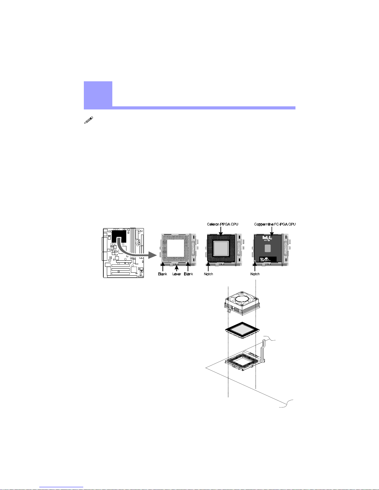
Then you should have a CPU fan that
will cover the face of the CPU. Apply
thermal jelly to the CPU metallic top and
then install the fan onto the CPU. (Figure
3-2 )
Install The CPU
The Installation PPGA Celeron Processor
HOT-687V mainboard provides a 370-pin ZIF Socket370 for Intel PPGA Celeron and FCPGA Coppermine CPU. The CPU that came with the mainboard should have a fan attached
to it to prevent overheating. If this is not the case then purchase a fan before you turn on
your system.
To install a CPU, first turn off your system and remove its cover. Locate the ZIF Socket370
and open it by first pulling the lever sideways away from the socket then upwards to a 90degree right angle. Insert the CPU with the correct orientation as shown.(Figure 3-1) Use
the notched corner of the CPU as your guide. The notched corner should point towards the
end of the lever. Notice that there are two blank area where one hole is missing from that
corner of the square array of pin holes. Because the CPU has a corner pin for two of the four
corner, the CPU will only fit in the one orientationn, hold down on the CPU and close the
socket’s lever.
Figure 3-1
Page 10
- 9 -
Jumpers
Several hardware settings are made through the use of jumper caps to connect jumper pins
on the main board. The jumper's pin 1 on main board will be on the top or on the left when
holding the main board with the keyboard connector away from yourself.
Jumpers with two pins will be shown as for Close (On) and for Open (Off).
To connect the pins, simply place a plastic jumper cap over the two pins.
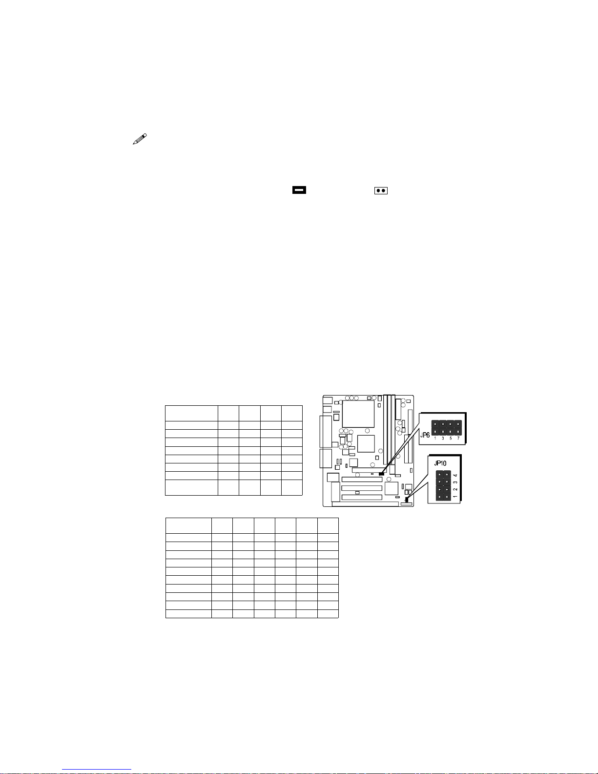
CPU Host Frequency Setting - JP6 and JP10
The CPU host frequency is set to Auto-detecting by BIOS. It is defined according to Intel
Celeron CPU specification. We strongly advise novice users not to modify the original
setting, for setting an incorrect value may damage your CPU.
For experienced users, the HOT-687V mainboard provides an alternative Hard-Configure
function to adjust your CPU host frequency manually.
Note: Before you adjust your CPU host frequency by jumper, you need to
set CPU Host Clock (CPU/PCI) to Disabled in Chipset Features Setup of
BIOS setup program.
Insert mini-jumper caps properly on JP6 and JP10 to reach desired CPU
Host Frequency, as shown in the following table.
System Clo ck
(JP6)
1-2 3-4 5-6 7-8
66 MHz OFF OFF ON ON
75 MHz OFF ON ON ON
83 MHz ON OFF ON ON
100 MHz OFF OFF OFF ON
103 MHz ON ON OFF ON
112 MHz OFF ON OFF O N
124 MHz ON OFF OFF OFF
133 MHz /
(BIOS Setup)
OFF OFF OFF OFF
Figure 3-3
Multiplier
(JP10)
1-6 2-7 3-8 4-9
(66)
MHz
(100)
MHz
3.5X ON OFF ON OFF 350
4X OFF ON ON ON 400
4.5X OFF ON ON OFF 300 450
5X OFF OFF ON ON 333 500
5.5X OFF OFF ON OFF 366 550
6X ON ON OFF ON 400 600
6.5X ON ON OFF OFF 433 650
7X ON OFF OFF O N 466 700
7.5X ON OFF OFF OFF 500
8X OFF ON OFF ON
Table 3-1
Table 3-2
Note: Normally, Celeron and Coppermine processor's ratio are not adjustable.
Page 11
- 10 -
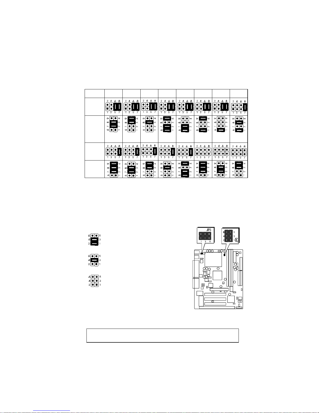
CPU Host Clock and Clock Ratios Configuration Table (Table 3-3) shows the PPGA Celeron
processor 300 MHz ~ 600+ MHz and Coppermine FC-PGA 500~667+ MHz quick setting on
the mainboard.
Process or
300 MHz
(66MHz x 4.5)
333 MHz
(66MHz x 5)
366 MHz
(66MHz x 5.5)
400 MHz
(66MHz x 6)
433 MHz
(66MHz x 6.5)
466 MHz
(66MHz x7)
500 MHz
(66MHz x 7.5)
350 MHz
(100MHz x 3.5)
System Clock
JP6
Multiplier
JP10
Process or
400 MHz
(100MHz x 4)
450 MHz
(100MHz x 4.5)
500 MHz
(100MHz x 5)
550 MHz
(100MHz x 5.5)
600 MHz
(100MHz x 6)
533 MHz
(133MHz x 4)
600 MHz
(133MHz x 4.5)
667 MHz
(133MHz x 5)
System Clock
JP6
Multiplier
JP10
Table 3-3
Set CPU host clock Auto-detecting
and setting by system BIOS (Default)
Set CPU host clock hard-configure
to 100MHz.
Set CPU host clock hard-configure
to 133MHz.
However, HOT-687V provide over clocking feature to processor host clock, it is not a
recommended practice, for this may cause severe damage to the system.
Warning: Over-clocking is not a recommended practice for it may damage both the
mainboard and the processor.
Figure 3-4
HOT-687V mainboard provide jumper JP5 to set CPU host clock auto-detect by system
BIOS or hardware configure the CPU host clock to 66MHz, 100MHz or 133MHz manually
for over-clocking your 66MHz-based processor up to 100MHZ, or over-clocking your
100MHz-based porcessor up to 133MHz.
Force CPU FSB at 100/133MHz - JP5
Page 12
- 11 -
Keyboard & PS/2 Mouse Power-On Setting - JP3
HOT-687V mainboard provides an optional power-on function by stroke any key (or hotkey) on keyboard or double click on PS/2 mouse.
Note: Power-on by serial mouse is not supported
JP3 is the jumper used to set the functions of keyboard & PS/2 mouse power-on Enabled
or Disabled.
When you enabled K/B & PS/2 Mouse Power-ON function, you also have to set the
proper item on POWER ON function category of Integrated Peripherals of BIOS
setup.
K/B & PS/ 2 Mous e Powe r-On JP3
Keyboard &
PS/2 Mouse
Power-On
Disabled
Keyboard &
PS/2 Mouse
Power-On
Enabled
PS/2 Mouse
Power-On
Enabled
Table 3-4
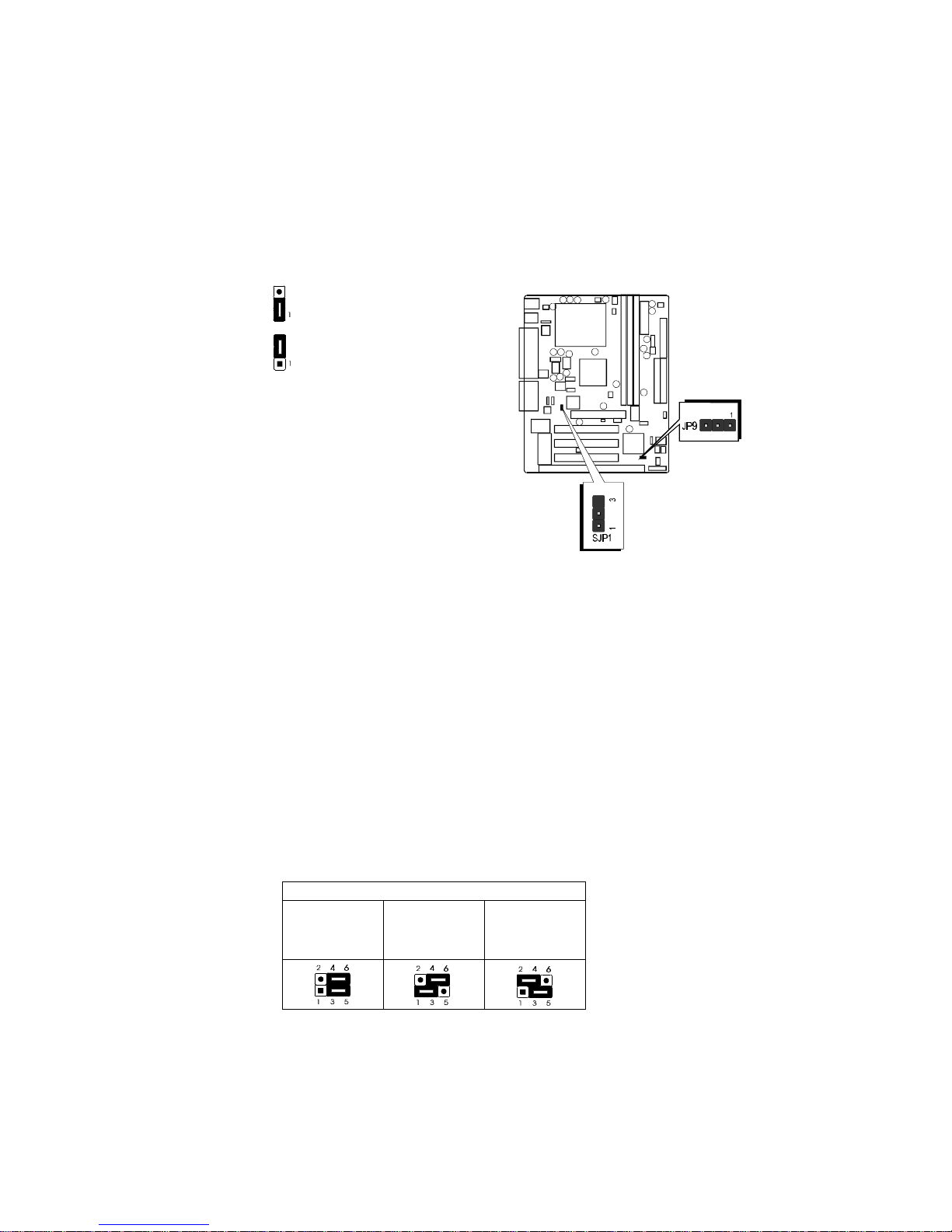
On Board Audio Controller Setting - SJP1
HOT-687V mainboard provides on-board QSound HSP dynamic 3-D positional audio
controller chip. Jumper SJP1 is used to enabled or disabled it.
On-board Audio Controller Enabled
On-board Audio Controller Disabled
Clear CMOS - JP9
HOT-687V mainboard supports jumper JP9 for
discharging mainboard's CMOS memory.
This jumper can clear the CMOS data stored in
the Giga I/O chip. To clear the CMOS data please
follow listed steps:
1) Turn off the PC,
2) Remove mini jumper from JP9 pin 1-2,
3) Insert mini jumper to JP9 pin 2-3 for a brief while,
4) Remove mini jumper from JP9 in 2-3,
5) Reinsert mini jumper to JP9 pin 1-2,
6) Turn on the PC.
Figure 3-5
Page 13
- 12 -
Connectors
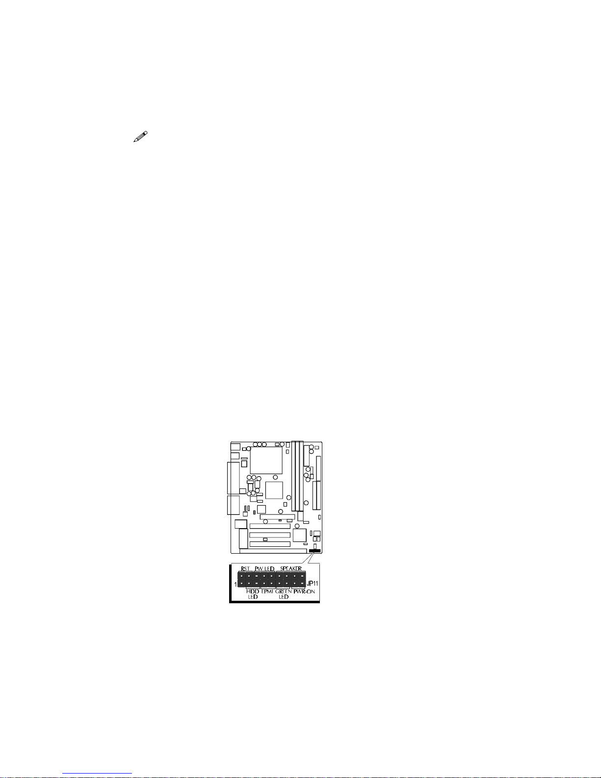
Front Panel Connectors (JP11)
Speaker Connector - SPEAKER
PC speaker connector may attach a 4-pin PC speaker cable from the case to this connector.
HDD LED Connector - IDE LED
Attach a 2-pin IDE drive LED cable to this connector. The LED lights when an IDE device is
active.
ATX Power On/Off Switch Connector - PW ON
Attach a 2-pin momentary type switch to this connector for turning on or off your ATX power
supply.
Hardware Reset Connector - RST
Attach 2-pin hardware reset switch to it. Closing the reset switch restarts the system.
PW-LED Connector - PW LED
Power LED connector is a 3-pin connector for attached to the case's Power LED.
EPMI Connector - EPMI
Hardware System Management Interface connector may attach a 2-pin momentary switch to
it. When push it will force system get into power saving mode, and the system will resume
when switch is pushed again.
GLED Connector - GREEN LED
Attach a 2-pin Green LED cable to it. The Green LED lights when the system get intopower
saving mode.
Figure 3-6
Page 14
- 13 -
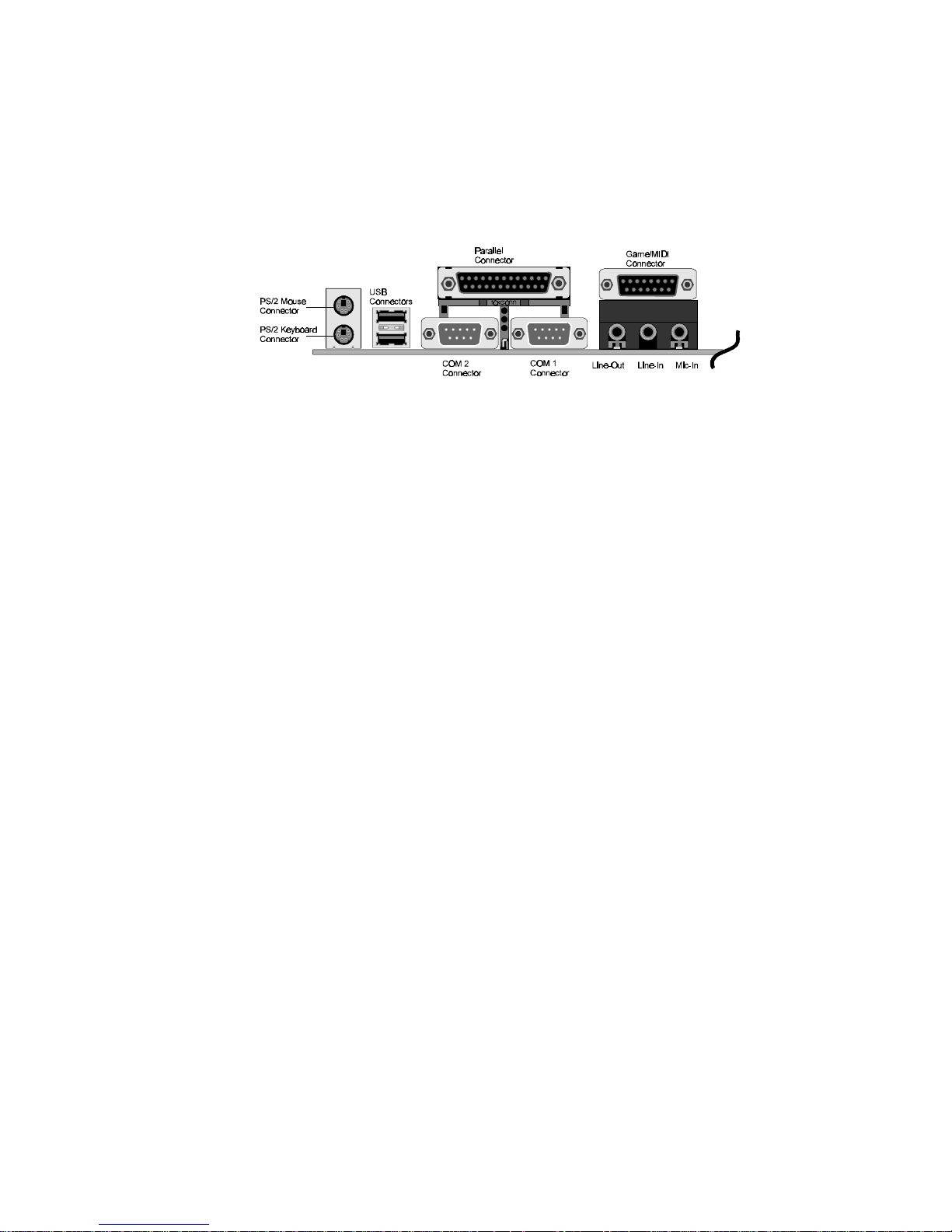
Back Panel Connectors
COM1/COM2 Connectors
This mainboard can accommodate up to two serial devices on COM1 and COM2.
Attach each serial device cable to the DB9 serial port COM1/COM2 at the back panel of
your computer.
PS/2 Keyboard & PS/2 Mouse Connector
Two 6-pin female PS/2 keyboard & Mouse connectors are located at the rear panel of
the main board. Depending on the computer housing you use (desktop or minitower),
the PS/2 Mouse connector is situated at the top of the PS/2 Keyboard connectoor when
the mainboard is laid into a desktop, as opposed to a mini-tower where the PS/2 Mouse
connector is located at the right of the PS/2 Keyboard's. Plug the PS/2 keyboard and
mouse jacks into their corresponding connectors.
Parallel Port Connector
One DB25 female parallel connector is located at the rear panel of the mainboard. Plug
the connection cable from your parallel device (printer, scanner, etc.) into this connector.
USB1/USB2 Port Connectors
Two female connectors USB1/USB2 share the same USB (Universal Serial Bus) bracket
at the rear panel of your mainboard. Plug each USB device jack into an available USB1/
USB2 connector.
Line-Out
Line-Out is a stereo output through which the combined signal of all internal and
external audio sources on the board is output. It can be connected to 1/8-inch TRS stereo
headphones or to amplified speakers.
Line-In
Line-In is a stereo line-level input that accepts a 1/8-inch TRS stereo plug. It can be used
as a source for digital sound recording, a source to be mixed with the output, or both.
Figure 3-7
Page 15
- 14 -
Mic-In
MIC-IN is a 1/8-inch jack that provides a mono input. It can use a dynamic mono or stereo
microphone with a resistance of not more than 600 ohms.
GAME/MIDI
The GAME/MIDI port is a 15-pin female connector. This port can be connected to any IBM
PC compatible game with a 15-pin D-sub connector.
MIDI Instrument Connection
You need a MIDI adapter to connect a MIDI instrument to the sound card. The MIDI adapter
can be connected to the Joystick/MIDE port. You will also need MIDI sequencing software to
run MIDI instruments with your computer.
Figure 3-10
Other Connectors
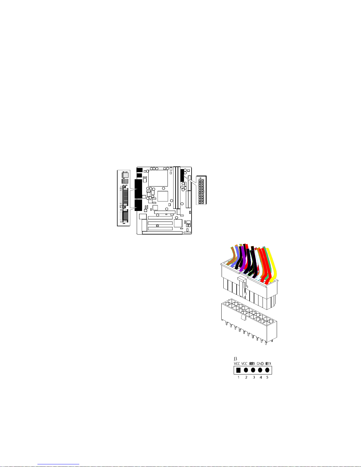
ATX Power Supply Connector - J4
It is a 20-pin male header connector is connected to the ATX
power supply. The plug of the power supply will only insert
in one orientation because of the different hole shade and
size. Find the proper orientation and push down firmly
making sure that the pins are aligned.
IR Connector - J3
If you have an Infrared device, this mainboard can implement
IR (Infrared) transfer and meet both ASKIR and HPSIR specifications. To enable the IR transfer function, follow these steps:
Step 1. Attach the 5-pin infrared device cable to J3
connector. (Refer to the above diagram for IR pin
assignment.)
Step 2. Configure the Infrared transfer mode in the
UR2 Mode field of Integrated Peripherals menu
in BIOS Setup. This mainboard supports IrDA
1.0, ASKIR, MIR 0.57M and MIR 1.15M trans
fer modes. FIR is not currently supported.
Figure 3-9
Figure 3-8
Page 16

- 15 -
Audio Connectors SJ1/SJ2
MODEM/TAD IN/OUT
Port SJ1 can be used to connect a modem audio line to HOT-687V. You would use this
connector when using telephone answering machine software for input and output.
TAD
SJ1:
1=PHONE 2=Ground 3=Ground 4=MONO
CD AUDIO INPUT
Port SJ2 is used to attach a CD-ROM audio connector.
CD_IN
SJ2:
1=Left Channel 2=Ground 3=Ground 4=Right Channel
CPU, Chassis & AGP cooling Fan connectors - FAN1, FAN2, FAN3
The main board provides three onboard 12V cooling
fan power connectors. Depending on the fan maker,
the wiring and plug may be different. The red wire should be connected to +12V and black
wire should be connected to ground (GND).
EISCA Coller Connector - J5
Pin Assignments:
1=SMBCLK 2=SMBDATA 3=THRM 4=Empty 5=Vcc 6=SPK1
7=GND 8=Vcore 9=FAN2 10=Vcc3 11=FAN1 12= Vcc
Figure 3-11
Page 17

- 16 -
Wake-On-LAN Connector - J11
Attach a 3-pin connector from the LAN card which supports the Wake-On-LAN (WOL)
function. This function lets users wake up the connected system
through the LAN card.
Enhanced IDE and Floppy connectors
The mainboard features two 40-pin dual-channel IDE device connectors (IDE1/IDE2)
providing support for up to four IDE devices, such as CD-ROM and Hard Disk Drivers
(H.D.D.). This mainboard also includes one 34-pin floppy disk controller (FDC) to accommodate the Floppy Disk Drive (F.D.D.).
This mainboard comes with one 40-pin ribbon cable to connect to IDE H.D.D and one 34-pin
ribbon cable for F.D.D.
Ribbon cables are directional, therefore, make sure to always
connect with the red cable-strip on the same side as pin #1 of
the IDE1/IDE2 or FDC connector on the mainboard.
SB-Link connector - JP7
The main board provides a 2x3 pin SB-Link header accepts the Creative CT4600 series PCI
sound cards with PCI solution to connect the legacy Sound Blaster compatible audio to the
PCI bus.
Figure 3-12
Pin Assignments:
1=GNT#A 2=GND 3=Empty 4=REQ#A 5=GND 6=SERIRQ
Page 18

- 17 -
MEMORY CONFIGURATION
4
4
The HOT-687V mainboard provides three 168-pin DIMM sockets that make it possible to
install from 16MB up to 768MB of SDRAM. The DIMM socket support 16MB, 32MB,
64MB, 128MB and 256MB 3.3V single- or double- side SDRAM DIMM.
The three DIMM sockets are arranged in three banks of one socket each, Each bank provides a 64/72-bit wide data path.
HOT-687V provides optional data integrity features including EC (Error Checking) or ECC
(Error Checking and Correcting) in the memory array. EC mode provides single and
multiple bit error detection. In ECC mode, during reads from the DRAM, the HOT-687V
provides error checking and correction of the data.
To support ECC, you must use true (opposed to phantom parity generated by TTL chips) 72bit parity-type DIMM for all modules.
Install Memory
Install memory in any or all of the banks and in any combination, as follows:
DIMM
Socket
Memory Modules
Moudule
Quantity
DIMM 1
16MB, 32MB, 64MB, 128MB, 256MB 168-pin
3.3V SDRAM DIMM
x 1
DIMM 2
16MB, 32MB, 64MB, 128MB, 256MB 168-pin
3.3V SDRAM DIMM
x 1
DIMM 3
16MB, 32MB, 64MB, 128MB, 256MB 168-pin
3.3V SDRAM DIMM
x 1
Table 4-1
Upgrade Memory
You can easily upgrade the system memory by inserting additional SDRAM modules in
available DIMM banks. The total system memory is calculated by simply adding up the
memory in all DIMM banks. After upgrade, the new system memory value will automatically be computed and displayed by the BIOS Standard CMOS Setup menu.
Page 19

- 18 -
5
5
FLASH UTILITY
This chapter briefly discusses Award Flash utility in order to guide you through updating
your old BIOS. The file name we use to program here is test.bin, and the file name to save
old BIOS is 687V.OLD. Please note that those file names are not absolute. They are only
examples to let you have a more clear understanding of the updating process.
How to Begin
1. Please type “awdflash” and press the ENTER key to begin the updating process.
2. Once you enter, you will see a main menu displaying:
3. Move the cursor to “File Name to Program: “
4. Type the program name “test.bin”, and then press the ENTER key.
5. At the bottom of the menu, you will be requested to answer:
“Do You Want to Save BIOS (Y/N)? “
The following manual is intended to guide you through the process of both “No” and “Yes”
cases respectively.
If “No”
If you do not wish to save the old BIOS:
1. Please type “N”, and then press the ENTER key.
2. Then you will be requested to answer:
“Are You Sure to Program? “
3. Answer “N” if you do not want to program, and then it will exit.
Page 20

- 19 -
If “Yes”
To save the old BIOS:
1. Please respond “Y”, and then press the ENTER key.
2. Move the cursor to “File Name to Save: “
3. Type file name “TEST.BIN”, and then press the ENTER key. (Your old BIOS will be
saved in the file name you create. In this case, the old BIOS is saved in the file
name, 687V.OLD).
4. Then you will be requested to answer:
“Are You Sure to Program (Y/N)? “
5. Type “Y” to begin programming, and press the ENTER key.
6. When the programming is finished, the showing message will appear:
7. Once you see the showing message “Power Off or Reset System”, please restart your
system.
8. When you power on the computer again, you will find your old BIOS has already
been successfully updated.
To view a complete usage of FLASH utility, please type “awdflash /?” and press the ENTER key.
Notes About Award Flash Utility
Please note that Award Flash Utility cannot run under EMM386 or QEMM. Thus, when
executing the command “awdflash”, an error message will appear:
“Error Message: Fail — Due to EMM386 or QEMM !”
Page 21

- 20 -
SOFTWARE SETUP
6
6
6.1 HOT-687V Mainboard CD Overview
Note: The HOT-687V mainboard attachment CD contents are subject to change without
notice.
To start your mainboard CD disc, just insert it into your CD-ROM drive and the CD
AutoRun screen should appear. If the AutoRun screen does not appear, double click or run
D:\Autorun.exe (assuming that your CD-ROM drive is drive D:)
Navigation Bar Description:
Install Mainboard Software - Installing HOT-687V Mainboard Drivers for
Windows.
Install Audio Driver Software - Installing Audio software Drivers.
Manual - HOT-687V series mainboard user's manual in PDF format.
Link to Shuttle Homepage - Link to shuttle website homepage.
Browse this CD - Allows you to see the contents of this CD.
Quit - Close this CD.
Page 22

- 21 -
6.2 Install Mainboard Driver
Insert the attachment CD into your CD-ROM drive and the CD AutoRun screen should
appear. If the AutoRun screen does not appear, double click on Autorun icon in My
Computer to bring up Shuttle Mainboard Software Setup screen.
Select using your pointing device (e.g. mouse) on the “Install Mainboard Software” bar.
Once you made your selection, a Setup window which automatically runs the installation.
When the files are done copying make sure you reboot the system to insure that the files are
installed correctly.
Page 23

- 22 -
6.3 Install Audio Driver
Insert the attachment CD into your CD-ROM drive and the CD AutoRun screen should
appear. If the AutoRun screen does not appear, double click on Autorun icon in My
Computer to bring up Shuttle Mainboard Software Setup screen.
Select using your pointing device (e.g. mouse) on the “Install Audio Device Software” bar.
Once you made your selection, a Setup window which automatically runs the installation.
When the files are done copying make sure you reboot the system to insure that the files are
installed correctly.
Then ForteMedia PCI Audio Drivers & Applications windows will appear on your screen.
Click on the “Install FM801 Driver” bar.
Page 24

- 23 -
6.4 To View the User's Manual
Insert the attachment CD into your CD-ROM drive and the CD AutoRun screen should
appear. If the AutoRun screen does not appear, double click on Autorun icon in My
Computer to bring up Shuttle Mainboard Software Setup screen.
Select using your pointing device (e.g. mouse) on the “Manual” bar.
Then click on "HOT-687V Manual" bar to view HOT-687V user's manual.
Then Online Information windows will appear on your screen. Click on the “Install
Acrobe Reader 3.0” bar if you need to install acrobe reader.
Page 25

- 24 -
BIOS SETUP
7
7
The BIOS ROM has a built-in Setup program that allows users to modify the basic system
configuration. This type of information is stored in battery-backed RAM so that it retains
the Setup information when the power is turned off.
Entering Setup
Power on the computer and press <Del> immediately will allow you to enter Setup. The
other way to enter Setup is to power on the computer, when the below message appear
briefly at the bottom of the screen during the POST (Power On Self Test), press <Del> key
or simultaneously press <Ctrl>,<Alt>, and <Esc> keys.
“Press DEL to enter SETUP”
If the message disappears before you respond and you still wish to enter Setup, restart the
system to try again by turning it OFF the ON or pressing the “RESET” button on the system
case. You may also restart by simultaneously press <Ctrl>,<Alt>, and <Delete> keys. If
you do not press the keys at the correct time and the system does not boot, an error message
will be displayed and you will again be asked to,
“Press F1 to Continue, DEL To Enter Setup”
Page 26

- 25 -
The Main Menu
Standard CMOS setup
This setup page includes all items in a standard compatible BIOS.
BIOS features setup
This setup page includes all items of Award special enhanced features.
Chipset features setup
This setup page includes all items of chipset features.
Power Management Setup
This setup page includes all items of Power Management features.
PnP/PCI Configuration setup
This item specifies the value (in units of PCI bus blocks) of the latency timer for the
PCI bus master and the IRQ level for PCI device. Power-on with BIOS defaults
Load BIOS Defaults
BIOS defaults loads the values required by the System for the maximum performance.
However, you can change the parameter through each Setup Menu.
Load Setup Defaults
Setup defaults loads the values required by the system for the O.K. performance.
However, you can change the parameter through each Setup Menu.
Integrated Peripherals
This setup page includes all items of peripheral features.
Page 27

- 26 -
Supervisor Password
Change, set, or disable supervisor password. It allows you to limit access to the system
and Setup, or just to Setup.
User Password
Change, set, or disable user password. It allows you to limit access to the system and
Setup, or just to Setup.
IDE HDD auto detection
Automatically configure IDE hard disk drive parameters.
Save & Exit setup
Save CMOS value change to CMOS and exit setup
Exit without saving
Abandon all CMOS value changes and exit setup.
Page 28

- 27 -
Standard CMOS Setup
Date
The date format is <day>, <month> <date> <year>. Press <F3> to show the calendar.
Time
The time format is <hour> <minute> <second>. The time is calculated base on the
24-hour military-time clock. For example. 5 p.m. is 17:00:00.
Hard Disks Type
This item identify the types of hard disk drives that has been installed in the computer.
There are 46 predefined types and a user definable type.
Press PgUp or PgDn to select a numbered hard disk type or type the number and press
<Enter>. Note that the specifications of your drive must match with the drive table.
The hard disk will not work properly if you enter improper information for this item.
If your hard disk drive type is not matched or listed, you can use Type User to define
your own drive type manually.
If you select Type User, related information is asked to be entered to the following
items. Enter the information directly from the keyboard and press <Enter>. Those
information should be provided in the documentation from your hard disk vendor or
the system manufacturer.
The user may also set those items to AUTO to auto configure hard disk drives parameter when system power-on.
If a hard disk drive has not been installed select NONE and press <Enter>.
Drive A type/Drive B type
This item specifies the types of floppy disk drive A or drive B that has been installed
in the system.
Page 29

- 28 -
Video
This item selects the type of adapter used for the primary system monitor that must
matches your video display card and monitor. Although secondary monitors are supported, you do not have to select the type in Setup.
Error halt
This item determines if the system will stop, when an error is detected during power up.
Memory
This item is display-only. It is automatically detected by POST (Power On Self Test) of
the BIOS.
Base Memory
The POST of the BIOS will determine the amount of base (or conventional) memory
installed in the system. The value of the base memory is typically 512K for systems
with 512K memory installed on the mainboard, or 640K for systems with 640K or more
memory installed on the mainboard.
Extended Memory
The BIOS determines how much extended memory is present during the POST. This is
the amount of memory located above 1MB in the CPU's memory address map.
Page 30

- 29 -
Virus Warning
When this item is enabled, the Award BIOS will monitor the boot sector and partition
table of the hard disk drive for any attempt at modification. If an attempt it made, the
BIOS will halt the system and the following error message will appear. Afterwards, if
necessary, you will be able to run an anti-virus program to locate and remove the
problem before any damage is done.
CPU Internal Cache
This item enables CPU internal cache to speed up memory access.
External Cache
This item enables CPU secondary cache to speed up memory access.
CPU L2 Cache ECC Checking
When you select Enabled, memory checking is enable when the external cache
contains ECC SRAMs.
Processor Number Feature
This item Enabled/Disabled the Pentium III processor serial number only Pentium III
with processor serial number feature will show this item.
!WARNING!
Disk boot sector is to be modified
Type "Y" to accept write or "N" to abort write
Award Software, Inc.
BIOS Features Setup
Page 31

- 30 -
Quick Power On Self Test
This item speeds up Power On Self Test (POST) after you power on the computer. If it is
set to Enabled, BIOS will shorten or skip some check items during POST.
Boot Sequence
This item determines which drive computer searches first for the disk operating system.
Default setting is A, C, SCSI.
BIOS also support system boot from CD-ROM drive or SCSI hard disk drive.
Swap Floppy Drive
When this item enables, the BIOS will swap floppy drive assignments so that Drive A:
will function as Drive B: and Drive B: as Drive A:.
Boot Up Floppy Seek
When this item enables, the BIOS will swap floppy drive assignments so that Drive A:
will function as Drive B: and Drive B: as Drive A:.
Boot Up NumLock Status
When this option enables, BIOS turns on Num Lock when system is powered on.
IDE HDD Block Mode
This item is used to set IDE HDD Block Mode. If your IDE Hard Disk supports block
mode, then you can enable this functiuon to speed up the HDD access time. If not, please
disable this function to avoid HDD access error.
Gate A20 Option
This entry allows you to select how the gate A20 is handled. The gate A20 is a device
used to address memory above 1 MByte. Initially, the gate A20 was handled via a pin on
the keyboard. Today, while keyboards still provide this support, it is more common, and
much faster, set to Fast for the system chipset to provide support for gate A20.
Memory Parity/ECC Check
This item allowa you to set memory error checking, Enabled or Disabled.
Typematic Rate Setting
This determines if the typematic rate is to be used. when disabled, continually holding
down a key on your keyboard will generate only one instance. In other words, the BIOS
will only report that the key is down. When the typematic rate is enabled, the BIOS will
report as before, but it will then wait a moment, and, if the key is still down, it will begin
the report that the key has been depressed repeatedly. For example, you would use such a
feature to accelerate cursor movements with the arrow keys.
Typematic Rate (Chars/Sec)
When the typematic rate is enabled, this selection allows you select the rate at which the
keys are accelerated.
Typematic Delay (Msec)
When the typematic rate is enabled, this selection allows you to select the delay between
when the key was first depressed and when the acceleration begins
Page 32

- 31 -
Security Option
This item allows you to limit access to the System and Setup, or just to Setup.
When System is selected, the System will not boot and access to Setup will be denied if the
correct password is not entered at the prompt.
When Setup is selected, the System will boot, but access to Setup will be denied if the
correct password is not entered at the prompt.
PCI/VGA Palette Snoop
This item must be set to enabled if there is a MPEG ISA card installed in the system, and
disabled if there is no MPEG ISA card installed in the system.
OS Select For DRAM > 64MB
This item allows you to access the memory that over 64 MB in OS/2.
Video BIOS Shadow
Determines whether video BIOS will be copied to RAM. However, it is optional depending
on chipset design. Video Shadow will increase the video speed.
C8000-CBFFF Shadow/DC000-DFFFF Shadow
These categories determine whether option ROMs will be copied to RAM. An example of
such option ROM would be support of SCSI Add-on card.
Page 33

- 32 -
Chipset Features Setup
Bank X/X DRAM Timing
This value in this field is set by the system board manufacturer, depending on whether the
board has paged DRAMS or EDO DRAMS. The choice: 70ns, 60ns.
SDRAM Cycle Length
This field allows you to set the SDRAM latency timer.
The Choice: 2,3.
DRAM Clock
This item set the DRAM Read/Write timings that the system uses.
Memory Hole
In order to improve performance, some space in memory can be reserved for ISA cards.
Read Around write
This is a new cache technology for the video memory of the processor. It can greatly
improve the display speed by caching the display data. You must leave this on the default
setting of Disabled if your display card cannot support this feature or else your system
may not boot.
Concurrent PCI/Host
This item disable CPU bus will be occupited during the entire PCI operation period.
System BIOS Cacheable
This item allows the user to set whether the system BIOS F000~FFFF areas are cacheable
or non-cacheable.
Page 34

- 33 -
Video RAM Cacheable
This is a new cache technology for the video memory of the processor. It can greatly
improve the display speed by caching the display data. You must leave this on the default
setting of Disabled if your display card cannot support this feature or else your system
may not boot.
AGP Aperture Size (MB)
This item allows the user to set memory-mapped, graphics data structures can reside in
Graphics Aperture.
AGP-2X Mode
This item allows you to enable/disable AGP-2X function. See www.apgforum.org for
AGP information.
OnChip USB
Select Enabled if your system contains a Universal Serial Bus (USB) controller and you
have a USB peripheral.
Wake Up On LAN
This item determine the system will resume by activity of LAN. If enabled this feature
system will power-on itself from power off when the activity of LAN.
Auto Detect DIMM/PCI Clock
Enabling this item allows system auto detect and close clock signal to empty DIMM/PCI
slot to reduce EMI.
Spread Spectrum
This item allows the user to enable Spread Spectrum Modulated to reduce the EMI.
CPU Host Clock (CPU/PCI)
This item allows the user may adjust CPU Host Clock from 66 MHz to 133 MHz.
CPU Warning Temperature (optional peature)
Since the mainboard support CPU temperature monitoring and overhear alert. This item
allows the user to set the threshold of CPU warning temperature. When CPU temperature
over the threshold, system will slow down clock to prevent CPU damage.
Current System Temp (optional peature)
Since the mainboard support System temperature monitoring and overheat alert.
This item indicate the current main board temperature.
Current CPU Temperature (optional peature)
Since the mainboard support CPU temperature monitoring and overheat alert.
This item indicate the current Processor temperature.
Current CPUFAN1/2/3 Speed (optional peature)
The mainboard can detect three fans rotation speed for CPU cooler and system.
Page 35

- 34 -
IN0(V) ~ IN2(V), +5V ~ -5V (optional peature)
The mainboard support CPU and mainboard voltages monitoring. The onboard hardware monitor
is able to detect the voltages output of the voltage regulators and power supply.
Shutdown Temperature (optional peature)
Select the combination of lower and upper limits for the system shutdown temperature, if your
computer contains an environmental monitoring system. If the temperature extends beyound either
limit, the system shuts down.
Page 36

- 35 -
Power Management Setup
ACPI function
This item determines whether to support ACPI function or not.
Power Management
This item determines the options of the power management function. Max Saving puts the
system into power saving mode after a brief period of system inactivity; Min Saving is
the same as Max Saving except the time of the system inactivity period is longer; Dis-
abled disables the power saving feature; User Defined allows you to set power saving
options according to your preference.
PM Control by APM
If this item set to No, system BIOS will be ignored and APM calls the power to manage
the system.
If this item setup to Yes, system BIOS will wait for APM's prompt before it enter any PM
mode e.g. DOZE, STANDBY or SUSPEND.
Video Off After
This item define when to activate the video off feature for monitor power management.
The settings are N/A, Doze, Standby and Suspend.
Video Off Method
This item define the video off features -V/H SYNC + Blank, DPMS, and Blank Only. The
first option, which is the default setting, blanks the screen and turns off vertical and
horizontal scanning; DPMS allows the BIOS to control the video display card if it supports the DPMS feature; Blank Screen only blanks the screen.
Page 37

- 36 -
MODEM Use IRQ
This item determines the IRQ in which the MODEM can use.
The choice: 1, 3, 4, 5, 7, 9, 10, 11, N/A.
Soft-Off by PWRBTN
The setting of Instant-Off allows the ATX switch to function as a normal system power
off button when pressed for less than 4 seconds. The setting of Delay 4 Sec. allows the
button to have a dual function where to press the button for less than 4 seconds will place
the system in suspend mode, and pressing the button for more than 4 seconds will shut
place the system off.
CPU Fan In Suspend
This item determineCPU fan status when the system enters suspend mode.
The options Enabled and Disabled.
HDD Power Down
This item defines the continuous HDD idle time before the HDD enters power saving
mode (motor off). The options are from 1 min to 15 min and Disabled.
Doze Mode
When enabled and after the set time of system inactivity, the CPU clock will run at slower
speed while all other devices still operate at full speed.
Suspend Mode
When enabled and after the set time of system inactivity, all devices except the CPU will
be shut off.
** PM Events **
PM events are I/O events whose occurrence can prevent the system from entering a power
saving mode or can awaken the system from such a mode. In effect, the system remains
alert for anything occurs to a device whidch is configured as On, even when the system is
a power down mode.
VGA
When set to On (default), any event occurring at a VGA port will awaken a system which
has been powered down.
LPT & COM
When set to LPT/COM (default), any event occurring at a COM (Serial)/LPT port will
awaken a system which has been powered down.
HDD & FDD
When set to On (default), any event occurring at a hard or floppy drive port will awaken a
system which has been powered down.
DMA/master
When set to On (default), any event occurring to the DMA controller will awaken a
system which has been powerec down.
Page 38

- 37 -
Modem Ring Resume
When set to Enagled, any event occurring Modem Ring/activity of LAN will awaken a
system which has been powered down.
RTC Alarm Resume
When set to Enabled RTC Alarm Resume, you could set the date (of month) and timer
(hh:mm:ss), any event occurring at RTC will awaken system which has been powered down.
Primary INTR
When set to On (default), any event occurring at will awaken a system which has been
powered down.
The following is a list of IRQ, Interrupt ReQuests, which can be exampled much as the
COM ports and LPT port above can. When an I/O device wants to gain the attention of the
operating system, it signals this by causing an IRQ to occur. When the operation system is
ready to respond to the request, it interrupts itself and performs the service.
As above, the choices are On and Off.
When set On, activity will neither prevent the system from going into a power management
mode nor awaken it.
- IRQ3 (COM 2) - IRQ4 (COM 1)
- IRQ5 (LPT 2) - IRQ6 (Floppy Disk)
- IRQ7 (LPT 1) - IRQ8 (RTC Alarm)
- IRQ9 (IRQ2 Redir) - IRQ10 (Reserved)
- IRQ11 (Reserved) - IRQ12 (PS/2 Mouse)
- IRQ13 (Coprocessor) - IRQ14 (Hard Disk)
- IRQ15 (Reserved)
Page 39

- 38 -
PNP OS Installed
When this item is set to Yes, it will allow the PnP OS(Windows 95) control the system
resources except PCI devices and PnP boot devices.
Default setting is No.
Resources Controlled By
The Award Plug and Play BIOS has the capability to automatically configure all of the
boot and Plug and Play compatible devices. However, this capability means absolutely
nothing unless you are using a Plug and Play operating system as Windows 95.
Reset Configuration Data
This item allows you to determine whether to reset the configuration data or not.
IRQ 3/4/5/7/9/10/11/12/14/15, assigned to
These items allow you to determine the IRQ assigned to the ISA bus and is not available
for PCI slot. Choices are Legarcy ISA and PCI/ISA PnP.
DMA 0/1/3/5/6/7 assigned to
These items allow you to determine the DMA assigned to the ISA bus and is not available
for PCI slot. Choices are Legacy ISA and PCI/ISA PnP.
CPU to PCI Write Buffer
When enabled, up to four Dwords of data can be written to the PCI bus without interrupting the CPU. When disabled, a write buffer is not used and the CPU read cycle will not be
completed until the PCI bus signals that it is ready to receive the data.
PnP/PCI Configuration Setup
Page 40

- 39 -
PCI Dynamic Bursting
When Enabled, data transfers on the PCI bus, where possible, make use of the highperformance PCI burst protocol, in which greater amounts of data are transferred at a
single command. The choice : Enabled, Disabled.
PCI Master 0 WS Write
When Enabled, writes to the PCI bus are command with zero wait states. The choice :
Enabled, Disabled.
PCI Delay Transaction
The chipset has an embedded 32-bit posted write buffer to support delay transactions
cycles. Select Enabled to support compliance with PCI specification version 2.1. The
choice : Enabled, Disabled.
PCI#2 Access #1 Retry
This item allows you enable/disable the PCI #2 Access #1 Retry. The choice : Enabled,
Disabled.
AGP Master 1 WS Write
This implements a single delay when sriting to the AGP Bus. By default, two-wait states
are used by the system, allowing for greater stability. The choice : Enabled, Disabled.
AGP Master 1 WS Read
This implements a single delay when reading from the AGP Bus. By default, two-wait
states are used by the system, allowing for greater stability. The choice : Enabled,
Disabled.
PCI Latency Timer (CLK)
The number of clocks programed in the PCI Latency Timer represents the guaranteed
time slice allocated to the chips, after which it must complete the current data transfer
phase and surrender the bus as soon as its bus grant is removed.
The PCI Latency Timer is used to guarantee to the PCI agents a minimum amount of the
system resource.
Assign IRQ For USB
This item allows the user to assign IRQ to on-board USB controller or not. Since onboard controller is enabled always, if none of IRQ is assigned to it, there will be a
question mark report on system device under windows 95.
Assign IRQ For VGA
This item allows the user to set VGA IRQ Routing table Enabled or Disabled.
Page 41

- 40 -
Load BIOS Defaults
Load SETUP Defaults
When you press <Enter> on this item you get a confirmation dialog box with a message
similar to:
Load BIOS Defaults (Y/N) ? N
Pressing 'Y' loads the BIOS default values for the most stable,
minimal-performance system operations.
When you press <Enter> on this item you get a confirmation dialog box with a message
similar to:
Load SETUP Defaults (Y/N) ? N
Pressing 'Y' loads the default values that are factory settings for
optimal performance system operations.
Page 42

- 41 -
Integrated Peripherals
OnChip IDE Channel0
This item is used to defined on chip Primary PCI IDE controller is Enable or Disable
setting.
OnChip IDE Channel1
This item is used to defined on chip secondary PCI IDE controller is Enable or Disable
setting.
IDE Prefetch Mode
Enable prefetching for IDE drive interfaces that support its faster drive accesses. If you
are getting disk drive errors, change the setting to omit the drive interface where the
errors occur. Depending on the configuration of your IDE subsystem, this field may not
appear, and it does not appear when the Internal PCI/IDE field, above, is Disabled.
The choice : Enabled, Disabled.
Primary Master PIO
In this items, there are five modes defined in manual mode and one automatic mode.
There are 0, 1, 2, 3, 4, and AUTO is the default settings for on board Primary Master PIO
timing.
Primary Slave PIO
In this items, there are five modes defined in manual mode and one automatic mode.
There are 0, 1, 2, 3, 4, and AUTO is the default settings for on board Primary Slave PIO
timing.
Secondary Master PIO
In this items, there are five modes defined in manual mode and one automatic mode.
There are 0, 1, 2, 3, 4, and AUTO is the default settings for on board Secondary Master
PIO timing.
Page 43

- 42 -
Secondary Slave PIO
In this items, there are five modes defined in manual mode and one automatic mode.
There are 0, 1, 2, 3, 4, and AUTO is the default settings for on board Secondary Slave PIO
timing.
Primary Master UDMA
On this mainboard, VIA VT82C596B improves IDE transfer rate using Bus Master
UltraDMA 33/66 IDE which can handle data transfer up to 33/66 MB/sec. The options are
Disabled, Enabled and Auto, Auto is the default settings for on board Primary Master
UltraDMA33/66.
Note : Your hard drive must also support UDMA for this feature to work.
Primary Slave UDMA
On this mainboard, VIA VT82C596B improves IDE transfer rate using Bus Master
UltraDMA33/66 IDE which can handle data transfer up to 33/66 MB/sec. The options are
Disabled, Enabled and Auto, Auto is the default settings for on board Primary Slave
UltraDMA33/66.
Note : Your hard drive must also support UDMA for this feature to work.
Secondary Master UDMA
On this mainboard, VIA VT82C596B improves IDE transfer rate using Bus Master
UltraDMA33/66 IDE which can handle data transfer up to 33/66 MB/sec. The options are
Disabled, Enabled and Auto, Auto is the default settings for on board Secondary Master
UltraDMA33/66.
Note : Your hard drive must also support UDMA for this feature to work.
Secondary Slave UDMA
On this mainboard, VIA VT82C596B improves IDE transfer rate using Bus Master
UltraDMA33/66 IDE which can handle data transfer up to 33/66 MB/sec. The options are
Disabled, Enabled and Auto, Auto is the default settings for on board Secondary Slave
UltraDMA33/66.
Note : Your hard drive must also support UDMA for this feature to work.
Init Display First
This item is used to determine initial device when system power on. The options are PCI
and AGP.
POWER ON Function
This item is used to defined Keyboard & PS/2 mouse power-on function enabled or
disabled. The options are Button Only, HOT-Key and PS/2 Mouse.
Button Only - Only soft-on/off button on the front panel is available.
KB Power ON Password
This item set the keyboard power-on password. When using keyboard to power on , just
Enter the password.
Hot Key Power ON
Power-on by soft-on/off button and keyboard are available. The user may set power-on
hot-key from <Ctrl><F1> to <Ctrl><F12>.
Page 44

- 43 -
KBC input clock
This item to set the input clock to onboard keyboard controller. The options are 8MHz,
12MHz and 16MHz.
Onboard FDC Controller
This item specifies onboard floppy disk drive controller. This setting allows you to
connect your floppy disk drives to the onboard floppy connector. Choose the "Disabled"
settings if you have a separate control card.
Onboard Serial Port 1
This item is used to define onboard serial port 1 to 3F8/IRQ4, 2F8/IRQ3, 3E8/IRQ4, 2E8/
IRQ3, Auto or Disabled.
Onboard Serial Port 2
This item is used to define onboard serial port 2 to 3F8/IRQ4, 2F8/IRQ3, 3E8/IRQ4, 2E8/
IRQ3, Auto or Disabled.
UART Mode Select
The main board support IrDA(HPSIR) and Amplitudes Shift Keyed IR(ASKIR) infrared
through COM 2 port. This item specifies onboard Infra Red mode to IrDA 1.0, ASKIR,
MIR 0.57M, MIR 1.15M, FIR or Standard (Disabled).
Note : FIR is not available currently.
UART2 Duplex Mode
This item specifies onboard infrared transfer mode to full-duplex. This item will not show
up when IrDA, ASKIR or MIR UR2 modes are selected.
RxD , TxD Active
This item specifies the Active level for RxD & TxD signal.
IR Transmittion delay
This item enable/disable the delay of the IR state change from Rx to Tx mode or Tx to Rx
mode.
Onboard Parallel Port
This item specifies onboard parallel port address to 378H, 278H, 3BCH or Disabled.
Parallel Port Mode
This item specifies onboard parallel port mode. The options are SPP (Standard Parallel
Port), EPP(Enhanced Parallel Port), ECP (Extended Capabilities Port), and EPP+ECP.
ECP Mode Use DMA
This item specifies DMA (Direct Memory Access) channel when ECP device is in use.
The options are DMA 1 and DMA 3. This item will not show up when SPP and EPP
printer mode is selected.
EPP Mode Select
This item select the EPP Mode, EPP 1.9 or EPP 1.7.
Page 45

- 44 -
PWRON After PWR-Fail
This item to set the ATX power supply status when power resume after unexpected power fail.
When off is selected, power supply will maintain on soft-off status, when power is resume. When
on is selected, power supply will turn on, and when former-sts is selected, power supply will
maintain on the status before unexpected power fail.
Page 46

- 45 -
Password Setting
This section describes the two access modes that can be set using the options found on the
Supervisor Password and User Password.
Supervisor Password and User Password
The options on the Password screen menu make it possible to restrict access to the Setup
program by enabling you to set passwords for two different access modes: Supervisor mode
and User mode.
In general, Supervisor mode has full access to the Setup options, whereas User mode has
restricted access to the options. By setting separate Supervisor and User password, a system
supervisor can limit who can change critical Setup values.
Enter Password
Type the password, up to eight characters, and press <Enter>. The password typed now will
clear any previously entered password from CMOS memory. You will be asked to confirm
the password. Type the password again and press <Enter>. You may also press <Esc> to
abort the selection and not enter a password.
To disable password, just press <Enter> when you are prompted to enter password. A
message will confirm the password being disabled. Once the password is disabled, the
system will boot and you can enter Setup freely.
Password Disable
If you select System at Security Option of BIOS Features Setup Menu, you will be
prompted for the password every time the system is rebooted or any time you try to enter
Setup. If you select Setup at Security Option of BIOS Features Setup Menu, you will be
prompted only when you try to enter Setup.
Warning : Retain a record of your password in a safe place. If you forget the password, the
only way to access the system is to clear CMOS memory, please refer to page 11
"Clear CMOS".
Page 47

- 46 -
Pressing <Enter> on this item asks for confirmation:
Save to CMOS and EXIT (Y/N)? Y
Pressing "Y" stores the selections made in the menus in CMOS - a special section of
memory that stays on after you turn your system off. The next time you boot your computer, the BIOS configures your system according to the Setup selections stored in CMOS.
After saving the values the system is restarted again.
Save & Exit Setup
Exit Without Saving
Pressing <Enter> on this item asks for confirmation:
Quit without saving (Y/N)? Y
This allows you to exit Setup without storing in CMOS any change. The previous selections
remain in effect. This exits the Setup utility and restarts your computer.
 Loading...