


HOT-679
Pentium™ II processor
Based AGP MAIN BOARD
User's Manual

2
FCC Notice:
This equipment has been tested and found to comply with the limits for a Class B digital device, pursuant to Part 15 of FCC
Rules. These limits are designed to provide reasonable protection against harmful interference in a residential installation.
This equipment generates, uses and can radiate radio frequency energy. If not installed and used properly, in strict accordance with the manufacturer’s instructions, may cause harmful interference to radio communications. However, there is no
guarantee that interference will not occur in a particular installation. If this equipment does cause interference to radio or
television reception, which can be determined by turning the equipment off and on, the user is encouraged to try to correct
the interference by one or more of the following measures :
Reorient or relocate the receiving antenna.
Increase the separation between the equipment and receiver.
Connect the equipment into an outlet on a circuit different from that to which the receiver is connected.
Consult the dealer or an experienced radio/television technician for help and for additional suggestions.
The user may find the following booklet prepared by the Federal Communications Commission helpful “How to Identify
and Resolve Radio-TV Interference Problems.” This booklet is available from the U.S. Government Printing Office.
Washington, DC 20402, Stock 004-000-00345-4
FCC Warning
The user is cautioned that changes or modifications not expressly approved by the manufacturer could void the user’s
authority to operate this equipment.
Note : In order for an installation of this product to maintain compliance with the limits for a Class B device, shielded
cables and power cord must be used.
CE Notice:
Following standards were applied to this product, in order to achieve compliance with the electromagnetic
compatibility :
- Immunity in accordance with EN 50082-1: 1992
- Emissions in accordance with EN 55022: 1987 Class B.
NOTICE
Copyright 1998.
All Right Reserved
Manual Ver 1.0
All information, documentation, and specifications contained in this manual are subject to change without prior
notification by the manufacturer.
The author assumes no responsibility for any errors or omissions which may appear in this document nor does
it make a commitment to update the information contained herein.
TRADEMARKS
Intel is a registered trademark of Intel Corporation
Pentium II Processor is a registered trademark of Intel Corporation
PC/AT is a registered trademark of International Business Machine Corporation.
PS/2 is a registered trademark of IBM Corporation.
All other brand and product names referred to in this manual are trademarks or registered trademarks of their
respective holders.

3
T
T
PREFACE ................................................................................................................4
CHAPTER 1 INTRODUCTION ........................................................................................5
Specification....................................................................................................................................5
Accessories of HOT-679.................................................................................................................7
CHAPTER 2 HARDWARE CONFIGURATION .....................................................................8
The Pentium II & Celeron Processor...............................................................................................8
What does the RM (Retention Mechanism) consist of....................................................................9
Install the Retention Mechanism and Heat Sink Support..............................................................10
Install Pentium II Processor ..........................................................................................................12
Celeron Processor S.E.P.P only RM Assembly Procedure...........................................................13
What does the Celeron Processor RM consist of..........................................................................14
Install the Celeron Processor RM..................................................................................................14
Install Celeron Processor...............................................................................................................15
Jumpers..........................................................................................................................................16
CPU Clock Speed Selection - JP2 and JP9....................................................................................16
Clear CMOS - JP8.........................................................................................................................19
Keyboard & PS/2 Mouse Power-on Setting - JP1 .........................................................................19
On Board Audio Controller Setting - JP6......................................................................................20
Connectors.....................................................................................................................................20
CHAPTER 3 MEMORY CONFIGURATION .......................................................................23
CHAPTER 4 FLASH UTILITY......................................................................................24
CHAPTER 5 AWARD BIOS SETUP ............................................................................26
The Main Menu.............................................................................................................................27
Standard CMOS Setup...................................................................................................................29
BIOS Features Setup .....................................................................................................................31
Chipset Features Setup..................................................................................................................34
Power Management Setup.............................................................................................................37
PCI Configuration Setup ...............................................................................................................40
CPU Features Setup.......................................................................................................................42
Integrated Peripherals....................................................................................................................44
Password Setting ...........................................................................................................................47
CHAPTER 6 ON BOARD AUDIO CONTROLLER .............................................................48
Introduction ...................................................................................................................................48
General Specifications...................................................................................................................49
Connecting Audio Devices to 679.................................................................................................50
Installing AudioPCI 64V in Windows 95/98................................................................................52
Installing AudioPCI 64V in Windows NT4.0...............................................................................55
TABLE OF CONTENTS

4
P
P
HOT-679 is a highly integrated IBM PC/ATX compatible system board designed to
meet the industry's most demanding desktop applications.
Based on the Intel 82440BX AGPset chipset which support up to 500MHz Pentium
TM
II
processor with MMX technology.
HOT-679 is equipped with an Accelerated Graphics Port (A.G.P.), a high-performance
interconnect for graphic-intensive application, such as 3D applications. The A.G.P. is
independent of the PCI bus and is designed to exclusively use with graphical-display
devices. The HOT-679 supports 3.3 V A.G.P. devices with data transfer rates up to 133
MHz, allowing data throughput of 500 MB/sec.
The Intel's 82440BX AGPset chipset provides an integrated Bus Mastering IDE controller with two high performance IDE interfaces which allows up to four IDE devices
connection and up to 33 MB/sec of data transfer rates.
The on-board I/O controller provides standard PC I/O functions:
floppy drive interface, two FIFO serial ports, an InDA device port and a SPP/EPP/ECP
capable parallel port.
HOT-679 is built with three PCI local bus slots providing a high bandwidth data path for
data-movement intensive functions such as graphics, and with one ISA slot.
HOT-679 provides the foundation for cost effective, high performance and highly
expandable platforms, which delivers the latest in the Intel PentiumTM II processor and
new advanced chipset technology.
PREFACE

5
1
1
The HOT-679 Mainboard is carefully designed for the demanding PC user who wants high performance and many intelligent features in a compact package:
Intel Chipset:
Features Intel's 440BX AGPset with I/O subsystems.
CPU Support:
Intel Pentium IITM processor 233/66 ~ 333/66 MHz and 350/100 ~ 500/100 MHz.
CeleronTM processor 266/66 ~ 333/66 MHz.
Versatile Memory Supports:
Supports three banks of normal or PC/100 SDRAM maximum memory size up to 768MB.
Configurable support for ECC (Error Checking and Correcting)
PCI and ISA Expansion Slots:
Provides three 32-bit PCI slots and one 16-bit ISA slot.
Onboard I/O:
Provides one Floppy port; one PS/2 mouse connector; two high-speed UART compatible serial
ports and one parallel port with ECP and EPP capabilities. Serial Port 2 can also be directed from
COM2 to the Infrared Module for wireless connections.
Onboard PCI Bus Master IDE Controller:
Two Ultra DMA/33 Bus Master IDE Ports supports four IDE devices up to 33 MB/sec IDE trans-
fers and supports Enhanced PIO Modes 3 and 4 and Bus Master IDE DMA Mode 2 devices.
Onboard 20-pin ATX Power Supply:
Provides ATX power connector onboard supports soft-on/off function.
System BIOS:
Provides licensed Award V4.51PG BIOS on Flash EEPROM.
Supports Green PC, DMI and Bundled with NCR SCSI BIOS.
ACPI:
Support ACPI (Advanced Configuration and Power Interface) function. ACPI provide more
Energy Saving Features for the future operating system supporting OS Direct Power Management
(OSPM) functionality.
INTRODUCTION

6
On Board Graphics Accelerator:
Intel740 AGP accelerator chip.
Onboard 4MB high speed 64-bit SGRAM.
On Board Audio Controller:
Creative ES1371 AC97 digital controller
Advanced 64 polyphonic wavetable synthesis with additional DOS support
Full-Duples Record/Playback at up to 48KHz
Supports Microsoft DirectSound 3D
Digital effects engine for reverb, chorus, tone control
Board Size:
MicroATX form factor 244mm x 199mm.
Advanced Features:
CPU Plug & Play -- HOT-679 featuring CPU Plug & Play function, the user needn't to adjust
onboard system clock and CPU multiplier. When the system first power-on, BIOS will set CPU
clock speed to 233 MHz or 200 MHz (depend on CPU external frequency) automatically. If your
CPU speed higher than 233 MHz or 350 MHz, one thing you only have to do is entry BIOS to set
CPU speed to the higher one.
Low EMI -- Spread Spectrum built in - ±0.5% or ±0.3% modulation and automatic clock shut-off
of unused PCI/SDRAMS slots to reduce the EMI.
Dual Function Power Button -- The system can be one of two states, one is Suspend mode and
the other is the Soft-off mode. Pushing the power button for less than 4 seconds will place the
system into Suspend mode. When push the power button for more than 4 seconds, the system
enters the Soft-off mode.
Wake-On-LAN -- The system will power-on automatically by activating of LAN.
(This function support Intel LAN card only).
Modem Ring Power-on -- The system will power-on automatically by activating of modem ring.
PS/2 Keyboard & Mouse Power-on -- The system will power-on automatically by stroke key-
board or double click PS/2 mouse.
More Advanced Features (optional):
Voltages Monitoring -- System voltages levels are monitored to ensure stable current to main
board components.
System voltages include VCORE and VTT for CPU, and +5V, +12V, -5V, -12V for system.
FAN Status Monitoring -- To prevent CPU overheat, CPU fans is monitored for RPM and failure.
(CPU Cooling FAN with RPM sensor is required)

7
ACCESSORIES OF HOT-679

8
Figure 2-1
2
2
Figure 2-2
HARDWARE CONFIGURATION
The Pentium™ II & Celeron™ Processor
The Pentium II and Celeron processor is the next member of the P6 processor family. It
combines the architectural advances in the Pentium Pro processor with the instruction set
extensions of MMX technology. It is fully compatible with the huge base of Intel architecture-based PC software. Additional, the Pentium II processor delivers new levels of performance for advance media and communications software including powerful, realistic
graphics and imaging capabilities, video conference, and the ability to run full-screen, fullmotion video. The combination of these advanced technologies makes the Pentium II
processor the ideal choice foe executing modem 32-bit compute-intensive and multimediaenhanced application work loads using advanced 32-bit operating systems.
The Pentium II and Celeron processor both have a separate, 32KB, on-chip, non-blocking L1
cache which run at the processor frequency, Pentium II processor also has a 512KB or
256KB on-board L2 non-blocking cache runs at half the processor speed.
The Pentium II processor using Single Edge Contact (S.E.C.) cartridge packaging technology which enables high volume availability, improved handling protection.
The Celeron processor using Single Edge Processor Package. ( S.E.P.P.)
Figure 2-1 shows the front, rear and top views of Pentium II processor (without heat sink
mounted).
Figure 2-2 shows the primary and non-primary side of Celeron processor without heat sink
mounted and with heat sink mounted.

9
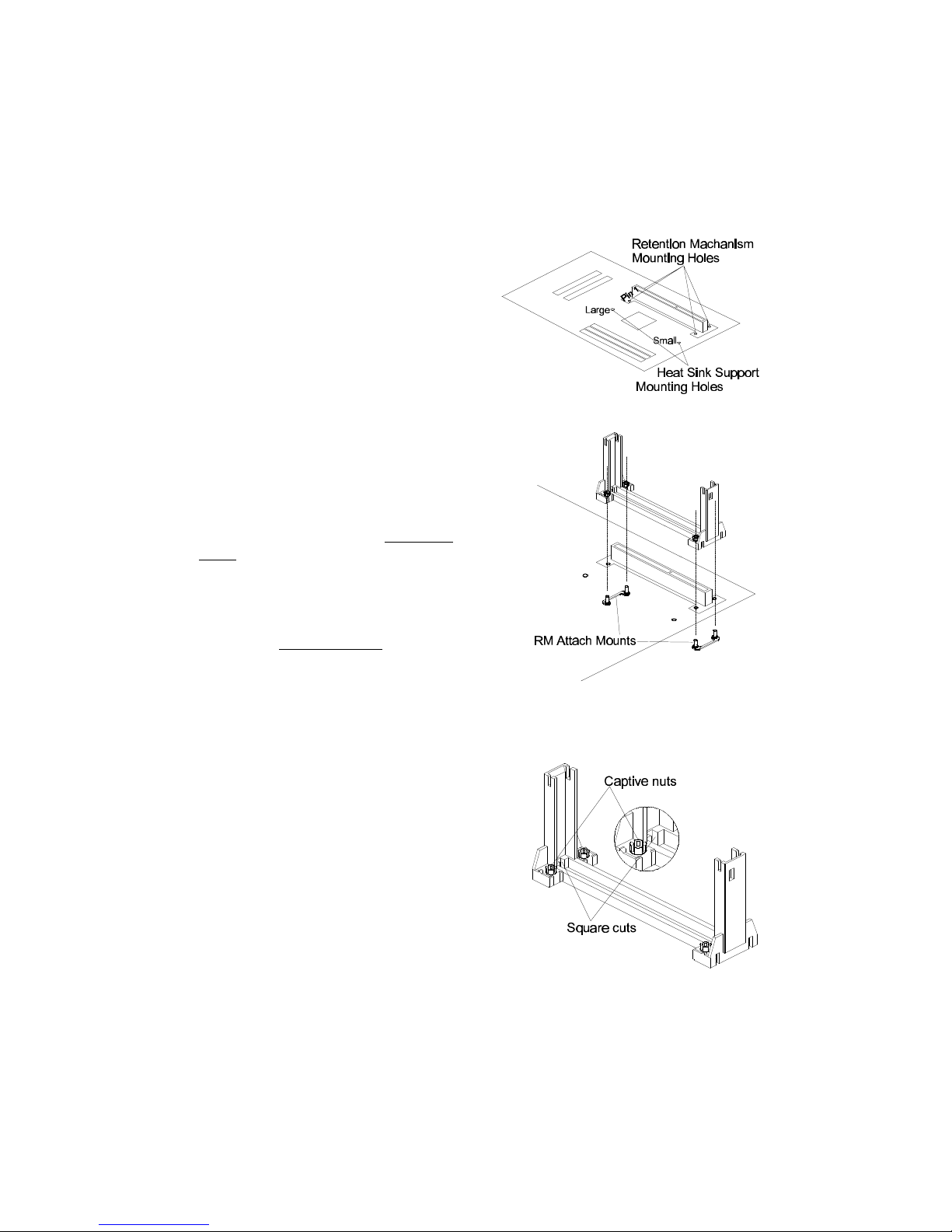
What does the RM (Retention Mechanism) consist of
Pentium II processor requires the Retention Mechanism (RM) and optional Heat Sink
Support (HSS) to hold the base processor in the S.E.C. cartridge.
Following installation procedure will display how to install these mechanism.
Retention Mechanism package consists of 2 separate parts and optional Heat Sink Support
consists of 3 separate parts.
Normally, depend on the type of heat sink, Heat Sink Support is not always available. For
some heat sink attached on pentium II processor might not fit to install the Heat Sink
Support. The introduction of Heat Sink Support installation on this manual only for your
reference.
Retention Mechanism (RM) Plastic Guide with captive nuts that hold the
S.E.C. Cartridge in the Slot1 connector.
(Refer to Figure 2-3)
RM Attach Mount (RMAM) Bolt/Bridge assemblies inserted up through
the bottom of the mainboard. Then secures the
RM to RMAM (two RMAM required per RM).
(Refer to Figure 2-4)
Heat Sink Support Base (HSSBASE) Plastic support bar mounted to the mainboard
under the ATX heat sink.
(Refer to Figure 2-5)
HSS Pin (HSSPIN) Plastic pins inserted through the HSSBASE to secure
it to the mainboard (two required per Assembly).
(Refer to Figure 2-6)
HSS Top Bar (HSSTOP) Plastic bar that clips onto the HSSBASE
through the fins on the ATX heat sink.
(Refer to Figure 2-7)
Figure 2-3
Figure 2-4
Figure 2-5
Figure 2-6
Figure 2-7
10
Install the Retention Mechanism and Heat Sink Support
Place the mainboard on a workbench (not in a chassis). Be sure that the mainboard is bare
(that is, no DIMMs, cables, or cards are installed).
Figure 2-9
Install the Retention Mechanism :
1. Finds out the Retention Mechanism (RM)
Mounting Holes and "Pin 1" mark of Slot 1
on HOT-679 main board. (Refer to Figure
2-8)
2. Install two Retention Mechanism Attach
Mounts (RMAM) with Bolt/Bridge assemblies inserted up through the bottom of the
mainboard. (Notice the RMAM's bridge
orientation as Figure 2-9)
3. Insert the Retention Mechanism (RM)
around the Slot 1. Be sure the Square Cut
Mark of RM (Refer to Figure 2-10) have the
same orientation of Slot 1 pin 1.(Refer to
Figure 2-9)
4. Screw the four captive nuts (Refer to
Figure 2-10) on the RM by a screw drive to
secure RM to two RMANs.
Figure 2-10
Figure 2-8
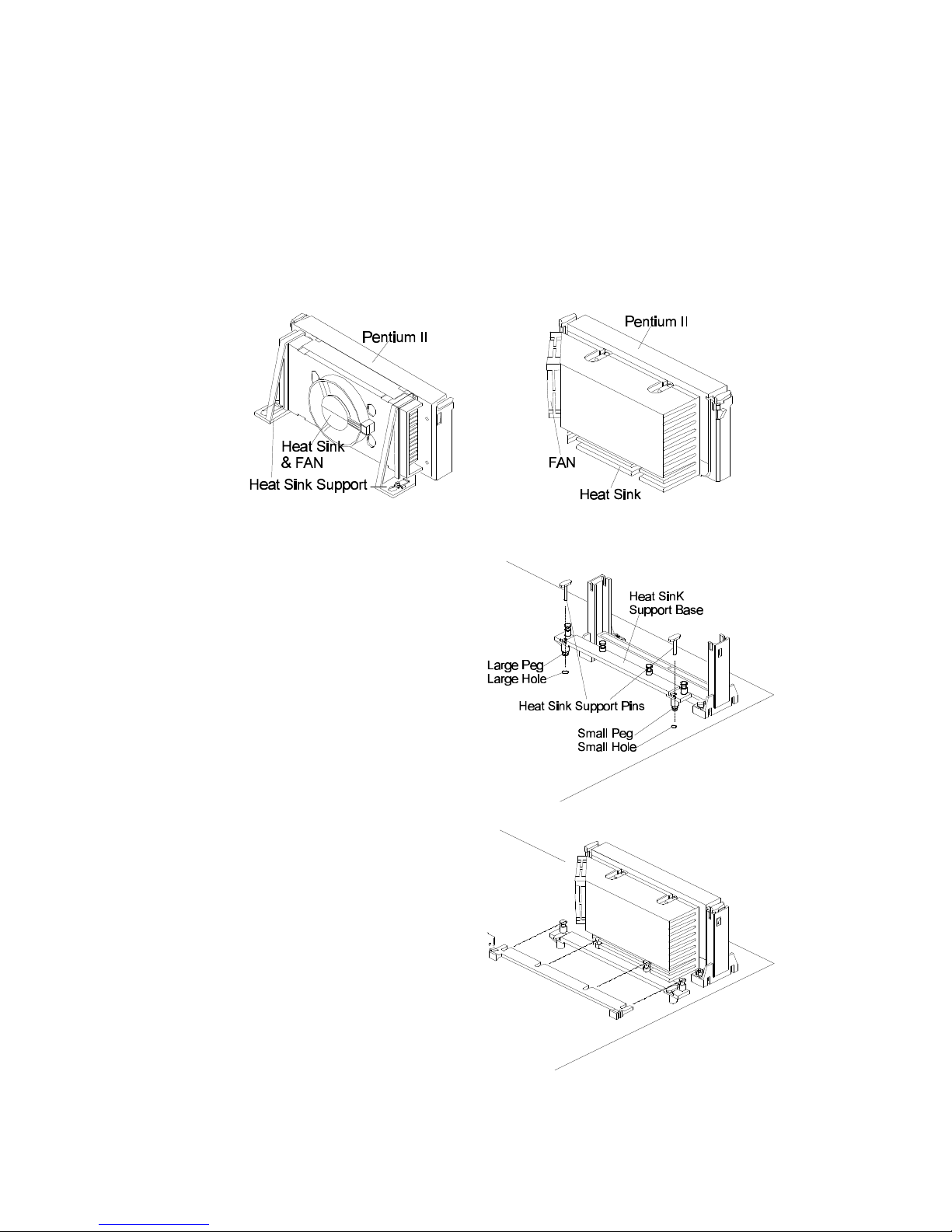
11
1. Finds out the Heat Sink Support (HSS)
Mounting Holes on HOT-679 main
board. Notice that one hole is larger than
the other hole.
2. There are two plastic pegs on the
bottom of Heat Sink Support Base
(HSSBASE) bar. Mount the two black
plastic pegs onto the mainboard. Notice
that one hole and the bar of one peg are
larger than the other hole and peg. (Refer
to Figure 2-13)
3. Insert the Heat Sink Pins (HSSPIN)
through the HSSBASE to secure it to the
mainboard. (Refer to Figure 2-13)
4. Insert the Pentium II into the RM
firmly (Please refer to "Install Pentium II
processor" section), Slide the Heat Sink
Top Bar (HSSTOP) on the supports
forward to clip onto the HSSBASE
through the fins of Heat Sink. (Refer to
Figure 2-14)
Figure 2-11
Figure 2-12
Figure 2-13
Figure 2-14
Install the Heat Sink Support:
Before you install the Heat Sink Support, please check your Pentium II processor, if you have
an Intel boxed processor ( Refer to Figure 2-11), you can ignore this section. In Intel boxed
processor kit, it will includes it's own Heat Sink Support accessories and install manual, you
can Install the Heat Sink Support onto the mainboard by following the Intel processor kit's
instructions.
Figure 2-12 shows the OEM type Pentium II processor with active heat sink.

12
Install Pentium™ II Processor
Push the latches on the processor toward the center of the processor until they click into place.
Hold the processor so that the fan shroud is facing toward the Heat Sink Support Base bar on
the mainboard. Slide the processor into the Retention Mechanism. Ensure that the alignment
notch in the processor fits over the plug in Slot 1. Push the processor down firmly, with even
pressure on both sides of the top, until it is seated.
Push the latches on the processor outward until they click into place in the Retention Mechanism. The latches must be secured for proper electrical connection of the processor. Slide the
Heat Sink Top Bar (HSSTOP) on the supports forward to clip onto the HSSBASE through the
fins of Heat Sink. (Also refer to "Install Heat Sink Support" section)
Attach the end of the power cable to the three-pin connector on the mainboard or to the power
cord of ATX power supply (depend on power cable type of Fan/Heat Sink).
Figure 2-15
13
Primary Side
Figure 2-16
Figure 2-18
Non-primary Side
Figure 2-19
Non-primary Side
Figure 2-20
Primary Side
Figure 2-21
Figure 2-22
Figure 2-17
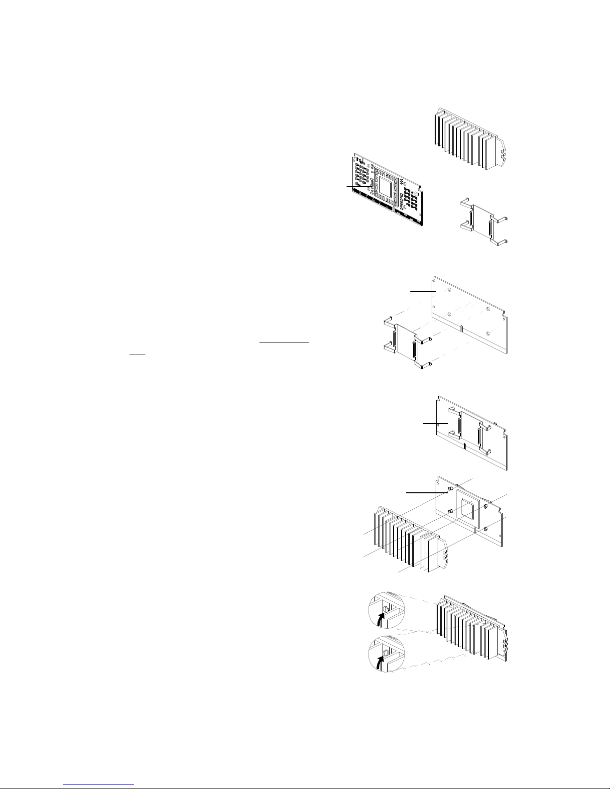
Celeron™ Processor S.E.P.P. Only Retention Mechanism Assembly Procedures
These procedures have been included to help assemble the S.E.P.P.
(Single Edge Processor Package) only Retention Mechanism.
Please follow them exactly:
Procedures
Assemble all parts on a static free bench using
proper operator grounding and an ESD mat.
Carefully insert all four heatsink clip legs into
SEPP. (Figure 2-19)
Clip base must be located on the non-primary
side.(Figure 2-20) FYI - The side of the clip
plate which touches the substrate is covered with
a mylar insulator. This insulator prevents the clip
from shorting lines on the substrate.
Before you fully engage two legs of the clip into
the heatsink (Figure 2-21), make sure you remove
the blue film covering the thermal interface. The
blue film protects the thermal interface from
damage during shipping.
Grasp the heatsink clip assembly between the clip
base and the heatsink. Do not bend or apply
pressure directly to SEPP.
Using a nonmetallic stock or screw driver, push
the remaining two clip legs into the heatsink.
Caution: Take care not to contact passively or
scratch SEPP when using screw driver or bar
stock.
Verify that all the feet on the clip are fully
engaged and seated on the heatsink. (Figure 2-22)
Required Components
SEPP (Figure 2-16)
Heatsink (Figure 2-17)
Heatsink Retention Clip (Figure 2-18)

14
What does the Celeron™ Processor RM consist of
Retention Mechanism for Intel Celeron™ Processor
The Intel Celeron™ Processor requires Retention Mechanism (RM) to hold the base processor
in the Single Edge Processor Package (S.E.P.P). Contact your supplier for the mechanism.
The Retention Mechanism package consists of two separate sets of components.
Each set consists of two RM and two RMAM.
Retention Mechanism (RM) Two Plastic Guides that hold the S.E.P.P in the Slot 1
connector. (Refer to Figure 2-23)
RM Attach Mount (RMAM) Bolt/Bridge assembly inserted up through the.. bottom
of the mainboard, then secures the RM to RMAM
(two RMAM required per RM).(Refer to Figure 2-23)
Figure 2-23
Figure 2-24
Install the Celeron™ Processor RM
Place the mainboard on a workbench (not in a chassis). Be sure that the mainboard is bare
(that is, no DIMMs, cables, or cards are installed).
1. Locate the Retention Mechanism (RM) Mounting Holes of Slot 1 on main board.
(Refer to Figure 2-24)
2. Insert two Retention Mechanisms (RM) face to face on opposite sides of Slot 1.
(Refer to Figure 2-24)
3. Screw the four captive nuts (Refer to Figure 2-24) on the RM with a screw driver to
ecure RM to two RMAMs.

15
Figure 2-26Figure 2-25
Install Celeron™ Processor
Hold the processor unit so that the Heat sink faces toward the DIMM sockets on the mainboard.
Insert the processor into the Retention Mechanism. Press the processor down firmly with even
pressure on both sides of the top until it is seated. (Refer to Figure 2-25 and Figure 2-26)
16
Jumpers
Several hardware settings are made through the use of jumper caps to connect jumper pins on
the main board. The jumper's pin 1 on main board will be on the top or on the left when holding the main board with the keyboard connector away from yourself.
Jumpers with two pins will be shown as for Close (On) and for Open (Off).
To connect the pins, simply place a plastic jumper cap over the two pins.
CPU Clock Speed Selection - JP2 and JP9
HOT-679 featuring CPU Plug & Play function, the user needn't to adjust onboard system clock
and CPU multiplier. When the system power-on first time, BIOS will set CPU clock
speed to 233 MHz or 200 MHz (depend on CPU external frequency) automatically. If
your CPU speed higher than 233 MHz, you only have to entry BIOS to set CPU speed to the
higher one.
HOT-679 mainboard features a clock generator to provide adjustable system clock frequency.
JP2 is a 6-pin jumpers which determine the system clock frequency 66 MHz to 133 MHz.
CPU Plug & Play function is supported by 66MHz / 100MHz.
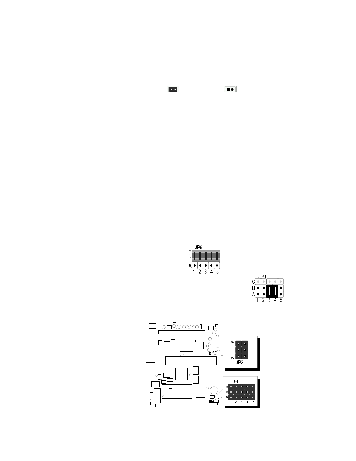
HOT-679 mainboard provides Jumper group of JP9 to figure the CPU core clock multiplier.
By inserting mini jumpers on MANUAL group, the user can figure the Host Bus Clock/CPU
Core Clock ratio (multiplier) manually.
CPU Plug & Play function is supported when an Jumper Pack inserted on
AUTO group.
Listed diagrams on right side show the sample position on jumper group of JP9:
1) Setting CPU Clock from BIOS
- jumper pack on Row B-C group.
(Factory default)
2) Adjust multiplier manually from hardware
- removeing jumper pack from Row B-C group and inserting
mini jumpers on Row A-B group, multiplier set to 5X manually.
Figure 2-27 shows the position of JP2 and JP9 on the mainboard.
Figure 2-27
17
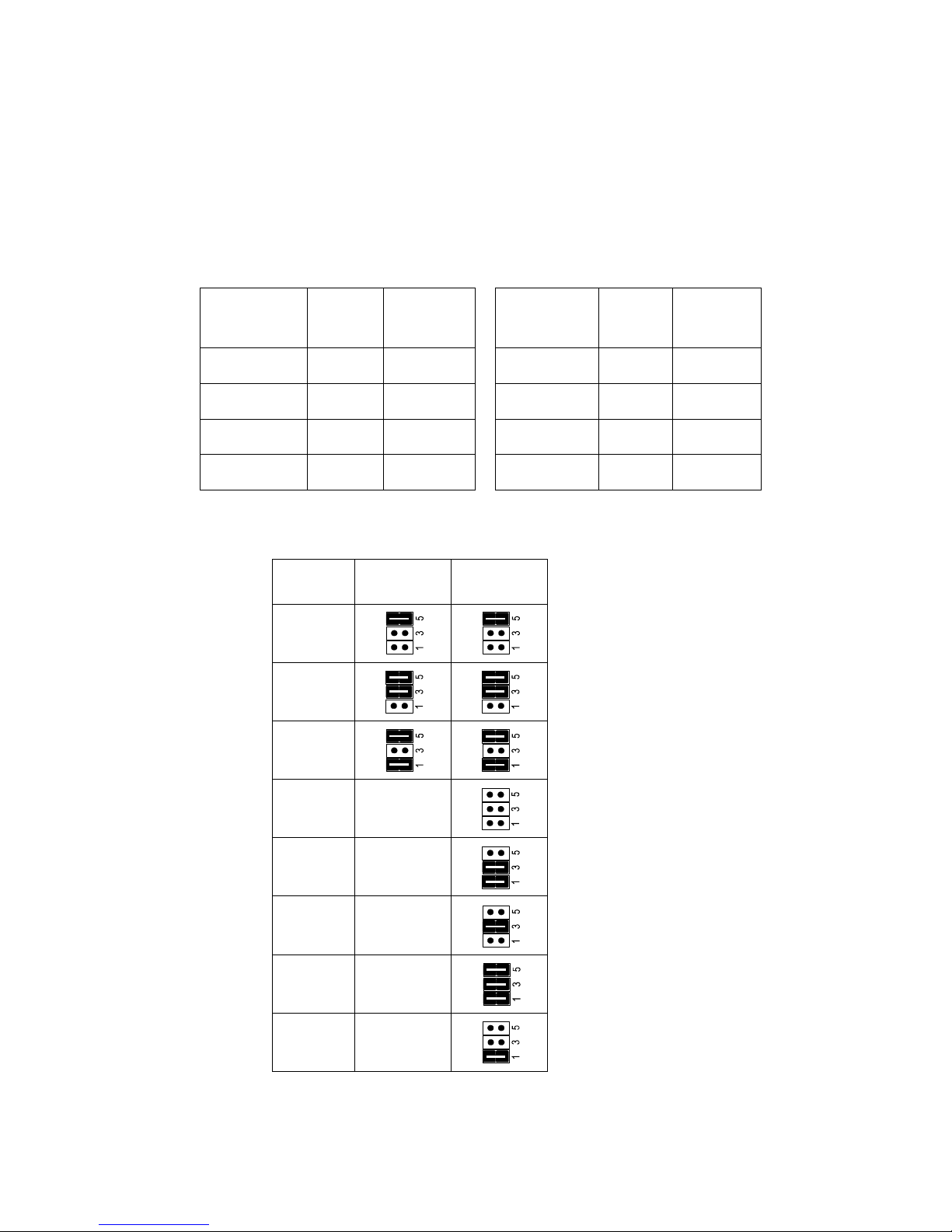
CPU
Host Clock
JP2
66MHz based
processor
JP2
100MHz based
processor
66 MHz
75 MHz
83 MHz
100 MHz
(Default)
N/A
103 MHz N/A
112 MHz N/A
124 MHz N/A
133 MHz N/A
Table 2-2
CPU Clock Configuration Table (Table 2-1) shows the Celeron 233MHz ~ 333MHz and
Pentium II 350MHz ~ 500MHz quick setting on the mainboard.
Table 2-2 shows the adjustable CPU Host Clock on jumper JP2.
Table 2-3 shows the adjustable CPU Clock Ratio on jumper group JP9.
Pentium II
/Celeron
Processor
System
Clock
Multiplier
233 MHz 66 MHz 3.5
266 MHz 66 MHz 4
300 MHz 66 MHz 4.5
333 MHz 66 MHz 5
Pentium II
Processor
System
Clock
Multiplie r
350 MHz 100 MHz 3.5
400 MHz 100 MHz 4
450 MHz 100 MHz 4.5
500 MHz 100 MHz 5
Table 2-1
CPU Configuration Table
CPU Host Clock Configuration Table
 Loading...