

SHURflo 3200 Installation, Operation & Repair Manual
Warranty on SHURflo Macerator Pumps
DO NOT SHIP MACERATOR PUMPS TO SHURFLO PUMP MANUFACTURING COMPANY! Under no
circumstance will Macerator Pump returns be accepted at SHURflo Pump Co., Cypress, Elkhart or Sussex,
England for any reason. All returns must be taken to an authorized SHURflo dealer/marine store for replacement.
SHURflo warrants to the original purchaser of its products (the “Purchaser”) that such products will be free from
defects in material and workmanship under normal use for the period of one (1) year for all products except:
accessories will be free from defects in material and workmanship under normal use for the period of ninety (90)
days. In addition, SHURflo warrants to the purchaser all stainless steel pump manifolds will be free from defects in
material and workmanship under normal use and from damage resulting from environmental conditions for the life
of the pump.
“Normal use” does not include use in excess of recommended pressures, vacuums and temperatures, or use
requiring handling of fluids not compatible with component materials, as noted in SHURflo product catalogs,
technical literature, and instructions. This warranty does not cover freight damage, freezing damage, normal wear
and tear, or damage caused by misapplication, fault, negligence, alterations, or repair that affects the performance
or reliability of the product.
THIS WARRANTY IS EXCLUSIVE. SHURflo MAKES NO OTHER WARRANTY, EXPRESS OR IMPLIED,
INCLUDING BUT NOT LIMITED TO ANY WARRANTY OF MERCHANTABILITY OR FITNESS FOR A
PARTICULAR PURPOSE.
THIS IS THE EXCLUSIVE REMEDY FOR ANY BREACH OF WARRANTY. IN NO EVENT SHALL SHURflo BE
LIABLE FOR ANY INCIDENTAL OR CONSEQUENTIAL DAMAGES OF ANY KIND, WHETHER FOR BREACH
OF ANY WARRANTY, FOR NEGLIGENCE, ON THE BASIS OF STRICT LIABILITY, OR OTHERWISE.
SHURflo reserves the right to request a Material Safety Data sheet from the Purchaser for any pump or product
SHURflo deems necessary. SHURflo reserves the right to “disposition as scrap” pumps or products returned which
contain unknown substances, or to charge for any and all costs incurred for chemical testing and proper disposal
of components containing unknown substances. SHURflo requests this in order to protect the environment and
personnel from the hazards of handling unknown substances.
SHURflo may request additional information, and may require a sketch to illustrate the problem.
Contact the closest factory with questions.
ISO Certified Facility
SHURflo reserves the right to update specifications, prices, or make substitutions.
SHURflo, LLC
5900 Katella Ave.
Cypress, CA 90630
(800) 854-3218 (562) 795-5200
FAX (562) 795-7564
Shipping/UPS: 5900 Katella Ave. Bldg. C
Cypress, CA 90630
SHURflo, LLC East
52748 Park Six Court
Elkhart, IN 46514-5427
(800) 762-8094
(574) 262-0478
FAX (574) 264-2169
© 2001-2005
SHURflo Ltd. Europe, Middle East.
Unit 5 Sterling Park
Gatwick Road, Crawley
West Sussex, RH10 2QT
United Kingdom
+44 1293 424000
(800) 854-3218
FAX +44 1293 421880
911-566-G © August, 2004 -2005 page 4 of 4
Model 3200 Macerator Pump
Installation, Operation & Repair Manual
page 1 of 4
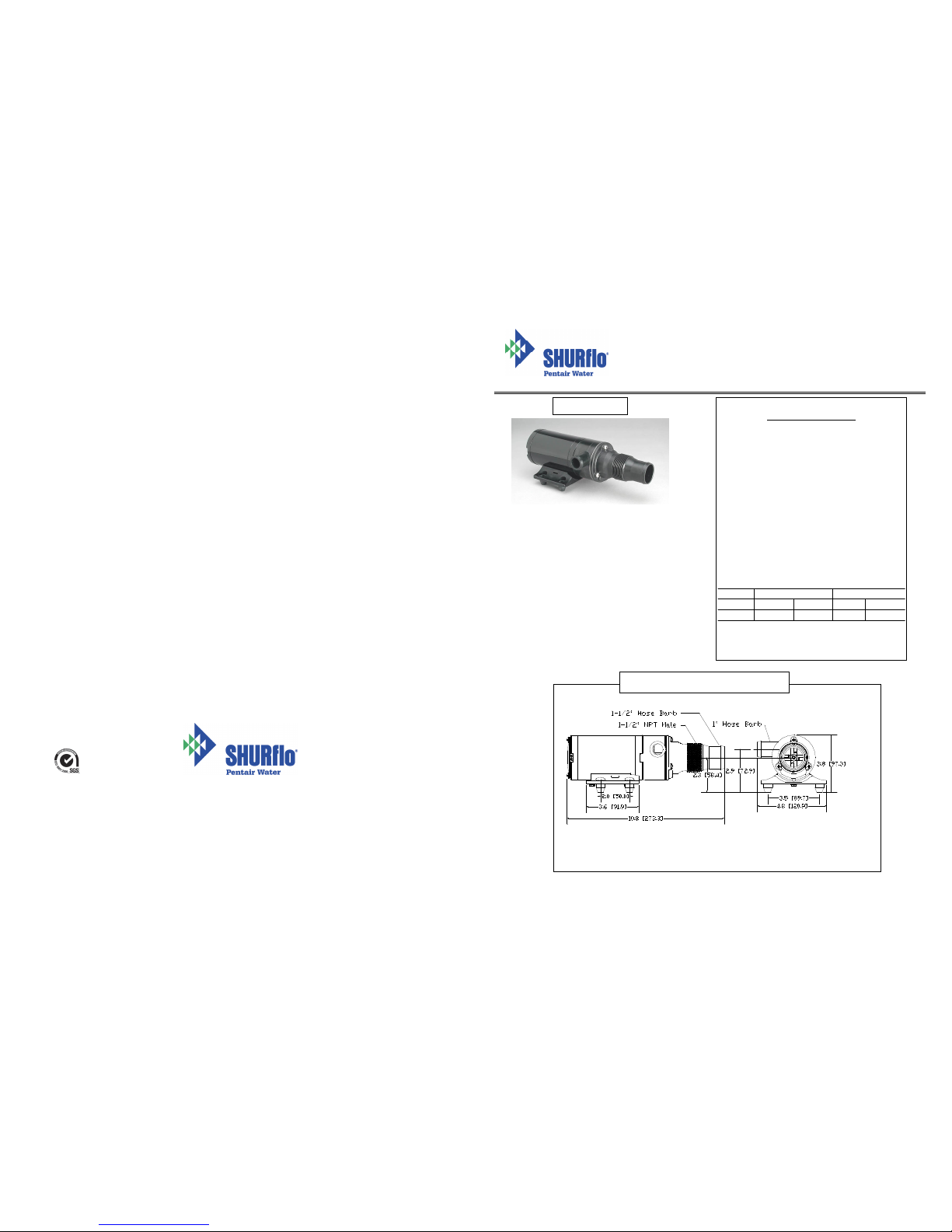
Product Specifications
Motor: Seamless can motor, 1/8 hp
Thermally protected
Lead wires: 14 GA
Fuse: See motor label for fuse size
Pump Type: Flexible impeller
Duty Cycle: Intermittent duty only
Ports: Inlet: 1-1/2” hose barb &
1-1/2” NPT Male
Outlet: 1” hose barb
Impeller: Globe-Blue
Blade: 316 stainless “Double-cut”
Dimensions: See drawing
Weight: 5 lbs.
Approvals: UL ignition protected, ISO 8846
CSA, CE styles available
Typical Flow: Dependent on fluid viscosity
Chart below based on water
Head
Flow gpm[lpm]
Max DC Amps
Ft [m]
12 V
24V
12V
24V
0 [0]
13 [49]
13 [49]178
Maximum Operating Head = 30 feet
SHURflo’s macerator pump is designed to
empty marine and RV holding tanks of normal
waste. It is also an excellent choice for
emptying fish boxes of scales and residual
waste. A flow rate of up to 13 gallons per
minute conveniently empties any tank in
minutes. The unique dual-cut blade design
ensures waste is ground up thoroughly. The
pump is self-priming to a five foot lift when
impeller is wet, four foot lift when impeller is
dry, but for optimum performance and life, it
should be mounted as close to the tank as
possible. Marine pump out must be in
proper discharge zones only. This macerator
will not handle hard objects, rags, or feminine
Typical Dimensional Drawing
Typical Pump

Operation: INTERMITTENT DUTY ONLY!
Pump switch must be near pump and tank so operator can hear pump running.
Make sure shut-off valve to pump and dump valve [if equipped] are both open. Turn on momentary switch
and pump out tank. When tank is empty, pump will get louder with a high pitch sound. Immediately turn
pump off, or damage to impeller and housing will occur. Do not run pump dry for more than 15 – 20
seconds. Flush tank and pump with water after each use. This macerator will handle normal waste,
tissues, cigarettes, fish scales, etc. It is not designed to handle large hard objects such as large bones or
fruit pits.
Periodic Maintenance and Storage: Flush with water after each use. Check wire connections
occasionally. After periods of non-use, impeller can stick. To loosen, open rear shaft cover and turn motor
shaft clockwise with a flat tip screwdriver. Then replace shaft cover. For extended periods of non-use,
pump impeller can be lubricated by running a small amount of mineral oil through holding tank system.
Electrical Connections
WARNING: If the pump is operated in an area containing flammable vapors, the wire leads must be joined by
insulated mechanical locking connectors. Loose or inadequate wire connections can spark, resulting in an
explosion resulting in property damage, injury, or death. All electrical installations should be done by a qualified
electrician.
Pump must be protected with proper size fuse as specified on the motor label.
Pump should be operated on a separate circuit.
Pump should be connected to properly sized momentary switch. This prevents pump from damage due to dry run
condition.
Switch should be near pump. This will allow operator to hear change in pump sound when tank is empty.
NOTE: For proper operation motor must rotate counterclockwise when viewed from pump end.
12 Volt System Min. Wire Size (20 Amps)
Total Wire Length * 3% Drop 10% Drop
feet [m] GA GA
1-10 [.3-3] #10 #16
11-20 [3.3-6] #8 #14
21-30 [6.4-9.1] #6 #12
30-60 [9.1-18.2] #4 #10
*length from power source to motor
and back to ground.
Plumbing Connections
Pump should be mounted as near as possible to tank to minimize dry run. Pump is self-priming to a five-foot lift
when impeller is wet, four foot lift when impeller is dry. Pump is more efficient if mounted near the holding tank.
Installations should be done by qualified marine tech.
INLET: Always install pump with a shut-off valve between pump and holding tank.
Hose: Use 1-1/2” ID [non-collapsible vacuum rated] hose on inlet [suction] side. Use stainless steel hose
clamps on all sanitation connections.
Flange: To mount to 1-1/2” female flange, inlet barb must be cut off just before threads. Seal threads and
hand tighten.
Warning: Any air leak on inlet side can cause pump to run dry and can damage
impeller and impeller housing. Check all inlet side connections, even
those on deck plates. All runs should be smooth with no kinks or sharp
angles.
OUTLET: Use 1” minimum ID hose on discharge side of pump. Connect to thru-hull fitting above highest
heeled point above waterline. Vented loop installations must vent at least 10” above highest
heeled point above waterline. Use stainless steel hose clamps on all sanitation connections.
Part and Kit Lists
Item
Description
Qty.
1
Cover Screw
3
2
Cutter Housing
1
3
O-Ring
1
4
Hex Nut
1
5
Top Cutter Blade
1
6
Bottom Cutter Blade
1
7
Top Wear Plate
1
8
Gasket
1
9
Impeller
1
10
Bottom Wear Plate
1
11
Impeller Housing
1
12
Shaft Seal
1
13
Slinger
1
14
Motor Assembly
1
15
O-Ring
1
16
Rear End Shaft Cover
1
17
End Cap Screw
2
18
Baseplate Assembly
1
19
Hex Bolt
2
Maintenance: Turn off all power!
Rear end cap/ motor shaft slot access:
Loosen end cap screws (17). Rotate shaft cover (16) to access
slot on motor shaft.
Pump disassembly:
Remove 3 cover screws (1). Remove cutter housing (2) and oring (3). Remove hex nut (4) and cutter blades (5) & (6). It
may be necessary to hold the motor shaft steady. Insert a
screwdriver into slot on motor shaft (see slot access above),
or slip a thin wrench (9/32” [7mm]) behind blades onto flat of
motor shaft. Remove top wear plate (7), gasket (8), impeller
(9) and bottom wear plate (10). Remove impeller housing
(11) and shaft seal (12). It is not necessary to remove slinger
(13).
Pump reassembly:
Make sure slinger (13) is on shaft. Make sure shaft seal (12)
is inserted properly into rear of impeller housing (11). Slide
impeller housing (11) onto motor shaft. Seat bottom wear
plate (10) into housing. Twist impeller (9) onto shaft and
into housing with a counterclockwise motion. Install gasket
(8) and top wear plate (7). Install cutter blades (6) & (5) with
tab on bottom blade aligned with motor shaft flat. Secure
motor shaft with screwdriver or wrench (9/32”) [7mm] and
tighten hex nut (4). Position o-ring (3) and cutter housing (2)
in place, and install cover screws (1).
Α Maintenance Tip!
Loosen stuck impeller by turning
motor shaft clockwise from rear
with a flat-tipped screwdriver.
1
2
4
537
1411198121096181315
16
17
Exploded View
Kit Name Kit # Kit Items
Impeller 94-571-00 8, 9
Pump Head 94-570-00 3, 7 - 13
Electrical Installation Checklist
√ Separate circuit from power source
√ Proper size momentary switch mounted near pump
√ Proper wire size to length
√ Proper fuse size and type
√ Insulated wire connectors
page 3 of 4
page 2 of 4
 Loading...