

Page 1
PGXD Wireless System
Shure PGXD Wireless
PGXD sans fil de Shure
Shure PGXD Sem Fio
©2010 Shure Incorporated
27A14513 (Rev. 1)
Printed in U.S.A.
Page 2

Page 3
Page 4

Page 5
Page 6
Page 7
PGXD
System Components
PGX Digital Wireless Systems
Offering uniquely tailored wireless solutions for
vocalists, guitarists, and presenters, PGX-Digital
combines the trusted legacy of Shure wired
microphones with state-of-the-art, 24-bit digital
wireless technology to deliver strong, clean RF
performance. The result is wireless audio that
sounds like wired, rock-steady RF signal even at
extended distances, and plug-and-play setup and
operation.
• Professional quality 24-bit digital audio
• Digital RF technology for rock-solid
performance
• Wide variety of rugged and dependable Shure
microphones
• One-touch setup and operation
• Up to 10 hours of battery life (9 hours,
PGXD2)
• Up to 200 foot range (line-of-sight)
• 900 MHz operation—free from white spaces or
DTV interference
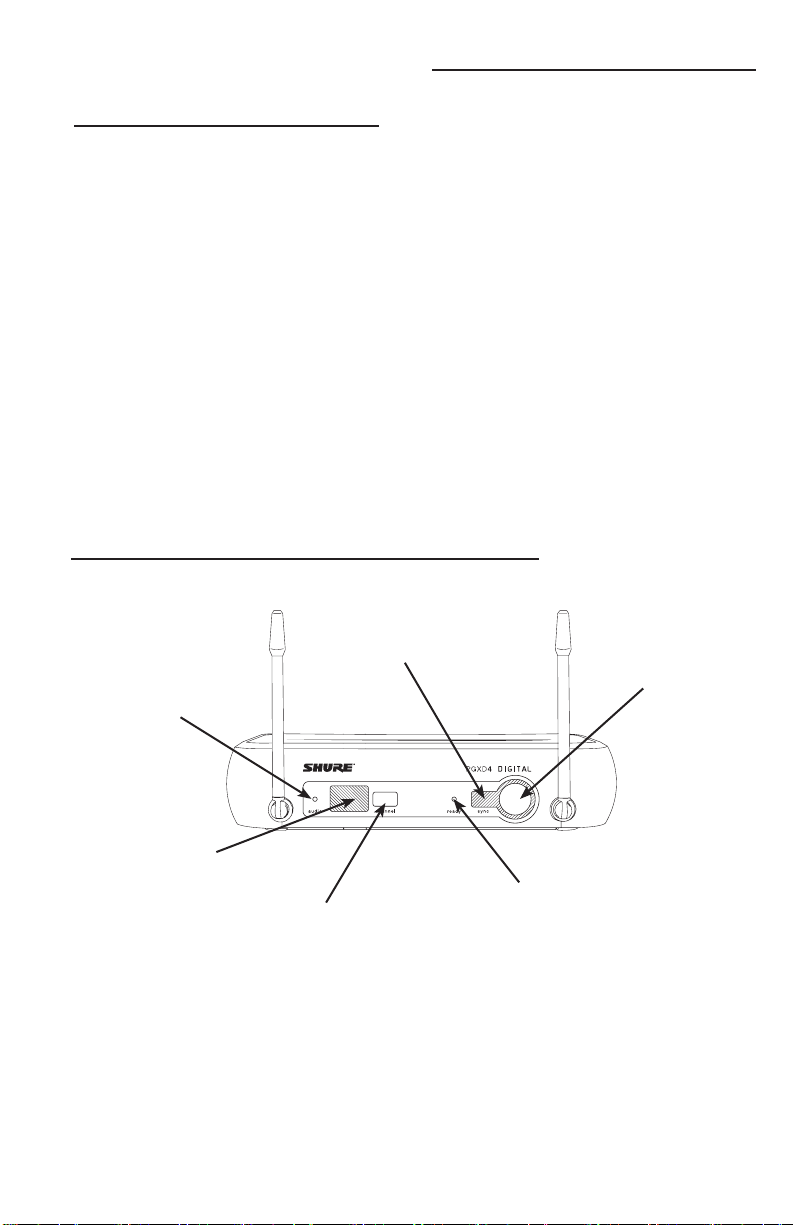
Receiver Controls and Connectors
PGXD4
① audio LED
Indicates strength
of incoming audio
signal: green for
normal, amber for
strong and red for
clipping.
⑤ Infrared (IR) port
Sends IR signal to
transmitter for sync.
All systems include
• PGXD4 receiver
• 2 AA alkaline batteries
• Power supply
• User guide
Vocalist systems include
• PGXD2 handheld transmitter
• Microphone head (choice of PG58, SM58
SM86, Beta 58A® or Beta 87A*)
• Microphone clip
* Available only in select markets
®
,
Lavalier, Headworn, and Instrument
systems include
• PGXD1 bodypack transmitter
• Microphone (choice of WL93, WL185, PG30 or
Beta 98H/C)
Guitar systems include
• PGXD1 bodypack transmitter
• 1/4” to mini 4-pin guitar cable
(WA302)
⑥ sync button
Press to
synchronize
transmitter with
receiver group
and channel
settings.
② LED Screen
Displays group and
channel setting.
See “Single System
Setup” for details.
③ channel button
Changes group and
channel setting.
See “Single System
Setup” for details.
④ ready LED
Indicates system ready and receiving
an RF signal from the transmitter.
Also indicates battery level of the
transmitter:
• Green = transmitter battery level
normal
• Red = low battery (typically less
than 60 minutes with alkaline
batteries)
Note: with NiMH rechargeable batteries, when the indicator turns red there
will be little to no remaining life.
Page 8
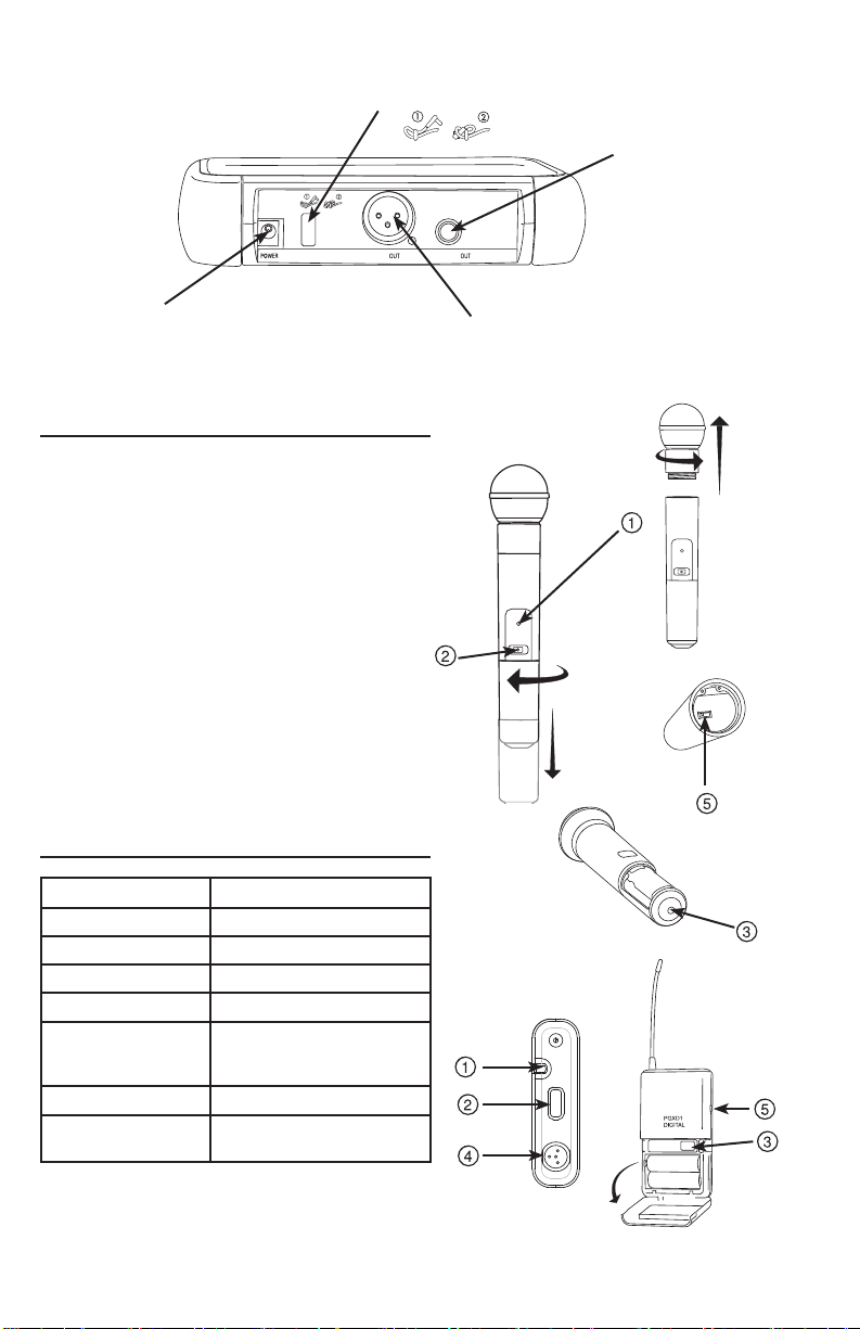
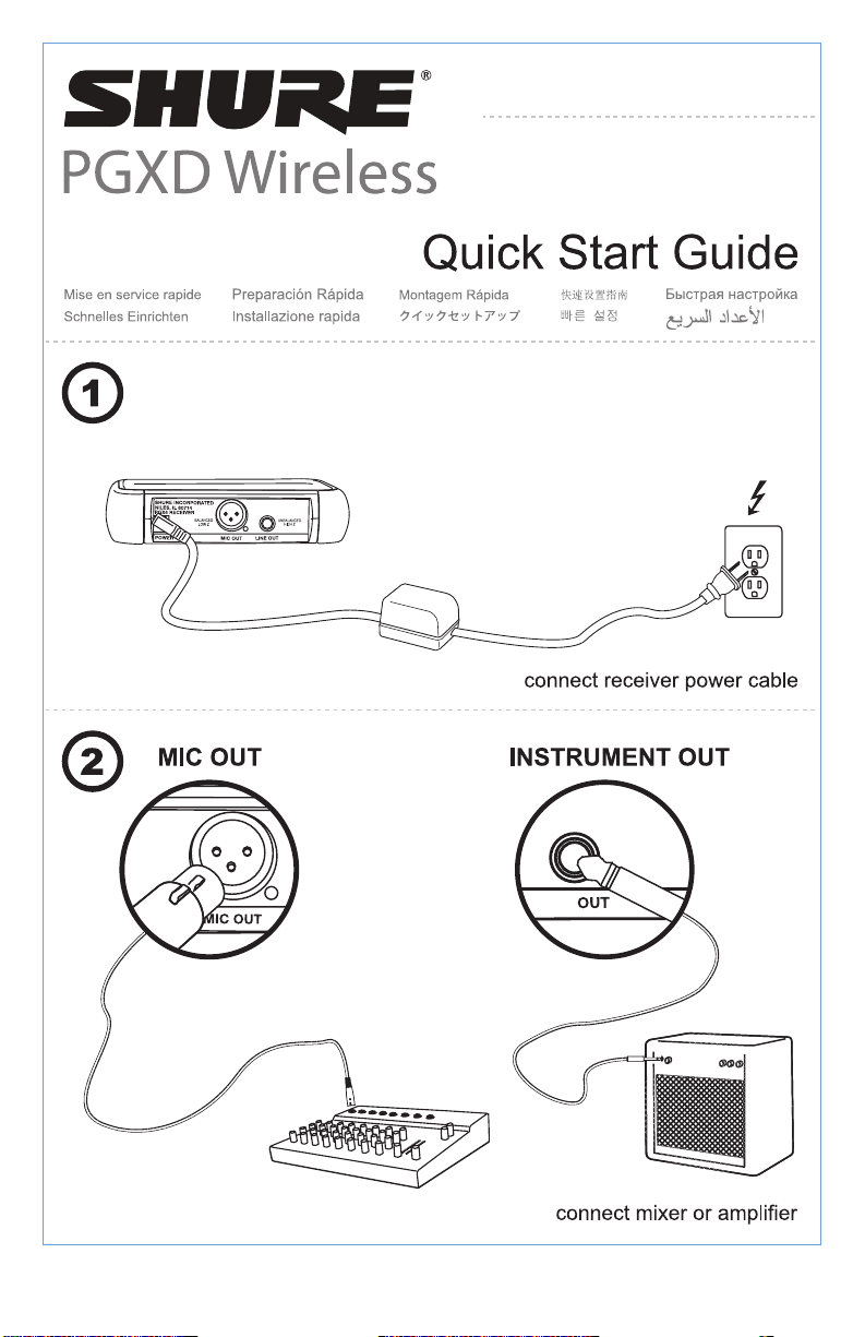
⑧ Adapter cord tie-off
INSTRUMENT
MIC
⑩ 6.35 mm (1/4”) instrument
level output jack
⑦ AC adapter jack
⑨ XLR microphone output jack
Transmitter Controls and Connectors
① Indicator LED
Displays battery level, mute, and IR transmission
status (see table).
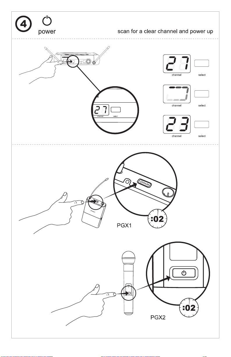
② Power / Mute Switch
Press to mute or unmute. Press and hold to power
on or off.
③ Infrared (IR) port
Receives infrared beam to synchronize frequencies.
When using multiple systems, only one
transmitter IR port should be exposed at a time.
④ 4-Pin Microphone Input Jack
⑤ Audio Gain Adjustment
Transmitter Indicator LED
LED Indicator Status
Green Ready
Flashing green Controls locked
Amber Mute on
Solid red Battery power low
Flashing red Batteries dead (change
Rapidly flashing red IR transmission in process
Flashing amber and
red
batteries to power on
transmitter)
Battery power low and mute
on
PGXD2
PGXD
PGXD1
PGXD
BIAS
AUDIO
-10dB
0dB
Page 9
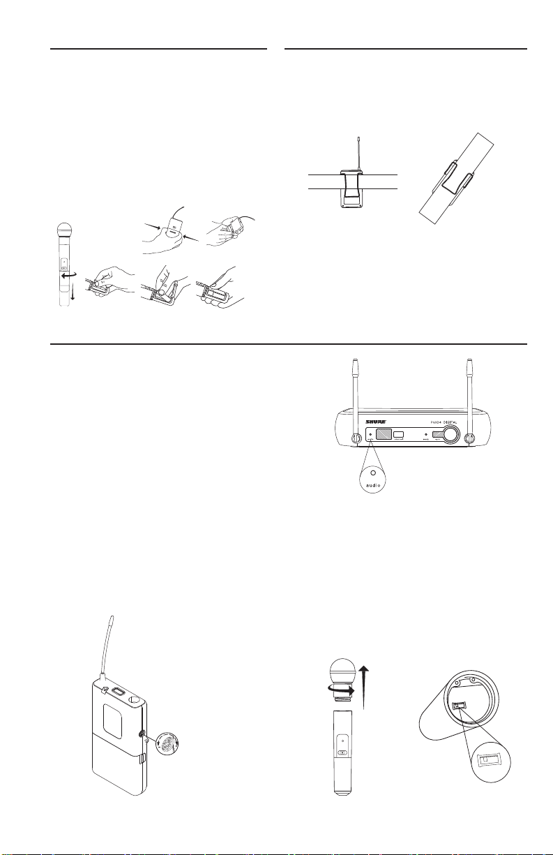
Batteries
Wearing the Bodypack Transmitter
• A fresh set of alkaline batteries lasts up to 10
hours (9 hours, PGXD2).
• The transmitter LED and the receiver ready
LED glow red to indicate low battery (typically
less than 60 minutes remaining).
Clip the transmitter to a belt or slide a guitar strap
through the transmitter clip as shown.
For best results, slide the transmitter until the belt is
pressed against the base of the clip.
• NiMH rechargeable batteries may be used.
However, the low battery indicator functions
differently. When it turns red, there may be little
to no remaining life.
• When the LED flashes red, the batteries must
be replaced to power on the transmitter.
PGXD
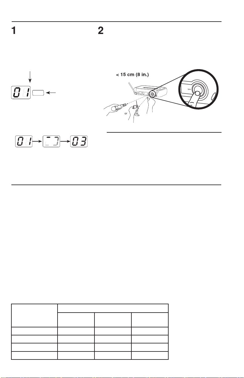
Adjusting Gain
For best audio quality, set transmitter gain so the audio
LED on the receiver flickers green and amber during the
performance. Decrease gain if the signal clips (LED turns
red).
Note: The amber LED may appear to be red when
viewed at an angle. For best results, monitor the LED
from directly in front.
Bodypack Transmitter
The bodypack has 26 dB of audio gain
adjustment.
• Increase gain (clockwise +) for microphones
• Decrease gain (counterclockwise –) for guitars
or high-output instruments
Handheld Transmitter
Access the gain switch by unscrewing the head of
the microphone.
Use the tip of a pen or a small screwdriver to move
the switch.
• 0dB: For quiet to normal vocal performance.
• –10dB: Use only if audio is distorted due to high
vocal levels.
BIAS
AUDIO
-10dB
0dB
PGXD
AUDIO
-10dB
0dB
Page 10
Single System Setup
Scan
Use the scan feature on the receiver to
find a clear channel.
LED screen displays
current channel
press channel
channel
system scans for the channel
with the least interference
button to scan for a
clear channel
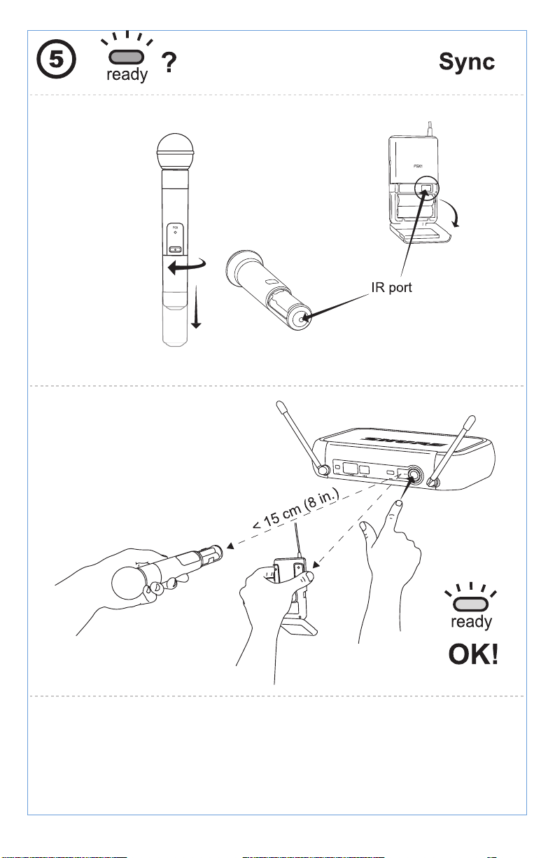
Synchronize
Synchronize the transmitter to the receiver by aligning the
infrared (IR) ports and pressing the sync button. Make sure
the IR ports are closely aligned.
After a successful sync, the transmitter LED momentarily
flashes red and the receiver ready light illuminates.
NOTE: This wireless system may be affected by RF interference when used in proximity to other wireless devices
such as cordless phones, baby monitors, and two-way radios. For best results, use the scan and sync feature before
each use or if you experience problems.
Multiple System Setup
Use the following steps to ensure the best performance when installing multiple wireless systems at the same location.
1. Turn all receivers on and all transmitters off.
Note: Turn on any other digital equipment that could cause interference during
the performance so it will be detected during the frequency scans in the following
steps.
2. Make sure the group number is the same for all receivers (see Manual Group
Selection).
3. Perform a scan using the first receiver.
4. Turn on the first transmitter and sync it to the receiver.
5. Repeat for each system.
• Important: After syncing each transmitter, leave it on so that scans from the other
receivers will not select that channel.
• Be sure only one transmitter IR port is exposed when synchronizing each system.
Compatible Frequencies
When operating multiple systems simultaneously, choose one group from the following
table and set all systems to different channels within that group.
Number of
Systems
Group (by band)
X8 X8A
X8B (Brazil)
(Austrailia)
2 0 to 9 0 to 9 0 to 9
3 3 to 9 3 to 9 3 to 9
4 3 to 9 -- 3 to 9
5 7 to 9 -- --
Page 11
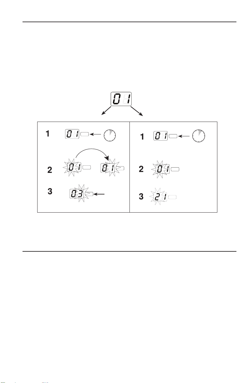
Manual Channel and Group Selection (receiver only)
channel
Using the receiver to scan for a channel is the best way to find the best frequency for your system. However,
for multiple system setup, you may need to manually set the group number.
1. Press and hold the channel button.
2. Hold the button until the channel or group display begins flashing.
3. Release and press the button again to advance the setting.
At the desired channel or group number, wait for the flashing to stop. This activates the new setting.
4. Transfer the new frequency setting to the transmitter using the automatic sync function.
group display channel display
channel
channel
channel
6 s
channel
channel
channel
channel
3 s
Locking and Unlocking Controls
Locking the system controls prevents accidental muting or channel adjustment during performances.
Transmitter
To lock the controls: With the transmitter off,
hold the power button down until the green
LED flashes (~5 seconds)
To unlock the controls: With the transmitter
on, hold the power button down until the green
LED flashes (~5 seconds)
Receiver
To lock the channel: Hold the channel button until
the numbers flash (~10 seconds)
To unlock the channel: Hold the channel button
until the numbers flash (~5 seconds)
Page 12
Troubleshooting
Issue Indicator Status Solution
No sound or faint
sound
Receiver ready LED on Verify all sound system connections
Receiver ready LED off • Turn on transmitter
• Make sure the batteries are installed correctly
• Perform automatic transmitter setup
• Insert fresh batteries
Receiver LED screen off Make sure AC adapter is securely plugged into
Transmitter indicator LED
flashing red
LED screen shows dash
and value
Transmitter LED flashes
red for 7 seconds after
attempting to sync
Noise bursts or
N/A • Change receiver and transmitter to a different
audio dropouts
Distortion Audio LED on receiver
indicates clipping (red)
Distortion increases
gradually over time
Sound level
Transmitter power light
glowing or flashing red
N/A Adjust transmitter gain as necessary
different from
cabled guitar
or microphone
or when using
different guitars
Cannot turn
transmitter on
Transmitter LED slowly
flashing red
Transmitter LED rapidly
flashing red
electrical outlet
Replace transmitter batteries.
Error code displayed. Contact your Shure reseller for
assistance.
Transmitter and receiver incompatible. Contact your
Shure reseller for assistance.
channel
• Remove nearby sources of RF interference such
as cordless or cell phones, computers, wireless
routers, media players, digital signal processors,
and security systems.
• Replace transmitter batteries
• If using multiple systems, change the frequency of
one of the active systems
Reduce transmitter gain
Replace transmitter batteries
Replace transmitter batteries
Contact your Shure reseller for assistance.
50 ohms
XLR Output
50 ohms
1/4” Output
50 ohms
50 ohms
Page 13

SPECIFICATIONS
Working Range (Line of Sight)
60 m (200 ft)
Note: Actual range depends on RF signal absorption, reflection
and interference.
RF Carrier Range
X8: 902–928 MHz
X8A: 915–928 MHz
X8B: 902–907.5 MHz, 915–928 MHz
Note: varies by region
Audio Frequency Response
20–20000 Hz
Note: Dependent on microphone type
System Gain
PGXD2: 0 dB at minimum gain setting, 6.35 mm
(1/4”) connector
–12.5 dB at minimum gain setting, XLR output
PGXD1: –54.5 dBV/Pa at –10 dB gain setting, with
SM58 cartridge, XLR output
Total Harmonic Distortion (Ref. 1 kHz, 6 dB below
input clip)
<0.02%, A-weighted, typical
Dynamic Range
>108 dB, A-weighted
Operating Temperature Range
-18°C (0°F)– +50°C (122°F)
Note: Battery characteristics may limit this range.
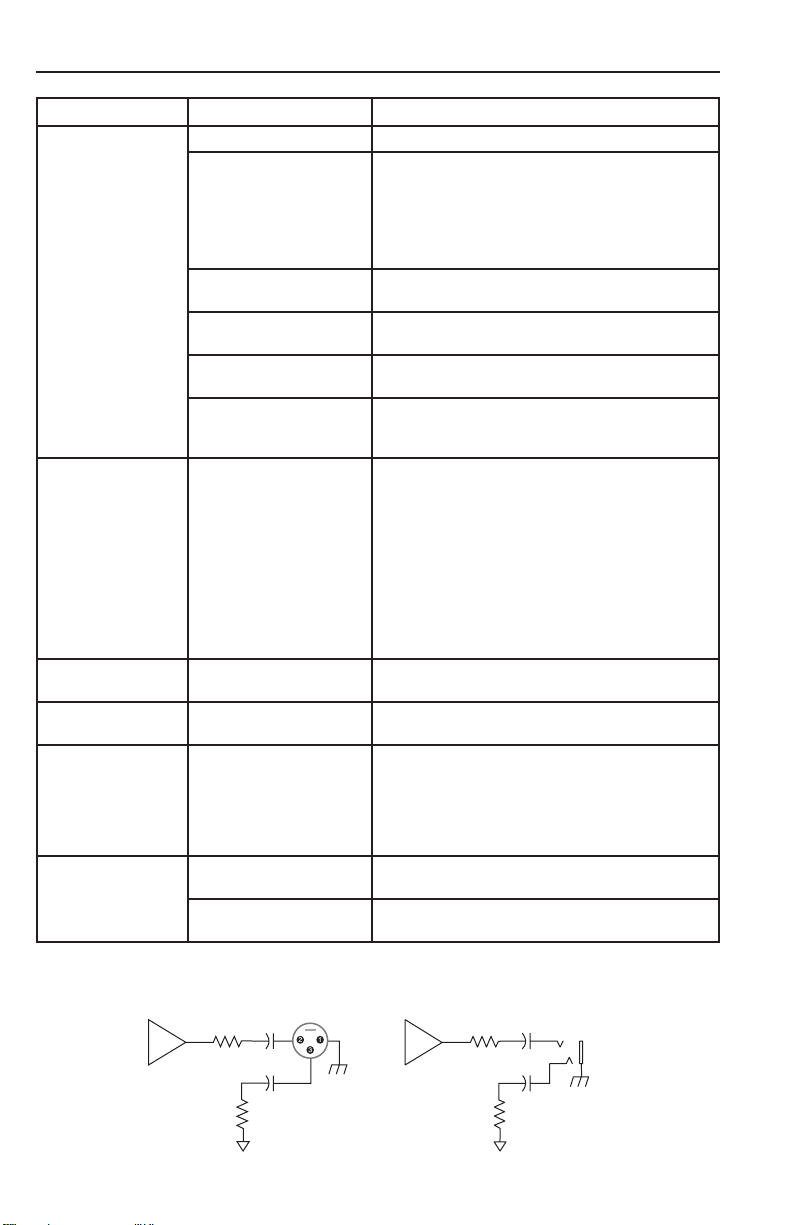
Transmitter Audio Polarity
Positive pressure on microphone diaphragm (or
positive voltage applied to tip of WA302 phone plug)
produces positive voltage on pin 2 (with respect to
pin 3 of low-impedance output) and the tip of the high
impedance 1/4-inch output.
PGXD1 Bodypack Transmitter
Audio Input Level
+10 dBVmaximum, at minimum gain setting
-16 dBVmaximum, at maximum gain setting
Gain Adjustment Range
26 dB
Input Impedance
1 MΩ
RF Output Power
10 mW
varies by region
Pin Assignments
TA4M:
1: ground (cable shield)
2: + 5 V Bias
3: audio
4: Tied through active load to ground (On instrument
adapter cable, pin 4 floats)
Dimensions
108 mm x 64 mm x 19 mm (H x W x D)
Weight
128 g (4.5 oz.)(without batteries)
Housing
Molded polycarbonate case
Power Requirements
2 “AA” size alkaline or rechargeable batteries
Battery Life
up to 10 hours
PGXD2 Handheld Transmitter
Audio Input Level
+5 dBV maximum at -10 dB gain position
–5 dBV maximum at 0 dB gain position
Gain Adjustment Range
10 dB
RF Output Power
10 mW
varies by region
Dimensions
254 mm X 51 mm dia. (10 X 2 in.)
Weight
349 g (12.3 oz.) (without batteries)
Housing
Molded PC/ABS handle and battery cup
Power Requirements
2 “AA” size alkaline or rechargeable batteries
Battery Life
up to 9 hours
PGXD4 Wireless Receiver
Dimensions
40 mm X 181 mm X 104 mm (H x W x D)
Weight
289 g (10.2 oz.)
Housing
ABS
Sensitivity
-102 dBm @ 10
Power Requirements
12–18 V DC @ 150 mA, supplied by external
power supply (tip positive)
Audio LED
Red: 2 dB below clip
Amber: 12 dB below clip
Green: 50 dB below clip
Audio Output
Configuration
Impedance balanced
Audio Output Level (1 kHz tone)
XLR connector: –2.5 dBV (into 3 kΩ load)
6.35 mm (1/4”) connector: +10 dBV (into 10 kΩ
load)
Impedance
XLR: 50 Ω
6.35 mm (1/4”): 50 Ω
Pin Assignments
XLR: 1=ground, 2=hot, 3=cold
6.35 mm (1/4”) TRS: Tip=audio, Ring=no au-
dio, Sleeve=ground
-5
BER
Page 14

CERTIFICATION
PGXD1, PGXD2, PGXD4
This Class B digital apparatus complies with Canadian ICES-003.
Cet appareil numérique de la classe B est conforme à la norme NMB-003 du Canada.
Certified by IC in Canada under RSS-210 and RSS-102. (IC: 616A-PGXD1, 616A-PGXD2, 616A-PGXD4).
PGXD1, PGXD2
Certified under FCC Part 15. (FCC ID: DD4PGXD1, DD4PGXD2).
PGXD4
Approved under the Declaration of Conformity (DoC) provision of FCC Part 15.
Operation of this device is subject to the following two conditions: (1) this device may not cause interference,
and (2) this device must accept any interference, including interference that may cause undesired operation of
the device.
LICENSING INFORMATION
Licensing: A ministerial license to operate this equipment may be required in certain areas. Consult your
national authority for possible requirements. Changes or modifications not expressly approved by Shure
Incorporated could void your authority to operate the equipment. Licensing of Shure wireless microphone
equipment is the user’s responsibility, and licensability depends on the user’s classification and application,
and on the selected frequency. Shure strongly urges the user to contact the appropriate telecommunications
authority concerning proper licensing, and before choosing and ordering frequencies.
INFORMATION TO USER
This equipment has been tested and found to comply with the limits for a Class B digital device, pursuant to
Part 15 of the FCC Rules. These limits are designed to provide reasonable protection against harmful interference in a residential installation. This equipment generates, uses and can radiate radio frequency energy
and, if not installed and used in accordance with the instructions, may cause harmful interference to radio
communications. However, there is no guarantee that interference will not occur in a particular installation. If
this equipment does cause harmful interference to radio or television reception, which can be determined by
turning the equipment off and on, the user is encouraged to try to correct the interference by one or more of
the following measures:
• Relocate the receiving antenna.
• Increase the separation between the equipment and receiver.
• Connect the equipment into an outlet on a circuit different from that to which the receiver is connected.
• Consult the dealer.
Note: EMC conformance testing is based on the use of supplied and recommended cable types. The use of
other cable types may degrade EMC performance.
Changes or modifications not expressly approved by the manufacturer could void the user’s authority
to operate the equipment.
Page 15

PGXD
PGX-Systèmes numériques sans fil
Offrant des solutions sans fil spécialement adaptées aux chanteurs, guitaristes et présentateurs,
PGX Digital combine l’héritage de confiance des
microphones Shure à la technologie numérique
sans fil 24 bits de pointe pour offrir de puissants
signaux HF d’une grande pureté. Le résultat est
la transmission sans fil de signaux audio produisant un son comparable à celui des signaux HF
produits par un système câblé d’une stabilité
sans faille même à de grandes distances, et une
configuration et un fonctionnement plug-and-play.
• Audio numérique 24 bits de qualité
professionnelle
• Technologie HF numérique offrant des
performances sans faille
• Gamme étendue de microphones Shure
robustes et fiables
• Mise en service et utilisation en mode
One-touch
• Jusqu’à 10 heures d’autonomie des piles
• Jusqu’à 91 m (300 pi) de portée (ligne de
visée)
• Fonctionnement à 900 MHz—à l’abri des vides
ou des parasites de télévision numérique
Composants des systèmes
Tous les systèmes
comprennent
• Récepteur PGXD4
• 2 piles alcalines AA
• Bloc d’alimentation
• Guide d’utilisation
Les systèmes pour chanteur comprennent
• Émetteur à main PGXD2
• Capsule de microphone (choix entre PG58,
SM58
• Pince de microphone
*Available only in select markets
Les systèmes à micro-cravate, à
microphone de casque et d’instrument
comprennent
• Émetteur de poche PGXD1
• Microphone (choix entre WL93, WL185, PG30 et
Beta 98H/C)
Les systèmes pour guitare
comprennent
• Émetteur de poche PGXD1
• Câble de guitare de fiche 1/4 po
à mini-connecteur à 4 broches
(WA302)
Commandes et connecteurs du récepteur
PGXD4
① DEL audio
Indique l’intensité du
signal audio d’entrée
: vert pour normal,
jaune pour fort et
rouge pour écrêtage.
⑤ Port infrarouge (IR)
Transmet un signal
IR à l’émetteur pour
synchro.
®
, SM86, Beta 58A®, et Beta 87A*)
⑥ Bouton sync
Appuyer dessus
pour synchroniser
l’émetteur avec
les réglages de
groupe et de
canal.
② Écran à DEL
Affiche le réglage du
groupe et du canal.
Pour plus de détails,
voir « Mise en service
d’un système unique
».
③ Bouton canal
Modifie le réglage
de groupe et de
canal. Pour plus de
détails, voir « Mise
en service d’un
système unique ».
④ DEL ready
Indique que le système est prêt et reçoit un signal
HF de l’émetteur.
Indique également la charge de pile de l’émetteur :
• Vert = charge de pile d’émetteur normale
• Rouge = faible charge de pile (généralement
moins de 60 minutes pour les piles alcalines)
Remarque : dans le cas des piles NiMH rechargeables, la durée utile restante est minime ou nulle
lorsque le témoin s’allume en rouge.
Page 16

⑧ Dispositif de fixation du cor-
don de l’adaptateur
INSTRUMENT
MIC
⑩ Jack de sortie de niveau
d’instrument de 6,35 mm
(1/4 po).
⑦ Jack d’adaptateur c.a.
Commandes et connecteurs
d’émetteur
① Témoin DEL
Affiche la charge de pile, la coupure et l’état de la
transmission IR (voir le tableau).
② Interrupteur marche-arrêt/coupure du son
Appuyer pour activer ou désactiver la coupure du son.
Appuyer et maintenir enfoncé pour mettre sous ou
hors tension.
③ Port infrarouge (IR)
Reçoit le faisceau infrarouge permettant de
synchroniser les fréquences. Lorsque l’on utilise de
multiples systèmes, seul un port IR d’émetteur
doit être exposé à la fois.
④ Jack d’entrée à 4 broches du microphone
⑤ Réglage du gain audio
Témoin DEL d’émetteur
Témoin DEL État
Vert Prêt
Vert clignotant Commandes verrouillées
Jaune Coupure du son activée
Rouge persistant Énergie de la pile presque
Rouge clignotant Énergie des piles épuisée
Clignotement rapide
en rouge
Jaune et rouge
clignotants
épuisée
(changer les piles pour
pouvoir allumer l’émetteur)
Transmission IR en cours
Énergie des piles presque
épuisée et coupure du son
activée
⑨ Jack de sortie de microphone XLR
PGXD2
PGXD
PGXD1
PGXD
BIAS
AUDIO
-10dB
0dB
Page 17

Piles
Port de l’émetteur de poche
• Un jeu de piles alcalines neuves dure jusqu’à 10
heures.
• La DEL de l’émetteur et le témoin DEL ready du
récepteur s’allument en rouge pour indiquer une faible
charge des piles (généralement moins de 60 minutes
restantes).
• Il est possible d’utiliser des piles NiMH rechargeables.
Le témoin de charge insuffisante des piles fonctionne
toutefois différemment. Lorsqu’il s’allume en rouge, il se
peut que la durée utile restante soit minime ou nulle.
• Lorsque la DEL clignote en rouge, les piles doivent être
remplacées pour pouvoir allumer l’émetteur.
PGXD
Réglage du gain
Pour optimiser la qualité audio, régler le gain de
l’émetteur de façon à ce que la DEL audio du récepteur
clignote en vert et en jaune pendant le spectacle.
Réduire le gain si le signal s’écrête (le témoin DEL
s’allume en rouge).
Remarque : la DEL jaune peut sembler rouge quand on
la regarde obliquement. Pour obtenir les meilleurs résultats, surveiller la DEL de face.
Accrocher l’émetteur à une ceinture ou glisser
une sangle de guitare dans l’attache de l’émetteur
comme illustré.
Pour obtenir les meilleurs résultats, faire glisser
l’émetteur jusqu’à ce que la ceinture soit appuyée
contre la base de l’attache.
Émetteur de poche
L’émetteur de poche a une plage de réglage de
gain audio de 26 dB.
• Augmenter le gain (+ vers la droite) pour les
microphones
• Réduire le gain (vers la gauche –) pour les
guitares ou les instruments à sortie élevée
Émetteur à main
Pour accéder à l’interrupteur de gain, dévisser la
capsule du microphone.
Déplacer le sélecteur de l’interrupteur à l’aide d’une
pointe de stylo ou d’un petit tournevis.
• 0 dB : Spectacles vocaux d’ambiance et normaux.
• –10 dB : À utiliser uniquement si l’audio est
distordu à cause de niveaux de voix élevés.
BIAS
AUDIO
-10dB
0dB
PGXD
AUDIO
-10dB
0dB
Page 18

Mise en service d’un système unique
Balayage
Utiliser la fonction de balayage du récepteur pour trouver un canal inutilisé.
l’écran à DEL affiche le
canal actuel
appuyer sur le
channel
le système effectue un balayage
pour trouver le canal présentant le
moins de parasites.
bouton canal pour
rechercher un
canal inutilisé
Synchronisation
Synchroniser l’émetteur et le récepteur en alignant les ports
infrarouges (IR) et en appuyant sur le bouton sync. Veiller
à ce que les ports IR soient étroitement alignés.
Après une synchronisation réussie, la DEL de l’émetteur
clignote brièvement en rouge et le témoin ready du récepteur s’allume.
REMARQUE : Ce système sans fil peut connaître des parasites HF lorsqu’il est utilisé à proximité d’autres appareils
sans fil tels que les téléphones sans fil, les interphones de
surveillance et les radios bidirectionnelles. Pour obtenir les
meilleurs résultats, utiliser la fonction scanner et synchronisation avant chaque utilisation ou en cas de problèmes.
Mise en service de systèmes multiples
Procéder comme suit pour garantir les meilleures performances lors de l’installation de plusieurs systèmes
sans fil au même endroit.
1. Mettre tous les récepteurs en marche et tous les émetteurs sur arrêt.
Remarque : Allumer tout autre appareil numérique susceptible de causer des parasites pendant le spec-
tacle de façon à ce qu’il soit détecté pendant les balayages de fréquences effectués lors des étapes
suivantes.
2. Veiller à ce que le numéro de groupe soit le même pour tous les récepteurs (voir Sélection manuelle de
groupe).
3. Effectuer un balayage à l’aide du premier récepteur.
4. Allumer le premier émetteur et le synchroniser au récepteur.
5. Répéter les étapes précédentes pour chaque système.
• Important : Après avoir synchronisé chaque émetteur, le laisser allumé de façon à ce que les balayages
des autres récepteurs ne sélectionnent pas ce même canal.
• S’assurer que seul un port IR d’émetteur est exposé lorsque l’on synchronise chaque système.
Fréquences compatibles
En cas d’utilisation simultanée de plusieurs systèmes, choisir un groupe sur le tableau
qui suit et régler tous les systèmes à des canaux différents.
Nombre de
systèmes
Groupe (par bande)
X8 X8A
X8B (Brésil)
(Australie)
2 0 à 9 0 à 9 0 à 9
3 3 à 6 3 à 9 3 à 9
4 3 à 6 -- 3 à 9
5 7 à 9 -- --
Page 19

Sélection manuelle de canal et de groupe (récepteur seulement)
channel
Le balayage à la recherche d’un canal à l’aide du récepteur représente le meilleur moyen de trouver la meilleure fréquence pour le système. Il peut toutefois s’avérer nécessaire de définir manuellement le numéro de
groupe pour la mise en service de systèmes multiples.
1. Appuyer sur le bouton canal et le maintenir enfoncé.
2. Maintenir le bouton enfoncé jusqu’à ce que l’affichage de canal ou de groupe commence à clignoter.
3. Relâcher le bouton et appuyer de nouveau dessus pour avancer le réglage.
Une fois le numéro de canal ou de groupe désiré atteint, attendre que le clignotement cesse. Cela active le
nouveau réglage.
4. Transférer le nouveau réglage de fréquence à l’émetteur à l’aide de la fonction de synchronisation
automatique.
affichage de canal
channel
channel
channel
6 s
channel
affichage de groupe
channel
channel
channel
3 s
Verrouillage et déverrouillage des commandes
Le verrouillage des commandes du système empêche de couper le son ou de changer de canal accidentellement durant les spectacles.
Émetteur
Pour verrouiller les commandes : l’émetteur
étant éteint, maintenir enfoncé le bouton de
mise sous tension jusqu’à ce que la DEL
verte clignote (environ 5 secondes).
Pour déverrouiller les commandes :
l’émetteur étant allumé, maintenir enfoncé le
bouton de mise sous tension jusqu’à ce que
la DEL verte clignote (environ 5 secondes).
Récepteur
Pour verrouiller le canal : Maintenir le bouton ca-
nal jusqu’à ce que les numéros clignotent (environ
10 secondes)
Pour déverrouiller le canal : Maintenir le bouton
canal jusqu’à ce que les numéros clignotent (environ 5 secondes)
Page 20

Dépannage
Problème État du témoin Solution
Son faible ou
inexistant
Témoin DEL ready du
récepteur allumé
Témoin DEL ready du
récepteur éteint
Vérifier tous les branchements de la sonorisation
• Allumer l’émetteur
• S’assurer que les piles sont bien en place
• Effectuer la mise en service automatique de
l’émetteur
• Insérer des piles neuves
Écran à DEL du récepteur
éteint
Témoin DEL de l’émetteur
clignotant en rouge
L’écran à DEL affiche un
tiret et une valeur
La DEL de l’émetteur
clignote en rouge
pendant 7 secondes
après une tentative de
synchronisation
Salves de parasites
ou perte de signal
Distorsion Le témoin DEL audio
La distorsion
augmente
graduellement au fur
et à mesure que le
temps passe
Niveau sonore
différent de celui
d’une guitare ou d’un
microphone câblé(e),
ou variable selon les
guitares utilisées
Impossible d’allumer
l’émetteur
S. O. • Faire passer le récepteur et l’émetteur à un
du récepteur indique un
écrêtage (rouge)
Témoin d’alimentation
de l’émetteur allumé ou
clignotant en rouge
S. O. Régler le gain de l’émetteur selon le besoin
DEL de l’émetteur
clignotant lentement en
rouge
DEL de l’émetteur
clignotant rapidement en
rouge
S’assurer que l’adaptateur c.a. est solidement
branché sur une prise électrique.
Remplacer les piles de l’émetteur.
Code d’erreur affiché Demander l’assistance du
revendeur Shure.
Émetteur et récepteur incompatibles. Demander
l’assistance du revendeur Shure.
canal différent
• Éliminer toutes les sources proches de
parasites HF telles que téléphones sans fil
ou cellulaires, ordinateurs, routeurs sans fil,
lecteurs multimédia, processeurs de signaux
numériques et systèmes de sécurité.
• Remplacer les piles de l’émetteur
• Si l’on utilise des systèmes multiples, changer la
fréquence d’un des systèmes actifs
Réduire le niveau de gain de l’émetteur
Remplacer les piles de l’émetteur
Remplacer les piles de l’émetteur
Demander l’assistance du revendeur Shure.
Page 21

Caractéristiques
Plage de fonctionnement (Ligne de visée)
60 m (200 pi)
Remarque : La portée réelle dépend de l’absorption et de la
réflexion des signaux HF, ainsi que des parasites.
Gamme de fréquences porteuses HF
X8: 902–928 MHz
X8A: 915–928 MHz
X8B: 902–907.5 MHz, 915–928 MHz
Remarque : varie suivant la région
Réponse en fréquence audio
20–20000 Hz
Remarque : dépend du type de microphone
Gain du système
PGXD2: 0 dB au réglage de gain minimum,
Connecteur de 6,35 mm (1/4 po)
–12.5 dB au réglage de gain minimum, Sortie XLR
PGXD1: –54.5 dBV/Pa au réglage de gain de –10 dB,
avec capsule SM58, Sortie XLR
Distorsion harmonique totale (Réf. 1 kHz, 6 dB en
dessous de l’écrêtage d’entrée)
<0.02%, pondéré en A, typique
Plage dynamique
>108 dB, pondéré en A
Plage de températures de fonctionnement
-18°C (0°F)– +50°C (122°F)
Remarque : Les caractéristiques des piles peuvent limiter
cette plage.
Polarité audio de l’émetteur
Une pression positive sur le diaphragme du microphone (ou une tension positive appliquée à la pointe
du jack téléphone WA302) produit une tension positive à la broche 2 (par rapport à la broche 3 de la sortie basse impédance) et à la pointe de la sortie haute
impédance de 1/4 po.
Émetteur de poche PGXD1
Niveau d’entrée audio
+10 dBVmaximum, au réglage de gain minimum
-16 dBVmaximum, au réglage de gain maximum au
réglage de gain micro
Plage de réglage de gain
26 dB
Impédance d’entrée
1 MΩ
Puissance de sortie HF
10 mW
varie suivant la région
Repérage des broches
TA4M:
1: masse (blindage du câble)
2: Polarisation + 5 V
3: audio
4: Charge active reliée à la masse (Sur le câble
d’adaptateur d’instrument, la broche 4 est isolée.)
Dimensions
108 mm x 64 mm x 19 mm (H x L x P)
Poids
128 g (4.5 oz.)(sans piles)
Boîtier
Boîtier en polycarbonate moulé
Alimentation
2 piles alcalines ou rechargeables de taille AA
Autonomie des piles
jusqu’à 10 h
Émetteur à main PGXD2
Niveau d’entrée audio
+5 dBV maximum at -10 dB gain position
–5 dBV maximum at 0 dB gain position
Plage de réglage de gain
10 dB
Puissance de sortie HF
10 mW
varie suivant la région
Dimensions
254 mm X 51 mm diam. (10 X 2 po)
Poids
349 g (12.3 oz.) (sans piles)
Boîtier
Poignée et réceptacle des piles en PC/ABS
moulé
Alimentation
2 piles alcalines ou rechargeables de taille AA
Autonomie des piles
jusqu’à 9 h
Récepteur sans fil PGXD4
Dimensions
40 mm X 181 mm X 104 mm (H x L x P)
Poids
289 g (10.2 oz.)
Boîtier
ABS
Sensibilité
-102 dBm @ 10
Alimentation
12–18 V c.c. @ 150 mA, provenant d’un bloc
d’alimentation externe (pointe positive)
DEL audio
Rouge: 2 dB sous le clip
Jaune: 12 dB sous le clip
Vert: 50 dB sous le clip
Sortie audio
Configuration
Impédance symétrique
Niveau de sortie audio (Tonalité de 1 kHz)
Connecteur XLR: –2.5 dBV (dans 3 kΩ de
charge)
Connecteur de 6,35 mm (1/4 po): +10 dBV
(dans 10 kΩ de charge)
Impédance
XLR: 50 Ω
6.35 mm (1/4”): 50 Ω
Repérage des broches
XLR: 1 = masse, 2 = positif; 3 = négatif
TRS 6,35 mm (1/4 po): Pointe = audio, anneau
= non audio, corps = masse
-5
BER
Page 22

HOMOLOGATION
PGXD1, PGXD2, PGXD4
Cet appareil numérique de classe B est conforme à la norme ICES-003 (Canada).
Cet appareil numérique de classe B est conforme à la norme NMB-003 du Canada.
Homologué par IC au Canada selon RSS-210 et RSS-102. (IC: 616A-PGXD1, 616A-PGXD2, 616A-PGXD4).
PGXD1, PGXD2
Homologué selon la partie 15 des réglementations FCC (organisme fédéral réglementant les communications
aux U.S.A.). (FCC ID: DD4PGXD1, DD4PGXD2).
PGXD4
Approuvé selon la déclaration de conformité de la partie 15 des réglementations FCC.
L’utilisation de ce dispositif est assujettie aux deux conditions suivantes : (1) ce dispositif ne doit pas causer
d’interférences et (2) ce dispositif doit accepter toutes les interférences, y compris celles qui pourraient provoquer un fonctionnement non souhaitable de l’appareil.
RENSEIGNEMENTS SUR L’OCTROI DE LICENCE
Autorisation d’utilisation : Une licence officielle d’utilisation de ce matériel peut être requise dans certains
pays. Consulter les autorités compétentes pour les exigences possibles. Tout changement ou modification
n’ayant pas fait l’objet d’une autorisation expresse de Shure Incorporated peut entraîner la nullité du droit
d’utilisation de l’équipement. La licence d’utilisation de l’équipement de microphone sans fil Shure demeure
de la responsabilité de l’utilisateur, et dépend de la classification de l’utilisateur et de l’application prévue par
lui ainsi que de la fréquence sélectionnée. Shure recommande vivement de se mettre en rapport avec les
autorités compétentes des télécommunications pour l’obtention des autorisations nécessaires, et ce avant de
choisir et de commander des fréquences.
INFORMATION À L’UTILISATEUR
Cet équipement a été testé et déclaré conforme aux limites pour les appareils numériques de classe B, selon
la section 15 des règlements de la FCC. Ces limites sont destinées à assurer une protection raisonnable
contre les interférences nuisibles dans une installation résidentielle. Cet équipement produit, utilise et peut
émettre de l’énergie radio électrique et, s’il n’est pas installé et utilisé conformément aux présentes instructions, peut causer des interférences nuisibles aux communications radio. Il n’existe toutefois aucune garantie
que de telles interférences ne se produiront pas dans une installation particulière. Si cet équipement produit
des interférences nuisibles à la réception d’émissions de radio ou de télévision, ce qui peut être établi en mettant l’appareil sous, puis hors tension, il est recommandé à l’utilisateur d’essayer de corriger le problème en
prenant l’une ou plusieurs des mesures suivantes :
• Déplacer l’antenne réceptrice.
• Augmenter l’espacement entre l’équipement et le récepteur.
• Brancher l’appareil sur un circuit différent de celui du récepteur.
• Consulter le revendeur.
Remarque : Les essais de conformité CEM sont basés sur l’utilisation de types de câbles fournis et recom-
mandés. L’utilisation d’autres types de câble peut dégrader la performance CEM.
Tout changement ou modification n’ayant pas fait l’objet d’une autorisation expresse du fabricant
peut entraîner la nullité du droit d’utilisation de l’équipement.
50 ohms
XLR Output
50 ohms
1/4” Output
50 ohms
50 ohms
Page 23

PGXD
Sistemas inalámbricos digitales
PGX Digital
El sistema PGX Digital ofrece soluciones inalámbricas únicas a vocalistas, guitarristas y presentadores. Combina el legado confiable de los
micrófonos alámbricos de Shure con tecnología
inalámbrica moderna de 24 bits para entregar
presentaciones con una señal de RF fuerte y nítida. El resultado es audio inalámbrico que suena
como un cable, señal de RF sólida, a grandes
distancias, y funcionamiento tipo conectar y usar.
• Audio digital de 24 bits de calidad profesional
• Tecnología de RF digital para presentaciones
sólidas
• Amplia variedad de micrófonos Shure
resistentes y confiables
• Configuración y uso de un toque
• Hasta 10 horas de duración de las pilas
• Hasta 300 pies de alcance (trayectoria visual)
• 900 MHz de funcionamiento libre de espacios
blancos o interferencia de DTV
Controles y conectores del receptor
Componentes del sistema
Todos los sistemas incluyen
• Receptor PGXD4
• 2 pilas alcalinas AA
• Fuente de alimentación
• Guía del usuario
Los sistemas para vocalista incluyen
• Transmisor de mano PGXD2
• Opciones de micrófono (PG58, SM58
• Pinza para micrófono
®
Beta 58A
* Available only in select markets
, o Beta 87A*)
Los sistemas de corbata, diadema o
instrumentos incluyen
• Transmisor portátil PGXD1
• Micrófono (WL93, WL185, PG30 o Beta 98H/C)
Los sistemas para guitarra
incluyen
• Transmisor portátil PGXD1
• Cable de guitarra con conector de
1/4 pulg a conector miniatura de 4
clavijas (WA302)
®
, SM86,
PGXD4
① LED de audio
Indica la intensidad
de la señal sonora
entrante: verde para
normal, ámbar para
fuerte y rojo para
limitación.
② Pantalla LED
Visualiza el ajuste de
grupo y canal. Vea
“Preparación de un
sistema sencillo” para
los detalles.
③ botón de canal
Cambia el ajuste de
grupo y canal. Vea
“Preparación de un
sistema sencillo”
para los detalles.
⑤ Puerto infrarrojo
(IR)
Envía una señal IR
al transmisor para la
sincronización.
④ LED de listo
⑥ botón de
sincronización
Presione para
sincronizar el
transmisor con los
ajustes de grupo y
canal del receptor.
Indica que el sistema está listo y recibiendo una
señal de RF del transmisor.
También indica el nivel de carga de las pilas del
transmisor:
• Verde = nivel normal de pilas del transmisor
• Rojo = pilas descargadas (típicamente menos
de 60 minutos con pilas alcalinas)
Nota: con pilas recargables de NiMH, cuando el
indicador se torna rojo queda poca a nada de carga
en las pilas.
Page 24

⑧ Atado de cordón del
adaptador
INSTRUMENT
MIC
⑩ Jack de salida para nivel
de instrumento de 6,35
mm (1/4 pulg)
⑦ Jack para adaptador de CA
Controles y conectores del
transmisor
① LED indicador
Visualiza nivel de carga de las pilas, silenciamiento y
estado de transmisión IR (vea la tabla).
② Conmutador de alimentación/silenciamiento
Presione para activar o desactivar el silenciamiento.
Manténgalo oprimido para encender o apagar la
unidad.
③ Puerto infrarrojo (IR)
Recibe el haz infrarrojo para sincronizar las
frecuencias. Cuando se utilizan sistemas múltiples,
sólo un puerto IR deberá estar descubierto a la
vez.
④ Jack de entrada de micrófono con 4 clavijas
⑤ Ajuste de ganancia de audio
LED indicador del transmisor
Indicadores LED Estado
Verde Listo
Verde destellante Controles bloqueados
Ambar Silenciamiento activado
Rojo constante Pilas descargadas
Rojo destellante Pilas agotadas (cambie
Rojo destellante
rápido
Destellante ámbar
y rojo
las pilas para encender el
transmisor)
Transmisión IR en progreso
Pila descargada y
silenciamiento activado
⑨ Jack de salida de micrófono tipo XLR
PGXD2
PGXD
PGXD1
PGXD
BIAS
AUDIO
-10dB
0dB
Page 25

Pilas
Uso del transmisor portátil
• Un juego de pilas alcalinas nuevas dura hasta 10
horas.
• El LED del transmisor y el LED de listo del
receptor se iluminan de color rojo para indicar que
las pilas están descargadas (típicamente menos
de 60 minutos de vida útil restante).
• Se pueden usar pilas recargables de NiMH. Sin
embargo, el indicador de pilas descargadas
funciona de manera diferente. Cuando se torna
rojo, puede quedar poca a nada de carga en las
pilas.
• Cuando el LED destella de color rojo, hay que
cambiar las pilas para encender el transmisor.
PGXD
Ajuste de la ganancia
Para la mejor calidad del audio, fije la ganancia del transmisor de manera que el LED de audio en el receptor
destelle de color verde y ámbar durante la presentación.
Disminuya la ganancia si la señal se limita (el LED se
torna rojo).
Nota: El LED ámbar se puede ver rojo cuando se mira
en ángulo. Para resultados óptimos, monitoree el LED
directamente de frente.
Enganche el transmisor a un cinturón o deslice
una correa de guitarra a través del gancho del
transmisor, de la manera ilustrada.
Para obtener los mejores resultados, deslice el
transmisor hasta que la correa quede presionada
contra la base del gancho.
Transmisor portátil
El transmisor portátil tiene un ajuste de ganancia
de audio de 26 dB.
• Aumente la ganancia (en sentido horario +)
para micrófonos
• Disminuya la ganancia (en sentido
contrahorario –) para guitarras o instrumentos
con señal de salida con nivel alto
Transmisor de mano
Acceda al interruptor de ganancia desenroscando la
cabeza del micrófono.
Utilice la punta de un bolígrafo o un destornillador
pequeño para mover el interruptor.
• 0 dB: Para vocalistas con voz baja a normal.
• –10 dB: Use sólo si el audio está distorsionado
debido a niveles vocales altos.
BIAS
AUDIO
-10dB
0dB
PGXD
AUDIO
-10dB
0dB
Page 26

Preparación de un sistema sencillo
Exploración
Use la función de exploración en
el receptor para encontrar un canal
despejado.
La pantalla LED
visualiza el canal
actual
presione el botón de
channel
el sistema busca el canal con menos
interferencia
canal para buscar un
canal libre
Sincronización
Sincronice el transmisor con el receptor alineando los puertos infrarrojos (IR) y pulsando el botón de sincronización.
Asegúrese que los puertos infrarrojos están estrechamente alineados.
Después de una sincronización exitosa, el LED del transmisor destella momentáneamente en rojo y se ilumina la luz
de listo del receptor.
NOTA: Este sistema inalámbrico puede ser afectado por interferencia de RF cuando se usa cerca de otros dispositivos
inalámbricos tales como teléfonos inalámbricos, monitores
de niños y radios bidireccionales. Para los mejores resultados, utilice la función de exploración y sincronización antes
de cada uso o en caso de experimentar problemas.
Preparación de sistemas múltiples
Use el procedimiento siguiente para asegurar el mejor rendimiento cuando instale sistemas inalámbricos
múltiples en el mismo lugar.
1. Encienda todos los receptores y apague todos los transmisores.
Nota: Encienda cualquier otro equipo digital que pudiera causar interferencia durante la presentación de
manera que pueda detectarse durante las exploraciones de frecuencia en los pasos siguientes.
2. Asegúrese que el número de grupo es el mismo para todos los receptores (vea Selección manual de
grupo).
3. Efectúe una exploración utilizando el primer receptor.
4. Encienda el primer transmisor y sincronícelo con el receptor.
5. Repita con cada sistema.
• Importante: Después de sincronizar cada transmisor, déjelo encendido de manera que las exploraciones
de los otros receptores no seleccionen ese canal.
• Verifique que sólo un puerto IR de transmisor quede descubierto al sincronizar cada sistema.
Frecuencias compatibles
Cuando use sistemas múltiples de manera simultánea, elija un grupo de la tabla siguiente y fije todos los
sistemas en canales diferentes dentro de ese grupo.
Número de
sistemas
Grupo (por banda)
X8 X8A
X8B (Brasil)
(Australia)
2 0 a 9 0 a 9 0 a 9
3 3 a 6 3 a 9 3 a 9
4 3 a 6 -- 3 a 9
5 7 a 9 -- --
Page 27

Selección manual de grupo y canal (receptor solamente)
channel
El uso del receptor para buscar un canal es la mejor forma de encontrar la mejor frecuencia para su sistema.
Sin embargo, para la preparación de sistemas múltiples, es posible que necesite fijar manualmente el número
de grupo.
1. Presione sin soltar el botón de canal.
2. Mantenga presionado el botón hasta que el indicador de canal o grupo empiece a destellar.
3. Suelte y presione el botón nuevamente para hacer avanzar el ajuste.
En el número de canal o grupo deseado, espere hasta que el indicador deje de destellar. Esto activa el
nuevo ajuste.
4. Transfiera el nuevo ajuste de frecuencia al transmisor utilizando la función de sincronización automática.
indicación de grupo
channel
channel
channel
6 s
channel
indicación de canal
channel
channel
channel
3 s
Bloqueo y desbloqueo de controles
El bloqueo de los controles del sistema impide el silenciamiento o ajuste accidental del canal durante las
presentaciones.
Transmisor
Para bloquear los controles: Con el transmisor
apagado, oprima el botón de alimentación hasta
que el LED verde destelle (~5 segundos)
Para desbloquear los controles: Con el trans-
misor encendido, mantenga oprimido el botón de
alimentación hasta que el LED verde destelle (~5
segundos)
Receptor
Para bloquear el canal: Mantenga oprimido el
botón de canal hasta que los números destellen
(~10 segundos)
Para desbloquear el canal: Mantenga oprimido el
botón de canal hasta que los números destellen (~5
segundos)
Page 28

Localización de averías
Problema Estado del
indicador
No hay sonido o es
débil
Ráfagas de ruido o
cortes de audio
LED de listo del
receptor encendido
LED de listo del
receptor apagado
Pantalla LED del
receptor apagada
El LED indicador del
transmisor destella rojo
La pantalla LED
muestra un guión y un
valor
El LED del transmisor
destella de color rojo
durante 7 segundos
después de intentar la
sincronización
N/C • Cambie el receptor y el transmisor a un canal
Solución
Verifique todas las conexiones del sistema de sonido
• Encienda el transmisor
• Asegúrese que las pilas están instaladas
correctamente
• Efectúe la configuración automática del transmisor
• Inserte pilas nuevas
Asegúrese que el adaptador de CA está bien
enchufado en el tomacorriente
Reemplace las pilas del transmisor.
Se visualiza un código de error. Comuníquese con el
distribuidor de equipos Shure para recibir ayuda.
Transmisor y receptor incompatibles. Comuníquese
con el distribuidor de equipos Shure para recibir
ayuda.
diferente
• Elimine las fuentes de interferencia de RF
cercanas, tales como teléfonos inalámbricos
o celulares, computadoras, encaminadores
inalámbricos, reproductores de sonido,
procesadores de señales digitales y sistemas de
seguridad.
• Reemplace las pilas del transmisor
• Si se utilizan sistemas múltiples, cambie la
frecuencia de uno de los sistemas activos
Distorsión El LED de audio
La distorsión aumenta
gradualmente con el
tiempo
El nivel de sonido es
diferente cuando se
conecta la guitarra
o micrófono con un
cable, o si se usan
guitarras diferentes
El transmisor no
enciende
del receptor indica
limitación (rojo)
La luz de alimentación
del transmisor se
ilumina o destella roja
N/C Ajuste la ganancia del transmisor según sea
El LED del transmisor
destella rojo lentamente
El LED del transmisor
destella rojo
rápidamente
Reduzca la ganancia del transmisor
Reemplace las pilas del transmisor
necesario
Reemplace las pilas del transmisor
Comuníquese con el distribuidor de equipos Shure
para recibir ayuda.
Page 29

ESPECIFICACIONES
Alcance (Línea de vista)
60 m (200 pies)
Nota: El alcance real depende de los niveles de absorción,
reflexión e interferencia de la señal de RF.
Gama de portadoras de RF
X8: 902–928 MHz
X8A: 915–928 MHz
X8B: 902–907.5 MHz, 915–928 MHz
Nota: varía según la región
Respuesta de audiofrecuencia
20–20000 Hz
Nota: Depende del tipo de micrófono
Ganancia del sistema
PGXD2: 0 dB a ajuste mínimo de ganancia, Conector
de 6,35 mm (1/4 pulg)
–12.5 dB a ajuste mínimo de ganancia, Salida XLR
PGXD1: –54.5 dBV/Pa a ajuste de ganancia de –10
dB, con cápsula SM58, Salida XLR
Distorsión armónica total (Ref. 1 kHz, 6 dB por debajo de limitación de entrada)
<0.02%, Ponderación A, típico
Rango dinámico
>108 dB, Ponderación A
Gama de temperatura de funcionamiento
-18°C (0°F)– +50°C (122°F)
Nota: Las características de la pila podrían limitar este rango.
Polaridad de señal de audio del transmisor
Una presión positiva en el diafragma del micrófono
(o un voltaje positivo aplicado a la punta del conector
tipo audífono WA302) produce un voltaje positivo en
la clavija 2 (con respecto a la clavija 3 de la salida
de baja impedancia) y con respecto a la punta de la
salida de alta impedancia con jack de 1/4 pulg.
Transmisor portátil PGXD1
Nivel de entrada de audio
+10 dBVmáximo, a ajuste mínimo de ganancia
-16 dBVmáximo, a ajuste máximo de ganancia a
ajuste de ganancia de micrófono
Rango de ajuste de ganancia
26 dB
Impedancia de entrada
1 MΩ
Potencia RF de salida
10 mW
varía según la región
Designación de clavijas
TA4M:
1: tierra (protector de cable)
2: polarización de +5 V
3: audio
4: Conectada a tierra a través de la carga activa (En
el cable adaptador para instrumento, la clavija 4 flota)
Dimensiones
108 mm x 64 mm x 19 mm (Al x an x pr)
Peso
128 g (4.5 oz.)(sin pilas)
Caja
Policarbonato moldeado
Requisitos de alimentación
2 pilas alcalinas o recargables tamaño AA
Duración de la pila
hasta 10 horas
Transmisor de mano PGXD2
Nivel de entrada de audio
+5 dBV máximo at -10 dB gain position
–5 dBV máximo at 0 dB gain position
Rango de ajuste de ganancia
10 dB
Potencia RF de salida
10 mW
varía según la región
Dimensiones
254 mm X 51 mm diám. (10 X 2 pulg)
Peso
349 g (12.3 oz.) (sin pilas)
Caja
Empuñadura y cavidad de pila de plástico PC/
ABS moldeado
Requisitos de alimentación
2 pilas alcalinas o recargables tamaño AA
Duración de la pila
hasta 9 horas
Receptor inalámbrico PGXD4
Dimensiones
40 mm X 181 mm X 104 mm (Al x an x pr)
Peso
289 g (10.2 oz.)
Caja
ABS
Sensibilidad
-102 dBm @ 10
Requisitos de alimentación
12–18 VCC @ 150 mA, suministrado por una
fuente de alimentación externa (punta positiva)
LED de audio
Rojo: 2 dB debajo del nivel de limitación
Ambar: 12 dB debajo del nivel de limitación
Verde: 50 dB debajo del nivel de limitación
Salida de audio
Configuración
Impedancia equilibrada
Nivel de salida de audio (Tono de 1 kHz)
Conector XLR: –2.5 dBV (en carga de 3 kΩ)
Conector de 6,35 mm (1/4 pulg): +10 dBV (en
carga de 10 kΩ)
Impedancia
XLR: 50 Ω
6.35 mm (1/4”): 50 Ω
Designación de clavijas
XLR: 1=tierra, 2=señal, 3=retorno
TRS de 6,35 mm (1/4 pulg): Punta=audio,
anillo=sin audio, manguito=tierra
-5
BER
Page 30

CERTIFICACIONES
PGXD1, PGXD2, PGXD4
Este aparato digital de categoría B cumple la norma canadiense ICES-003.
Cet appareil numérique de la classe B est conforme à la norme NMB-003 du Canada.
Certificado en Canadá por la IC bajo las normas RSS-210 y RSS-102. (IC: 616A-PGXD1, 616A-PGXD2,
616A-PGXD4).
PGXD1, PGXD2
Certificado bajo la FCC, partes 15. (FCC ID: DD4PGXD1, DD4PGXD2).
PGXD4
Aprobado bajo la provisión de Declaración de homologación (DoC) de la parte 15 de las normas de la FCC.
El uso de este dispositivo está sujeto a las dos condiciones siguientes: (1) no se permite que este dispositivo
cause interferencias y (2) este dispositivo deberá aceptar cualquier interferencia, incluso la que pudiera causar su mal funcionamiento.
INFORMACION PARA OBTENCION DE LICENCIAS
Licencia de uso: Se puede requerir una licencia ministerial para utilizar este equipo en algunas áreas.
Consulte a la autoridad nacional sobre los posibles requisitos. Las modificaciones o los cambios efectuados
sin la aprobación expresa de Shure Incorporated podrían anular la autorización concedida para usar el equipo. La obtención de licencias para el uso de equipos de micrófonos inalámbricos Shure es responsabilidad
del usuario, y la otorgabilidad de licencias dependerá de la clasificación y la aplicación del usuario y de la frecuencia seleccionada. Shure recomienda enfáticamente al usuario ponerse en contacto con las autoridades
de telecomunicaciones correspondientes respecto a la obtención de licencias antes de seleccionar y solicitar
frecuencias.
INFORMACION PARA EL USUARIO
Este equipo ha sido probado y hallado en cumplimiento con los límites establecidos para un equipo digital categoría B, según la parte 1 de las normas de la FCC. Estos límites están diseñados para brindar una protección razonable contra interferencias perjudiciales en instalaciones residenciales. Este equipo genera, emplea
y puede emitir energía de radiofrecuencia y, si no se instala y utiliza de acuerdo con las instrucciones, es posible que cause interferencias perjudiciales a las comunicaciones por radio. Sin embargo, no se garantiza que
no se produzcan interferencias en una instalación concreta. Si se determina que el presente equipo ocasiona
interferencias dañinas a la recepción de señales de radio o televisión, lo que puede verificarse al encender
y apagar el equipo, se recomienda al usuario corregir la interferencia tomando una o más de las siguientes
medidas:
• Cambie la posición de la antena del receptor.
• Aumente la distancia entre el equipo y el receptor.
• Conecte el equipo a un tomacorriente de un circuito diferente al cual se ha conectado el receptor.
• Consulte al concesionario.
Nota: Las pruebas de conformidad con las normas de EMC suponen el uso de cables de los tipos provistos y
recomendados. Si se usan cables de otro tipo se puede degradar el rendimiento de EMC.
Las modificaciones o los cambios efectuados sin la aprobación expresa del fabricante podrían anular
la autorización concedida al usuario para usar el equipo.
50 ohms
XLR Output
50 ohms
1/4” Output
50 ohms
50 ohms
Page 31

PGXD
Sistemas Sem Fio PGX-Digital
Oferecendo soluções sem fio especialmente projetadas para vocalistas, guitarristas e apresentadores, o PGX-Digital combina o legado consagrado dos microfones com fio da Shure com o que
há de mais moderno em tecnologia digital sem fio
de 24 bits para fornecer um desempenho de RF
forte e limpo. O resultado é um áudio sem fio que
soa como se fosse cabeado, com um sinal de RF
de alta confiabilidade mesmo a longas distâncias,
e configuração e operação plug-and-play.
• Áudio digital de 24 bits com qualidade
profissional
• Tecnologia de RF digital para um
desempenho de alta confiabilidade
• Grande variedade de microfones robustos e
confiáveis da Shure
• Operação e configuração com um toque
• Duração das baterias de até 10 horas
• Alcance (linha de vista) de até 91 m
• Operação a 900 MHz—livre de espaços
vazios ou interferência DTV
Conectores e Controles do Receptor
PGXD4
① LED audio
Indica a intensidade
do sinal de entrada
de áudio: verde para
normal, âmbar para
forte e vermelho para
saturação.
⑤ Porta de
Infravermelho (IR)
Emite sinal de IR de
sincronização para
o transmissor.
Componentes do Sistema
Todos os sistemas incluem
• Receptor PGXD4
• 2 baterias alcalinas AA
• Fonte de alimentação
• Guia do usuário
Os sistemas do vocalista incluem
• Transmissor manual PGXD2
• Cabeçote microfone (opção do PG58
SM86™ Beta 58A
• Cachimbo de microfone
®
, Beta 87A™ ou Beta 87C™)
Os sistemas de microfone de lapela,
microfone de cabeça e dos instrumentos
incluem
• Transmissor portátil PGXD1
• Microfone (opção de WL93™, WL185™, PG30
ou Beta 98H/C™)
Os sistemas de guitarra incluem
• Transmissor portátil PGXD1
• Cabo de guitarra de 1/4” para mini
de 4 pinos
⑥ Botão sync
®
, SM58®,
(sincronismo)
Aperte para
sincronizar o
transmissor com
as configurações
de grupo e canal
do receptor.
®
② Tela LED
Exibe a configuração
de grupo e
canal. Consulte
“Configuração de
Sistema Único” para
obter detalhes.
③ Botão channel (canal)
Altera a configuração de
grupo e canal. Consulte
“Configuração de Sistema
Único” para obter detalhes.
④ LED ready (pronto)
Indica que o sistema está pronto e recebendo um sinal
de RF do transmissor.
Indica também o nível de carga das baterias do
transmissor:
• Verde = nível normal das baterias do transmissor
• Vermelho = carga baixa das baterias (tipicamente
menos de 60 minutos com baterias alcalinas)
Observação: com baterias recarregáveis de NiMH,
quando o indicador ficar vermelho isso indica que a carga
das baterias está quase no fim.
Page 32

⑧ Ligação do cabo do
adaptador
INSTRUMENT
MIC
⑩ Conector de saída do
nível do instrumento de
6,35 mm (1/4 pol.).
⑦ Conector do adaptador de AC
Controles e Conectores do
Transmissor
① LED Indicador
Exibe o status do nível da bateria, mudo e
transmissão IR (consulte a tabela).
② Chave Liga/Mudo
Pressione para ativar mudo ou desativar mudo.
Aperte e mantenha apertado para ligar ou desligar.
③ Porta de Infravermelho (IR)
Recebe feixe infravermelho para sincronizar
frequências. Ao utilizar sistemas múltiplos,
somente deve ser exposta uma porta IR de cada
vez.
④ Conector de 4 Pinos de Entrada do Microfone
⑤ Ajuste do Ganho de Áudio
LED Indicador do Transmissor
LED Indicador Status
Verde Pronto
Piscando verde Controles bloqueados
Âmbar Mudo ligado
Vermelho contínuo Bateria fraca
Piscando vermelho Baterias descarregadas
Piscando vermelho
rapidamente
Âmbar e vermelho
piscante
(troque as baterias para
alimentar o transmissor)
Transmissão IR em andamento
Bateria com carga baixa e
mudo ligado
⑨ Conector XLR de saída do microfone
PGXD2
PGXD
PGXD1
PGXD
BIAS
AUDIO
-10dB
0dB
Page 33

Baterias
• Um conjunto novo de baterias alcalinas tem
duração de até 10 horas.
• O LED do transmissor e o LED vermelho ready
do receptor acendem para indicar carga baixa
da bateria (tipicamente menos de 60 minutos
restantes).
• Podem ser usadas baterias recarregáveis de
NiMH. Entretanto, o indicador de carga baixa
da bateria funciona diferentemente. Quando ele
acende em cor vermelha, a carga da bateria está
quase no fim.
• Quando o LED pisca em cor vermelha, as
baterias devem ser substituídas para alimentar o
transmissor.
PGXD
Ajuste do Ganho
Para a melhor qualidade de áudio, ajuste o ganho do transmissor de forma que o LED audio no receptor pisque em
âmbar e verde durante a apresentação. Diminua o ganho se
o sinal saturar (LED acende em vermelho).
Observação: O LED âmbar pode parecer ser vermelho
dependendo do ângulo de visão. Para melhores resultados,
monitore o LED olhando de frente.
Como Usar o Transmissor
Portátil
Prenda com presilha o transmissor a um cinto
ou passe uma cinta de guitarra pela presilha do
transmissor conforme mostrado.
Para obter melhores resultados, passe o transmissor até que o cinto seja pressionado contra a
base da presilha.
Transmissor Portátil
O transmissor portátil possui um ajuste de ganho
de áudio de 26 dB.
• Aumente o ganho (sentido horário +) para
microfones
• Diminua o ganho (sentido anti-horário –) para
guitarras ou instrumentos com saída de nível
alto
Transmissor Manual
Acesse a chave de ganho desparafusando o cabeçote do microfone.
Use a ponta de uma caneta ou uma chave de fenda
pequena para mover o interruptor.
• 0dB:Para apresentação vocal baixa até normal.
• –10dB:Use somente se o áudio estiver distorcido
devido aos altos níveis vocais.
BIAS
AUDIO
-10dB
0dB
PGXD
AUDIO
-10dB
0dB
Page 34

Instalação de um Único Sistema
Procura
Use o recurso de procura no receptor para encontrar um canal livre.
a tela LED mostra o
canal atual
aperte o botão
channel para
channel
o sistema procura um canal que tenha o
menor nível de interferência
procurar um canal
livre
Sincronização
Sincronize o transmissor com o receptor alinhando as portas de infravermelho (IR) e pressionando o botão sync. As
portas IR devem estar rigorosamente alinhadas.
Tendo sido obtido o sincronismo, o LED do transmissor
pisca momentaneamente em vermelho e a luz ready no
receptor acende.
OBSERVAÇÃO: Este sistema sem fio pode ser afetado pela
interferência RF quando usado próximo a outros dispositivos
sem fio, como telefones sem fio, babás eletrônicas e rádios
transmissores-receptores. Para melhores resultados, use o recurso de procura e sincronização antes de cada uso ou quando
tiver problemas.
Instalação de um Sistema Múltiplo
Utilize as etapas a seguir para garantir o melhor desempenho ao instalar sistemas sem fio múltiplos no
mesmo local.
1. Coloque todos os receptores em ligado e todos os transmissores em desligado.
Observação: Ligue todos os outros equipamentos digitais que possam causar interferência durante a apre-
sentação para que sejam detectados durante as procuras de frequência nas etapas a seguir.
2. Assegure-se de que o número do grupo seja o mesmo para todos os receptores (consulte Seleção Manual
do Grupo).
3. Faça uma procura usando o primeiro receptor.
4. Ligue o primeiro transmissor e sincronize-o com o receptor.
5. Repita para cada sistema.
• Importante: Após a sincronização de cada transmissor, deixe-o ligado para que as procuras dos outros
receptores não selecionem esse canal.
• Assegure-se de que somente uma porta IR do transmissor esteja exposta ao sincronizar cada sistema.
Frequências Compatíveis
Ao operar sistemas múltiplos simultaneamente, escolha um grupo da tabela a seguir e configure todos os
sistemas em canais diferentes dentro desse grupo.
Número de
Sistemas
2 0–9 0–9 0–9
3 3–6 3–9 3–9
4 3–6 0–2 3–9
5 7–9 0–2 0–2
Grupo (por banda)
X8 X8A X8B
Page 35

channel
Seleção Manual de Canal e Grupo (somente no receptor)
Usar o receptor para a procura de um canal é a melhor maneira de encontrar a melhor frequência para o
sistema. Entretanto, para a configuração de um sistema múltiplo, poderá ser necessário configurar manualmente o número do grupo.
1. Aperte e mantenha pressionado o botão channel.
2. Mantenha o botão pressionado até que a exibição de canal ou de grupo comece a piscar.
3. Libere e aperte o botão novamente para avançar o ajuste.
No número do canal ou grupo desejado, aguarde até que a exibição pare de piscar. Isso ativa a nova
configuração.
4. Transfira a nova configuração de frequência para o transmissor usando a função de sincronização
automática.
exibição do grupo
channel
channel
channel
6 s
channel
exibição do canal
channel
channel
channel
3 s
Bloqueio e Desbloqueio de Controles
Bloquear os controles do sistema evita colocar em modo mudo acidentalmente ou ajustar canal durante
apresentações.
Transmissor
Para bloquear os controles: Com o transmissor
desligado, mantenha pressionado o botão power
até que o LED verde pisque (cerca de 5 segundos).
Para desbloquear os controles: Com o transmis-
sor ligado, mantenha pressionado o botão power
até que o LED verde pisque (cerca de 5 segundos).
Receptor
Para bloquear o canal: Mantenha pressionado o
botão channel até que os números pisquem (cerca
de 10 segundos)
Para desbloquear o canal: Mantenha pressionado
o botão channel até que os números pisquem
(cerca de 5 segundos)
Page 36

Resolução de problemas
Problema Condição do Indicador Solução
Sem som ou som fraco LED ready (pronto) do
receptor aceso
LED ready (pronto) do
receptor apagado
Verifique todas as conexões do sistema
de som
• Ligue o transmissor
• Verifique se as baterias estão
instaladas corretamente
• Faça o ajuste automático do
transmissor
• Coloque baterias novas
Tela LED do receptor apagada Verifique se o adaptador AC está
LED indicador do transmissor
piscando vermelho
A tela LED exibe traço e valor Exibição do código de erro. Entre em
LED do transmissor pisca
em vermelho durante 7
segundos após tentativa de
sincronização
Aumentos repentinos
de ruídos indesejáveis
ou falhas de áudio
Distorção LED de áudio no receptor
A distorção aumenta
gradualmente com o
tempo
Nível de som diferente
de uma guitarra
elétrica ou microfone
com cabo ou quando
estiver utilizando
guitarras diferentes
O transmissor não
pode ser ligado
N/D • Mude o receptor e o transmissor para
indica saturação (vermelho)
A luz de alimentação
vermelha do transmissor está
constantemente acesa ou está
piscando
N/D Ajuste o ganho do transmissor, conforme
LED do transmissor piscando
lentamente em vermelho
LED do transmissor piscando
rapidamente em vermelho
firmemente conectado na tomada elétrica
Substitua as baterias do transmissor.
contato com seu revendedor Shure para
obter assistência.
Transmissor e receptor incompatíveis.
Entre em contato com seu revendedor
Shure para obter assistência.
um canal diferente
• Remova fontes próximas de
interferência de RF tais como
telefones sem fio ou celulares,
computadores, roteadores sem fio,
aparelhos reprodutores de mídias,
processadores digitais de sinal e
sistemas de segurança.
• Substitua as baterias do transmissor
• Se estiver usando sistemas múltiplos,
altere a frequência de um dos
sistemas ativos
Reduza o ganho do transmissor
Substitua as baterias do transmissor
necessário
Substitua as baterias do transmissor
Entre em contato com seu revendedor
Shure para obter assistência.
Page 37

Especificações
Faixa de trabalho (Linha de Vista)
60 m (200 pés)
Observação: A faixa real de alcance depende da absorção,
reflexão e interferência do sinal de RF.
Faixa da Portadora de RF
X8: 902–928 MHz
X8A: 915–928 MHz
X8B: 902–907.5 MHz, 915–928 MHz
Observação: varia conforme a região
Resposta da Frequência de Áudio
20–20000 Hz
Observação: Depende do tipo de microfone
Ganho do sistema
PGXD2: 0 dB na configuração de ganho mínimo,
Conector de 6,35 mm (1/4 pol.)
–12.5 dB na configuração de ganho mínimo, saída
XLR
PGXD1: –54.5 dBV/Pa em ganho mínimo de –10 dB,
com cápsula SM58, saída XLR
Distorção Harmônica Total (Ref. 1 kHz, 6 dB abaixo
do limite de entrada)
<0.02%, Ponderação A, típico
Escala Dinâmica
>108 dB, Ponderação A
Faixa de Temperatura de Operação
-18°C (0°F)– +50°C (122°F)
Observação: As características da bateria podem limitar esta
faixa.
Polaridade de Áudio do Transmissor
Pressão positiva no diafragma do microfone (ou
tensão positiva aplicada na ponta do plugue de fone
WA302) produz uma tensão positiva no pino 2 (em
relação ao pino 3 da saída de baixa impedância)
e na ponta da saída de 1/4 de polegada de alta
impedância.
Transmissor Portátil PGXD1
Nível de Entrada de Áudio
+10 dBVmáximo, na configuração de ganho mínimo
-16 dBVmáximo, na configuração de ganho máximo
na configuração de ganho do microfone
Faixa de ajuste de ganho
26 dB
Impedância de Entrada
1 MΩ
Potência de Saída de RF
10 mW
varia conforme a região
Distribuição dos Pinos
TA4M:
1: terra (blindagem do cabo)
2: Polarização de + 5 V
3: áudio
4: Ligado por meio de carga ativa ao terra (Cabo
adaptador no instrumento, pino 4 flutua)
Dimensões
108 mm x 64 mm x 19 mm (A x L x P)
Peso
128 g (4.5 oz.)(sem baterias)
Alojamento
Caixa moldada de policarbonato
Requisitos de Alimentação Elétrica
2 pilhas alcalinas “AA” ou pilhas recarregáveis
Vida Útil da Bateria
até 10 horas
Transmissor Manual PGXD2
Nível de Entrada de Áudio
+5 dBV máximo at -10 dB gain position
–5 dBV máximo at 0 dB gain position
Faixa de ajuste de ganho
10 dB
Potência de Saída de RF
10 mW
varia conforme a região
Dimensões
254 mm X 51 mm diâmetro (10 X 2 pol.)
Peso
349 g (12.3 oz.) (sem baterias)
Alojamento
Alça PC/ABS Moldada e cuba da pilha
Requisitos de Alimentação Elétrica
2 pilhas alcalinas “AA” ou pilhas recarregáveis
Vida Útil da Bateria
até 9 horas
Receptor Sem Fio PGXD4
Dimensões
40 mm X 181 mm X 104 mm (A x L x P)
Peso
289 g (10.2 oz.)
Alojamento
ABS
Sensibilidade
-102 dBm @ 10
Requisitos de Alimentação Elétrica
12–18 V DC @ 150 mA, alimentado pela fonte
de alimentação externa (ponta positiva)
LED de Áudio
Vermelho: 2 dB abaixo da presilha
Âmbar: 12 dB abaixo da presilha
Verde: 50 dB abaixo da presilha
Saída de Áudio
Configuração
Impedância balanceada
Nível de saída de áudio (Tom de 1 kHz)
Conector XLR: –2.5 dBV (em carga de 3 kΩ)
Conector de 6,35 mm (1/4 pol.): +10 dBV (em
carga de 10 kΩ)
Impedância
XLR: 50 Ω
6.35 mm (1/4”): 50 Ω
Distribuição dos Pinos
XLR: 1=terra, 2=fase, 3=neutro
6,35 mm (1/4”) TRS: Ponta=áudio, Anel=sem
áudio, Adaptador=terra
-5
BER
Page 38

CERTIFICAÇÃO
PGXD1, PGXD2, PGXD4
Este dispositivo digital Classe B está de acordo com a norma canadense ICES-003.
Cet appareil numérique de la classe B est conforme à la norme NMB-003 du Canada.
Certificado pelo IC no Canadá sob a RSS-210 e RSS-102. (IC: 616A-PGXD1, 616A-PGXD2, 616A-PGXD4).
PGXD1, PGXD2
Certificado de acordo com a Parte 15 da FCC. (FCC ID: DD4PGXD1, DD4PGXD2).
PGXD4
Aprovado sob a cláusula de Declaração de Conformidade da Parte 15 da norma da FCC.
A operação deste dispositivo está sujeita às seguintes condições: (1) este dispositivo não pode causar inter-
ferência; e (2) este dispositivo deve aceitar quaisquer interferências, incluindo algumas que possam causar
operação não desejada do dispositivo.
INFORMAÇÕES SOBRE A LICENÇA
Licença: Em determinados locais, pode ser necessário obter uma autorização ministerial para operar este
equipamento. Consulte a sua autoridade nacional sobre possíveis requisitos. Alterações ou modificações não
expressamente aprovadas pela Shure Incorporated podem anular a autorização do usuário para a operação
do equipamento. A licença do equipamento de microfone sem fio da Shure é de responsabilidade do usuário
e a licença depende da classificação e aplicação do usuário e da frequência selecionada. A Shure recomenda
enfaticamente ao usuário contatar a devida autoridade de telecomunicações com relação à devida licença
antes de escolher e encomendar as frequências.
INFORMAÇÕES PARA O USUÁRIO
Este equipamento foi testado e está de acordo com os limites para um dispositivo digital Classe B, segundo
a Parte 15 das Normas do FCC. Estes limites foram projetados para fornecer razoável proteção contra interferência prejudicial em uma instalação residencial. Este equipamento gera, usa e pode irradiar energia de
radiofrequência e, se não for instalado e usado conforme as instruções, pode causar interferência prejudicial
às comunicações de rádio. Entretanto, não há garantias de que não ocorrerão interferências em uma determinada instalação. Se este equipamento causar interferência prejudicial à recepção de rádio ou televisão, o que
pode ser determinado ao desligar e ligar o equipamento, o usuário deve tentar corrigir a interferência tomando
uma das seguintes medidas:
• Reposicione a antena receptora.
• Aumente a distância entre o equipamento e o receptor.
• Conecte o equipamento em uma tomada de um circuito diferente do circuito da tomada onde o receptor
está conectado.
• Consulte o revendedor.
Observação:O teste de compatibilidade eletromagnética é baseado no uso dos tipos de cabos recomendados e fornecidos com o equipamento. O uso de outros tipos de cabos pode degradar o desempenho da
compatibilidade eletromagnética.
Alterações ou modificações não expressamente aprovadas pelo fabricante podem anular a autorização do usuário para a operação do equipamento.
50 ohms
XLR Output
50 ohms
1/4” Output
50 ohms
50 ohms
Page 39

Page 40

Page 41

Page 42

www.shure.com
Europe, Middle East, Africa:
Shure Europe GmbH
Wannenäckestr. 28,
74078 Heilbronn, Germany
Phone: 49-7131-72140
Fax: 49-7131-721414
Email: info@shure.de
Asia, Pacific:
Shure Asia Limited
22/F, 625 King’s Road
North Point, Island East
Hong Kong
Phone: 852-2893-4290
Fax: 852-2893-4055
Email: info@shure.com.hk
Asia, Pacific:
Shure Asia Limited
22/F, 625 King’s Road
North Point, Island East
Hong Kong
Phone: 852-2893-4290
Fax: 852-2893-4055
Email: info@shure.com.hk
United States, Canada, Latin
America, Caribbean:
Shure Incorporated
5800 West Touhy Avenue
Niles, IL 60714-4608 USA
Phone: 847-600-2000
Fax: 847-600-1212 (USA)
Fax: 847-600-6446
Email: info@shure.com
©2010 Shure Incorporated
Europe, Middle East, Africa:
Shure Europe GmbH
Wannenäckestr. 28,
74078 Heilbronn, Germany
Phone: 49-7131-72140
Fax: 49-7131-721414
Email: info@shure.de
Asia, Pacific:
Shure Asia Limited
22/F, 625 King’s Road
North Point, Island East
Hong Kong
Phone: 852-2893-4290
Fax: 852-2893-4055
Email: info@shure.com.hk
 Loading...