

Page 1
Shure Brothers Incorporated
222 Hartrey Avenue
Evanston IL 60202-3696 U.S.A.
PSMt 700
Wireless Personal Stereo Monitor System
PA Series
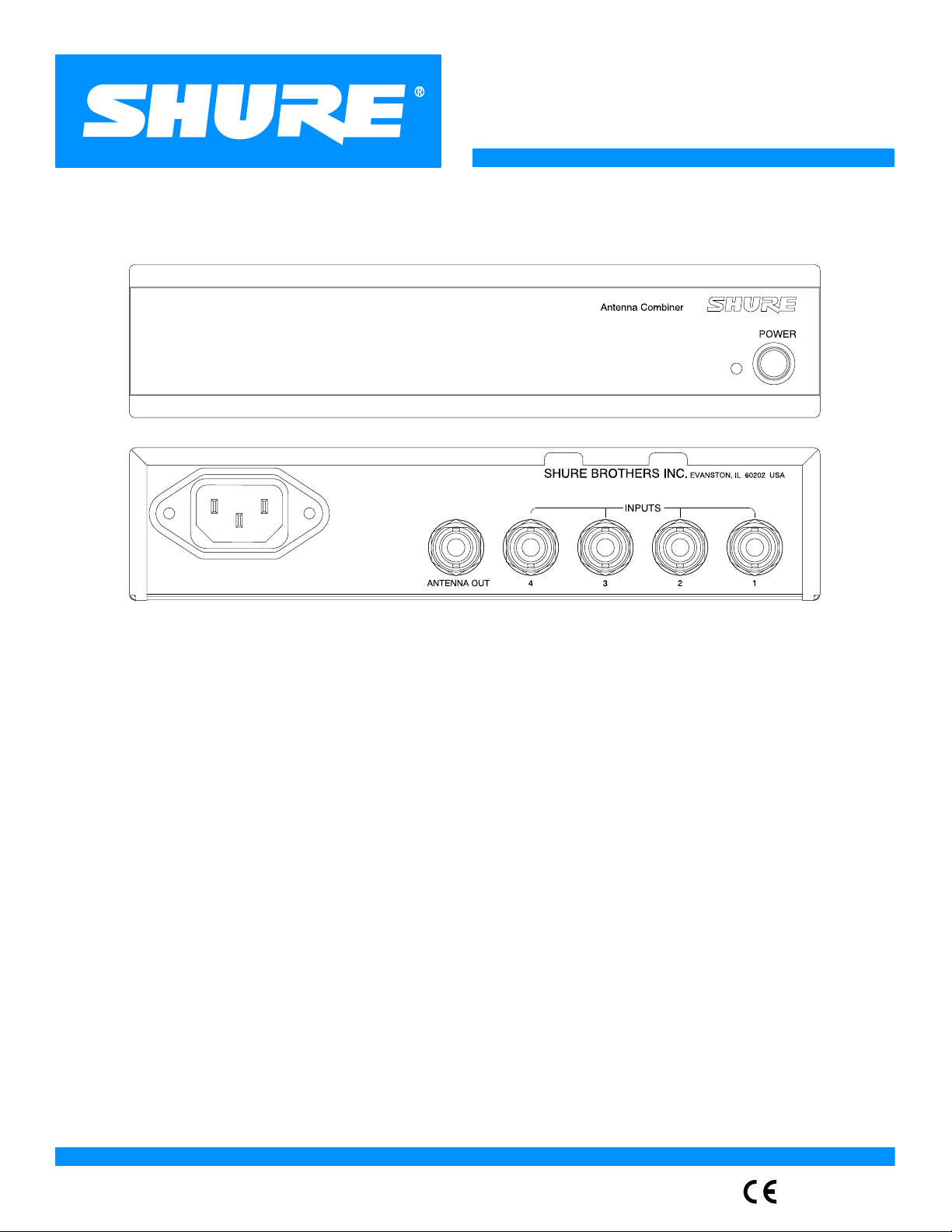
Wireless Antenna Combiner User Guide
Guide de l’utilisateur du répartiteur d’antenne sans fil
Bedienungsanleitung für die drahtlose Antennenweiche
Guía del usuario del combinador de antenas inalámbrico
Guida d’uso del combinatore di antenne senza fili
E1999, Shure Brothers Incorporated
27A8680 (SB)
Printed in U.S.A.
Page 2
TABLE OF CONTENTS
Introduction 2. . . . . . . . . . . . . . . . . . . . . . . . . . . . . . . . . . . . . . . . . . . . . . . . . . . . . . . . . . . . . . . . . . . . . . . . . . . . . . . . . . . .
Overview 2. . . . . . . . . . . . . . . . . . . . . . . . . . . . . . . . . . . . . . . . . . . . . . . . . . . . . . . . . . . . . . . . . . . . . . . . . . . . . . . . . . . . . .
Installation 3. . . . . . . . . . . . . . . . . . . . . . . . . . . . . . . . . . . . . . . . . . . . . . . . . . . . . . . . . . . . . . . . . . . . . . . . . . . . . . . . . . . . .
Appendix A. Specifications 4. . . . . . . . . . . . . . . . . . . . . . . . . . . . . . . . . . . . . . . . . . . . . . . . . . . . . . . . . . . . . . . . . . . . .
Appendix B. Rack Mounting Options 5. . . . . . . . . . . . . . . . . . . . . . . . . . . . . . . . . . . . . . . . . . . . . . . . . . . . . . . . . . . .
FCC Statement. The P7R Receiver complies with part 15 of the FCC rules. Operation is
subject to the following two conditions: (1) this device does not cause harmful interference,
and (2) this device must accept any interference received, including interference that may
cause undesired operation.
Licensing Statement. A user license may be required for operation. Contact the
communications authority in your country for more information.
Modifications to Approved Equipment. Changes or modifications not expressly
approved by Shure Brothers Incorporated could affect compliance with telecommunications
standards, thereby voiding the user’s authority to operate this product.
This symbol indicates that dangerous voltage constituting a risk of electric shock is present within this unit.
This symbol indicates that there are important operating and maintenance instructions in the literature accompanying
this unit.
English –
1
Page 3
INTRODUCTION
Shure PA-Series UHF Antenna Combiners are designed to allow up to four PSM
wireless transmitters to use a single antenna. The unit combines four PSM wireless
transmitters to a single antenna, reducing stage clutter and improving intermodulation
distortion performance.
Features
S
UHF operation.
S
Up to four wireless transmitters can be combined
into one transmitting antenna.
S
Low noise and intermodulation distortion. The PA
Antenna Combiner maintains clean signals with
minimal distortion.
S
Microstrip technology for signal combining and
filtering.
OVERVIEW
S
Four push/pull amplifiers for improved linear
performance.
S
Front-mounted antenna. The PA Antenna
Combiner comes with hardware to front-mount the
antenna, which allows for better radio
transmission.
S
Dual rackmount hardware. The PA Antenna
Combiner comes with hardware so that it can be
rackmounted with another PA Antenna Combiner
or PSM Transmitter into a single rack space.
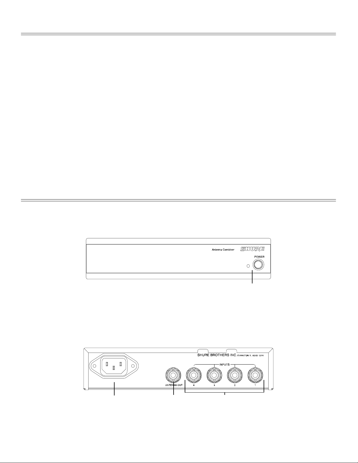
Front Panel
Ê Power Switch and LED. The green LED illuminates
when the power is on.
Rear Panel
Ê
ÊËÌ
Ê Power Connector.
Ë ANTENNA OUT Connector — 50 Ω, BNC.
English –
Ì INPUT Connectors — 50 Ω, BNC. For connecting
the unit to up to four wireless transmitters.
2
Page 4

INSTALLATION
Connection
1. Using the cables supplied with each PSM Transmitter, connect the ANTENNA OUT
of each PSM Transmitter to the INPUTS of the PA Antenna Combiner.
2. Attach the antenna (one supplied with each PSM Transmitter), or an optional
directional antenna such as the Shure Model PA705, to the ANTENNA OUT
connector of the PA Antenna Combiner.
3. Run the supplied power cable from the power connector to a power supply.
TO POWER
SUPPLY
TO POWER
SUPPLIES
TRANSMITTER 4
TRANSMITTER 3
TRANSMITTER 2
TRANSMITTER 1
English –
3
Page 5

APPENDIX A. SPECIFICATIONS
UHF Carrier Frequency Range
Certifications
Model Number Frequency Range
PA760 620 to 670 MHz
PA765 800 to 870 MHz
PA770 720 to 750 MHz
System Gain
0 dB (+2 dB, –4 dB)
Input/Output Port VSWR
Less than 1.7:1
Output Port Isolation
Greater than 23 dB
Third Ord er Intercep t Poin t (3 OIP)
Greater than 25 dBm
Input AC Line Voltage
100 to 240 Vac, 50/60 Hz (country dependent)
NOTE: This product is not completely disconnected from
the mains when the power switch is in OFF position.
Maximum Input Current
0.5 Aac
Maximum RF Input Power
+20 dBm (100 mW)
Impedance
50 Ω nominal
Operating Temperature Range
–7° C to +49° C
Overall Dimensions
44.5 mm high x 197.4 mm wide x 225.6 mm deep (1.75 in. x
7.770 in. x 8.880 in.)
Net Weight
1.34 Kg (2 lbs, 15.4 oz)
Input/Output Connector Type
BNC-type (4 input, 1 output)
PA760, PA770:
Certified by IC in Canada under RS 123. UL and cUL listed
to UL813 and CSA 22.2 No. 1.
P A760, PA765, PA770:
Voltage Directive (73/23/EEC) and EMC Directive
(89/336/EEC), eligible to bear CE marking. Meets Low
Voltage Requirements: VDE GS-Certified to IEC 60065.
Meets EMC Emission and Immunity Requirements: ETS
300 445.
Type accepted under FCC Part 74.
Conforms to European Union Low
Furnished Accessories
Rack Mount Kit PA745. . . . . . . . . . . . . . . . . . . . . . . . . . . . . .
2 ft. Coaxial Cable (RG-58/U) UA802. . . . . . . . . . . . . . . . . .
Optional Accessories
Unidirectional Antenna (620–870 MHz) PA705. . . . . . . . . .
2 ft. Coaxial Cable (RG-58/U) UA802. . . . . . . . . . . . . . . . . .
10 ft. Coaxial Cable (RG-58/U) PA725. . . . . . . . . . . . . . . .
25 ft. Coaxial Cable (RG-8/X) UA825. . . . . . . . . . . . . . . . . .
50 ft. Coaxial Cable (RG-8/X) UA850. . . . . . . . . . . . . . . . . .
Replacement Parts
Bulkhead Adapters 95A8647. . . . . . . . . . . . . . . . . . . . . . . . .
120 VAC Power Line Cord 95A8389. . . . . . . . . . . . . . . . . . .
230 VAC Power Line Cord 95A8247. . . . . . . . . . . . . . . . . . .
240 VAC Power Line Cord (U.K.) 95A8713. . . . . . . . . . . . .
English –
4
Page 6

APPENDIX B. RACK MOUNTING OPTIONS
Rack Mounting the PA Antenna Combiner
NOTE: Dual mounting with other Shure products. The PA Antenna
Combiner can also be dual mounted with a Shure SC or LX half-rack
wireless receiver. These same instructions apply, but the front panels will
not align evenly. The SC and LX receivers must use the SC and LX rack
ears. They cannot be mounted with PA Antenna Combiner rack ears.
However, the link bars are universal and can be used to connect the PA
Antenna Combiner with an LX or SC receiver.
WARNING: Do not torque the screws too tightly, or the chassis may be damaged.
Single Unit
1. Remove the screws and washers from each side of the unit.
2. Align the supplied rackmount brackets over the holes.
3. Using the screws and washers from step 1, fasten the rackmount brackets.
Dual-Mounted Units
1. Remove the screws and washers on each side of both units.
2. Placing the two units side-by-side, screw the link bars to the inside panels of each
unit. The units are designed so that the link bar on the right unit will fit directly on top
of the link bar of the left unit (facing front). Use two of the screws and washers from
step 1 per link bar to fasten the link bars.
3. Align the rackmount brackets on the outside panels of the units and fasten using four
of the screws and washers from step 1.
4. Place the two units next to each other so the link bars overlap and the screw holes
on the two align.
5. Fasten the link bars together using 4 supplied screws and washers.
NOTE: The link bars are designed with recesses in the side holes where the
screw head and washer fit in. Once the link bars are screwed on properly ,
the vertical holes will align. Each link bar has two threaded holes and two
unthreaded holes. In order to ensure proper fit, stack the link bars so that
the unthreaded holes on one bar align with the threaded holes on the other
bar. Then, each pair of screws fits in the opposite direction of the other pair ,
ensuring the stability of the link.
English –
5
Page 7

Mounting in an Equipment Rack
Ñ
ÑÑ
ÑÑÑ
ÑÑÑÑ
Ñ
Ñ
ÑÑÑÑÑ
Ñ
ÑÑ
ÑÑÑÑ
Ñ
Ñ
ÑÑÑÑ
ÑÑÑ
Ñ
Ñ
Ñ
Ñ
Ñ
Ñ
SINGLE MOUNT DUAL MOUNT
1. Insert the unit(s) into a 19-inch equipment rack.
2. Fasten the unit(s) to the rack using all four of the supplied screws.
Front Mounting the Antenna
The PA Antenna Combiner comes equipped so the antenna can be front-mounted.
Front-mounting prevents antenna cables from becoming entangled and greatly minimizes
RF interference from other cables. When a unit is located in a rack, antennas should be
either front- or remote-mounted.
1. Insert the bulkhead adapter through the hole of either mounting bracket, and secure
it from the front and the back using the supplied hardware.
2. Connect the supplied antenna cable to the combiner antenna output and bulkhead
adapter.
3. Install the antenna on the bulkhead adapter.
NOTE: The antenna which comes supplied with the PSM Transmitter can
be remote mounted. For remote mounted installations, however, we
recommend using the PA705 UHF Directional Antenna.
English –
6
 Loading...