

Page 1
Shure Brothers Incorporated
222 Hartrey Avenue
Evanston IL 60202-3696 U.S.A.
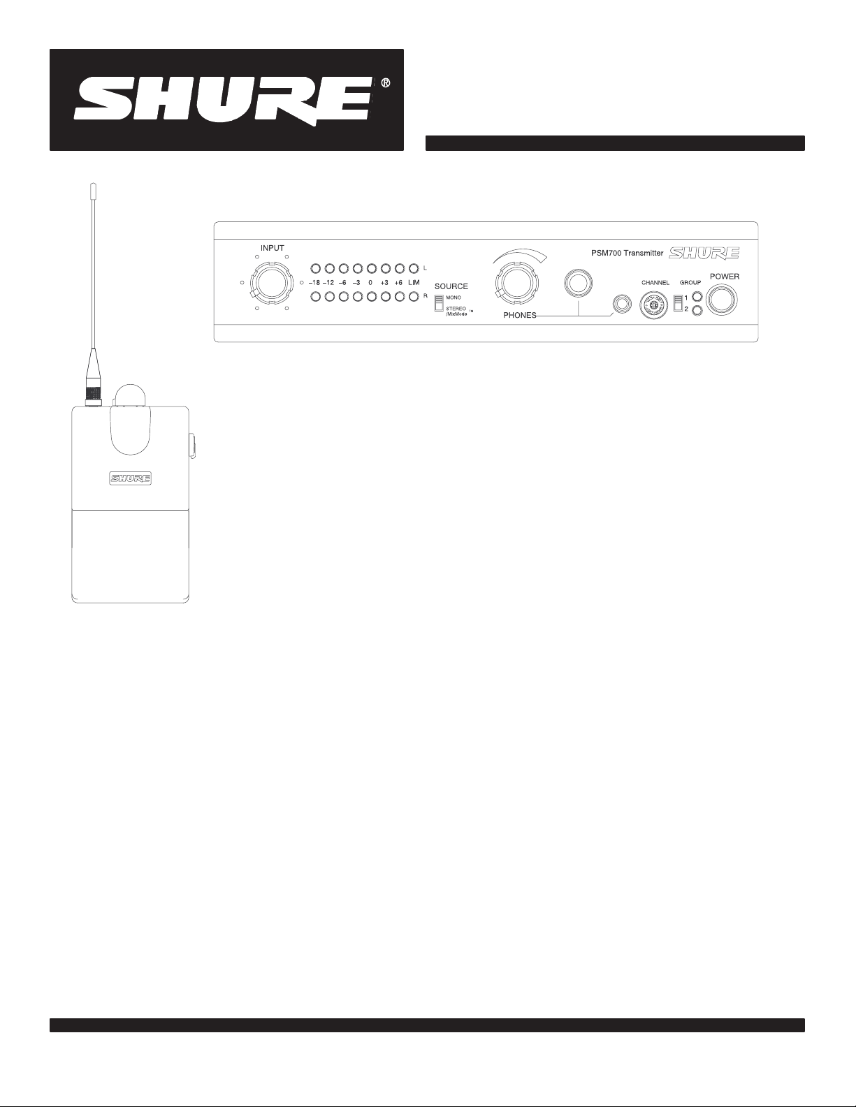
Shure PSM700
Personal Stereo Monitor System
R
PSM 700
Wireless Personal Stereo Monitor System
User Guide
Système de retour stéréo personnel sans fil
Guide de l’utilisateur
Drahtloses individuelles Stereomonitorsystem
Bedienungsanleitung
Sistema inalámbrico de monitor estereofónico personal
Guía del usuario
Sistema di controllo stereo personale senza fili
Guida d’uso
E1998, Shure Brothers Inc.
27A???? (QJ)
Printed in U.S.A.
Page 2
WARNING!
USING THIS SYSTEM AT EXCESSIVE VOLUMES CAN CAUSE PERMANENT HEARING DAMAGE.
USE AS LOW A VOLUME AS POSSIBLE.
In order to use this system safely , avoid prolonged listening at excessive sound pressure levels. Please use the following
guidelines established by the Occupational Safety Health Administration (OSHA) on maximum time exposure to sound
pressure levels before hearing damage occurs.
90 dB SPL at 8 hours
95 dB SPL at 4 hours
100 dB SPL at 2 hours
105 dB SPL at 1 hour
110 dB SPL at 1/2 hour
115 dB SPL at 15 minutes
120 dB SPL — avoid or damage may occur
It is difficult to measure the exact Sound Pressure Levels (SPL) present at the eardrum in live applications. In addition
to the volume setting on the PSM, the SPL in the ear is affected by ambient sound from floor wedges or other devices.
The isolation provided by the fit of quality earpieces is also an important factor in determining the SPL in the ear.
Here are some general tips to follow in the use of this product to protect your ears from damage:
1. Turn up the volume control only far enough to hear properly.
2. Ringing in the ears may indicate that the gain levels are too high. Try lowering the gain levels.
3. Have your ears checked by an audiologist on a regular basis. If you experience wax buildup in your ears, stop using
the system until an audiologist has examined your ears.
4. Wipe the ear molds with an antiseptic before and after use to avoid infections. Stop using the ear molds if they are
causing great discomfort or infection.
This symbol indicates that dangerous voltage constituting a risk of electric shock is present within this unit.
This symbol indicates that there are important operating and maintenance instructions in the literature accompanying
this unit.
FCC Statement. The P7R Receiver complies with part 15 of the FCC rules. Operation is
subject to the condition that this device does not cause harmful interference.
Licensing Statement. Changes or modifications not expressly approved by Shure
Brothers Inc. could void your authority to operate the equipment. Licensing of Shure wireless
equipment is the user ’s responsibility, and licensability depends on the user ’s classification
and application. Shure strongly urges the user to contact the appropriate authority concerning
proper licensing.
English –
1
Page 3

TABLE OF CONTENTS
Getting Started with the PSM700 3. . . . . . . . . . . . . . . . . . . . . . . . . . . . . . . . . . . . . . . . . . . . . . . . . . . . . . . . . . . . . . . . .
Introduction 4. . . . . . . . . . . . . . . . . . . . . . . . . . . . . . . . . . . . . . . . . . . . . . . . . . . . . . . . . . . . . . . . . . . . . . . . . . . . . . . . . . . . .
Description 4. . . . . . . . . . . . . . . . . . . . . . . . . . . . . . . . . . . . . . . . . . . . . . . . . . . . . . . . . . . . . . . . . . . . . . . . . . . . . . . . . .
Components 4. . . . . . . . . . . . . . . . . . . . . . . . . . . . . . . . . . . . . . . . . . . . . . . . . . . . . . . . . . . . . . . . . . . . . . . . . . . .
Features 4. . . . . . . . . . . . . . . . . . . . . . . . . . . . . . . . . . . . . . . . . . . . . . . . . . . . . . . . . . . . . . . . . . . . . . . . . . . . . . .
Overview 5. . . . . . . . . . . . . . . . . . . . . . . . . . . . . . . . . . . . . . . . . . . . . . . . . . . . . . . . . . . . . . . . . . . . . . . . . . . . . . . . . . . . . . .
P7T Transmitter 5. . . . . . . . . . . . . . . . . . . . . . . . . . . . . . . . . . . . . . . . . . . . . . . . . . . . . . . . . . . . . . . . . . . . . . . . . . . . . .
Front Panel 5. . . . . . . . . . . . . . . . . . . . . . . . . . . . . . . . . . . . . . . . . . . . . . . . . . . . . . . . . . . . . . . . . . . . . . . . . . . . .
Back Panel 5. . . . . . . . . . . . . . . . . . . . . . . . . . . . . . . . . . . . . . . . . . . . . . . . . . . . . . . . . . . . . . . . . . . . . . . . . . . . .
P7R Receiver 6. . . . . . . . . . . . . . . . . . . . . . . . . . . . . . . . . . . . . . . . . . . . . . . . . . . . . . . . . . . . . . . . . . . . . . . . . . . . . . . .
Controls and Connectors 6. . . . . . . . . . . . . . . . . . . . . . . . . . . . . . . . . . . . . . . . . . . . . . . . . . . . . . . . . . . . . . . . .
DIP Switches 6. . . . . . . . . . . . . . . . . . . . . . . . . . . . . . . . . . . . . . . . . . . . . . . . . . . . . . . . . . . . . . . . . . . . . . . . . . .
Installation and Applications 7. . . . . . . . . . . . . . . . . . . . . . . . . . . . . . . . . . . . . . . . . . . . . . . . . . . . . . . . . . . . . . . . . . . . .
Operating Modes 7. . . . . . . . . . . . . . . . . . . . . . . . . . . . . . . . . . . . . . . . . . . . . . . . . . . . . . . . . . . . . . . . . . . . . . . . . . . . .
Stereo Control 7. . . . . . . . . . . . . . . . . . . . . . . . . . . . . . . . . . . . . . . . . . . . . . . . . . . . . . . . . . . . . . . . . . . . . . . . . .
MixMode Control 8. . . . . . . . . . . . . . . . . . . . . . . . . . . . . . . . . . . . . . . . . . . . . . . . . . . . . . . . . . . . . . . . . . . . . . .
Mono Control 8. . . . . . . . . . . . . . . . . . . . . . . . . . . . . . . . . . . . . . . . . . . . . . . . . . . . . . . . . . . . . . . . . . . . . . . . . . .
Monitoring the Performers’ Mixes 8. . . . . . . . . . . . . . . . . . . . . . . . . . . . . . . . . . . . . . . . . . . . . . . . . . . . . . . . . .
Loop Applications 9. . . . . . . . . . . . . . . . . . . . . . . . . . . . . . . . . . . . . . . . . . . . . . . . . . . . . . . . . . . . . . . . . . . . . . . . . . . .
Running Multiple PSM700 Wireless Systems under Stereo Control 9. . . . . . . . . . . . . . . . . . . . . . . . . . . .
Running Floor Monitors through a P7T Transmitter 9. . . . . . . . . . . . . . . . . . . . . . . . . . . . . . . . . . . . . . . . . .
Running Multiple PSM700 Systems under MixMode Control 10. . . . . . . . . . . . . . . . . . . . . . . . . . . . . . . . .
Running a Recording Device through a P7T Transmitter 10. . . . . . . . . . . . . . . . . . . . . . . . . . . . . . . . . . . . .
Accessories 11. . . . . . . . . . . . . . . . . . . . . . . . . . . . . . . . . . . . . . . . . . . . . . . . . . . . . . . . . . . . . . . . . . . . . . . . . . . . . . . .
Troubleshooting 12. . . . . . . . . . . . . . . . . . . . . . . . . . . . . . . . . . . . . . . . . . . . . . . . . . . . . . . . . . . . . . . . . . . . . . . . . . . . . . . .
Appendix A. Specifications 12. . . . . . . . . . . . . . . . . . . . . . . . . . . . . . . . . . . . . . . . . . . . . . . . . . . . . . . . . . . . . . . . . . . . .
Custom Earpieces 14. . . . . . . . . . . . . . . . . . . . . . . . . . . . . . . . . . . . . . . . . . . . . . . . . . . . . . . . . . . . . . . . . . . . . . . . . . .
Voltage Selection 14. . . . . . . . . . . . . . . . . . . . . . . . . . . . . . . . . . . . . . . . . . . . . . . . . . . . . . . . . . . . . . . . . . . . . . . . . . . .
Appendix B. Rack Mounting Options 15. . . . . . . . . . . . . . . . . . . . . . . . . . . . . . . . . . . . . . . . . . . . . . . . . . . . . . . . . . . .
Rack Mounting the P7T Transmitter 15. . . . . . . . . . . . . . . . . . . . . . . . . . . . . . . . . . . . . . . . . . . . . . . . . . . . . . . . . . . .
Front Mounting the Antenna 16. . . . . . . . . . . . . . . . . . . . . . . . . . . . . . . . . . . . . . . . . . . . . . . . . . . . . . . . . . . . . . . . . .
English –
2
Page 4
GETTING STARTED WITH THE PSM700 SYSTEM
Thank you for purchasing the PSM700 Personal Stereo Monitor System. The PSM700
is a revolutionary new product family designed to meet the diverse audio monitoring needs of
musicians, engineers, and stage performers.
The following are step-by-step instructions showing how to connect your PSM700
wireless system to an audio source while introducing you to some of its features.
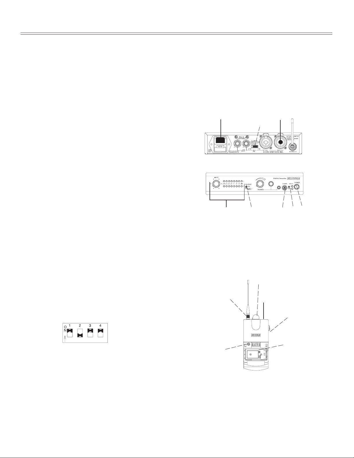
P7T Transmitter Setup
1. Plug the power cord to the power connector.
Connect the other end to a power supply.
2. Attach the antenna to the
ANTENNA OUT BNC connector.
1. 2.
4.
3. Plug the cable(s) from the audio source (mixer,
audio output, CD player) into the LEFT/RIGHT
audio inputs. For a stereo send, use both inputs.
For mono send, use either the LEFT or RIGHT input.
NOTE: All inputs are phantom power
protected up to 60 VDC.
4. Put the PAD switch in the +4 dB position if the
input signal is +4 dB, or the –10 dB position if
the input signal is –10 dB.
5. Turn on the P7T Transmitter.
6. Set the SOURCE switch to match the
audio send (stereo/mono).
7. Set the GROUP switch in the UP position
9.
to frequency GROUP #1.
8. Set the CHANNEL dial to the desired frequency.
IMPORTANT: Never set more than ONE transmitter to the same operating
frequency .
9. Power on the audio source and adjust the level control so the LEDs are in the –3 dB
to +3 dB range.
3.
5.6. 7.8.
P7R Receiver Setup
10. Attach the bodypack antenna to the ANTENNA
connector by aligning the red dot and threading the
shell until it is tight.
11. Open the battery door and insert a 9V alkaline battery.
12. Set the DIP switches according to the illustration.
13. Set the frequency dial to the desired frequency.
14. Set the balance control to the center detent position.
15. Insert the plug of the earpieces into the headphone
connector on the top panel.
16. Insert the earpieces into your ears.
17. Turn on the receiver by rotating the volume knob clockwise past the click, then slowly
raise the volume to a comfortable listening level.
Now you know the basic setup for your new PSM700 Personal Stereo Monitor System. If
any troubles occur , please refer to the
manual goes into greater detail on features and applications — including MixModet control,
which enables you to customize your own mixes. Please read the rest of the manual to help
you make the most of your PSM700 System.
#1: UP – Group #1
#2: DOWN – Stereo control
#3: UP – High frequency boost
#4: UP – Limiter on
T roubleshooting
English –
3
17.
10.
15.
14.
0
4
C
8
11. & 12.
13.
section of this manual. The rest of the
Page 5
INTRODUCTION
Description
The Shure PSM700 Personal Stereo Monitor System is a frequency-agile, UHF
wireless, two-channel stereo, monitor system designed for onstage applications. The PSM
has several advantages over onstage loudspeaker monitors: it is less visible, has better
sound, allows freedom of movement, and reduces the chances of feedback. It is a versatile
system, designed for use in many different sound reinforcement applications: public
address, live music, theater, and electronic news gathering (ENG). The wireless system is
frequency compatible with other Shure UHF and VHF wireless systems.
Components
P7T WIRELESS TRANSMITTER
E-SERIES EARPIECE
PA715 ANTENNA
P7R WIRELESS RECEIVER
P7T Wireless T ransmitter with rack-mounting hardware and one antenna
P7R Wireless Body-Pack Receiver with antenna
One E1 or E5 Earpiece with foam ear inserts
Features
S
UHF operation.
S
Stereo or MixModet control for custom monitor
mixes.
S
32 user-selectable frequencies per system.
S
Up to 16 compatible frequencies for 16 separate
mixes.
S
Frequency compatible with all Shure Wireless
systems (country dependent).
S
MPX Stereo audio transmission.
S
Switchable high-frequency boost on P7R.
S
+4 dBu/–10 dBV input level select switch on P7T.
S
Electronically balanced, combined 1/4-in./XLR
connectors on P7T can be used with balanced or
unbalanced connections.
S
Volume and Balance dials on the P7R Receiver for
easy user access.
S
Internal linear power supply on P7T, switchable
between 120 VAC and 230 VAC.
S
Peak transmitter modulation limiter with fixed
threshold and modulation limit indicators.
S
Loop out connectors on P7T for multiple mix
setups and easy installation.
S
Tone-Key squelch.
S
Half-rack chassis on P7T complete with mounting
hardware.
S
All metal construction on P7T and P7R
S
Headphone monitor on P7T for local listening.
English –
4
Page 6
OVERVIEW
P7T Transmitter
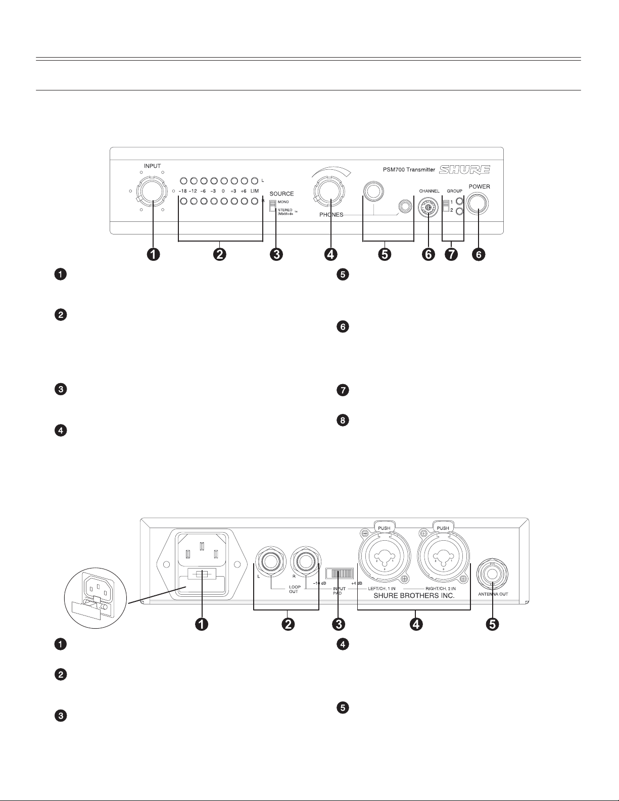
Front Panel
INPUT Control. This controls the signal level to the
transmitter modulator. For optimum sound, the input
level should be set in the –3 dB to +3 dB range.
Stereo INPUT Meters. Each channel has an eight
LED meter which indicates the modulation level of
the radio signal. Important: When the LIM (limit)
LEDs illuminate, the system is overdriven. Reduce
the input knob to keep the input level LEDs at around
–3 dB to +3 dB.
SOURCE Switch. Set to MONO when only one
input is needed. Set to STEREO/MixMode when
both inputs are needed.
PHONES V olume Control. This controls the signal
level to the headphone output. This does not affect
the input level.
Rear Panel
Headphone Connectors — 1/4-in. phone and 3.5
mm (1/8-in) mini. Each connector is configured as
left=tip, right=ring, ground=sleeve. Please note that
only one of these outputs can be used at a time.
CHANNEL Select Control. This dial determines
the frequency which the P7T transmits. There are
two groups of sixteen frequencies available,
corresponding with those on the P7R receiver. To
change the frequency , use the supplied screwdriver.
GROUP Switch. This selects the channel group, 1
or 2.
Power Switch. Press this button to turn the unit on.
Power Connector and Fuse. Connects to a power
supply. The fuse is located in the bottom drawer.
LOOP OUT Connectors — 1/4-in. phone,
balanced. Additional connectors internally wired to
the respective LEFT/RIGHT input connectors.
INPUT PAD Switch. Selects the input signal level
for –10 dBV or +4 dBu operation. See the
specifications for the audio equipment to be
connected for the proper signal level.
English –
LEFT/CH. 1 and RIGHT/CH. 2 Input Connectors
— Combined 1/4-in. phone and XLR (female),
balanced. Electronically balanced inputs can be
used with either balanced or unbalanced outputs.
Either connector can be used for mono control.
Antenna Connector — 50 Ω, BNC type. This
connects to the antenna to transmit UHF signals to
the receiver.
5
Page 7

P7R Receiver
Controls and Connectors
Balance Control. In stereo mixes, this controls the
left/right balance. In MixModet, this controls the
mix level of two transmitter inputs.
Headphone Connector. 3.5 mm (1/8-in.) phone
jack connects to the E1 earpieces. Left=tip,
right=ring, ground=sleeve.
LOW BATT Indicator. This LED illuminates red
when the battery has approximately 45 minutes of
operating time remaining, depending on the volume.
Power LED. This green LED illuminates when the
power is ON and the battery is good.
ON/OFF and Volume Control. Full
counter-clockwise turns the P7R OFF. Turn the dial
clockwise past the click to turn the P7R ON. Once
ON, turn the dial clockwise to raise the volume, and
counter-clockwise to lower the volume in the
earpieces.
Antenna and Connector. An easily removable
antenna connects to the P7R to receive RF signals
from the P7T Transmitter.
RF LED. Illuminates when the P7R is receiving a
signal from the transmitter.
Battery Compartment. Accepts one 9-volt battery
(Duracell recommended). Open the door by
pressing the latches on both sides and pulling.
DIP Switches. Using the DIP Switches, you can
customize the operation of the receiver. See
Switches
CHANNEL Select Control. This dial determines
the frequency which the P7R receives. There are
two groups of sixteen frequencies available,
corresponding with those on the P7T transmitter. To
change the frequency , use the supplied screwdriver.
Use DIP switch 1 to select the frequency group.
Belt Clip.
.
DIP
English –
6
Page 8

DIP Switches
DIP
FUNCTION UP DOWN
SWITCH
1 GROUP Select Frequency Channel Group 1 Frequency Channel Group 2
2 Stereo/MixMode Select MixMode control stereo control
3 Equalization (Flat/High Boost) Gives a 6 dB boost at 10 kHz
4 Limiter defeat Limiter on Limiter off
IMPORTANT: The Limiter is designed to respond to and limit the loudness of unexpectedly
high signals. It is not designed to prevent long term exposure to high SPL levels.
designed for use with the E-Series earpieces, so the maximum limited SPL may be
different with other earpieces.
provided with this system. However, a limiter defeat switch has been provided for those who
would prefer to use an external limiter product.
Selecting Frequencies
The Shure PSM700 Personal Stereo Monitor System is frequency-agile, with two
groups of 16 channels for a total of 32 different possibe operating frequencies. The P7T
transmitter and the P7R receiver each has a switch for selecting between the two groups,
and a rotary dial for selecting the channel. Use the supplied screwdriver for adjusting the
rotary dial.
normal response
for a better high-end response
It is
We recommend that you always use the built-in limiter
GROUPCHANNEL
4
8
0
C
1
2
0
4
C
8
1. Set the GROUP switch on the P7T transmitter to the desired group (group 1 or 2).
Set DIP switch 1 on the P7R receiver to the same group.
2. Set the CHANNEL select control on the P7T transmitter to the desired frequency
channel. Set the CHANNEL select control on the P7R receiver to the same
frequency channel.
English –
7
Page 9
INSTALLATION AND APPLICATIONS
Ñ
The flexible design of the PSM700 Personal Stereo Monitor System makes configuring a
monitor mix very simple. In addition, the unique MixMode circuitry enables you to customize
your own individual mix in a multiple mix environment. To help you install the PSM700 into
your sound system, the tables and diagrams in this section describe three distinct modes of
operating the system. Although the examples show only single system setups, you can
configure multiple wireless systems in a setup. Some multiple mix setups are detailed in the
LOOP Applications
Operating Modes
For optimum performance, The P7T requires a LINE level input signal.
Stereo Control Used for conventional Stereo monitor mixes.
MixMode Control Used for creating an individual mix between two distinct moni-
Mono Control Used when only one (mono) monitor mix is available.
section of this chapter.
Transmitter
Receiver
Balance Dial
tor sends.
Transmitter
Receiver
Balance Dial
Transmitter
Receiver
Balance Dial
Stereo/MixMode setting
Stereo setting
Varies stereo left/right image
Stereo/MixMode setting
MixMode setting
Varies levels between mixes
Mono setting
Stereo setting
Varies the right/left volume control
NOTE:
For the best results, the input signal must be a LINE level signal.
consistency throughout the following diagrams, a mixing console is shown as the source
supplying the audio signal to the P7T transmitter. However, any balanced or unbalanced
send that outputs a LINE level should drive the P7T . Some devices that would work are CD
players, DAT machines, direct injection boxes, and microphone preamplifiers.
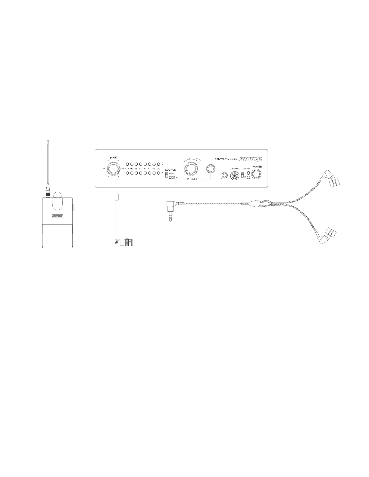
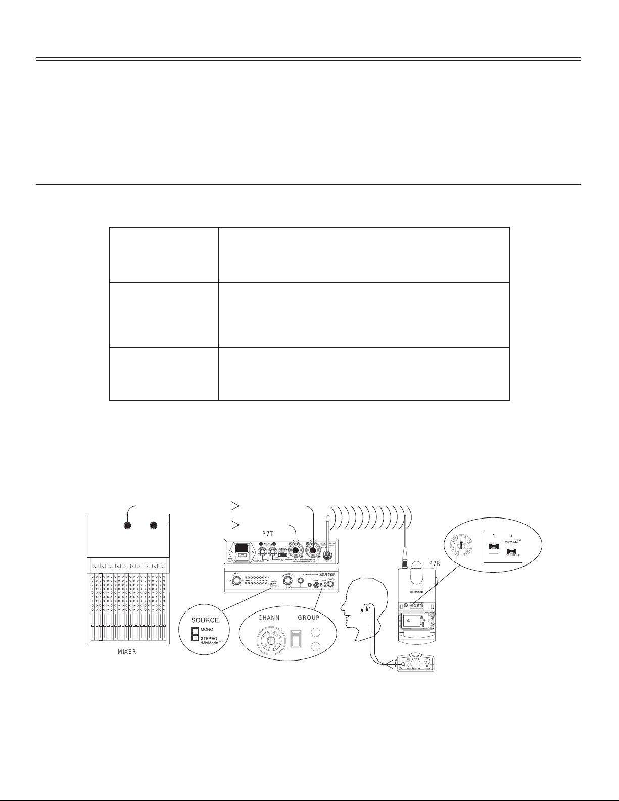
Stereo Control
This diagram shows how to connect the PSM700 system with a stereo monitor mix.
MIXER
1. Connect the stereo mixer outputs to the L/CH1. and R/CH2. INPUTs on the P7T
transmitter
2. Set the SOURCE switch on the P7T front panel to STEREO.
3. Set DIP switch 2 of the P7R Receiver to STEREO.
4. Set the P7T transmitter and the P7R receiver to the same frequency.
5. Use the balance control on the P7R Receiver to adjust the balance of the Right and
Left channel volume.
P7T
0
For
0
GROUP 1
4
C
8
P7R
0
4
C
8
GROUPCHANNEL
4
C
1
8
2
GROUP 2
English –
8
Page 10

MixMode Control
This diagram shows how to connect the PSM700 system with two monitor mixes
combined at the receiver. This allows you to vary the level between the two mixes to create a
custom mix.
VOICE MIX
BAND MIX
P7T
FULL LEFT
BAND MIX LOUDER
P7R
0
4
C
8
CH. 2CH. 1 CH. 2CH. 1
FULL RIGHT
VOICE MIX LOUDER
MIXER
1. Connect the monitor mix 1 and monitor mix 2 mixer outputs of the mixer to the L/CH.
1 and R/CH. 2 audio inputs of the P7T transmitter.
2. Set the SOURCE switch on the P7T transmitter to STEREO.
3. Set DIP switch 2 on the P7R receiver to MixModet.
4. Set the P7T transmitter and the P7R receiver to the same frequency.
5. Use the balance control on the P7R to adjust the relative levels between the two
monitor mixes.
Mono Control
This diagram shows how to connect the PSM700 system with a mono monitor mix.
GROUPCHANNEL
4
0
C
1
8
2
P7T
0
4
C
8
P7R
0
GROUP 1
4
C
8
GROUP 2
0
GROUP 1
4
C
8
GROUP 2
4
8
MIXER
0
C
1. Connect the mono monitor output of the mixer to either the Left or Right audio inputs
of the P7T.
2. Set the SOURCE switch on the front panel to MONO.
3. Set DIP switch 2 of the P7R to STEREO.
4. Set the P7T transmitter and the P7R receiver to the same frequency.
Monitoring the Performers’ Mixes
With the frequency select controls, you can soundcheck the different mixes in a multiple
transmitter setup. Using one P7R receiver, set that P7R to same frequency as each successive
P7T to make sure the you hear the transmission. If necssary, twist the balance dial to check for
proper left/right stereo balance or MixMode operation.
GROUPCHANNEL
1
2
English –
9
Page 11

LOOP Applications
The LOOP OUT L (left) and R (right) outputs allow the signal going through the P7T to be
run to other devices. The LOOP feature of the P7T can be used for any number of
applications. Shown here are only a few examples of how it can be used.
NOTE: The LOOP connectors act as either inputs or outputs. They can be
used as outputs when the LEFT and RIGHT INPUT connectors are used for
input. However, LOOP connectors can also act as inputs when connected
directly to the outputs of a mixer. When the LOOP connectors are used as
inputs, the LEFT and RIGHT INPUT connectors act as outputs. These
diagrams show the LOOP connectors being used as outputs. Also, the
input pad does not affect the level of the LOOP signals.
Running Multiple PSM Wireless Systems Under Stereo Control
The LOOP OUT connectors can be used to send the same monitor stereo signals to
multiple P7T wireless transmitters. This will free up busses on the mixing console, allowing
you more freedom with your audio system. Simply connect a P7T to the mixing console as
described in
Stereo Control
unit to the LEFT/RIGHT Input connectors of the next unit. Connect subsequent unit in the
same way.
, then run 1/4-in to 1/4-in from the L/R LOOP connectors of the first
P7T #1
P7T #2
MIXER
P7T #3
P7R #2
P7R #3
Running Floor Monitors Through a P7T Transmitter
The monitor audio signal can be sent through the LOOP connectors to another amplifier,
such as an amplifier for an onstage monitor system. When setup this way , the P7R and the
onstage monitors will have the same audio.
P7T
P7R #1
MIXER
FLOOR MONITOR
AMPLIFIER
English –
P7R
10
Page 12

Running Multiple PSM Wireless Systems Under MixMode Control
Ñ
Ñ
A main mono monitor mix can be sent to multiple P7T transmitters, then independent
monitor mixes can be sent to the second channel of each. This will allow an entire band to
hear the same monitor mix, while giving each individual player a separate mix of their own.
Each player can then use the balance control to adjust the levels between their own mix and
the main mono monitor mix.
BAND MIX/
SOLO MIX 1
SOLO MIX 3
SOLO MIX 2
SOLO MIX 1
MIXER
BAND MIX/
SOLO MIX 2
BAND MIX
SOLO MIX 1
SOLO MIX 2
SOLO MIX 3
P7T #1
P7T #3
BAND MIX/
SOLO MIX 3
BAND MIX
P7T #2
P7R #1
BAND MIX
P7R #2
P7R #3
Running a Recording Device Through a P7T Transmitter
If you would like to make a recording of a performance, the LOOP outputs can be
connected to the inputs of a tape deck, DAT, or other recording device.
AUX 1
OUT
MIXER
AUX 2
OUT
P7T
CASSETTE RECORDER
English –
11
P7R
Page 13

TROUBLESHOOTING
PROBLEM
No sound at the Receiver n Check the power cord on the Transmitter and make
Low Receiver Range n Make sure all antennas are fully inserted and se-
Receiver sounds fuzzy or
distorted
Low audio output at the
receiver headphones
SOLUTION
sure it is powered on.
n Make sure both the transmitter and the receiver are
set to the same frequency.
n Make sure the earpiece is plugged in to the receiver.
n Make sure receiver is on and the battery is good.
n Make sure both antennas are correctly attached.
n Listen to the headphone monitor on the transmitter
to check audio feed.
cured on to jacks.
n Try to maintain line-of-sight between transmitter and
receiver.
n Try the other frequencies in case interference is limit-
ing the range.
n Check for television channel interference.
n Make sure the PA715 antenna is not remote
mounted.
n Make sure no other transmitters are operating on
your frequency.
n Make sure transmitter input level is 0 dB ±3 dB for
optimum performance.
n Listen to the headphone monitor on the transmitter
to check audio feed.
n Try and maintain a minimum of 10 ft. between trans-
mitter antennas and receiver when using multiple
transmitters.
n Make sure transmitter input level is 0 dB ±3 dB for
optimum performance.
n Switch the transmitter pad to –10 dBV position if the
input is too low.
English –
12
Page 14

APPENDIX A. TECHNICAL SPECIFICATIONS
SYSTEM
rf Carrier Frequency Range
722 to 862 MHz (country dependent)
Operating Range
300 ft. (environment dependent)
Audio Frequency Response
50 to 15k Hz (+0, –3 dB re 1KHz); earpiece dependent
Image Rejection
???????? dB typical
Spurious Rejection
60 dB typical
Total Harmonic Distortion
0.8% typical (Ref. ±35 KHz deviation)
Modulation
FM ±35 kHz Deviation (Nominal), MPX Stereo
Channel Separation
35 dB typical
Signal-to-Noise Ratio
????????? dB typical (A-weighted)
Operating Temperature
–7° C to +49° C (+20° F to 120° F)
Battery Life
4–6 hours, volume dependent
Polarity
P7T audio inputs to P7R audio outputs: Non-inverting
XLR: pin 2 positive with respect to pin 3
1/4-in. TRS: Tip positive with respect to ring
P7T TRANSMITTER
RF Output Power
100 mW (+20 dBm) typical conducted (country
dependent)
Modulation Limiter
Internal peak limiter (>10:1 compression)
Antenna
External whip, 50 Ω BNC connector
Power Requirements
P7T: 120 Vac, 50/60 Hz
EP7T: 230 Vac, 50/60 Hz
NOTE: This product is not disconnected from the mains
power supply when the power switch is in the OFF
position.
Current
115 mAac maximum at 120 Vac
55 mAac maximum at 230 Vac
Fuse
P7T: 120 Vac, 160 mA/250 V (SLO-BLOR)
EP7T: 230 Vac, 80 mA/250 V time delay
FUSE
Dimensions
44.5 mm X 197.4 mm X 238.1 mm (1 3/4 in. X 7 3/4 in. X 9
1
/2 in.)
Net Weight
3.30 kg (3 lbs., 4.8 oz.)
P7R RECEIVER
rf Sensitivity
1.2 µV typical
Squelch Threshold
4 µV typical
Antenna Input Impedance
50 Ω typical
Antenna
External, threaded connector
Power Requirements
9 V battery
Audio Output Connector
3.5 mm Stereo (Left = tip, Right = ring, Ground = sleeve)
Minimum Load Impedance
16 Ω
Net Weight
0.52 lbs.
Overall Dimensions
27.18 mm X 64.52 mm X 85.09 mm
(1.070 in. X 2.540 in. X 3.350 in.)
Certification
P7T: Type Accepted under FCC Parts 74 and 90.
Certified by IC in Canada under TRC–78. UL and cUL
Listed.
EP7T: Conforms to European Union Directives, eligible to
bear CE marking. Type Certifiedto BZT 17 TR 2019, and
BAPT 122 R 1. EMC Immunity Certified to ETS 300 445.
VDE GS Certified to EN 60 065
P7R: Approved under the Notification provision of FCC Part
15. Certified by IC in Canada under TRC-78. Conforms to
European Union Directives, eligible to bear CE marking.
Type Certified to BZT 17 TR 2019, and BAPT 122 R 1. EMC
Immunity Certified to ETS 300 445.
FURNISHED ACCESSORIES
Body-Pack Antenna P A710. . . . . . . . . . . . . . . . . . . . . . . . .
Transmitter Antenna PA715. . . . . . . . . . . . . . . . . . . . . . . . .
Rack Mount Kit PA745. . . . . . . . . . . . . . . . . . . . . . . . . . . . .
Bag of 10 Foam Ear Inserts PA750. . . . . . . . . . . . . . . . . . .
60 cm (2 ft) Coaxial Cable (RG-58/U) UA802. . . . . . . . . .
OPTIONAL ACCESSORIES
Antenna Combiner PA770 (120 V AC). . . . . . . . . . . . . . . .
Unidirectional Antenna PA705. . . . . . . . . . . . . . . . . . . . . . .
10 ft Coaxial Antenna Cable (BNC connector) PA725. . .
Triple-Flange Ear Inserts (2) PA755. . . . . . . . . . . . . . . . . .
PA765E (240 VAC)
English –
13
Page 15

Connectors
P7T Audio Inputs (LEFT/CH.1 and RIGHT/CH.2)
Connector:
(XLR and
1/4-inch
combined)
Configuration: electronically
Actual
Impedance:
Nominal
Input Level:
Maximum
Input Level:
Pin
Assignments:
Phantom Power
Protection?
XLR (female)
balanced
20 kΩ 20 kΩ
+4 dBu
(+4 input level)
–10 dBV
(–10 input level)
+25 d Bu
(+4 input level)
+13 d Bu
(–10 input level)
Pin 1 = ground
Pin 2 = h ot
Pin 3 = cold
Yes
Up to 60 VDC
1
/4-inch
phone jack
(female)
electronically
balanced
+4 dBu
(+4 input level)
–10 dBV
(–10 input level)
+25 d Bu
(+4 input level)
+13 d Bu
(–10 input level)
Tip = hot
ring = cold
sleeve = ground
Yes
Up to 60 VDC
P7T L/R LOOP Outputs (IN and OUT)
(XLR and 1/4-inch combined)
Connector:
Configuration: electronically
Actual
Impedance:
Nominal
Input Level:
Maximum
Input Level:
Pin
Assignments:
Phantom Power
Protection?
(+4 input level)
(–10 input level)
(+4 input level)
(–10 input level)
sleeve = ground
Up to 60 VDC
1
/4-inch
jack (female)
balanced
20 kΩ
+4 dBu
–10 dBV
+25 d Bu
+13 d Bu
Tip = hot
ring = cold
Yes
Voltage Selection
P7T and EP7T transmitters can be internally modified to
operate at either 120 Vac or 230 Vac.
WARNING
Voltages in this equipment are hazardous to life.
No user-serviceable parts inside. Refer all
servicing to qualified service personnel.
The safety certifications of the P7T do not apply
when the operating voltage is changed from the
factory setting.
To change the operating voltage, follow these steps.
1. Disconnect the P7T from the ac power source.
2. Remove the eight Phillips head screws securing the top
cover.
3. Locate Voltage Selector switch SW4 adjacent to power
transformer T1 and, using a screwdriver, turn the center
rotor to the desired position:
For 120 V operation,
For 230 V operation,
4. Locate fuse and remove it. Replace it with the proper fuse:
For 120 V operation,
For 230 V operation,
turn it to the 115 V position.
turn it to the 230 V position.
use a 160 mA, 250 V , slow-blow fuse.
use a 80 mA, 250 V , time delay fuse.
Fuse part numbers are:
Fuse T ype
80 mA, 250 V
time delay
160 mA, 250 V
SLO-BLO
Shure Part No. Part No.
80H380 Schurter
.034.3106
80K258 Littelfuse
218.160
R
5. Replace the power cord with the proper power cord:
For 120 V operation,
use an IEC appliance connector on
the equipment end and a mains connector suitable for 1 15
V operation on the other.* (Shure part #95A8389.)
For 230 V operation,
use an IEC appliance connector on
the equipment end and a CEE 7/7 (“Schuko”) mains
connector on the other.* (Shure part #95A8247.)
*For systems requiring other mains connectors, obtain a power cord with an
IEC 320 type mating connector for connection to the P7T , and an appropriate
plug on the other end for connection to the mains. The supplied cord uses
Harmonized IEC Cordage with color coding as follows: Brown = Line, Blue =
Neutral, Green/Yellow = Ground.
English –
14
 Loading...