

Page 1
UC Wireless Systems
The flexibility and performance of professional-quality UHF
wireless, specifically designed for houses of worship, trade shows,
schools, businesses and club installations. Available at a moderate
price, UC systems can be configured with handheld, lavalier, head-
SYSTEM FEATURES
• UHF Band Operation. The Shure UC System operates within
the UHF frequency band, which is less congested than the
VHF band. Typically, UHF systems encounter less interference
than VHF systems.
• Frequency Agility. The UC transmitter and receiver frequen-
cies can be changed to avoid RF interference. This ensures
interference–free operation, even in the most congested RF
environments.
• 1/2 Rack Receiver Design. The UC4 receiver interfaces with
the HR (half–rack) format to save rack space. The UC4 receiver is supplied with hardware for single and dual rack mounting.
• MARCAD Diversity. Exclusive Shure MARCAD (MAximum
Ratio Combining Audio Diversity) circuitry monitors signals
from both receiver sections and combines them into a single
output signal. MARCAD provides superior reception and exceptional freedom from dropouts.
• Built–in Equalizer (On Receiver). Lets you tailor frequency
response to match other devices in the system.
• T one Key Squelch Circuitry. Prevents unwanted noise from
entering the system, including the “pop” noise that occurs
when the transmitter is turned on or off.
UC Wireless System Specification Sheet
set and instrument cable options. Each UC system features more
than 100 fully selectable frequencies and the ability to operate up to
16 systems simultaneously.
• Noise Squelch Circuitry. Analyzes signal quality rather than
signal strength, virtually eliminating the possibility of annoying
noise bursts.
• Dual RF Meters (On Receiver). Indicate received signal
strength at each antenna, making it easier to identify “dead
spots” in the performing area.
• Audio Meter (On Receiver). Lets you monitor received audio
level and helps you optimize the transmitter gain setting.
• Logic In/Out Terminal (On Receiver). Provides logic interface
with external devices.
• Preconfigured Group/Channel and Frequency Setup. En-
sures frequency compatibility and simplifies installation of multiple UC systems. A “Group” is a preconfigured set of frequencies or channels that do not interfere with one another.
• Optional Remote Mute feature on body–pack. Lets you ex-
ternally mute body pack transmitter during performance.
• Frequency Selection Up to 16 Shure UHF Wireless Systems
can be operated simultaneously in a single installation.
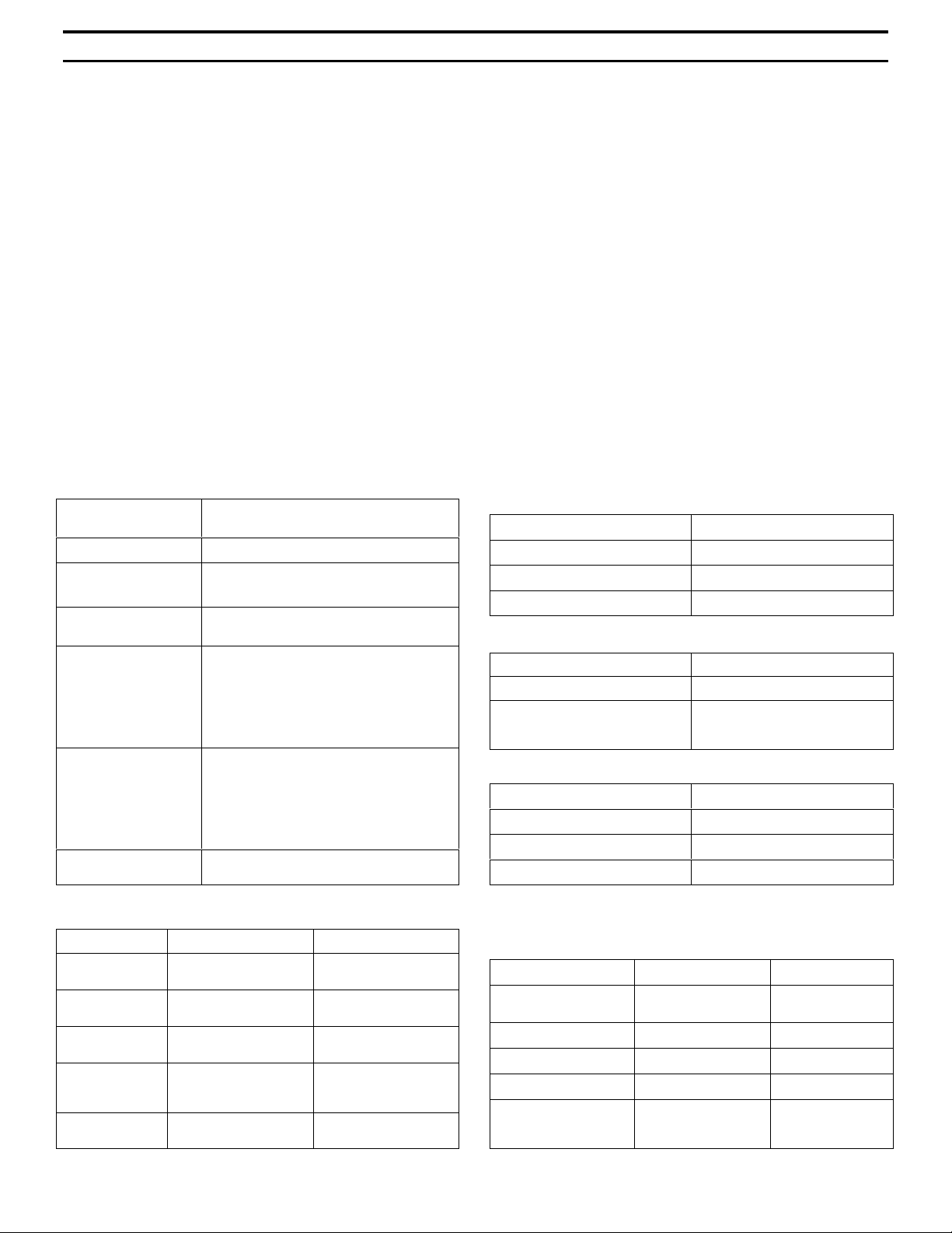
UC1
UC WIRELESS SYSTEM COMPONENTS
UC2
Specifications
RF Carrier Frequency Range
692–862 MHz, depending on locale
Working Range
152.4 m (500 ft), minimum, under typical conditions; 487.6 m
(1600 ft ) line of sight
NOTE: Actual working range depends on RF signal absorption,
reflecti on and interference.
Audio Frequency Response
45 to 15,000 Hz, ±2 dB.
NOTE: Overall system frequency response depends on the microphone element
Gain Adjustment Range
UC1: –6 to 34 dB
UC2: –6 to 26 dB
Modulation
±15 ±45kHz deviation, depending on RF range; compressorexpander system with pre-and de-emphasis
UC4
RF Power Output
10 mW – 50 mW typical, depending on RF range
Dynamic Range
>85 dB or >100 dB, depending on RF range; A-weighted
Receiver Audio Output Level (Maximum)
+5 dBu typical, unbalanced output
+14 dBu typical, balanced output
RF Sensitivity
UC4: –108 dBm at 12 dB SINAD
Image Rejection
90 dB typical
Spurious Rejection
70 dB typical
Ultimate Quieting (ref. 40 kHz deviation)
>100 dB, A-weighted
2002, Shure Incorporated
TL1024(BH)
Page 2
UC WIRELESS SYSTEM
Specification Sheet
Audio Polarity
Positive pressure on microphone diaphragm (or positive voltage applied to tip of WA302 phone plug) produces positive
voltage on pin 2 with respect to pin 3 of low impedance output
and the tip of the high impedance
1
/4-inch output
System Distort ion
(ref. ±40 kHz deviation, 1 kHz modulation)
0.4% Total Harmonic Distortion typical
Power Requirements
UC1, UC2: 9V alkalin e battery (Duracell MN1604 recommended); Nicad optional
UC4: 15 Vdc , 600 mA 50/60 Hz
Power Consumption: 600 mA x 15 V, maximum
Transmitter Battery Life (Typical)
8 hours (with Duracell MN1604 9V alkaline battery)
Operating Temperature Range
-7° to 49° C (20° to 120° F) NOTE: Battery characteristics
may limit this range.
Overall Dimensions
UC1: 99.06 mm L x 63.50 mm W x 22.86 mm D (3–29/32 L x
2–1/2 W x 29/32 in. D)
UC1 Transmitter Input (Figure 1)
Connector:
Input Configuration: Unbalanced, active
Actual Impedance:
Maximum Input Level:
Miniature connector
(TA4F) Pin Assignments:
LEMO Connector
Pin Assignments:
Voltage for Remote
Power:
4-Pin female miniature connector (T A4F)
or LEMO connector (optional)
18 kΩ with lavalier microphone
1 MΩ with instrument cable
9 Vp–p (10 dBV) for 1% THD at minimum
gain setting using 1 kHz signal.
Pin 1: Tied to Ground
Pin 2: Tied to +5 V
Pin 3: Tied to Audio
Pin 4: Tied thru 20kΩ Resistor to Ground.
(On instrument adapter cable, Pin 4 floats)
Pin 1: Tied to Pin 3 and 10 kW to Ground
Pin 2: +5V
Pin 3: Tied to Pin 1
Pin 4: Tied to Shield (Ground for Positive
Bias)
+5 V supplied to microphone cartridge
UC2/58:241.30 mm L x 50.8 mm Dia. (9–1/2 L x 2 in. Dia.)
UC2/BETA 58: 241.30 mm L x 50.80 mm Dia. (9–1/2 L x 2 in.
Dia.)
UC2/87:215.90 mm x 50.80 mm Dia. (8–1/2 L x 2 in. Dia.)
UC2/BETA 87: 215.90 mm L x 50.8 mm Dia. (8–1/2 L x 2 in.
Dia.)
UC4: 44.50 mm H x 197.40 mm W x 214.30 mm D (1–3/4 L x
7.77 W x 8.44 in. D)
Net Weight
UC1: 73.50 g (2.59 oz.) without battery
UC2/58, U2/BETA 58: 311.9 g (11 oz.) without battery
UC2/87, U2/BETA 87: 198.5 g (7 oz.) without battery
UC4: 1.22 kg (2 lbs, 11 oz.)
Certification
UC1, UC2: RA Type Approved to ETS 300 445; meets requirements of MPT 1350.
UC4: RA Type Approved to ETS 300 445; meets requirements of MPT 1350. Approved to ETS 300 445. Meets Low
Voltage Directive.
UC Type Approved and EMC Approved systems are eligible
to carry the CE marking.
UC1 Transmitter Output
Antenna:
Actual Impedance:
Nominal Output Level:
Maximum Output Level:
Flexible 1/4 wave wire
50 Ω
+10 dBm
+10 dBm
UC2 Transmitter Input
Input Configuration: Unbalanced, active
Actual Impedance: 25 kΩ
Maximum Input Level: 9 Vp–p (10 dBV) for 1% THD at
minimum gain setting using 1
kHz signal.
UC2 Transmitter Output
Antenna:
Actual Impedance:
Nominal Output Level:
Maximum Output Level:
Internal dipole
50 Ω
+10 dBm
+10 dBm
UC4 Receiver Input
Connector: Antenna Power Input
Connector
Type:
Actual
Impedance:
Nominal Input
Level:
Maximum Input
Level:
Pin
Assignments:
BNC dc style
50 Ω ––
–95 to –30 dBm 15 Vdc
+6 dBm
(–20 dBm
recommended)
Shell = Ground
Center = Signal
17 Vdc
Center pin positive
UC4 Receiver Output
Connector: High Z Audio Low Z Audio
Output
Configuration:
Actual Impedance: 1 kΩ 44Ω
Nominal Input Level: –– ––
Output Level: 5 dBu maximu m 14 dBu maximum
Pin Assignments: Tip = Hot
2
Unbalanced Balanced
Ring/ Sleeve = Gnd
1 = Ground
2 = Hot
3 = Hot
Page 3

UC WIRELESS SYSTEM
Specification Sheet
UC1 MIC JACK BOARD
500 Ω
27 pF
20K Ω
500 Ω
27 pF
UC1
MICROPHONE
ELEMENT
2
2
4
4
3
3
1
1
NOTE: LA VALIER MIC TIES PINS 3 AND 4 TOGETHER; GUITAR CABLE DOES NOT.
UC1L (LEMO 4 PIN)
MIC JACK BOARD
1
2
10K Ω
3
4
499 Ω
499 Ω
AUDIO
27 pF
BIAS
27 pF
SHIELD
Figure 1
FURNISHED ACCESSORIES
Microphone Stand Adapter (UC2) WA370A
Zipper Bag (UC1) 26A13
Zipper Bag (UC2) 26A14
Screwdriver 80A498
1/4 Wave Antenna UA400
+5 V
AUDIO
GROUND
OPTIONAL ACCESSORIES
Instrument Adapter Cable (UC1) WA302
4–Pin Female Miniature Connector, TA4F (UC1) WA330
In-Line Audio Switch (UC1) WA360
1.8 Meter (6 ft) Receiver-Mixer Cable (
/4” phone
WA410
1
to XLR)
0.6 Meter (2 ft.) Antenna Extension Cable UA802
7.6 Meter (25 ft) Antenna Extension Cable UA825
15.2 (50 ft) Meter Antenna Extension Cable UA850
In–Line Active Remote Antenna Kit (838 – 862
UA830KK
MHz) (If using the UA845–KK Antenna/Power Distribution System)
REPLACEMENT PARTS
Hardware Kit (screwdriver, mounting feet, cable
clamps)
Bulkhead Adapters for Front–Mounting Antennas 95A8647
15 Vdc Power Cord (230 V AC) PS40UK
SM58 Cartridge with Grille (UC2/58) R158
BETA 58A Cartridge with Grille (UC2/BET A 5 8) R179
SM87 Cartridge with Grille (UC2/87) R165
BETA 87A Cartridge with Grille (UC2/BETA 87A) R166
BETA 87C Cartridge with Grille (UC2/BETA 87C) RPW100
Matte Silver Grille (UC2/58) RK143G
90VX1371
Antenna/Power Distribution System, 230 V ac UA845-KK
Directional Antenna for UC4 Receiver (If using the
UA870KK
UA845–KK Antenna/Power Distribution System)
Remote Mute Switch for UC1 UA101
Passive Antenna Splitter/Combiner UA220
1/2 Wave Omnidirectional Antenna for UC4 Re-
UA820A
ceiver
Remote Mount Antenna Kit UA500
Front Mount Antenna Kit UA600
Matte Silver Grille (UC2/BETA 58) RK265G
Matte Silver Grille (UC2/BET A 87A) RK313G
Black Grille (UC2/87C) RK214G
Black Grille (UC2/BETA 58) RK323G
Black Grille (UC2/BET A 87A) RK324G
Belt Clip (UC1) 44A8013
Mounting Brackets, Long 53A8458
Mounting Brackets, Short 53A8454
Mounting Brackets, Link 31A8138
UC4 Logic Connector (Phoenix) 95A8580
3
Page 4

UC WIRELESS SYSTEM
Specification Sheet
Architects’ and Engineers’ Specifications
The wireless system shall operate in the UHF band between 692 MHz and 862 MHz, with the specific range being dependent on the
user’s locale. The system shall include the option of changing the operating frequency in order to avoid RF interference, enabling up to 16
systems to operate simultaneously in the same location. Preconfigured group, channel and frequency setups shall be available to ensure
that multiple systems in use do not interfere with one another.
All transmitters shall be powered by a single 9V battery and shall have a power on/off switch, an optional mute switch, an LED indicating
that power is on, and an LED indicating low battery power. Available transmitters shall include: a body pack for use with electric guitars,
basses, and other electric instruments, as well as lavalier or headworn microphones; and a handheld microphone for vocals.
The receiver shall be a half-rack (HR) design. Mounting hardware for single or dual rack mounting shall be supplied. The system shall
use technology such as MARCAD signal combining circuitry to improve reception, minimize signal dropouts, and achieve the best possible
signal–to–noise ratio. An equalizer, tone key squelch, and noise squelch circuitry shall be built in to the system to provide optimal sound
quality and minimize unwanted noise. The receiver shall include dual RF meters, an audio level meter , and a logic in/out terminal for interfacing with external devices. The receiver shall have a volume control and an adjustable noise squelch control.
The system shall be the Shure UC Wireless.
4
 Loading...