

Page 1
USER GUIDE SUPPLEMENT
UB (692–716 MHz)
UHF WIRELESS SYSTEM
SPECIFICATIONS
RF Carrier Frequency Range
692–716 MHz
Working Range
U1, U2: 152.4 m, minimum, under typical conditions; 487.6 m line of sight
NOTE: Actual working range depends on RF signal absorption, reflection and interference
Audio Frequency Response
50 to 15,000 Hz, ±2 dB. NOTE: Overall system frequency response depends on the microphone
element
Gain Adjustment Range
U1: 0 to 40 dB
U2: 0 to 26 dB
Modulation
±45 kHz deviation compressor-expander system with pre-and de-emphasis
RF Power Output
U1, U2: 10 mW maximum
50 mW maximum
Dynamic Range
>102 dB, A-weighted
RF Sensitivity
U4S U4D
–110 dBm
12 dB SINAD
–105 dBm
30 dB SINAD
Image Rejection
90 dB typical
Spurious Rejection
75 dB typical
Ultimate Quieting (ref. 45 kHz deviation)
>100 dB, A-weighted
Audio Polarity
Positive pressure on microphone diaphragm (or positive voltage applied to tip of WA302
phone plug) produces positive voltage on pin 2 with respect to pin 3 of low impedance output
and the tip of the high impedance 1/4-inch output
System Distortion (ref. ±45 kHz deviation, 1 kHz modulation)
0.3% Total Harmonic Distortion typical
Power Requirements
U1, U2: 1.5V AA alkaline battery recommended; Nicad battery optional
U4: 90 to 230 Vac , 50/60 Hz
Power Consumption:
U4S: 9.6 W min., 13.2 W max.
U4D: 12 W min.,16 W max.
UA840: 15 W min., 16 W max.
Battery Life (Typical)
U1, U2: 12 hours (with Duracell MN1500 1.5V AA alkaline battery)
E2003, Shure Incorporated
27D8670 (CC)
–107 dBm
12 dB SINAD
–102 dBm
30 dB SINAD
Printed in U.S.A.
Page 2
Operating Temperature Range
-20° to 50° C NOTE: Battery characteristics may limit this range
Overall Dimensions
U1: 92.2 mm L x 64.7 mm W x 24.2 mm D
U2/58:254 mm L x 50.8 mm Dia.
U2/BETA 58: 254 mm L x 53.2 mm Dia.
U2/87:228.6 mm x 49.2 mm Dia.
U2/BETA 87: 216 mm L x 50.8 mm Dia
U4S/U4D: 44.5 mm H x 482.6 mm W x 295.3 mm D
Net Weight
U1: 175.2 g without battery
U2/58, U2/BETA 58: 375.6 g without battery
U2/87, U2/BETA 87: 303.1 g without battery
U4S: 3.30 kg
U4D: 3.85 kg
Certification
U1, U2: Type Accepted under FCC Part 74. FCC ID DD4U1B and DD4U2B. Certified by IC in
Canada under TRC-78
U4S, U4D: UL and cUL Listed to UL 813 and CSA C22.2 No. 1. Approved under the
Declaration of Conformity provision of FCC Part 15; Certified by IC in Canada under
TRC-78. VDE Certified to EN 60 950.
UHF Type Approved and EMC Approved systems are eligible to carry the CE marking.
FCC Statement
The U4 Receiver complies with Part 15 of the FCC rules. Operation is subject to the following
two conditions: (1) this device does not cause harmful interference, and (2) this device must
accept any interference received, including interference that may cause undesired operation.
Licensing Statement
A user license may be required for operation. Contact the communications authority in your
country for more information.
Modifications to Approved Equipment
Changes or modifications not expressly approved by Shure Incorporated could affect
compliance with telecommunications standards, thereby voiding the user’s authority to
operate this product.
U1 Transmitter Input
Connector:
Input Configuration: Unbalanced, active
Actual Impedance:
Maximum Input Level:
4-Pin Female Miniature
Connector TA4F Pin
Assignments:
LEMO Connector
Pin Assignments:
Voltage for Re mo te Power: +5 V supplied to microphone cartridge
4-Pin Female Miniature Connector (TA4F) or
6 Vp–p (+7 dBV) for 1% THD at minimum gain setting
Pin 4: Tied to Shield (Ground for Positive Bias)
LEMO connector (optional)
18 kΩ with lavalier microphone
1 MΩ with instrument cable
using 1 kHz signal.
Pin 1: Tied to Ground
Pin 2: Tied to +5 V
Pin 4: Tied thru 20kΩ Resistor to Ground.
(On instrument adapter cable, Pin 4 floats)
Pin 1: Tied to Pin 3 and 10 kΩ to Ground
Pin 3: Tied to Audio
Pin 2: +5V
Pin 3: Tied to Pin 1
2
Page 3
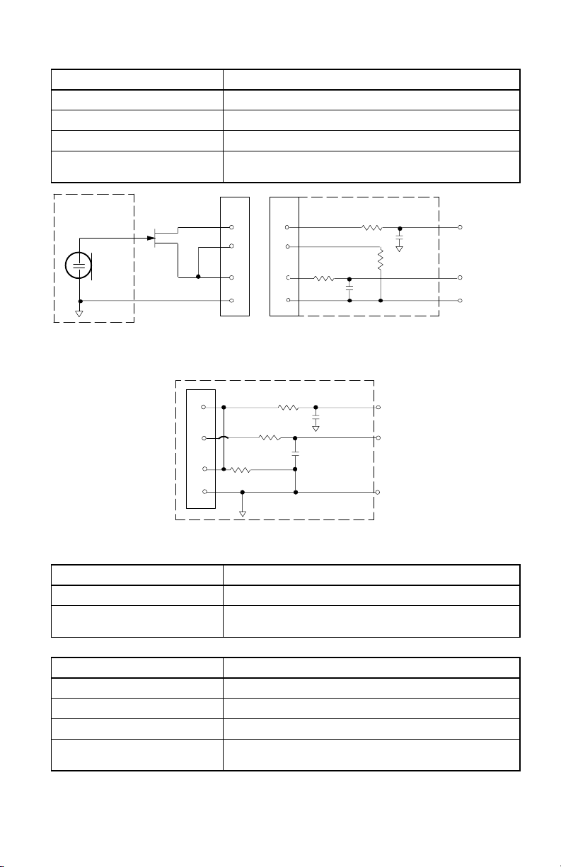
U1 Transmitter Output (Figure 1)
Connector: SMC
Actual Impedance: 50 Ω
Nominal Output Level: +10 dBm
Maximum Output Level: +11 dBm
Pin Assignments: Shell = Ground
Center = Signal
MICROPHONE
ELEMENT
NOTE: LAVALIER MIC TIES PINS 3 AND 4
TOGETHER; GUITAR CABLE DOES NOT.
1
2
3
4
2
2
4
4
3
3
1
U1L (LEMO 4 PIN) MIC JACK BOARD
10K Ω
1
499 Ω
499 Ω
U1/U1H MIC JACK BOARD
500 Ω
27 pF
20K Ω
500 Ω
27 pF
AUDIO
27 pF
BIAS
27 pF
SHIELD
FIGURE 1
U2 Transmitter Input
Input Configuration: Unbalanced, active
Actual Impedance: 20 kΩ
Maximum Input Level: 3 Vp–p (0.5 dBV) for 1% THD at minimum gain setting
U2 Transmitter Output
Connector: SMC
Actual Impedance: 50 Ω
Nominal Output Level: +10 dBm
Maximum Output Level: +11 dBm
Pin Assignments: Shell = Ground
using 1 kHz signal.
Center = Signal
+5 V
AUDIO
GROUND
3
Page 4

U4S and U4D Receiver Input
Connector:
Connector Type: BNC IEC 25–Pin D
Actual Impedance: 50 Ω –– ––
Nominal Input
Level:
Maximum Input
Level:
Pin Assignments: Shell = Ground
Voltage for
Remote Power:
U4S and U4D Receiver Output
Connector: Monitor Power
Output
Configuration:
Actual
Impedance:
Nominal
Input Level:
Pin
Assignments:
Voltage/
Current/
Phantom
Power
Protection?
*Output Level: Microphone Level = Line Level – 30 dB
Unbalanced
mono, 1/4 inch
Tip = Hot
Ring = Hot
Sleeve = Gnd
Antenna Power Input Network Interface
–95 to –30 dBm 90–230 VAC,
+6 dBm
(–20 dBm
recommended)
Center = Signal
12 Vdc, 150 mA
maximum
Output
–– Un-
300 Ω –– 1 kΩ 30 Ω See
–– 90 to 230
Yes –– Yes Ye s 5V, 700 mA
VAC , 5A
IEC
Standard
50/60 Hz
230 VAC, 50/60 Hz ––
IEC Standard ––
–– 5V, 700 mA max.
High Z
Audio
balanced
–– –– CMOS
Tip = Hot
Ring/
Sleeve =
Gnd
Balanced See
1 = Ground
Low Z
Audio*
2 = Hot
3 = Hot
CMOS Logic
Network
Interface
Appendix
Appendix
Logic
See
Appendix
resettable
polyfuse
4
Page 5

FURNISHED ACCESSORIES
Microphone Stand Adapter (U2) WA370A. . . . . . . . . . . . . . . . . . . . . . . . . . . . . . . . . . .
Zipper Bag (U1) 26A13. . . . . . . . . . . . . . . . . . . . . . . . . . . . . . . . . . . . . . . . . . . . . . . . . . .
Zipper Bag (U2) 26A14. . . . . . . . . . . . . . . . . . . . . . . . . . . . . . . . . . . . . . . . . . . . . . . . . . .
Screwdriver 80A498. . . . . . . . . . . . . . . . . . . . . . . . . . . . . . . . . . . . . . . . . . . . . . . . . . . . .
Coaxial Antenna Cable (2 ft) UA802. . . . . . . . . . . . . . . . . . . . . . . . . . . . . . . . . . . . . . . .
1/2 Wave Antenna UA820A. . . . . . . . . . . . . . . . . . . . . . . . . . . . . . . . . . . . . . . . . . . . . . . .
Transmitter Carrying Case 65A8257. . . . . . . . . . . . . . . . . . . . . . . . . . . . . . . . . . . . . . . .
Carrying Case Insert 29B1577. . . . . . . . . . . . . . . . . . . . . . . . . . . . . . . . . . . . . . . . . . . . .
OPTIONAL ACCESSORIES
Instrument Adapter Cable (U1) WA302. . . . . . . . . . . . . . . . . . . . . . . . . . . . . . . . . . . . . .
4-Pin Female Miniature Connector,TA4F (U1) WA330. . . . . . . . . . . . . . . . . . . . . . . . .
In-Line Audio Switch (U1) WA360. . . . . . . . . . . . . . . . . . . . . . . . . . . . . . . . . . . . . . . . . . .
1.8 Meter (6 ft) Receiver-Mixer Cable (
1
/4” phone to XLR) WA410. . . . . . . . . . . . . . . .
7.6 Meter (25 ft) Antenna Extension Cable UA825. . . . . . . . . . . . . . . . . . . . . . . . . . . .
15.2 (50 ft) Meter Antenna Extension Cable UA850. . . . . . . . . . . . . . . . . . . . . . . . . . .
In–Line Active Remote Antenna Kit (619 – 716 MHz) UA830UB. . . . . . . . . . . . . . . .
Antenna/Power Distribution System, 120 Vac UA845UB. . . . . . . . . . . . . . . . . . . . . . .
Directional Antenna UA870UB. . . . . . . . . . . . . . . . . . . . . . . . . . . . . . . . . . . . . . . . . . . . .
REPLACEMENT PARTS
Hardware Kit (screwdriver, mounting feet, cable clamps) 90VL1371. . . . . . . . . . . . .
Bulkhead Adapters for Front–Mounting Antennas 95A8647. . . . . . . . . . . . . . . . . . . .
120 VAC Power Cord (U.S. mains connector) 95A8389. . . . . . . . . . . . . . . . . . . . . . . .
304 mm (12 in.) Daisy–Chain Power Cord (120 V) 95A8570. . . . . . . . . . . . . . . . . . . .
SM58
Cartridge with Grille (U2/58) R158. . . . . . . . . . . . . . . . . . . . . . . . . . . . . . . . . . .
BETA 58A Cartridge with Grille (U2/BETA 58) R179. . . . . . . . . . . . . . . . . . . . . . . . . .
SM87 Cartridge with Grille (U2/87) R165. . . . . . . . . . . . . . . . . . . . . . . . . . . . . . . . . . . .
BETA 87A Cartridge with Grille (U2/BETA 87) R166. . . . . . . . . . . . . . . . . . . . . . . . . . .
BETA 87C Cartridge with Grille (U2/BETA 87) RPW100. . . . . . . . . . . . . . . . . . . . . . . .
Matte Silver Grille (U2/58) RK143G. . . . . . . . . . . . . . . . . . . . . . . . . . . . . . . . . . . . . . . . . .
Matte Silver Grille (U2/BETA 58) RK265G. . . . . . . . . . . . . . . . . . . . . . . . . . . . . . . . .
Matte Silver Grille (U2/BETA 87 RK313G. . . . . . . . . . . . . . . . . . . . . . . . . . . . . . . . . .
Black Grille (U2/87) RK214G. . . . . . . . . . . . . . . . . . . . . . . . . . . . . . . . . . . . . . . . . . . . . . .
Black Grille (U2/BETA 58) RK323G. . . . . . . . . . . . . . . . . . . . . . . . . . . . . . . . . . . . . . . . . .
Black Grille (U2/BETA 87) RK324G. . . . . . . . . . . . . . . . . . . . . . . . . . . . . . . . . . . . . . . . . .
Belt Clip (U1) 53A8247A. . . . . . . . . . . . . . . . . . . . . . . . . . . . . . . . . . . . . . . . . . . . . . . . . .
Antenna (U1) 95A8646. . . . . . . . . . . . . . . . . . . . . . . . . . . . . . . . . . . . . . . . . . . . . . . . . . .
Antenna (U2–UB) 95C2029. . . . . . . . . . . . . . . . . . . . . . . . . . . . . . . . . . . . . . . . . . . . . . . .
5
Page 6
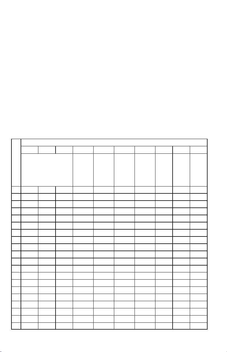
FREQUENCY SELECTION GUIDE
The Shure UHF Wireless System is designed for maximum flexibility and versatility
in a variety of applications. Up to 20 Shure UHF Wireless Systems can be operated
simultaneously in a single installation using the frequency compatibility groups.
Please contact Shure Incorporated if you need additional information or assistance in
frequency selection and setup.
NOTE: Shure recommends that you maintain a 500 kHz separation between each
receiver channel in the U4D dual channel receivers. Please contact the Shure Customer Service Department (1–800–434–3350) if you need additional information or
assistance in frequency selection and setup.
Compatibility Groups
The Shure UHF Wireless System includes 10 groups of compatible channels. If you
are using more than one receiver in the same area, we recommend that you set the
receivers to different frequencies within the same group.
Compatible Frequency List
The following table lists the frequencies in each of the 10 compatibility groups.
GROUP
GRP 1 GRP 2 GRP 3 GRP 4 GRP 5 GRP 6 GRP 7 GRP 8 GRP 9 GRP 10
TV CHANNELS 51, 52, 53, 54
C
H
A
N
N
E
L
1 692.500 692.125 692.250 698.250 692.500 692.125 692.125 715.625 715.500 715.125
2 693.375 692.625 695.125 698.875 693.250 693.500 693.125 714.625 714.250 714.125
3 694.500 693.375 695.875 700.000 694.250 694.125 693.625 714.000 712.750 713.625
4 695.000 694.375 697.125 700.625 695.000 695.125 694.625 713.125 712.000 711.875
5 697.000 695.125 698.625 701.500 695.500 695.750 695.875 712.000 710.875 711.125
6 698.000 698.875 699.875 702.000 696.250 697.000 696.500 710.250 710.375 709.875
7 699.250 699.375 700.625 702.750 697.250 697.750 697.875 708.125 708.250 709.000
8 699.750 700.625 701.625 703.750 698.000 699.125 698.875 707.625 707.125 708.375
9 702.875 703.125 702.375 704.375 704.500 700.125 700.500 706.750 704.125 707.375
10 703.750 704.625 703.625 709.000 706.000 701.625 701.500 706.250 702.500 706.625
11 705.500 706.375 704.375 709.500 706.750 702.250 703.375 703.625 700.625 705.125
12 707.500 707.125 708.375 710.250 707.250 710.125 703.875 702.625 699.000 700.875
13 708.500 707.625 709.375 711.250 708.750 710.625 705.875 701.875 698.125 700.000
14 709.000 708.375 709.875 711.875 709.500 711.500 706.875 699.875 697.625 699.375
15 709.750 710.875 710.750 712.750 711.250 712.125 707.625 696.375 695.875 697.625
16 710.250 711.500 711.875 713.250 712.000 713.125 708.125 695.875 694.875 696.875
17 712.750 712.500 713.375 714.000 713.250 713.875 709.125 694.625 694.375 696.375
18 713.750 713.125 714.125 715.000 714.250 714.375 709.625 693.750 693.250 694.625
19 714.500 714.375 714.625 715.625 715.000 715.250 692.375 692.500 694.125
20 715.500 715.125 715.625 715.875 693.125
OPEN
TV
CHANNEL
51
PRESENT
TV
CHANNEL
52
PRESENT
TV
CHANNEL
53
PRESENT
TV
CHANNEL
54
PRESENT
6
Page 7

Declaration of Conformity
We of
Shure Incorporated
222 Hartrey Ave.
Evanston IL 60202–3696 U.S.A.
847–866–2200
declare under our sole responsibility that the following products,
Model: U4S Name: UHF Diversity Receiver
Model: U4D Name: UHF Dual Channel Diversity Receiver
were tested and found to comply with Part 15 of the FCC rules.
Operation is subject to the following two conditions: (1) this device may not cause harmful interference, and (2)
this device must accept any interference received, including interference that may cause undesired operation.
Testing was completed by the following NVLAP or A2LA accredited laboratory:
D.L.S. Electronic Systems, Inc.
1250 Peterson Drive
Wheeling, Illinois 60090, U.S.A.
At the test location of
D.L.S. Electronic Systems, Inc.
166 South Carter
Genoa City, Wisconsin, 53128, U.S.A.,
Test Sites Number 1 and 2
Shure Inc., Manufacturer.
Signed:
Name, Title: Craig Kozokar, Senior Quality Engineer
Additional Information for this Shure Wireless System
This Shure wireless transmitter is accepted under FCC Part 74 and/or Part 90.
IMPORTANT: Licensing of Shure wireless microphone equipment is the user’s responsibility, and licensability depends on the user’s classification and application, and on the selected frequency. Shure
urges the user to consult the appropriate telecommunications authority before choosing and ordering frequencies.
Changes or modifications not expressly approved by Shure Inc. could void your authority to operate this equipment.
The information on this page supersedes the corresponding information in your Shure user’s guide.
Date: June 15, 1999
7
Page 8

SHURE Incorporated Web Address: http://www.shure.com
5800 W. Touhy Avenue, Niles, IL 60714-4608, U.S.A.
Phone: 800-257-4873 Fax: 847-866-2279
In Europe, Phone: 49-7131-72140 Fax: 49-7131-721414
In Asia, Phone: 852-2893-4290 Fax: 852-2893-4055
Elsewhere, Phone: 847-866-2200 Fax: 847-866-2585
 Loading...