

Page 1
General Description
The UA834 provides more flexibility in wireless installations by increasing
the allowable length of cable runs between a receiver and antenna. Antennas
may be placed closer to the stage, or installed on ceilings and walls that
maintain a better line of sight with the transmitter.
Features
• Low-noise signal amplifier compensates for insertion loss in coaxial cable
• Compatible with Shure Wireless Systems. Also may be used with Shure
UA845 and UA844 Antenna Distribution Systems
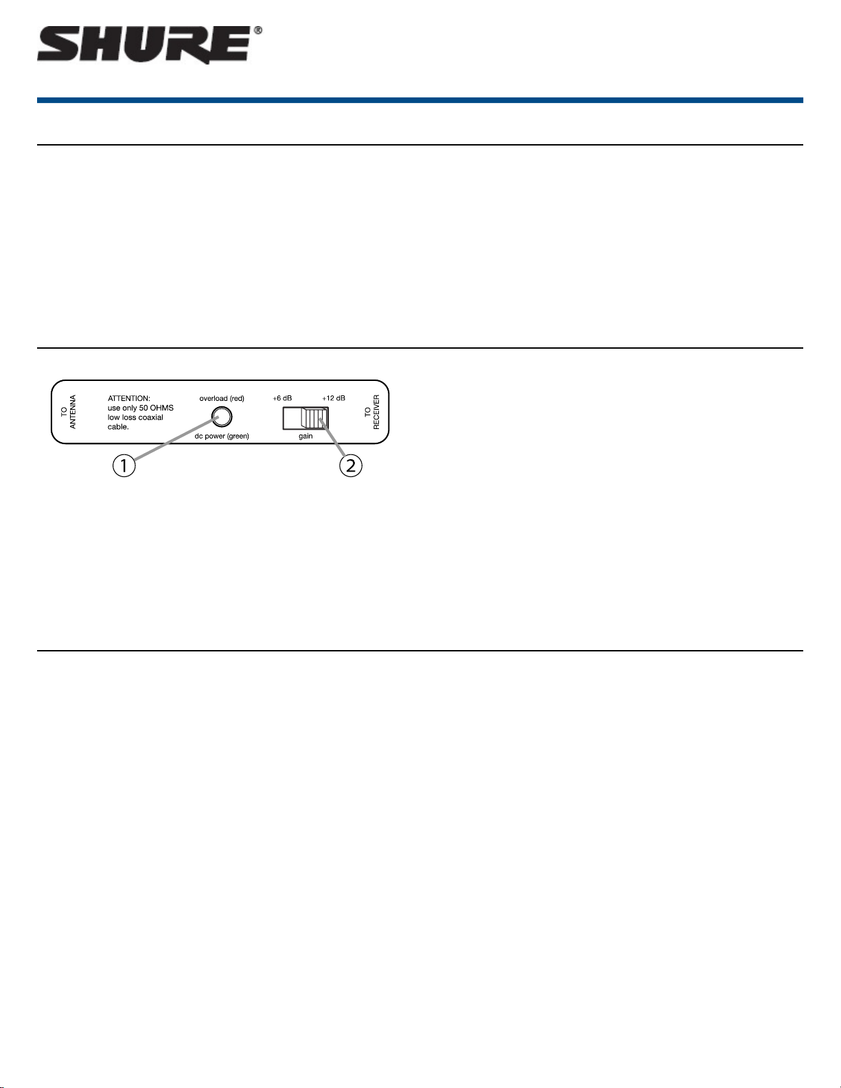
Indicators and Settings
① DC POWER/RF OVERLOAD
Green:Indicates it is receiving power from the antenna input on the receiver
or combiner.
Red: Signal from the antenna (at the TO ANTENNA input) is too strong.
Remove the inline amplifier or move it further down the cable run.
② GAIN
Set the gain switch to +6 dB for shorter cable runs, and +12 dB for longer
runs.
UA834
In-Line Antenna Amplifier
• Integrated threaded adapter mounts easily to microphone stands or the
supplied surface-mount bracket
• Two-position gain selector switch
• LED indicator for RF signal overload
• Shure quality, ruggedness, and reliability
NOTE:Antenna amplifiers are intended to compensate for signal loss in cables, not for increasing the range of the antenna. Attempting to “boost” the
signal beyond nominal levels only results in overloading the circuit and reducing performance.
RF Overload
RF overload can occur at the input to the inline amplifier or at the input to the
receiver. An overload at either point degrades the signal.
When there is an RF overload indicator on the inline amplifier, the amplifier
might not be necessary, or it should be placed further down the cable run at
a midpoint between the antenna and receiver. The gain switch only affects
output gain, and cannot compensate for input overload at the amplifier.
If there is an RF overload signal on the receiver, reduce the gain on the inline
amplifier, or move it further up the cable run so there is more cable between
the receiver and the amplifier. Note that the overload level for the amplifier
might be greater than that for the receiver input, so it cannot be used to indicate whether the signal will overload the receiver at that point in the cable
run.
Installation
Connect between the antenna and receiver (or antenna distribution system), as shown. The DC POWER LED illuminates green when the receiver is powered
on.
• Use Shure low-loss coaxial antenna cable (or any 50 ohm, low-loss cable.
• The quality of the cable, not just the length, contributes to signal loss. A lighter grade 50 foot cable may require more gain than a 100 foot, low-loss cable.
• Active antennas, such as the UA874, have a built-in amplifier, and may not require additional amplification.
Caution:Use only Shure antenna accessories to ensure the best operation. Do not use splitters, combiners, or antennas that provide a DC ground. If necessary,
use a BNC DC block device (compatible with the receiver RF band).
1/4©2016 Shure Incorporated
Page 2
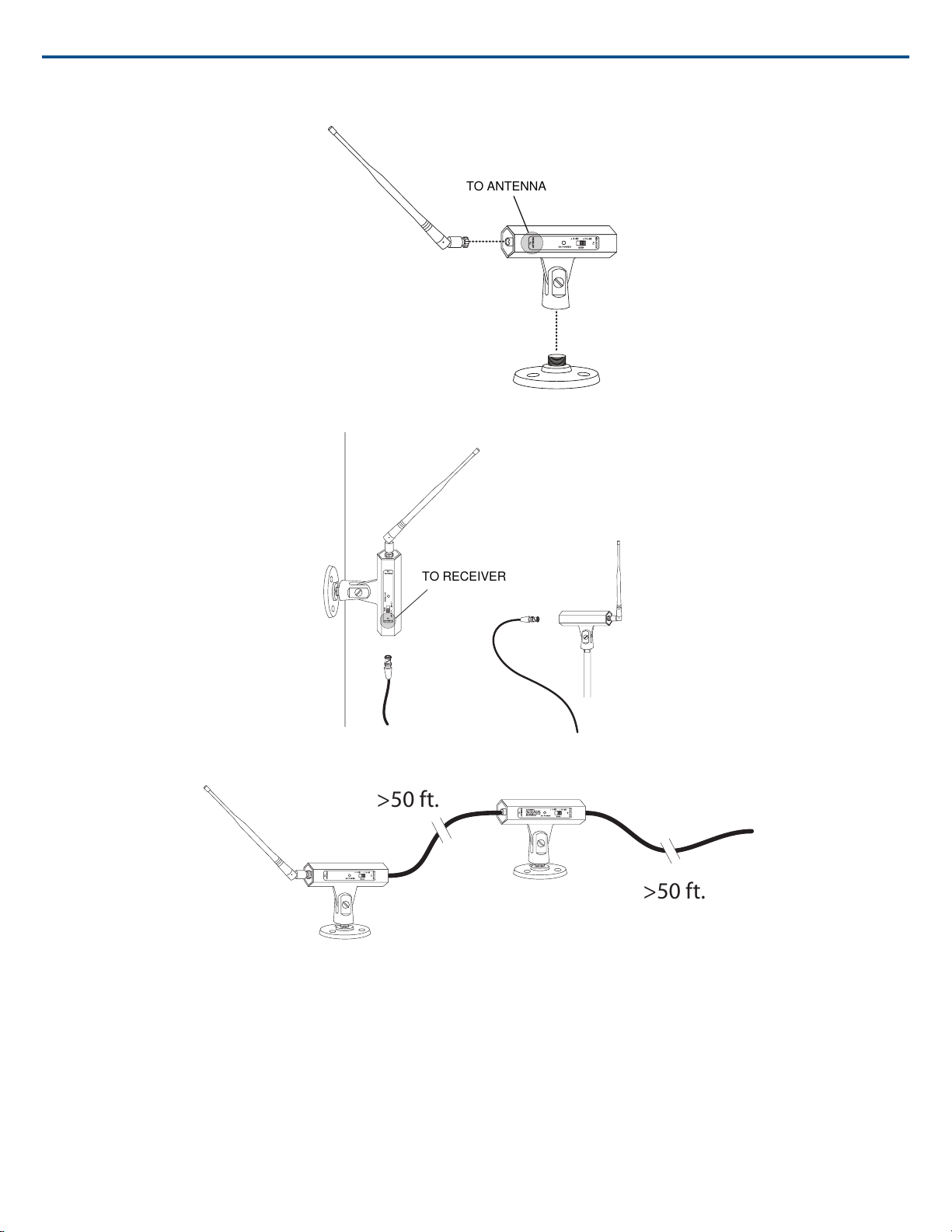
TO ANTENNA
Attach the antenna to the connector labeled TO ANTENNA
TO RECEIVER
>50 ft.
>50 ft.
Shure IncorporatedUA834 In-Line Antenna Amplifier
Use the supplied surface-mount bracket on walls or ceilings, or mount on a standard microphone stand.
Use a maximum of two in-line antenna amplifiers for extremely long cable runs or for two runs of lighter-grade cable, as shown
Cable Maintenance
To maintain top performance for antenna cables:
• Avoid sharp bends or kinks in the cables.
• Do not deform cables with makeshift clamps, such as bending a nail over the cable.
• Do not use in permanent outdoor installations.
• Do not expose to extreme moisture.
Selecting Antenna Cables
Use 50 ohm low-loss coaxial cable, such as RG-8U. Shure offers pre-terminated antenna cables ranging from 6 to 100 feet.
2016/10/252/4
Page 3

Shure IncorporatedUA834 In-Line Antenna Amplifier
NOTE:When ordering cables from Shure, select the low-loss "Z" models (available for longer cables) when using frequency bands above 1000 MHz.
Antenna Placement
Use the following guidelines when mounting antennas:
• Antennas and receivers must be from the same band.
• Mount antennas at least one wavelength (two feet) apart.
• Position antennas so there is nothing obstructing a line of sight to the
transmitter (including the audience).
• Keep antennas away from metal objects.
Important: Always perform a "walk around" test to verify coverage before
using a wireless system during a speech or performance. Experiment with
antenna placement to find the optimum location. If necessary, mark "trouble
spots" and ask presenters or performers to avoid those areas.
Find More Information Online
For more information, visit http://www.shure.com
Setting Gain
The gain setting should only be used to compensate for the calculated cable
signal loss. Additional signal gain does not mean better RF performance.
Too much gain actually reduces reception range and the number of available
channels. This is because Shure receivers are optimized to deliver the best
performance when the sum of signal gain and cable loss equals 0 dB. Additional gain just amplifies everything in the RF range—including interference
and ambient RF noise. It cannot selectively increase the signal from the
transmitter.
• Use the lowest gain setting necessary to achieve good reception of the
transmitter RF signal, as indicated on the receiver’s RF LED or meter.
• Only increase the gain setting to compensate for the calculated cable
loss.
Specifications
Frequency Range
174–216 MHzUA834V
470–902 MHzUA834WB
902–960 MHzUA834XA
1240–1260 MHzUA834Z16
1492–1525 MHzUA834Z17
1785–1805 MHzUA834Z18
Connector Type
BNC, Female
• The resulting signal level at the receiver (cable loss plus amplification)
should be within ±5 dB of the original signal level at the antenna.
Calculating Gain Settings
To calculate the required gain setting, obtain the cable manufacturer's
specification for signal loss. The rated loss usually varies with RF frequency
in addition to cable length.
Multiply the per 100 feet rating of the cable by cable length to determine
signal loss, and add gain as necessary to compensate. For example: a 50
ft. cable with rated loss of -12dB per 100 ft. would calculate as
(-12dB/100)*50 = -6dB and require +6dB of gain for a sum total of 0
dB loss.
Power Requirements
10 to 15 V DC bias from coaxial connection, 0.60–0.72 W
Signal Gain
±2 dB, Switchable
+6 dB +12 dB
Absolute Maximum RF Input
+5 dBm
RF Overload LED Threshold
±2 dB
-5 dBm
Impedance
50 Ω
Input Third-Order Intercept Point (IIP3)
>10 dBm
3/42016/10/25
Page 4

Shure IncorporatedUA834 In-Line Antenna Amplifier
Housing
Cast Aluminum, black painted finish
Dimensions
67 x 32 x 112 mm (H x W x D) Dimensions with Stand: 108 x 32 x 112 mm
Certifications
This product meets the Essential Requirements of all relevant European directives and is eligible for CE marking.
The CE Declaration of Conformity can be obtained from:
www.shure.com/europe/compliance
Authorized European representative:
Shure Europe GmbH
Headquarters Europe, Middle East & Africa
Department: EMEA Approval
Jakob-Dieffenbacher-Str. 12
75031 Eppingen, Germany
Phone: 49-7262-92 49 0
Fax: 49-7262-92 49 11 4
Email: info@shure.de
Net Weight
0.28 kg (9.8 oz.)Without Mounting Stand
0.42 kg (14.8 oz.)With Mounting Stand
Shure Incorporated 5800 West Touhy Avenue Niles, IL 60714-4608 USA Phone: +1-847-600-2000 Email: info@shure.com
4/4
 Loading...