

Page 1
Shure Brothers Incorporated
222 Hartrey Avenue
Evanston IL 60202-3696 U.S.A.
In Europe, Phone: 49-7131-72140 Fax: 49-7131-721414
Phone: 800-257-4873 Fax: 847-866-2279
Internationally, Phone: 847-866-2200 Fax: 847-866-2585
Web Address: http://www .shure.com
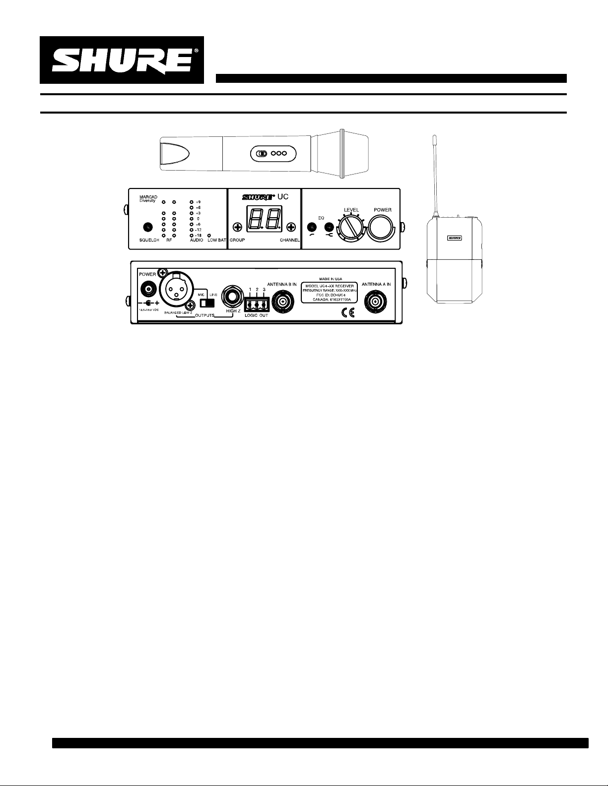
UC WIRELESS SYSTEM
AB
The Shure UC Wireless Sys tem is a fr equency–agile diversity sy stem operating in the UHF band. Both the receiver and the transmitter are synthesizer controlled via
Phase Locked Loop (PLL) circuitry for a clear, steady
signal. The half–rack spac e receiver mounts into a standard 19 inc h (482 mm) equipment rack.
Features
S UHF band operation for less interference
S Frequency–agility lets user change system frequency
if interf erence is encountered
S Over 100 user–selectable frequencies (international
versions may vary)
S Up to 16 systems can operate simultaneously (inter-
national versions may vary)
S Compact, 1/2 rack spac e receiver design
S Exclusive Shure MARCAD circuitry delivers signal
that is virtually free from drop outs
S Nosie Squelch Circuitry analyzes signal quality rather
than signal strength, virtually elilminating the possibility of noise bursts
S Tone Key Squelch that prevents unwanted noise
from entering the system, including the ’pop” noise
that occurs when the transmitter is turned on and off
S Extensive rf and audio metering
S Low transmitter battery warning LED on receiver
S Preconfigured Group/Channel and frequency for
simplified setup of multiple UC wireless systems
S Two Band EQ feature on receiver lets you fine tune
frequency response
Specification Sheet
S Receiver logic capability lets you control external
equipment
S Remote mute feature on bodypack; optional acces-
sory switch lets you externally mute bodypack
transmitter during performance
Components
S UC1 Body–Pack Transmitter with detachable lava-
lier microphone, headset, or instrument cable
or
S UC2 Handheld Microphone Transmitter with inter-
changeable microphone heads
and a
S UC4 MARCAD Diversity Receiver with external in–
line power supply (100/120/230 V ac) and antennas
Accessories
S UA101 Remote Mute Switch– Mutes audio and/or
rf from bodypack transmitter during performance
S UA220 Passive Antenna Splitter/Combiner Kit–
Splits two antennas for use with two diversity receivers and/or combines four antennas into two antenna
inputs
S UA845 Antenna Power/Distribution System–
Provides connection for up to five diversity receivers
and supplies power for to up to four receivers; uses
only two antennas
S UA500 Remote Mount Antenna Kit– Hardware
for remote mounting one 1/2 wave antenna
S UA600 Front Mount Antenna Kit– Front mounts
antennas for the receiver
E1998, Shure Brothers Incorporated
AL1344 (RC)
Printed in U.S.A.
Page 2

SYSTEM SPECIFICATIONS
RF Carrier Frequency Range
774–862 MHz (782–806 MHz for U. S. models)
Working Range
152.4 m (500 ft), minimum, under typical conditions;
487.6 m (1600 ft ) line of sight
NOTE: Actual working range depends on RF signal
absorption, reflection and interference
Audio Frequency Response
45 to 15,000 Hz, ±2 dB. NOTE: Overall system
frequency respons e depends on the microphone
element
Gain Adjustment Range
UC1: –6 to 34 dB
UC2: –6 to 26 dB
Modulation
±45kHz deviation compressor-expander system with
pre-and de-emphasis
(U.S. models only; internat ional models may vary)
RF Power Output
UC1, UC2: 50 mW, typical; international versions
may vary
Dynamic Range
>100 dB, A-weighted
Receiver Audio Output Level (Maximum)
+5 dBu typical, unbalanced output
+14 dBu typical, balanced output
RF Sensitivity
UC4: –108 dBm at 12 dB SINAD
Image Rejection
90 dB typical
Spurious Rejection
70 dB typical
Ultimate Quieting (ref. 45 kHz deviation)
>100 dB, A-weighted
Audio Polarity
Positive pres sure on microphone diaphragm (or
positive voltage applied to tip of WA302 phone
plug) produces pos it iv e voltage on pin 2 with
respect to pin 3 of low impedance output and the
tip of the high impedance 1/4-inch output
System Distortion (ref. ±45 kHz deviat i on, 1 kHz
modulation)
0.4% Total Harmonic Distortion typical
Power Requirements
UC1, UC2: 9V alkaline battery (Duracell MN1604
recommended); Nicad optional
UC4: 15 Vdc , 600 mA 50/ 60 Hz
Power Consumption: 600 mA x 15 V, maximum
Transmitter Battery Life (Typical)
8 hours (with Duracell MN1604 9V alkaline battery)
Operating Temperature Range
-7° to 49° C (20° to 120° F) NOTE: Battery
characteristics may limit this range
Overall Dimensions
UC1: 99.06 mm L x 63.50 mm W x 22.86 mm D
(3–29/32 L x 2–1/2 W x 29/32 in. D)
UC2/58:241.30 mm L x 50.8 mm Dia. (9–1/2 L x 2
in. Dia.)
UC2/BETA 58: 241.30 mm L x 50.80 mm Dia. (9–1/2
L x 2 in. Dia.)
UC2/87:215.90 mm x 50.80 mm Dia. (8–1/2 L x 2 in.
Dia.)
UC2/BETA 87: 215.90 mm L x 50.8 mm Dia. (8–1/2
L x 2 in. Dia.)
UC4: 44.50 mm H x 197.40 mm W x 214.30 mm D
(1–3/4 L x 7.77 W x 8.44 in. D)
Net Weight
UC1: 73.50 g (2.59 oz.) without battery
UC2/58, U2/BETA 58: 311.9 g (11 oz.) without
battery
UC2/87, U2/BETA 87: 198.5 g (7 oz.) without battery
UC4: 1.22 kg (2 lbs, 11 oz.)
Certification
UC1, UC2 (UA versions): Type Accepted under FCC
Parts 74. Certified by IC in Canada under RSS123.
UC1, UC2 (MA versions): Type Approved to I–ETS
300 442; EMC Approved to ETS 300 445.
UC4 (UA version): Approved under the Notification
provision of FCC Part 15; Certified by IC in Canada
under RSS123.
UC4 (MA version): EMC Approved to ETS 300 445.
PS40 Power Supply: UL Listed and CSA Certified.
PS40E Power Supply: TUV Certified. Meets Low
Voltage Directive.
UC Type Approved and EMC Approved systems and
component models are eligible to carry the CE marking.
Page 3

BATTERY
FUEL GAUGE
CHLGRP
ON/OFF
SWITCH
REMOTE MUTE
CONNECTOR
INPUT
0
–20
ATTENUATOR
SWITCH
MIC
BA TTER Y
FUEL GAUGE
ON/OFF
SWITCH
CHLGRP
GAIN
UC1 Transmitter Input
Connector:
Input
Configuration:
Actual
Impedance:
Maximum Input
Level:
T A4F Tini Q.G.
Connector
Pin
Assignments:
LEMO
Connector
Pin
Assignments:
Voltage for
Remote Power:
Switchcraft T A4F Tini Q.G. or
LEMO connector (optional)
18 kΩ with lavalier microphone
1 MΩ with instrument cable
9 Vp–p (10 dBV) for 1% THD at mini-
mum gain setting using 1 kHz signal.
Pin 4: Tied thru 20kΩ Resistor to
(On instrument adapter cable, Pin 4
Pin 1: Tied to Pin 3 and 10 kΩ to
Pin 4: Tied to Shield (Ground for Posi-
+5 V supplied to microphone cartridge
UC1 Transmitter Output
Antenna:
Actual
Impedance:
Nominal Output
Level:
Maximum
Output Level:
Unbalanced, active
Pin 1: Tied to Ground
Pin 2: Tied to +5 V
Pin 3: Tied to Audio
Ground.
floats)
Ground
Pin 2: +5V
Pin 3: Tied to Pin 1
tive Bias)
Flexible 1/4 wave wire
50 Ω
+16 dBm
+17 dBm
UC2 Transmitter Input
Input
Configuration:
Actual
Impedance:
Maximum Input
Level:
9 Vp–p (10 dBV) for 1% THD at
minimum gain setting using 1 kHz
UC2 Transmitter Output
Antenna:
Actual
Impedance:
Nominal Output
Level:
Maximum Output
Level:
Unbalanced, active
25 kΩ
signal.
Internal dipole
50 Ω
+16 dBm
+17 dBm
Page 4

A B
UC4 Receiver Input
Connector: Antenna Power Input
Connector T ype: BNC dc style
Actual Impedance: 50 Ω ––
Nominal Input Level: –95 to –30 dBm 15 Vdc
Maximum Input Level: +6 dBm
(–20 dBm recommended)
Pin Assignments: Shell = Ground
Center = Signal
UC4 Receiver Output
Connector: High Z Audio Low Z Audio
Output Configurati on:
Actual Impedance:
Nominal Input Level:
Output Level:
Pin Assignments:
Unbalanced Balanced
1 kΩ 44 Ω
–– ––
5 dBu m a x i m u m 14 dBu maximum
Tip = Hot
Ring/ Sleeve = Gnd
17 Vdc
Center pin positive
1 = Ground
2 = Hot
3 = Hot
 Loading...