

Shure Brother s Incorporated
222 Hartrey Avenue
Evanston IL 60202-3696 U.S.A.
UHF Wireless System
SERVICE MANUAL CHANGE NOTICE
UHF WIRELESS RECEIVER MODEL U4D
Changes and corrections have been made to the Service Manual for the U4D UHF Wireless Receiver.
These changes will make it easier to properly align the receivers. To update your Service Manual, remove
the pages identified in the tables below and replace them with the pages attached to this Change Notice.
Note that there are no changes to pages not specifically identified in the tables below.
U4D SERVICE MANUAL REVISION HISTORY
Release Part Number Date Code
Original 25A1062 QE
Revision 1 25B1062 QK
Revision 2 25C1062 SB
Revision 3 25D1062 TD
Revision 4 25D1062 TL
Revision 5 25D1062 AG
CHANGES EFFECTIVE JULY, 2001
REMOVE
these pages from the U4D Service Manual
35–40 35–40
INSERT
these Revisionpages into the U4D Service Manual
E2000, Shure Incorporated Printed in U.S.A.
25–1062–2 (TD)
Service Manual
25D1062 (AG)
U4D Dual Diversity UHF Receiver
General
Characteristics
The Shure Model U4D Dual Diversity UHF Receiver is a micr opr ocessor controlled dual diversity receiver operating in the UHF frequency range. This product
is intended for use in high-end installed sound, rental, and concert sound markets. Different frequency variations are available in various countries.
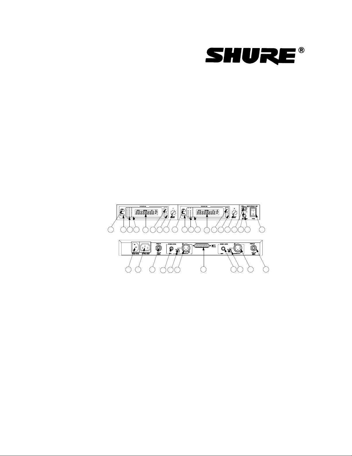
Controls and Connectors
1
4
5
23 6 8
13
14
7
15
16
1. MENU Button
2. SELECT Button
3. RF Level Indicators
4. AUDIO Level Indicators
5. Programmable Display
6. + Button
7. – Button
8. Volume Control
9. Headphone Monitor Volume Control
10. Headphone Monitor Status
Figure 1. U4D Receiver Controls and Connectors
Service Note: Shure recommends that all service procedures be performed by a Factory-Authorized
Service Center or that the product be returned directly to Shure Brothers Inc.
Licensing: Operation may require a user license. Frequency or power-output modifications may
violate this product’s approvals. Contact your country’s communications authorities.
1
18
17
23
4
6
5
7
8
91011
17 181619 15
12
11. Headphone Input Connector
12. POWER On/Off Switch
13. Power Input Connector
14. Power Output Connector
15. Antenna Input Connect ors
16. HIGH Z (Unbalanc ed) Out put Connec tor
17. Mic/Line Slide Switch
18. LOW Z (B alanced) Output Connect or
19. Networking Interface
E1999, Shure Incorporated Printed in U.S.A.
25D1062 (AG)

Circuit Description
Power Section
The receiver accepts power line voltage ranging from 85 Vac to 264
Vac. The receiver hardware uses the +5 Vdc, +12 Vdc and 12 Vdc voltages from the switching power supply. The switching power supply has
40 W overall output power capability, with maximum current capabilities
of 4A at 5V, 2A at +12V, and .5A at –12V. It also includes a fast–acting
2.5A fuse.
Up to four in-line rf amplifiers may be connected to the receiver,
depending on system setup. The receiver provides dc power to the inline amplifiers via the BNC antenna ports and RG58 cables. Maximum
dc power supplied to each antenna port is limited by self–resettable fuse.
Rf Section
The rf circuit description is limited to one rf strip (channel A) in
receiver 1. The other rf strip (channel B) is virtually identical. The local
oscillator (LO) section is common for both channels and is described
separately. Receiver 2 is identical to receiver 1.
Shure U4D Dual Diversity UHF Receiver
Rf Channel
The rf input signals are sent from the antenna ports to the receiver
via cables with BNC and rf mini–plug connect ors . Antenna port A is connected to J302 of receiver 1. Antenna port B is connected to J302 of
receiver 2. Connect or s J302 on each rec eiv er are the input of the rf
power dividers.
Each of these splits the rf power from the antenna between two
receivers. The outputs of the power div iders are connected to the inputs
of the opposite rf strips of the other receiver: J303 of receiver 1 to J304
of receiver 2; and J303 of receiver 2 to J304 of receiver 1. In addition,
J306 on receiver 1 and J306 on receiv er 2 have to be solder jumpered to
provide connection from the outputs of the rf power dividers to channel A
rf strips of both receivers.
The rf signal is preselected to the appropriate frequency range with
two dielectric filters. The first dielectric filter is located between the
antenna port and the low noise amplifier (LNA). The second filter is
located between the LNA block and mixer input. The front end down–
converter integrated circuit contains the LNA block and the first mixer.
The first conversion produces the first intermediate frequency (IF)
signal at 50 MHz. The first if signal is amplified with the MMIC, bandlimited with a SAW filter, then down-converted to the second IF frequency (10.7 MHz) with a second down-converter.
25D1062 (AG)
The second down-converter has an internal second local oscillator
(LO) t hat o sc illat es at 60.7 M Hz, using an ext ernal crystal. The second
LO buffered output also provides the LO drive to channel B of the sec-
2
Circuit Description

Local Oscillator
Shure U4D Dual Diversity UHF Receiver
ond mixer. The second down–converter also incorporates an internal IF
amplifier that is used with external 10.7 MHz ceramic filters. The 10.7
MHz signal goes to the second IF gain block with detector. The audio
output is buffered with an operational amplifier, then processed as described in the Audio section. The noise output is also amplified by the
operational amplifier, prov iding a signal for the noise squelch circuitry.
The received signal strength indication (RSSI) output of LM 1865 is used
to drive the LEDs on the receiver front panel.
The first loc al oscillat or (LO ) is common for channel A and channel B
rf strips. The LO is a phase locked-loop (PLL) syst em . The PLL consist s
of a pres caler / sy nt hes izer, volt age-c ont r olled oscillator (VCO ), loop filter,
rf power divider, and band-pass filt er, band limiting the LO signal before
injection to the first down convert er. The presc aler rec eives the rf signal
from the VCO via the coupling capacitor, C116. The output from the
phase detector is connec ted to the ext ernal loop filt er, which contr ols the
tuning voltage input to the VCO.
The prescaler / s y nt hes iz er integrated cir c uit (IC) is a serial programmable input IC. It receives the programming data from the front panel/
digital board. The digital board includes a user-controlled microprocessor
that allows us ers to change the fr equency and other sett ings.
Audio Section
The audio for channel A com es from the channel A detec t or output
of the rf sect ion. Each channel’s audio then ent ers its own fac t or y- adjus table gain amplifier stage. These adjustable gain st ages are used to
exactly matc h the audio levels coming from each rf channel, as well as to
set the proper level necessary for the compandor.
From the gain stages, eac h channel enters an analog switch. Noise
outputs also come from the channel A and channel B detector out put s .
Each noise output enters a bandpass noise filter that is used to measure
the 60 kHz noise present in the audio signal. The noise level is proportional to the signal-to-noise rat io of the channel.
The noise from a channel, af t er being rectified and low-pass filt er ed
(changed from an ac to dc signal), enters a bank of comparators. A version of the channel’s noise that is 6 dB less also enters the com parat or
bank. The noise levels fr om the two channels are then com par ed. If they
are within 6 dB of each other, the comparators send a logic high signal to
the control of each channel’s analog switch, and audio is allowed to pass
through the switc hes.
If the noise levels are not within 6 dB of each other, the channel with
the noise level greater than 6 dB of the other channel is not allowed to
pass through the analog switc h; the compar at or puts a logic low signal
on the contr ol line for the analog switch. Also, each channel ’s noise is
3 25D1062 (AG)Circuit Description

Shure U4D Dual Diversity UHF Receiver
compared to an adjustable squelch level (a dc level). If either channel’s
noise is greater than the squelch threshold, its switch is shut off.
The outputs from the analog switches are connected at the audio
combining stage. This is a unity gain buffer stage where the audio from
channel A is combined with the audio from channel B. The output from
this stage splits into three paths.
The first pat h goes to a high Q tone key detection circuit. This circuit
is a crystal filt er in which the tone key level is convert ed to dc and
compared to a fixed dc voltage. If the tone key is not pres ent , the
comparator sends a logic high signal to an audio mute IC and mutes
the receiver output. If the tone key is pres ent , a logic low signal is sent,
and the audio is allowed to pass.
The second path goes to a low Q bandpass filter centered around
32 kHz. This filter provides low battery detection in the receiver. The
lower Q allows for small frequency variation of tone key from various
transmitters, without large amplitude variations that the crystal filter
would have.
The filtered signal is then rectified and averaged. The resulting dc
signal is amplified and then enters the digital section of an analog to digital (A/D) converter. The A/D converter and the microcontroller
control the battery icon on the LCD display.
The third path goes into the compandor, via a 17 kHz low-pass filter.
Here the audio is expanded and de-emphasized. The compandor output
then goes off the audio board to a volume potentiometer on the front
panel board. Then the wiper is brought back to the audio board.
At this point, the audio signal takes two paths. The first path is
through the mute IC and into the output stage. The output stage consists
of an inverting amplifier stage, the output of which goes directly to one
pin of an XLR connector. A 180° phase-shifted version of the same signal is obtained by tapping off of this point and entering another inverting
stage. This phase-shifted version then goes to another pin on the XLR
connector.
Taking the output across the two XLR pins provides an electrically
balanced output signal. The unbalanced output is obtained by taking one
of the output stage amplifier’s outputs with respect to ground. Each side
of the balanced output goes through a pad that is switched in or out by
the user. This switch changes the balanced output level by approximately 30 dB.
25D1062 (AG)
The second path is through the headphone amplifier circuit. The
audio signal goes into a fixed gain amplifier, then off the board to the
monitor board. The monitor board can select between receiver 1 and
receiver 2. It also has a user-adjustable gain control, and a 1/4 inch jack
for headphones.
For the audio level meter, audio is tapped off from the 17 kHz filter
output and goes through a full wave precision rectifier and averaging circuit. This dc signal then enters a dc amplifier stage to adjust levels for
4
Circuit Description

Shure U4D Dual Diversity UHF Receiver
the LEDs. The output from this stage drives the audio level meter on the
front panel board.
A dc voltage from the detector chip RSSI drives the bar graph
integrated circuit on the front board for the rf level meters.
Display Board / Digital Section
Microcontroller Section
The microcont roller section consist s of microcont roller U103 and the
liquid crystal display (LCD). The microcontr oller has an on-board LCD
driver. R104, R116, and R118 supply the microcontroller wit h LCD drive
voltage for a four-plex drive. The LCD is a transmissive type that uses a
backlight for optimum readability. J104 supplies cur rent , limited through
5 Ω (paralleled R119 and R120), +5V for the LCD diffused backlight LED
array .
The LCD indicates frequency in MHz, a user-programmable name
up to 8 charact ers long, and the UHF frequenc y group, channel, and
television channel.
The LCD also has a battery fuel gauge that indicates the state of
the transmit t er bat t ery. A padlock icon on indicates whether the useraccessible menus are locked or unlocked. A 4.000 MHz osc illat or (Y 101)
provides the operating frequency to the microcont roller.
The oscillator circuit includes C107, C108, R111, R112, and Y101.
R105 and C103 form the reset circuit. R121 is the pull-up resistor for the
U103 programming voltage pin.
Memory Sect i o n
The memory consists of non-volatile ferroelectric RAM or EEPROM
U106, which stores current receiver settings and maps of compatible
groups and channels. R108 and R109 allow in-circuit programming of
U106 FRAM.
Analog to Digital Converter Section
The analog to digital converter section consists of A/D converter
U101. Signal DLOW_BATT (P102.2, U101.2, I138) from the audio section is an analog signal representing the transmitter’s battery level. This
is converted to an 8-bit digital signal for the microcontroller and is displayed on the LCD as the battery fuel gauge. Microcontroller U103
communicates serially with A/D converter U101.
5 25D1062 (AG)Circuit Description

Shure U4D Dual Diversity UHF Receiver
User Interface Section
The user interface section consists of switches SW101 MENU,
SW103 SELECT, SW102 UP (+), and SW104 DOWN (–). These
switches provide access to various user-programmable menus on the
front panel display. The LCD provides the user with feedback for all
switch actions performed.
Audio Output Level Control R110
The audio output level control potentiometer has no associated
circuitry in this section. Refer to the Audio Section.
RSSI Bar Graph Section
Channel A
Bar graph driver U104 gets the DRSSI_CH_A analog signal (U104.5,
P102.6, I155) from the rf-audio board and indicates its strength on the
5-LED bar graph formed by D117, D115, D110, D109, and D105.
Channel B
Bar graph driver U102 gets the DRSSI_CH_B analog signal (U102.5,
P102.11, I170) from the rf-audio board and indicates its strength on the
5-LED bar graph formed by D116, D114, D111, D108, and D106.
Audiometer Bar Graph Section
Bar graph driver U105 gets the DAUDMTR audio metering (averaging only, no peak) signal (U105.5, P102.13, I156) from the rf-audio board
and indicates its strength on the 7-LED bar graph formed by D119, D118,
D113, D112, D107, D104, and D103.
Diversity LEDs D101 and D102
Diversity LEDs A and B have no associated circuitry in this section.
Refer to the Audio Section.
Digital to Analog Converter Section
The microcontroller communicates with 8-bit serial D/A converter
U215 over two signal wires, DSQUELCH (P102.3, U103.10, TP113) and
DSCL (P102.15, U103.9, T114), to set up the audio squelch threshold.
25D1062 (AG)
6
Circuit Description
Shure U4D Dual Diversity UHF Receiver
Display Board Interconnect with Rf-Audio Board
Integrated ribbon cable connector P102 interfaces with the rf-audio
board and the networking Interface board through the display board. Pin
assignments for the P102 connector are presented in the table below.
Table 1
P102 Interconnect Pin Assignments
PIN NO. SIGNAL NAME DESCRIPTION
1 D+5V +5V power supply to the Digital Board
2 DLOW_BATT Analog voltage representing TX battery level
3 DSQUELCH Data signal to U215 squelch D/A
4 GND Input power ground to the Digital Board
5 DLE Data Load Enable to U309 PLL Synthesizer
6 DRSSI_CH_A Chan. A rf Received Signal Strength Indicator
7 DD Data signal to U309 PLL Synthesizer
8 DLEDA Diversity LED A drive signal input
9 DCK Clock signal to U309 PLL Synthesizer
10 DLEDRET Diversity LED A and B common return
11 DRSSI_CH_B Chan. B rf Received Signal Strength Indicator
12 DLEdB Diversity LED B drive signal input
13 DAUDMTR Audio metering analog signal input
14 N141 Audio potentiometer return to the Audio Board
15 DSCL Clock signal to U215 squelch D/A
16 N142 Audio potentiometer wiper to the Audio Board
17 DLONE_W_OUT Interrupt output to the Networking Interface
18 N143 Audio potentiometer input from the Audio Board
19 DSDO Networking Serial Data Output
20 DLONE_W_INT Interrupt input from the Networking Interface
7 25D1062 (AG)Circuit Description

Notes
Shure U4D Dual Diversity UHF Receiver
25D1062 (AG)
This page intentionally left blank.
8
Notes
Preliminary Tests
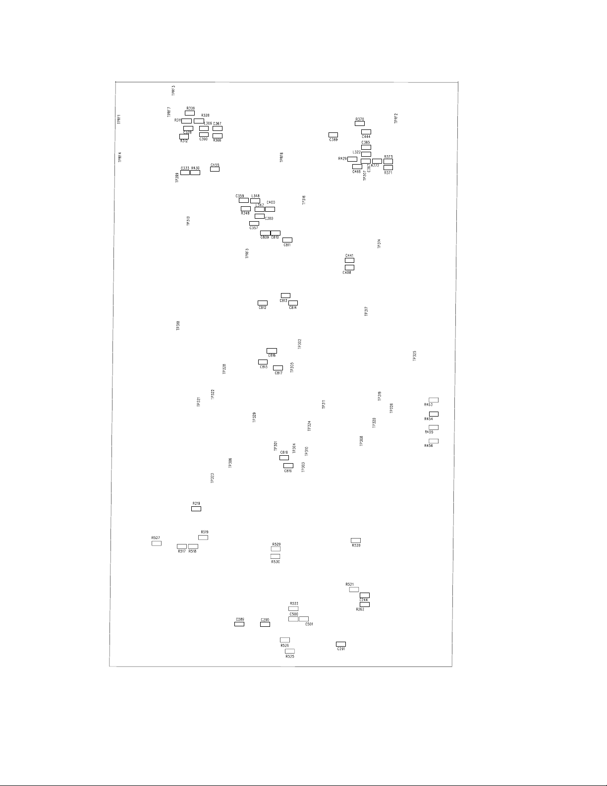
Test Component Locations
Shure U4D Dual Diversity UHF Receiver
Rf-Audio Board, Side 1
9 25D1062 (AG)Preliminary Tests
Shure U4D Dual Diversity UHF Receiver
25D1062 (AG)
10
Audio-Rf Board, Side 2
Preliminary Tests

Listening Test
whether it is functioning normally and try duplicating the reported malfunction. Ref er to the User Guide for operat ing instructions, troubleshooting
suggestions, and specif icat ions .
on any reported problem. The following, more extensive, functional tests
require partial disassembly.
Functional Tests
for the following func tional tests.
components in the power supply partition of the receiver. The heat
sink of the switching power supply and all ac wiring contain hazardous
voltages.
Shure U4D Dual Diversity UHF Receiver
Before completely disassembling the receiver, operate it to determine
Review any customer complaint or request, and focus the listening test
Refer to the Disassembly section to partially disassemble the receiver
Use dc blocks at all rf out put to protect test equipment.
To reduce the risk of electrical shock, do not touch or short any
1. Remove five screws and washers from the top of the receiver
and two screws and washers from the left and right sides of the
receiver. Lift off the top cover.
2. Program the receiver squelch through the SET SQCH menu
to –10.0.
3. Program the receiver frequency through the SET FREQ menu to
any clean frequency in your area. To do this, select an inactive
television channel and then scan for a frequency at which the
yellow LEDs (RF A/RF B) are not lit. Note this frequency as Fo .
4. Connect a dc voltmeter to the center conductor (+) and the
ground (–) of BNC antenna channel A input, marked ANTENNA
A IN. The measured voltage should be to be ± 12.0 0.5 Vdc.
5. Set the rf signal generator frequency to Fo. Set the Level to
–90 dBm and set the deviation as follows:
UA, UB, MA, MB, MC, MD: 45 kHz deviation at 1 kHz modulation
KK: 40 kHz deviation at 1 kHz modulation
II: 28 kHz deviation at 1 kHz modulation
6. Connect the rf signal generator to the BNC antenna channel
A input, marked ANTENNA A IN. Be sure to use a dc block to
protect the test equipment.
7. Rotat e the receiver Out put Level control to a fully clockwise
position.
11 25D1062 (AG)Preliminary Tests

Shure U4D Dual Diversity UHF Receiver
8. Make sure the tone key switch (S201) on the receiver rf-audio
board is in the ON position.The receiver should be muted. No
audio output should be present at the balanced and unbalanced
outputs.
9. Slide the tone key switch to the OFF position. J211 can be
accessed from the outside of the receiver and is marked
BALANCED LOW Z. With the audio analyzer in the Float
position, the audio voltage at balanced audio output J211 with
the switch at the LINE position (pin 2 and 3, unloaded) should
be as follows:
UA, UB M A, MB, MC, MD:
2.5 ± 0.5 Vrms
KK: Not available at this time;
measurements will be available later.
II:
1.7 ± 0.5 Vrms
10. J209 can be accessed from the outside of the receiver and is
marked HIGH Z. With the audio analyzer NOT in the Float
position, the audio voltage at unbalanced audio output J209
(pin 1 and 2, unloaded) should be as follows:
UA, UB,MA, MB, MC, MD:
1.25 ± 0.25 Vrms
KK: Not available at this time;
measurements will be available later.
II:
0.837 ± 0.25 Vrms
11. Set the rf signal generator Level to –105 dBm. The receiver
should be muted. No audio output should be present.
12. Connect a dc voltmeter to the center conductor (+) and the
ground (–) of receiver BNC antenna channel B input, marked
ANTENNA B IN. The measured voltage should be 12.0 ±
0.5 Vdc.
13. Set the rf signal generator Level to –90 dBm, and connect it to
the receiver BNC antenna channel B input, marked ANTENNA
B IN. Be sure to use a dc block to protect the test equipment.
25D1062 (AG)
14. Repeat steps 7 through 11.
15. Return the tone key switch (S201) to the ON position.
16. Repeat the procedure on the second receiver.
12
Preliminary Tests
Shure U4D Dual Diversity UHF Receiver
Disassembly and Assembly
! IMPORTANT SAFETY INSTRUCTIONS !
1.. READ these in s t r u c t i o n s .
2.. KEEP these instructions.
3.. HEED all warnings.
4.. FOLLOW all instructions.
5.. DO NOT use this apparatus near water.
6.. CLEAN ONL Y with a damp cloth.
7.. DO NOT block any of the ventilation openings.
Install in accordance with the manufacturer’s
instructions.
8.. DO NOT defeat the safety purpose of the grounding-type plug. The third prong is provided for
your safety. When the provided plug does not fit
into your outlet, consult an electrician for
replacement of the obsolete outlet.
9.. PROTECT the power cord from being walked on
or pinched, particularly at plugs, convenience
receptacles, and the point of exit from the
apparatus.
10.. USE only attachments/accessories specified by
the manufacturer.
11.. USE only with a cart, stand, tripod, bracket, or
table specified by the manufacturer or sold with
the apparatus. When a cart is used, use caution
when moving the cart-apparatus combination to
avoid injury from tip-over.
12.. UNPLUG this apparatus during lightning storms
or when unused for long periods of time.
13.. REFER all servicing to qualified service personnel. Servicing is required when the apparatus has
been damaged in any way, such as when the power-supply cord or plug has been damaged, liquid
has been spilled or objects have fallen into the apparatus, t h e apparatus has been exposed to rain
or moisture, does not operate normally, or has
been dropped.
! CAUTION !
Observe precautions when handling this static-sensitive device.
! WARNING !
Voltages in this equipment are hazardous to life. No user-serviceable parts are inside.
Refer all servicing to qualified service personnel. The safety certifications of the U4D Dual Diversity Receiver
do not apply when the operating voltage is changed from the factory setting.
To reduce the risk of electrical shock, do not touch or short any components
in the power supply partition of the receiver. The heat sink of the switching
power supply and all ac wiring contain hazardous voltages.
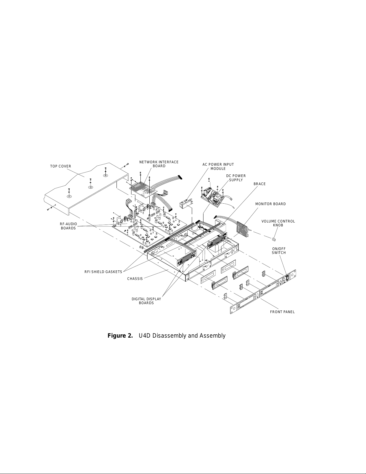
Top Cover Removal
1. Remove five screws and washers from the top of the receiver.
2. Remove two screws and washers from the left and right sides
of the receiver.
3. Slide the top cover off of the receiver to expose the circuit
boards.
13 25D1062 (AG)Disassembly and Assembly
Front Panel Removal
1. Remove the three screws securing the brace and the rf shielding
gaskets to the chassis, then remove the brace.
2. Remove the hexnuts and star washers securing the front panel
to the inside of the front chassis.
3. Tag and disconnect the power on/off switch from the power
supply wires.
4. Remove the rubber monitor volume control knob and the master
volume control knob by pulling them away from the front panel.
5. Carefully pull the front panel away from the chassis.
Shure U4D Dual Diversity UHF Receiver
TOP COVER
RF-AUDIO
BOARDS
RFI SHIELD GASKETS
NETWORK INTERFACE
CHASSIS
DIGITAL DISPLAY
BOARDS
BOARD
AC POWER INPUT
MODULE
DC POWER
SUPPLY
BRACE
MONITOR BOARD
VOLUME CONTROL
KNOB
ON/OFF
SWITCH
FRONT PANEL
25D1062 (AG)
Figure 2. U4D Disassembly and Assembly
14
Disassembly and Assembly

Shure U4D Dual Diversity UHF Receiver
Printed Circuit Board (PCB) Removal
Rf-Audio Board Removal
1. Tag and disconnect the cables attached to the pcbs. Standard
cable connections are shown in Figure 3.
2. Remove the scr ews and washer s that secure the rf- audio pcb
to the receiver chassis, then lift the board out.
Display Board Removal
1. Remove the rf shield brace inside the receiver by removing
the three screws and washers securing it to the bottom of the
chassis.
2. Remove each display pcb by removing the two screws securing
the board to the back of the front chassis. Then pull the board
away from the chassis and lift the board out.
Monitor Board Removal
1. Perform the following steps after removing the front panel.
2. Remove the hexnuts that secure the stem of the monitor volume
control and the monitor output connector to the front chassis.
3. Pull the monitor board away from the chassis.
Power Supply Removal
1. Tag and disconnect the cables attached to the power supply.
2. Remove the screws and washers that secure the power supply to
the receiver chassis, then lift the power supply out.
U4D Assembly
1. Reinstall the rf–audio circuit boards and secure them with the
previously removed screws and washers.
2. Reinstall the power supply and secure it with the previously
removed screws and washers.
3. Reinstall the display pcbs and secure them with the previously
removed hexnuts and washers.
4. Reinstall the monitor circuit board and secure it to the chassis by
reinstalling the previously removed hexnuts and washers over
the volume control pot and output connector.
5. Reinstall the front panel and secure it to the front chassis with
the previously removed hexnuts and washers.
6. Reinstall the steel brace and secure it with the previously
removed screws and washers.
7. Reconnect all tagged wires and cables. Standard cable
connections are shown in Figure 3.
8. Reinstall the top cover, and secure it with the previously
removed screws and washers.
15 25D1062 (AG)Disassembly and Assembly

ANTENNA A
TO MONITOR
RECEIVER 1
BOARD
TO NET
BOARD
J216
J203
TO DISPLAY
BOARD
NETWORK
INTERFACE BOX
NETWORK
BOARD
TO MONITOR
BOARD
Shure U4D Dual Diversity UHF Receiver
RECEIVER 2
J203
TO NET
BOARD
TO DISPLAY
BOARD
ANTENNA B
J216
AC POWER
INPUT
DC POWER
SUPPLY
J301
J302
DUAL: BNC REAR
RF-AUDIO
BOARD
J303
DUAL: RF/LO
DUAL: RF/LO
J304
DUAL: BNC REAR
RF-AUDIO
BOARD
SINGLE: BNC REAR
J301
J302
J303
DUAL: RF/LO
DISPLAY BOARD DISPLAY BOARD
Figure 3. Final Cable Configuration
DUAL: RF/LO
J30
4
BOARD
MONITOR
POWER
ON/OFF
SWITCH
25D1062 (AG)
16
Disassembly and Assembly

Shure U4D Dual Diversity UHF Receiver
Service Procedures
Product Changes
The following changes have been made to the U4D receiver.
New Volume Control Knobs and Potentiometers
The new potentiometers cannot be used on old boards, and the new
knob assembly cannot be used with old potentiometers.
PRINTED CIRCUIT
BOARD REVISION
“G” or earlier 46A8048 90A8652
“H” or later 46A8069 90A8747
R110 VOLUME CONTROL
POTENTIOMETER PART NO.
VOLUME CONTROL KNOB
ASSEMBLY PART NO.
New Digital Display Board Pushbutton Actuators
The old actuators cannot be used on newer display boards. If for
any reason the display board is replaced, the actuators must also be
updated. However, any revision display board can be mixed with any
revision rf–audio board. On newer boards, the switches will be surface
mount components; on older boards the switches are thru-hole
components.
PRINTED CIRCUIT
BOARD REVISION
“J” or earlier 66A8039 55A187 (thru-hole)
“K” or later 66A8044, 66A8045 155A03 (SMT)
RUBBER ACTUATOR
P ART NO.
PUSHBUTTON SWITCH
P ART NO.
New PCB layout, component changes and designations
The U4 receiver PCB layout (34A8507K and earlier) has been
revised due to discontinued status to part number 188A190 (FM IF/Quad
detector). The new replacement component 188A129 (FM IF/Quad
detector) is not pin for pin compatible so, associated support circuitry
was added which results in the new PCB layout (34A8703). Also a new
choice of RF front end filters were chosen which contributed to the new
PCB layout change
PRINTED CIRCUIT
BOARD REVISION
34A8507K or earlier U303 and U313 L304 and L310
34A8703 U315 and U316 FL311 and FL313
17 25D1062 (AG)Service Procedures
FM IF / QUAD
DETECTOR
QUADRATURE
COIL

Test Equipment
Service Equipment Manual. The following test equipment (or approved
equivalent) is also needed.
Shure U4D Dual Diversity UHF Receiver
Most test equipment needed is described in the Shure Wireless
Table 2
Test Equipment
Equipment Type Model
Audio analyzer *Hewlett-Packard 8903B
Digital multimeter Fluke 87
Rf signal generator HP 8656B or E440B
Frequency counter Hewlett-Packard 53181A
Spectrum analyzer HP 8590L or E4403B
Shure U4D receiver Shure U4D
*Audio levels in dBu are marked as dBm on the HP8903B.
LCD Back Light
Brightness Adjustment
Adjust R531 on the display board to achieve desired brightness
level.
This adjustment is only possible on G and later versions of the
printed circuit board.
25D1062 (AG)
18
Service Procedures

Alignment
Test Setup
Shure U4D Dual Diversity UHF Receiver
Align Receivers 1 and 2 separately. Receiver 1 is on the left and
Receiver 2 is on the right when looking at the front panel.
Equipment setup for the alignment procedure is sequential.
1. Remove the top cover from the U4D receiver.
2. To reduce the risk of elect r ical shock, do not touch or short any
components in the receiver switching power supply. The heat
sink on the power supply and all ac wiring cont ains hazardous
voltages.
3. Dc voltages are present at most rf test points. Use dc blocks on
the rf signal generator to protect the test equipment.
SOLDER JUMPER
4. Use RG58 or any other low loss 50 Ω cables for all rf connections. Keep test cables as short as possible. Include insertion
loss of cables and connectors when making rf measurements.
5. Remove the network board.
RECEIVER 1 RECEIVER 2
S201
J306
S201
SOLDER JUMPER
J306
Figure 4. U4D Receiver Solder Jumper Locations
19 25D1062 (AG)Service Procedures

Alignment
Shure U4D Dual Diversity UHF Receiver
1. Turn the U4D receiver power ON.
2. Connect the U4D receiver antennas.
3. Program the U4D receiver to any clean frequency in the area,
using the SET FREQ menu on the display. To do this, select a
television channel that is inactive in the area, and then scan for
a frequency at which the yellow rf LEDs are not lit. Note this
frequency as Fo.
4. Remove the U4D receiver antennas.
5. Connect the audio analyzer output to the external (EXT)
modulation input of the rf signal generator.
6. Set the audio analyzer output for 1 kHz and 1.4 V (5.2 dBu).
7. Adjust the audio analyzer output amplitude until both the HI EXT
and LO EXT lights on the rf generator turn off (use amplitude
increments of 10 to 100 mV).
8. Make sure all internal tone generators on the rf signal generator
are turned off. Set the rf signal generator deviation as follows:
UA, UB,MA, MB, MC, MD: 45 kHz deviation at 1 kHz modulation
KK: 40 kHz deviation at 1 kHz modulation
II: 28 kHz deviation at 1 kHz modulation
9. Turn ON the 400 Hz high-pass and 30 kHz low-pass filters on
the audio analyzer.
10. Verify that solder jumpers J306 are closed.
11. Set the receiver squelch control to the mid-level (0) position.
12 . Slide tone key switch (S 201) on the rf–audio board to the
OFF pos ition.
25D1062 (AG)
20
Service Procedures

Rf Tuning, Channel A
Dc Voltage Verification
Shure U4D Dual Diversity UHF Receiver
DC VOLTMETER
ANTENNA A IN
S201
(OFF)
P203
P202
C242
C227
P202
S201
(OFF)
P203
ANTENNA B IN
P202
DC VOLTMETER
P202
J302
Figure 5. Dc Voltage Level Verification
1. Measure the dc voltage between the center pin of BNC
connector ANTENNA A IN, located on the receiver rear panel,
and ground. The voltage should measure 12.0 ± 0.5 Vdc.
2. Measure the dc voltage between the center pin of BNC
connector ANTENNA B IN, located on the receiver rear panel
and ground. The voltage should measure 12.0 ± 0.5 Vdc.
21 25D1062 (AG)Service Procedures

Shure U4D Dual Diversity UHF Receiver
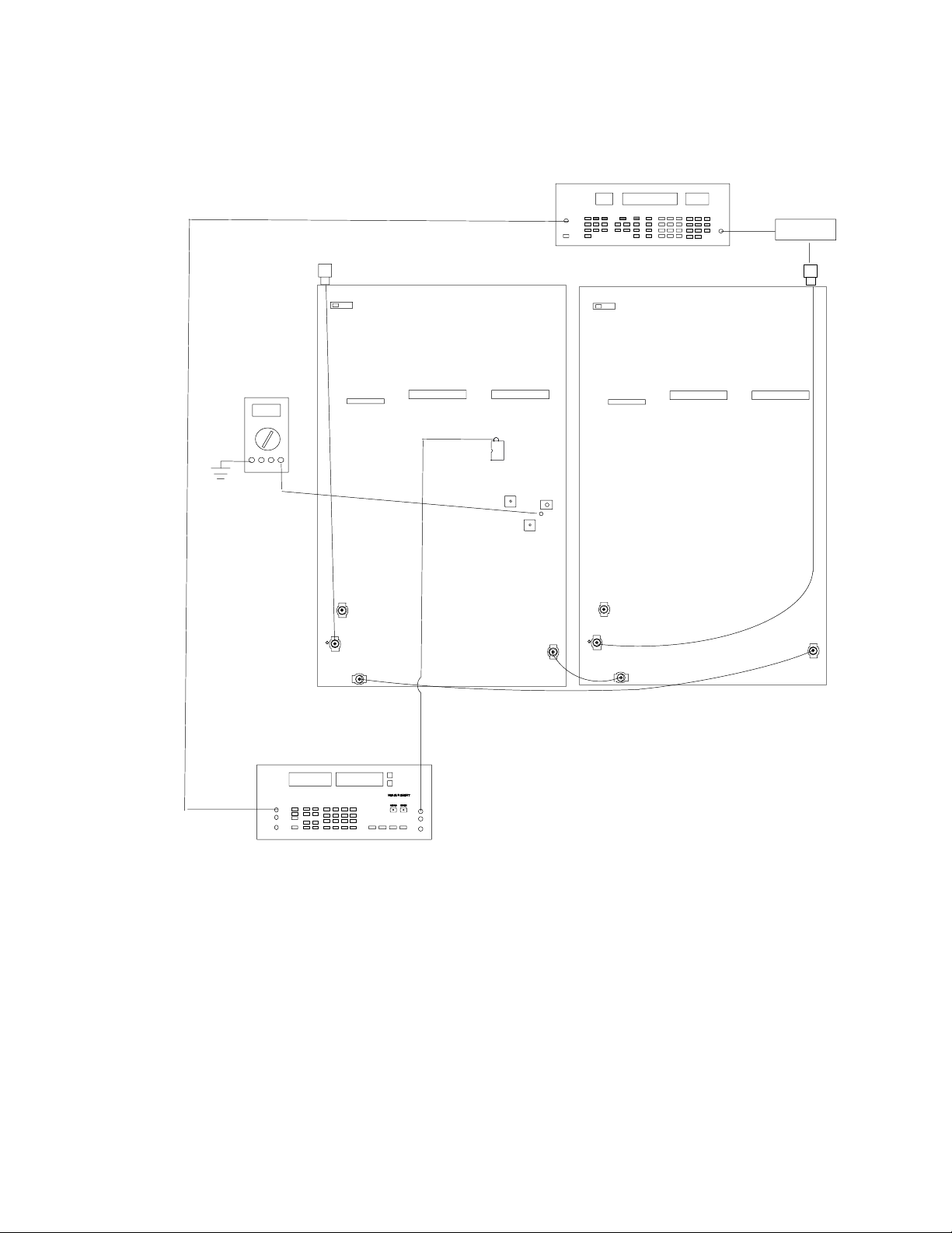
Local Oscillator Frequency Alignment (Channel A)
ANTENNA A IN
S201
(OFF)
P203
VC101
TPRF6
J302
P202
PIN 1
U308
VCO
P202
S201
(OFF)
P203
ANTENNA B IN
P202
P202
FREQUENCY COUNTER
Figure 6. Local Oscillator Frequency Alignment
If using a spectrum analyzer, adjust the span so that the frequency
accuracy measurement is better than1 kHz.
1. Attach a spectrum analyzer or frequency counter to TPRF6
(pin 1 of the U308 VCO).
2. Adjust VC101 for (Fo + 50 MHz) ± 5.0 kHz.
3. Disc onnect the spectr um analyzer or the frequenc y counter from
TPRF6.
CH 2
CH 1
25D1062 (AG)
22
Service Procedures

Shure U4D Dual Diversity UHF Receiver
FM Detector Quadrature Coil Alignment (Channel A)
RF SIGNAL GENERATOR
NOTE: DC VOLTAGES ARE PRESENT
AT MOST RF TEST POINTS. USE A DC
BLOCK ON THE RF SIGNAL GENERATOR
TO PROTECT TEST EQUIPMENT.
DC BLOCK
AUDIO ANALYZER
ANTENNA A IN
S201
(OFF) (OFF)
TP306
P202
U305
P202
P203
L310 for PCB 34A8507
FL311 for PCB 34A8703
J302
P203
ANTENNA B IN
S201
P202P202
Figure 7. FM Detector Quadrature Coil Alignment Connections
1. Set the rf signal generator Frequency to Fo. Set the Level to
–86 dBm and verify the Deviation as follows:
UA, UB,MA, MB, MC, MD: 45 kHz deviation at 1 kHz modulation
KK: 40 kHz deviation at 1 kHz modulation
II: 28 kHz deviation at 1 kHz modulation
2. Connect the rf signal generator to the ANTENNA A input.
3. Connect the audio analyzer to U305, pin 7 (TP306).
4. Make sure that audio analyzer 400 Hz high-pass filter and
the 30 kHz low-pass filter are activated.
5. For PCB version 34A8507 tune L310 for maximum audio output
at TP306. For PCB version 34A8703 tune FL311 for maximum
audio output at TP306. The low limit is 250 mVrms. There is no
high limit.
23 25D1062 (AG)Service Procedures

Shure U4D Dual Diversity UHF Receiver
Second Mixer Coil Alignment (Channel A)
RF SIGNAL GENERATOR
NOTE: DC VOLTAGES ARE PRESENT
AT MOST RF TEST POINTS. USE A DC
BLOCK ON THE RF SIGNAL GENERATOR
TO PROTECT TEST EQUIPMENT.
DC BLOCK
DC VOLTMETER
ANTENNA A IN
S201
(OFF)
P203
U303 / U315
PIN 8 / PIN 17
J302
L313
ANTENNA B IN
S201
(OFF)
P202P202
P203
P202
P202
25D1062 (AG)
Figure 8. Channel A Second Mixer Coil Alignment
1. Change the rf input level to –105 dBm.
2. Adjust L313 for maximum dc voltage at U303 pin 8 for PCB version 34A8507 or at U315 pin 17 for PCB version 34A8703.
24
Service Procedures

Shure U4D Dual Diversity UHF Receiver
THD Verification and RSSI Adjustment (Channel A)
RF SIGNAL GENERATOR
NOTE: DC VOLTAGES ARE PRESENT
AT MOST RF TEST POINTS. USE A DC
BLOCK ON THE RF SIGNAL GENERATOR
TO PROTECT TEST EQUIPMENT.
DC BLOCK
AUDIO ANALYZER
DC VOLTMETER
ANTENNA A IN
S201
(OFF)
P203
TP306 AUDIO CH A
L310 for PCB 34A8507
R355
TP328 RSSI CH A
L311 for PCB 34A8703
J302
ANTENNA B IN
S201
(OFF)
P202P202
P203
P202
P202
Figure 9. Channel A RSSI Alignment
1. Change the rf signal generator Level to –50 dBm.
2. Measure the total harmonic distortion (THD) at TP306
(U305 pin 7). It should be less than 0.5%. If not adjust L310 for
PCB version 34A8507 or adjust FL311 for PCB version 34A8703
to minimize the distortion.
3. Adjust R355 for Vrssi at the wiper (TP328). The Vrssi should be
2.75 ± 0.1 Vdc for 34A8507F and earlier PCB versions.The Vrssi
should be 2.3 ± 0.1 Vdc for 34A8507G and later versions of the
board and the 34A8703 PCB version.
25 25D1062 (AG)Service Procedures

Noise Set-Up (Channel A)
The Noise Setup procedure aligns each channel so that for a given
signal-to-noise ratio, the respective dc levels match.
RF SIGNAL GENERATOR
DC BLOCK
Shure U4D Dual Diversity UHF Receiver
NOTE: DC VOLTAGES ARE PRESENT
AT MOST RF TEST POINTS. USE A DC
BLOCK ON THE RF SIGNAL GENERATOR
DC VOLTMETER
TO PROTECT TEST EQUIPMENT.
ANTENNA A IN
S201
(OFF)
C242
C227
P203
J302
P202
R264
P202
P203
ANTENNA B IN
S201
(OFF)
P202P202
Figure 10. Channel A Noise Setup Connections
1. Set the modulating frequency from the audio analyzer to 60 kHz
and, if necessary, readjust the amplitude so HI EXT and LO EXT
lights turn off. Use amplitude increments of 10 to 100 mV.
25D1062 (AG)
2. Verify that the rf signal generator power is –61 dBm.
3. Place the (+) terminal of a dc voltmeter on the (+) side of C227
and connect the (–) terminal to ground.
4. For 34A8507F or earlier PCB versions, adjust R337 (not shown
above) until the voltmeter reads 8.00 ± 0.03 Vdc. For 34A8507G
or later PCB versions and PCB 34A8703, adjust R264 to 4.00 ±
0.03 Vdc.
26
Service Procedures

Shure U4D Dual Diversity UHF Receiver
FM Detector Quadrature Coil Alignment (Channel B)
RF SIGNAL GENERATOR
DC BLOCK
ANTENNA A IN
P203
J302
AUDIO ANALYZER
S201
(OFF)
P202
L304 for PCB 34A8507
P202
TP308
FL313
for PCB
34A8703
U310
ANTENNA B IN
S201
(OFF)
P203
NOTE: DC VOLTAGES ARE PRESENT
AT MOST RF TEST POINTS. USE A DC
BLOCK ON THE RF SIGNAL GENERATOR
TO PROTECT TEST EQUIPMENT.
P202
P202
Figure 11. Channel B FM Det ect or Quadrature Coil Alignment
1. Set the rf signal generator Level to –86 dBm and the Deviation
as follows. If necessary, readjust the amplitude so HI EXT and
LO EXT lights turn off.
UA, UB,MA, MB, MC, MD: 45 kHz deviation at 1 kHz modulation
KK: 40 kHz deviation at 1 kHz modulation
II: 28 kHz deviation at 1 kHz modulation
2. Connect the rf signal generator to the ANTENNA B input.
3. Connect the audio analyzer to U310, pin 7 (TP308).
4. For PCB version 34A8507 tune L304 for maximum audio output
at TP308.For PCB version 34A8703 tune FL313 for maximum
audio output at TP308. The low limit is 250 mVrms. There is no
high limit.
27 25D1062 (AG)Service Procedures

Shure U4D Dual Diversity UHF Receiver
Second Mixer Coil Adjustment (Channel B)
DC VOLTMETER
NOTE: DC VOLTAGES ARE PRESENT
AT MOST RF TEST POINTS. USE A DC
BLOCK ON THE RF SIGNAL GENERATOR
TO PROTECT TEST EQUIPMENT.
ANTENNA A IN
S201
(OFF) (OFF)
P203
P202
PIN 8 / PIN 17
P202
U313 / U316
RF SIGNAL GENERATOR
L324
P203
DC BLOCK
ANTENNA B IN
S201
P202P202
J302
Figure 12. Channel B Second Mixer Coil Adjustment Connections
1. Change the rf input level to –105 dBm.
2. Adjust L324 for maximum dc voltage at U313 pin 8 for PCB
version 34A8507 or at U316 pin 17 for PCB version 34A8703.
25D1062 (AG)
28
Service Procedures
Shure U4D Dual Diversity UHF Receiver
THD Verification and RSSI Adjustment (Channel B)
RF SIGNAL GENERATOR
ANTENNA A IN ANTENNA B IN
DC BLOCK
DC VOLTMETER
AUDIO ANALYZER
(OFF)
P203
J302
S201
P202
P202
TP308
U310
L304 for PCB
34A8507
FL313 for PCB
34A8703
R367
TP325
S201
(OFF)
P203
NOTE: DC VOLTAGES ARE PRESENT
AT MOST RF TEST POINTS. USE A DC
BLOCK ON THE RF SIGNAL GENERATOR
TO PROTECT TEST EQUIPMENT.
P202
P202
Figure 13. Channel B RSSI Alignment Connections
1. Change the rf signal generator level to –50 dBm.
2. Measure the total harmonic distortion (THD) at TP308
(U310 pin 7) should be less than 0.5%. If not adjust L304 for
PCB version 34A8507 or adjust FL313 for PCB version 34A8703
to minimize the distortion.
3. Adjust R367 for Vrssi at the wiper (TP325). The Vrssi should be
2.75 ± 0.1 Vdc for 34A8507F and earlier PCB versions.The Vrssi
should be 2.3 ± 0.1 Vdc for 34A8507G and later versions of the
board and the 34A8703 PCB version.
29 25D1062 (AG)Service Procedures

Noise Setup (Channel B)
The Noise Setup procedure aligns each Channel so that for a given
signal-to-noise ratio, the respective dc levels match.
Shure U4D Dual Diversity UHF Receiver
NOTE: DC VOLTAGES ARE PRESENT
AT MOST RF TEST POINTS. USE A DC
BLOCK ON THE RF SIGNAL GENERATOR
TO PROTECT TEST EQUIPMENT.
ANTENNA A IN
S201
(OFF) (OFF)
P203
DC VOLTMETER
C242
C239
U211
U203
P202
U202
P202
R265
RF SIGNAL GENERATOR
ANTENNA B IN
S201
P203
P202
DC BLOCK
P202
25D1062 (AG)
J302
Figure 14. Channel B, Noise Setup Connections
1. Set the modulating frequency from the audio analyzer to 60 kHz
and, if necessary, readjust the amplitude so HI EXT and LO EXT
lights turn off.
2. Verify that the rf signal generator output power is –61 dBm.
3. Place the (+) terminal of a dc voltmeter on the (+) side of C242
and connect the (–) terminal to ground.
4. For 34A8507F or earlier PCB versions, adjust R389 (not shown
above) until the voltmeter reads 8.00 ± 0.03 Vdc. For 34A8507G
or later PCB versions and PCB 34A8703, adjust R265 to 4.00 ±
0.03 Vdc.
30
Service Procedures

Audio Level Setup, Channel B
ANTENNA A IN
Shure U4D Dual Diversity UHF Receiver
RF SIGNAL GENERATOR
DC BLOCK
ANTENNA B IN
AUDIO ANALYZER
NOTE: DC VOLTAGES ARE PRESENT
AT MOST RF TEST POINTS. USE A DC
BLOCK ON THE RF SIGNAL GENERATOR
TO PROTECT TEST EQUIPMENT.
Figure 15. Channel B Audio Level Setup Connections
For the following test, make sure the tone key switch (S201) is OFF.
All Models (Except II and KK Models)
P203
J302
S201
(OFF)
U207
PIN 7
P202
R250
P202
P203
S201
(OFF)
P202
P202
1. Change the modulating frequency out of the audio analyzer to
1 kHz with deviation set to 45 kHz. If necessary, readjust the
amplitude so that the HI EXT and LO EXT lights turn off.
2. Place the (+) terminal of the audio analyzer on U207, pin 7, and
connect the (–) terminal to ground.
3. Adjust R250 until the audio analyzer reads 0.436 ± 0.005 Vrms.
II Models (Japan)
1. Set the rf signal generator’s deviation to 28.0 kHz and the
modulating frequency to 1 kHz.
2. Place the (+) terminal of the audio analyzer on U207, pin 7, and
connect the (–) terminal to ground.
3. Adjust R250 until the audio analyzer reads 0.282 ±. 003 Vrms.
KK Models (United Kingdom)
1. Set the rf signal generator’s deviation to 40.0 kHz and the
modulating frequency to 1 kHz.
2. Place the (+) terminal of the audio analyzer on U207, pin 7, and
connect the (–) terminal to ground.
3. Adjust R250 until the audio analyzer reads 0.436 ±. 003 Vrms.
31 25D1062 (AG)Service Procedures

Audio Level Setup, Channel A
Shure U4D Dual Diversity UHF Receiver
RF SIGNAL GENERATOR
AUDIO ANALYZER
NOTE: DC VOLTAGES ARE PRESENT
AT MOST RF TEST POINTS. USE A DC
BLOCK ON THE RF SIGNAL GENERATOR
TO PROTECT TEST EQUIPMENT.
For the following test, make sure the tone key switch (S201) is OFF.
DC BLOCK
ANTENNA A IN
S201
(OFF) (OFF)
P203
J302
U207
PIN 7
P202
R203
P202
P203
ANTENNA B IN
S201
P202
P202
Figure 16. Channel A Audio Level Setup Connections
All Models (Except II and KK Models)
1. Set the rf signal generator deviation to 45 kHz and modulating
frequency to 1 kHz.
2. Connect the rf signal generator to BNC connector ANTENNA A
IN on the receiver back panel.
3. Place the (+) terminal of the audio analyzer on U207, pin 7, and
connect the (–) terminal to ground.
4. Adjust R203 until the audio analyzer reads 0.436 ± 0.005 Vrms.
5. Disconnect the rf signal generator from the BNC connector
ANTENNA A IN on the receiver back panel.
II Models (Japan)
1. Set the rf signal generator deviation to 28 kHz and modulating
frequency to 1 kHz.
2. Connect the rf signal generator to BNC connector ANTENNA A
IN on the receiver back panel.
3. Place the (+) terminal of the audio analyzer on U207, pin 7, and
connect the (–) terminal to ground.
4. Adjust R203 until the audio analyzer reads 0.282 ±. 003 V.
5. Disconnect the rf signal generator from the BNC connector
ANTENNA A IN on the receiver back panel.
KK Models (United Kingdom)
1. Set the rf signal generator’s deviation to 40.0 kHz and modulating frequency to 1 kHz.
2. Connect the rf signal generator to BNC connector ANTENNA A
IN on the receiver back panel.
3. Place the (+) terminal of the audio analyzer on U207, pin 7, and
connect the (–) terminal to ground.
4. Adjust R203 until the audio analyzer reads 0.436 ±. 003 V.
5. Disconnect the rf signal generator from the BNC connector
ANTENNA A IN on the receiver back panel.
25D1062 (AG)
32
Service Procedures

Tone Key Filter Alignment
Reinstall the antennas for the Tone Key Filter Alignment procedure.
Shure U4D Dual Diversity UHF Receiver
DC VOLTMETER
ANTENNA A IN
S201
(ON)
PIN 8
U208
P203
J302
VC102
P202
P202
S201
(ON)
P203
P202
ANTENNA B IN
P202
Figure 17. Tone Key Filter Alignment Connections
For the following test, make sure the tone key switch (S201) is ON.
1. Turn the tone key switch (S201) to the ON position.
2. Turn the rf signal generator output OFF.
3. Be sure to reinstall the antennas.
4. Program a UHF transmitter (U1 or U2) to the same Group and
Channel as the receiver.
5. Place the transmitter within 1.75 – 3.25 m (5 – 10 ft.) of the
receiver.
6. Adjust VC102 for the maximum dc voltage at U208, pin 8.
Receiver 1 Alignment is now completed.
33 25D1062 (AG)Service Procedures

U4D Receiver 2 Alignment
The Receiver 2 alignment procedure is identical to the Receiver 1
alignment procedure.
However, for the Receiver 2 alignment procedure refer to Antenna B
alignment procedures each time Antenna A is called out and refer to
Antenna A procedures each time Antenna B is called out.
Shure U4D Dual Diversity UHF Receiver
25D1062 (AG)
34
Service Procedures

Shure U4D Dual Diversity UHF Receiver
Replacement Parts and Drawings
U4D Model Variations
Different frequency versions of the U4D receiver are currently available
for use in various countries. Each version is identified in the table below by
country code, frequency range, and printed circuit board version.
Table 3
U4D Model Variations
COUNTRY
CODE
UA 782–806 MHz U.S.A. and Canada 90UA8902
UB 692–716 MHz U.S.A. 90UB8902
MA 782–810 MHz Germany 90MA8902
MB 800–830 MHz Europe 90MB8902
M3 692–716 MHz Europe 90M38902
R7 782–810 MHz Europe 90R78902
R2 800–830 MHz Europe 90R28902
MC 774–782 MHz Netherlands 90MC8902
R3 774–782 MHz Netherlands 90R38902
MD
II 806–810 MHz Japan 90II8902
JB 806–810 MHz Japan 90JB8902
KK 854–862 MHz United Kingdom 90KK8902
R6 800–820 MHz Scandanavia 90R68902
S2 838–862 MHz England 90S28902
FREQUENCY
RANGE
To create an MD board, order the 90MB8902 PCB and install the
COUNTRY
DESIGNATION
MD EEPROM (188R131MD).
RF-AUDIO
PC BOARD
NUMBER
Note: The PC board number is a family panel part number which
includes the main PCB and the front panel digital PCB.
Parts Designations
The following comments apply to the parts list and the schematic:
Resistors: Unless otherwise noted, all resistors are surface-mount
with 1/10 W rating and 1% tolerance.
Capacitors: Unless otherwise noted, non-polarized capacitors are
surface-mount NPO dielectric types with a 100 V capacity and a 5%
tolerance, and polarized capacitors are tantalum types.
35 25D1062 (AG)Replacement Parts and Drawings

Shure U4D Dual Diversity UHF Receiver
Table 4
U4D Receiver Replacement Parts
Reference Designation Description Shure Part Number
A1 Ac ground wire assembly 90A8677
A2 Ac wire assembly (brown) 90A8678
A3 Ac wire assembly (blue) 90B8678
A4 BNC cable assembly (13–inch) 95C8418
A5 BNC cable assembly, mini pin (17 3/4–inch) 95D8418
A6 Cable assembly, mini pin jumper (11 3/4 inch) 95B8277
A7 Cable assembly, mini pin jumper (3 inch) 95F8277
A8 Cable assembly, ribbon cable (12 inch, 5 pin) 95A8661
A9 Cable assembly, ribbon cable (18 inch, 5 pin) 95B8661
A10 Cable assembly, ribbon cable (7 inch, 22 pin), 2 95A8662
A11 Cable assembly 90B8850
A12 Knob assembly, master (J or earlier version boards) 90A8652
A13 Knob assembly, master (K or later version boards), 2 90A8747
A14 LED backlight display panel assembly, 2 90A8651
A15 Printed circuit board assembly, rf-audio/digital display 90_8901
A16 Printed circuit board assembly, monitor 90A8635G
A17 Printed circuit board assembly, network 90A8629C
A18 Wire assembly 90A8682
MP1 Actuator, pair (J or earlier board versions) 66A8039
MP2 Actuator, pair (K or later board versions) 66B8045
MP3 Actuator, pair, up/down (J or earlier board versions) 66B8042 (no longer
MP4 Actuator, pair, up/down (K or later board versions) 66B8044
MP5 Bezel, transparent 65A8404
MP6 Bezel insert, printed, 2 65B8253
MP7 BNC female bulkhead chassis mount connector 95A8647
MP8 Bracket, 2 53A8440
MP9 Connector housing 65E1235
MP10 Conductive gasket, 11.75 in. (29.8 cm) 80D8198
MP11 Conductive gasket, 15.2 in. (36.8 cm) 80E8198
MP12 Front panel (For UA, UB, MA, & II Bands) 48A8027
MP13 Front panel (For M3, R2, R3, R6, R7, & S2) 48B8027
MP14 Knob, headphone 95A8638
MP15 Liquid crystal display 95B8571
MP16 Phone and power board interconnect cable 90B8848
MP17 Power entry module 95A8577
MP18 Power supply, switching 95A8603
MP19 Rocker switch 55B8100
MP20 Screwlock, #4 – 40 95W8655
MP21 Shield 53A8460
MP22 Hardware Kit 90VL1371
MP23 508 mm (20 in.) BNC cable 95A2035
MP24 Power cord 95A8380
available)
25D1062 (AG)
36
Replacement Parts and Drawings

Shure U4D Dual Diversity UHF Receiver
U4D Receiver Replacement Parts (Continued)
Reference Designation Description Shure Part Number
MP25 Daisy chain power cord 95A8576
MP26 AC ground wire 90A8677
MP27 Standoff 80A8094
MP28 Cover 53B8433
MP29 Antenna UA820A
Table 5
Digital Display Printed Circuit Board Replacement Parts,
Non-SMT Components, Side 1
Reference Designation Description Shure Part Number
J101, 103 Receptacle assembly, 25 position 95A8583
J104 Shrouded header, 2 position 95A8272
P102 Cable assembly, plug/socket 95B8663
R110 Potentiometer, 10k 46A8069
U105 Dot/Bar display driver 86A8941
Table 6
Digital Display Printed Circuit Board Replacement Parts,
SMT Components, Side 1
Reference Designation Description Shure Part Number
D101, 102, 112, 113, 118, 119 SMD LED, green 184D18
D103 SMD LED, red 184A18
D104, 105, 106, 107, 108, 109,
110, 111, 114, 1 15, 116, 1 17
R110 Potentiometer (G and earlier board versions) 46A8048
R110 Potentiometer (H and later board versions) 46A8069
SW101, 102, 103, 104 Switch, pushbutton, SPST 155A03
U101 Analog–digital converter, 8 bit 188A183
U102, 104 Dot /bar display driver 188A86
Y101 Crystal, SMT, 4 MHz 140A005
SMD LED, yellow 184F18
Table 7
U106 EPROM Table
Country Code Shure Part Number
UA 188R131UA
UB 188R131UB
MA 188R131MA
MB 188R131MB
MC 188R131MC
MD 188R131MD
II 188R131II
KK 188R131KK
37 25D1062 (AG)Replacement Parts and Drawings

Shure U4D Dual Diversity UHF Receiver
Table 8
Network Interface Printed Circuit Board Replacement Parts,
Non-SMT Components, Side 1
Reference Designation Description Shure Part Number
P201, 202 Header, dual row 95A8660
P203 Header, single row, 5 position 95A8659
Table 9
Monitor Printed Circuit Board Replacement Parts,
SMT Components, Side 1
Reference Designation Description Shure Part Number
U201, 202, 204, 205, 207 Dual Op Amp 188A18
Table 10
RF–Audio Printed Circuit Board Replacement Parts,
Non–SMT Components, Side 1
Reference Designation Description Shure Part Number
C238 Electrolytic capacitor, 10 µF x 80 V 86AS629
C243, 247 Electrolytic capacitor , 47 µF x 63 V 86BE629
FL301, 305, 306, 307, 308, 309,
319, 320
FL304, 312 Saw filter 80A8195
J203, 216 Header, 6 pin 95A8363
J209 Phone jack, 1/4–inch 95Z8322
J211 XLR connector, male 95A8400
J301, 302, 303, 304 Jack, mini pin 95A8278
L302 Coil, tunable 82A8026
L304, 310 Coil, quadrature (For PCB versions 34A8507) 82A8004
FL311, FL313 Coil, quadrature (For PCB versions 34A8703) 82A8004
L313, 324 Coil, tunable 82A8025
P201, 202 Header, dual row 95A8660
P203 Header, single row, 5 position 95A8659
R203, 250, 265, 531 SMD trim potentiometer, 1k 146B02
R355, 367 SMD trim potentiometer, 5k 146D02
S201 Switch, slide 55A8087
S202 Switch, slide, DPDT, right angle 55A8061
Y201 Crystal, tone key, 32.76 kHz 40A8010
Y301 Crystal, leaded, 60.7 MHz 40A8013
Ceramic filter 86A8971
25D1062 (AG)
38
Replacement Parts and Drawings

Shure U4D Dual Diversity UHF Receiver
Table 1 1
RF–Audio Printed Circuit Board Replacement Parts,
SMT Components, Side 1
Reference Designation Description Shure Part Number
D201,202, 203, 204, 205, 210 SMD, switching diode 184A08
F300, 301 Polyswitch, SMD fuse 187A05
FL340, 341 Filter, SMD, low-pass 162A17
L201, 202, 203, 204, 205 Ferrite bead, SMD 162A03
L206, 311, 327, 336 Inductor, SMD, 82 nH 162F06
L208, 209 Inductor, SMD, 180 nH 162D06
L300, 301 Inductor, SMD, 22nH 162C06
L301–303, 306, 307, 309, 312, 314, 315,
318, 322, 329, 343, 344, 345, 347, 348
L335, 337 Inductor, SMD, 15 nH 162B10
Q201, 202 SMD transistor 183A38
Q301, 307 Monolithic microwave IC amplifier 183A37
Q308 SMD transistor 183A24
R202 Potentiometer 46A8059
R203, 250, 264, 265, 531 Potentiometer, SMD, Trim 146B02
R355, 367 Potentiometer, SMD, T rim 146D02
U201, 202, 204, 205, 207, 210, 212, 213,
216, 220, 305, 310
U203, 208 Comparator, SMD, quad 188A123
U206 Compander, low voltage 188A126
U209 IC, muting 188A105
U211 Switch, quad, analog 188A19
U214 SMD transistor 183A30
U215 Digital–analog converter 188A201
U301, 314 Power spllitter 161A02
U302, 312 IC, monolithic linear 188A128R
U303, 313 detector, FM IF (For PCB versions 34A8507) 188A190
U315, U316 detector, FM IF (For PCB versions 34A8703) 188A129
U304, 311 Low current LNA/Mixer 188A127
U307 Voltage regulator, 5V 188A115
U309 PLL Frequency Synthesizer 188A134
VC101,102 Trim capacitor , SMT 152D02
Y302 Crystal, SMT, 24 MHz (G and earlier versions) 140A12
Y302 Crystal, leaded, 24 MHz (H and later versions) 40A8016
Ferrite bead, SMD 162A12
Dual Op Amp 188A18
Table 12
RF–Audio Printed Circuit Board Replacement Parts,
SMT Components, Side 2
Reference Designation Description Shure Part Number
L301–303, 306, 307, 309, 312,
314, 315, 318, 322, 329, 343,
344, 345, 347, 348
Ferrite bead, SMD 162A12
39 25D1062 (AG)Replacement Parts and Drawings

Shure U4D Dual Diversity UHF Receiver
Table 13
VCO Selection
Country Code UA205 VCO Range Shure Part Number
UA
MA
MC
KK
S2
MB
MD
R2
UB
M3
R6
II
R3
R7
JB
824–849 MHz 187A04
837–863 MHz 187B04
800–830 MHz 187C04
692–716 MHz 187D04
824–849 MHz 187A04
25D1062 (AG)
40
Replacement Parts and Drawings

SIDE 1
Shure U4D Dual Diversity UHF Receiver
SIDE 2
Figure 18. Digital Display Printed Circuit Board Legend
41 25D1062 (AG)Replacement Parts and Drawings

Shure U4D Dual Diversity UHF Receiver
25D1062 (AG)
Figure 19. Headphone Monitor Printed Circuit Board Legend
42
Replacement Parts and Drawings

Shure U4D Dual Diversity UHF Receiver
SIDE 1
SIDE 2
Figure 20. Network Interface Printed Circuit Board Legend
43 25D1062 (AG)Replacement Parts and Drawings

Notes
Shure U4D Dual Diversity UHF Receiver
25D1062 (AG)
This page intentionally left blank.
44
Notes

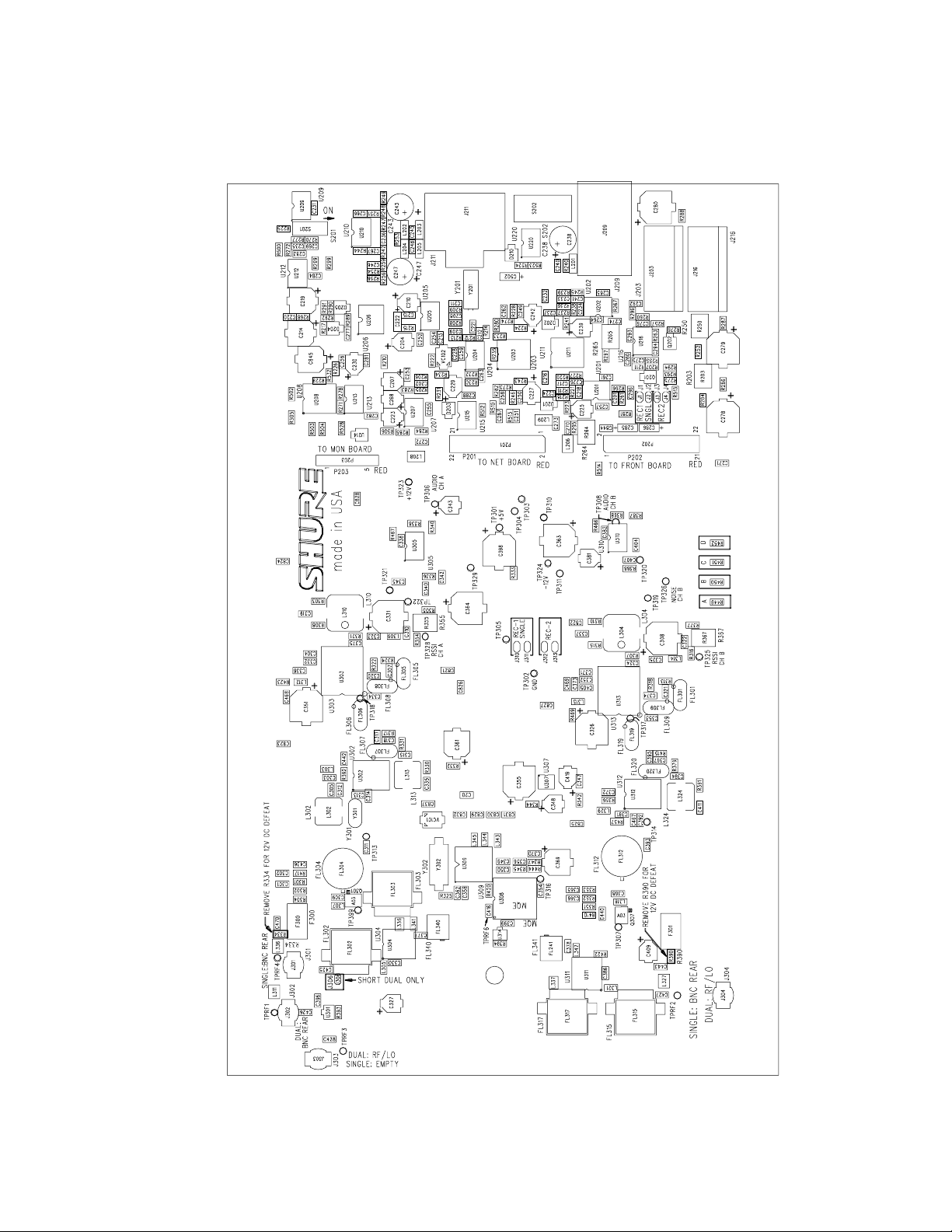
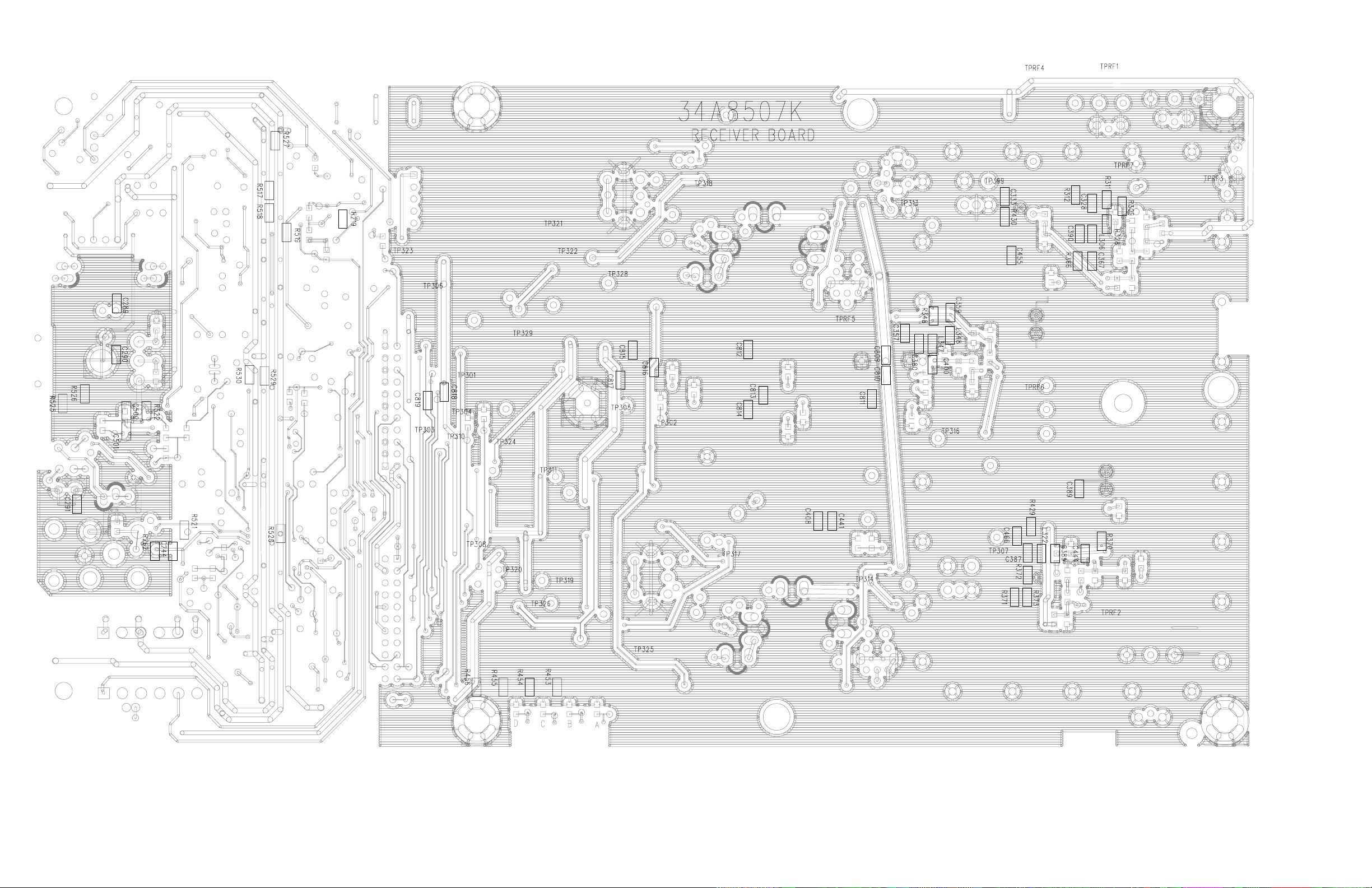
Shure U4 UHF Diversity Receiver
U4 Rf-Audio Printed Circuit Board Legend (Side 1)
25D1062 (TL) 45
Shure U4 Diversity UHF Receiver
U4 Rf-Audio Printed Circuit Board Legend (Side 2)
4625D1062 (TL)
 Loading...