

Page 1
I
222
HARTREY AVE., EVANSTON, IL.
222
HARTREY AVE., EVANSTON, IL.
MICROPHONES AND ELECTRONIC COMPONENTS
MICROPHONES AND ELECTRONIC COMPONENTS
AREA CODE
TWX:
3121866-2200
910-231-0048
60204
U.S.A.
60204
U.S.A.
*
CABLE: SHUREMICRO
TELEX:
72-4381
DATA
DATA
SHEET
MODEL THIOO
MODEL THIOO
PROFESSIONAL MOBILE,
PROFESSIONAL MOBILE,
TELEPHONE HANDSET
I
CONTROLLED MAGNETIC@
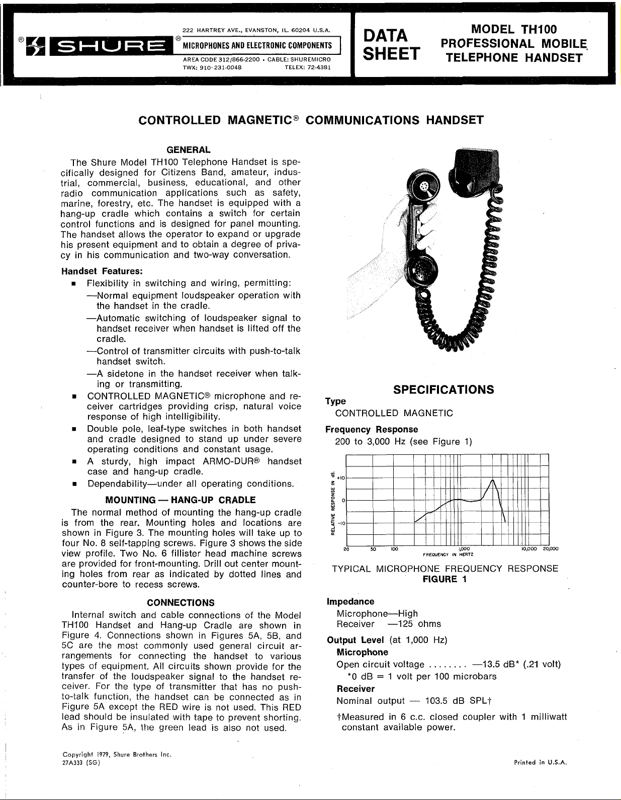
GENERAL
The Shure Model TH100 Telephone Handset is spe-
cifically designed for Citizens Band, amateur, industrial, commercial, business, educational, and other
radio communication applications such as safety,
marine, forestry, etc. The handset is equipped with a
hang-up cradle which contains a switch for certain
control functions and is designed for panel mounting.
The handset allows the operator to expand or upgrade
his present equipment and to obtain a degree of privacy in his communication and two-way conversation.
Handset Features:
Flexibility in switching and wiring, permitting:
-Normal equipment loudspeaker operation with
the handset in the cradle.
-Automatic switching of loudspeaker signal to
handset receiver when handset is lifted off the
cradle.
-Control of transmitter circuits with push-to-talk
handset switch.
-A sidetone in the handset receiver when talk-
ing or transmitting.
CONTROLLED MAGNETIC@ microphone and receiver cartridges providing crisp, natural voice
response of high intelligibility.
Double pole, leaf-type switches in both handset
to
and cradle designed
operating conditions and constant usage.
A sturdy, high impact ARMO-DUR@ handset
case and hang-up cradle.
Dependability-under all operating conditions.
MOUNTING - HANG-UP CRADLE
The normal method of mounting the hang-up cradle
is from the rear. Mounting holes and locations are
3.
shown in Figure
No. 8 self-tapping screws. Figure 3 shows the side
four
view profile. Two No.
The mounting holes will take up to
6
are provided for front-mounting. Drill out center mounting holes from rear as indicated by dotted lines and
counter-bore to recess screws.
CONNECTIONS
Internal switch and cable connections
THIOO Handset and Hang-up Cradle are shown in
4.
Figure
5C
Connections shown in Figures
are the most commonly used general circuit ar-
rangements for connecting the handset to various
types of equipment.
All
transfer of the loudspeaker signal to the handset re-
ceiver. For the type of transmitter that has no push-
to-talk function, the handset can be connected as in
Figure 5A except the RED wire is not used. This RED
lead should be insulated with tape to prevent shorting.
As
in Figure
5A,
the green lead is also not used.
stand up under severe
fillister head machine screws
of
the Model
5A,
58,
and
circuits shown provide for the
COMMUNICATIONS HANDSET
SPEC
Type
CONTROLLED MAGNETIC
Frequency Response
200
to
3,000
Hz (see Figure
m
-
+I0
z
-
w
z
go
W
w
!j
-10
J
W
(L
20
M
100
TYPICAL MICROPHONE FREQUENCY RESPONSE
Impedance
Microphone-High
Receiver -125 ohms
Output Level
Microphone
Open circuit voltage
*O
Receiver
Nominal output
tMeasured in
constant available power.
dB
(at
=
1
FREWENCY
FIGURE
1,000
volt per
-
6
C.C.
I
FI
CAT1
0
NS
1)
1.000
IN
HERTZ
1
Hz)
. .
. . .
100
103.5
-13.5
. . .
microbars
dB SPLI-
closed coupler with 1 milliwatt
dB*
10.000
(.21
20,000
volt)
I
Copyright
27A333
(SG)
1979,
Shure Brothers
Inc.
Printed
in
U.S.A.
Page 2
Switch
Handset - Press-to-talk bar-type switch to operate
transmitter circuit and external control circuit.
Cradle
speaker output to handset receiver and operate control circuit.
Cable
1.2m
jacketed coil cord on handset
1.2m
jacketed cable on hang-up cradle
Case
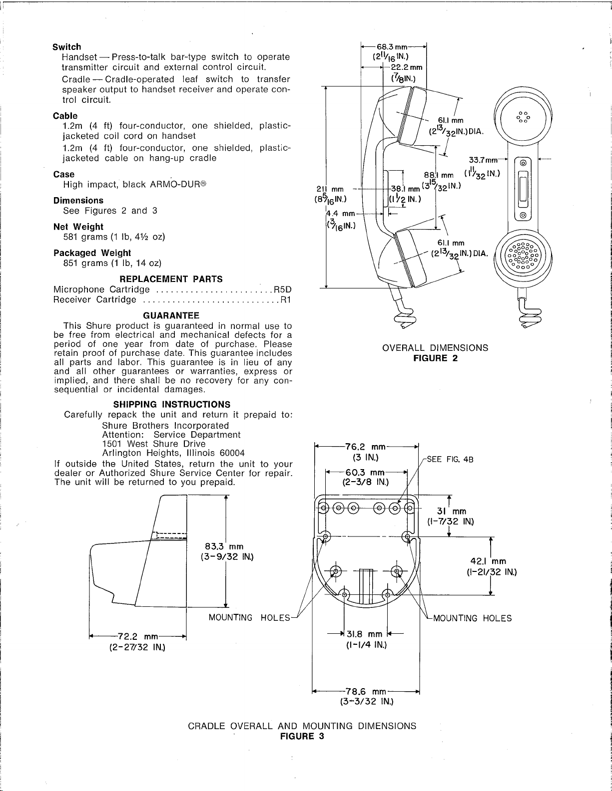
Dimensions
Net Weight
Packaged Weight
Microphone Cartridge
Receiver Cartridge
be free from electrical and mechanical defects for a
period of one year from date of purchase. Please
retain proof of purchase date. This guarantee includes
all parts and labor. This guarantee is in lieu of any
and all other guarantees or warranties, express or
implied, and there shall be no recovery for any consequential or incidental damages.
If outside the United States, return the unit to your
dealer or Authorized Shure Service Center for repair.
The unit will be returned to you prepaid.
-
Cradle-operated leaf switch to transfer
(4
ft) four-conductor, one shielded, plastic-
(4
ft) four-conductor, one shielded, plastic-
High impact, black ARMO-DUR@
See Figures 2 and
grams
581
851
This Shure product is guaranteed in normal use to
Carefully repack the unit and return it prepaid to:
(1
grams (1 Ib,
REPLACEMENT PARTS
SHIPPING INSTRUCTIONS
Shure Brothers Incorporated
Attention: Service Department
1501 West Shure Drive
Arlington Heights, Illinois
3
Ib,
4%
oz)
14
oz)
........................
............................
GUARANTEE
60004
R5D
R1
76.2
(3
IN.)
60.3
OVERALL DIMENSIONS
FIGURE
mm
mm
SEE
2
FIG.
48
b72.2
mm4
(2-27/32
IN.)
b-+*
A,,,
-78.6
CRADLE OVERALL AND MOUNTING DIMENSIONS
FIGURE
3
mm
(l-l/4
IN.)
mm---m
(3-3/32
IN.)
(I-7/32
U-MOUNTING
IN.)
HOLES
!
Page 3

RECEIVER
TRANSMITTER
BLUE
SWITCH BUTTON
MOVEMENT
GREEN
7
r,
(3
w
I
--___
I,
1;
-
-
[CONNECTION MADE
THRU BRACKET
I
m
GREEN
7,
WHITE
;.I
SHIELD
RED
BLACK
SWITCH
MOVEMENT
TELEPHONE
HANDSET
I
I
I
I
INTERNAL CONNECTIONS
C.B. EQUIPMENT
G ROU N DED RE LAY CI RCU IT
FIGURE
CONNECT THE SHIELD OF THE CABLE FROM THE HANG-UP CRADLE
I.
TO THE GROUND CONNECTION ON THE TRANSMITTER MICROPHONE
SOCKET.
2.
CONNECT THE WHITE WIRE TO THE MICROPHONE (HOT) SIGNAL
INPUT ON THE MICROPHONE SOCKET.
CONNECT THE RED WIRE TO THE RELAY CONNECTION ON THE
3.
TRANSMITTER MICROPHONE SOCKET.
4.
DISCONNECT THE GROUND RETURN WIRE OF THE SPEAKER, AN0
CONNECT THE WIRE FROM THE SPEAKER TO THE BLACK WIRE FROM
THE HANG-UP CRADLE CABLE.
THE GREEN WIRE
5.
IS
NOT USED.
5A
FIGURE
HANG-UP
4
I.
AT THE REAR
GREEN LEADS FROM UNDER THE SCREW HOLDING THE METAL
BRACKET. RETIGHTEN THIS SCREW SECURELY. RELOCATE THE
GREEN LEADS ON BOSS INDICATED
N0.5 SELF-TAPPING SCREW PROVIDED. THIS REMVES
GREEN
CONNECT THE SHIELD OF THE CABLE FROM THE HANG-UP CRADLE
2.
TO THE GROUND CONNECTION ON THE TRANSMITTER MICROPHONE
SOCKET.
CONNECT THE WHITE WIRE TO THE MICROPHONE (HOT) SIGNAL
3.
INPUT ON THE MICROPHONE SOCKET.
CONNECT THE RED WIRE TO THE RELAY CONNECTION ON THE
4.
TRANSMITTER MICROPHONE SOCKET.
5.
DISCONNECT THE GROUND RETURN WIRE OF THE SPEAKER, AND
CONNECT THE WIRE FROM THE SPEAKER TO THE BLACK WIRE FROM
THE HANG-UP CRADLE CABLE.
6.
CONNECT THE GREEN WIRE FROM THE HANG-UP CRADLE TO THE
OTHER RELAY CONNECTION ON THE TRANSMITTER MICROPHONE
SOCKET.
GREEN-NO
RED
WHITE
SHIELD
BLACK
OF
LEADS
FROM
CONNECTION
h
___
\I
MICROPHONE
CRADLE
THE HANG-UP CRADLE ASSEMBLY, REM3VE THE
IN
THE
GROUND
I
,$\.
I = I
;
=
1-1
,-,
i,i
SOCPET
FIGURE 2 USING THE
CONNECTION.
~~~$!$~~~~
GROUND
MICROPHONE
RETURN
IIPGROUND
INPUT
I
~
~.
THE
-
ADDED
WIRE
C.B.
EQUIPMENT
UNGROUNDED RELAY CIRCUIT
FIGURE
5B
DIRECT SWITCHING CIRCUIT
FIGURE
I.
CONNECT THE SHIELD
TO THE GROUND CONNECTION ON THE TRANSMITTER MICROPHONE
I
I
SOCKET.
CONNECT THE WHITE WIRE TO THE MICROPHONE (HOT) SIGNAL
2.
INPUT ON THE MICROPHONE SOCKET.
CONNECT THE RED
3.
THE TRANSMITTER
CONNECT THE BLACK WIRE TO THE SPEAKER GROUND RETURN.
4.
THE GREEN WIRE
5.
OF
THE CABLE FROM THE HANG-UP CRADLE
WIRE TO THE TRANSMI
MICROPHONE SOCKET.
IS
NOT USED.
5C
GROUND RETURN ON
TTER
Page 4

 Loading...