

Page 1
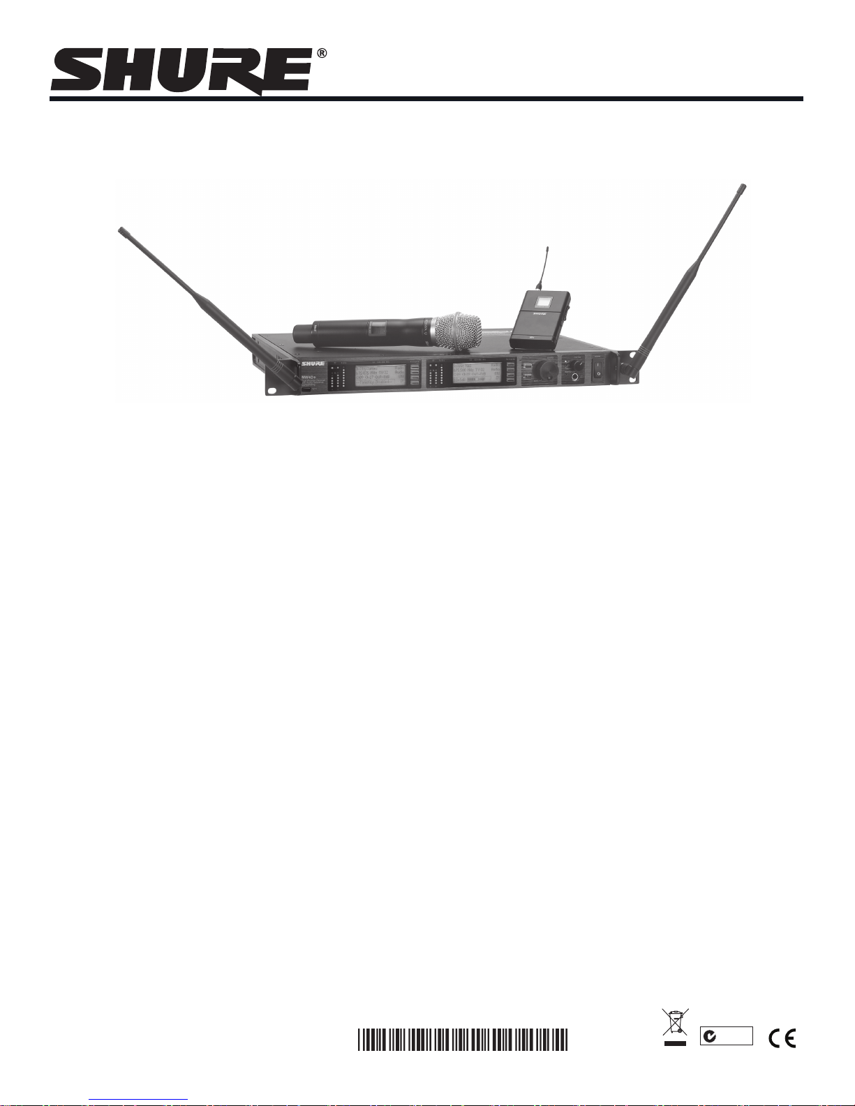
Model UHF-R®MW Wireless User Guide
Model UHF-R®MW Wireless User Guide ........................................................................................5
モデル UHF-R
모델 UHF-R
®
MW ワイヤレス 取扱説明書 ............................................................................................................. 21
®
MW Wireless 사용자 안내서 ...................................................................................41
©2013 Shure Incorporated
27A20022 (Rev. 3)
Printed in U.S.A.
N108
Page 2

Page 3
English
중요 안전 지침
1. 이 지침을 정독해 주십시오.
2. 이 지침을 잘 보관해 주십시오.
3. 모든 경고에 유의하십시오.
4. 모든 지침을 준수하십시오.
5. 이 기기를 물 가까이에 두고 사용하지 마십시오.
6. 마른 수건으로만 닦으십시오.
7. 통풍구를 막지 마십시오. 적합한 환기를 위해 충분히 거리를 두고 제조업체의 안내
서에 따라 설치하십시오.
8. 개방된 화염, 난방기, 방열 조절기, 스토브, 기타 열을 발산하는 기기 (앰프포함) 등
의 열원 근처에 설치하지 마십시오. 제품 위에 개방된 화염원을 올려 놓지 마십시오.
9. 안전을 위해 유극 또는 접지 타입의 플러그를 반드시 사용하십시오. 유극 유형의 플
러그는 넓은 핀과 좁은 핀, 두 개의 핀으로 구성되어 있습니다. 접지형 플러그에는
두 개의 핀과 하나의 접지 단자가 있습니다. 넓은 핀이나 접지 단자는 사용자의 안전
을 위한 것입니다. 제공된 플러그가 콘센트에 맞지 않으면 전기 기사에게 문의하여
콘센트를 교체하십시오.
10. 전원 코드는 밟히지 않도록 주의하고 특히 전원 플러그 사이, 접속 소켓 및 기기에서
나오는 부분에 전원 코드가 끼이지 않도록 보호하십시오.
11. 제조업체가 지정한 부속품/액세서리만 사용하십시오.
12. 제조업체에서 지정하거나 기기와 함께 판매되는 카트, 스탠드, 받침대, 브
라켓 또는 테이블에서만 사용하십시오. 카트를 사용하는 경우, 이동 시 카
트와 기기가 넘어져 부상을 입지 않도록 주의하십시오.
13. 낙뢰시 또는 장기간 사용하지 않을 때는 기기의 전원을 빼놓으십시오.
14. 모든 서비스는 자격을 갖춘 서비스 전문가에게 의뢰하십시오. 전원 코드나 플러그
가 손상된 경우, 기기 안으로 액체가 들어가거나 물건을 떨어뜨린 경우, 기기가 비나
물에 젖은 경우, 기기가 정상적으로 작동하지 않는 경우 또는 기기를 떨어뜨린 경우
와 같이 기기가 손상되었을 때는 서비스를 받아야 합니다.
15. 기기에 물을 떨어뜨리거나 뿌리지 마십시오. 화병과 같이 물이 담긴 물체를 기기 위
에 올려놓지 마십시오.
16. MAINS 플러그나 기기용 커플러는 작동가능한 상태로 남아 있어야 합니다.
17. 기기의 공기매개 잡음은 70dB을 초과하지 않아야 합니다.
18. CLASS I 구조의 기기는 MAINS 소켓 콘센트에 보호 접지 연결 방식으로 연결되어
야 합니다.
19. 화재나 감전 위험을 줄이려면 이 기기를 빗물 또는 습기에 노출시키지 마십시오.
20. 이 제품을 고치려고 시도하지 마십시오. 그렇게 하면 사람이 다치거나 제품이 고장
을 일으킬 수 있습니다.
21. 이 제품은 명시된 작동 온도 범위내에서 사용하십시오.
이 기호는 기기에 전기 쇼크 위험을 유발하는 위험한 전압이
흐른다는 것을 의미합니다.
이 기호는 이 기기와 함께 제공된 문서에 중요한 작동 및 유지
보수 지침의 내용이 들어 있다는 것을 의미합니다.
IMPORTANT SAFETY INSTRUCTIONS
1. READ these instructions.
2. KEEP these instructions.
3. HEED all warnings.
4. FOLLOW all instructions.
5. DO NOT use this apparatus near water.
6. CLEAN ONLY with dry cloth.
7. DO NOT block any ventilation openings. Allow sufficient distances for adequate ventilation and install in accordance with the manufacturer’s instructions.
8. DO NOT install near any heat sources such as open flames, radiators, heat registers,
stoves, or other apparatus (including amplifiers) that produce heat. Do not place any open
flame sources on the product.
9. DO NOT defeat the safety purpose of the polarized or groundingtype plug. A polarized
plug has two blades with one wider than the other. A grounding type plug has two blades
and a third grounding prong. The wider blade or the third prong are provided for your
safety. If the provided plug does not fit into your outlet, consult an electrician for replacement of the obsolete outlet.
10. PROTECT the power cord from being walked on or pinched, particularly at plugs, convenience receptacles, and the point where they exit from the apparatus.
11. ONLY USE attachments/accessories specified by the manufacturer.
12. USE only with a cart, stand, tripod, bracket, or table specified by the manufacturer, or sold with the apparatus. When a cart is used, use caution when
moving the cart/apparatus combination to avoid injury from tip-over.
13. UNPLUG this apparatus during lightning storms or when unused for long
periods of time.
14. REFER all servicing to qualified service personnel. Servicing is required when the apparatus has been damaged in any way, such as power supply cord or plug is damaged,
liquid has been spilled or objects have fallen into the apparatus, the apparatus has been
exposed to rain or moisture, does not operate normally, or has been dropped.
15. DO NOT expose the apparatus to dripping and splashing. DO NOT put objects filled with
liquids, such as vases, on the apparatus.
16. The MAINS plug or an appliance coupler shall remain readily operable.
17. The airborne noise of the Apparatus does not exceed 70dB (A).
18. Apparatus with CLASS I construction shall be connected to a MAINS socket outlet with a
protective earthing connection.
19. To reduce the risk of fire or electric shock, do not expose this apparatus to rain or
moisture.
20. Do not attempt to modify this product. Doing so could result in personal injury and/or
product failure.
21. Operate this product within its specified operating temperature range.
This symbol indicates that dangerous voltage constituting a risk of
electric shock is present within this unit.
This symbol indicates that there are important operating and maintenance instructions in the literature accompanying this unit.
WARNING: This product contains a chemical known to the State of California to cause cancer and birth
defects or other reproductive harm.
3
Page 4

Shure UHF-R® MW Wireless
4
Page 5

English
Contents
Important Safety Instructions ............................................................................................................................................................... 3
Feature Overview ................................................................................................................................................................................ 6
System Components ........................................................................................................................................................................... 7
Receiver Controls and Connectors ...................................................................................................................................................... 8
Receiver LCD Interface ...................................................................................................................................................................... 9
Receiver Parameters ........................................................................................................................................................................... 9
Connecting Multiple Receivers to the RF Distribution Ports ............................................................................................................... 10
Automatic Frequency Selection ......................................................................................................................................................... 11
Networking Receivers ........................................................................................................................................................................ 12
Handheld and Bodypack Transmitter Controls and Connectors ....................................................................................................... 13
Transmitter LCD Interface ................................................................................................................................................................. 13
Transmitter Batteries ......................................................................................................................................................................... 13
Transmitter Parameters ..................................................................................................................................................................... 14
Setting Transmitter Gain .................................................................................................................................................................... 14
RF Safety Mode ................................................................................................................................................................................. 14
Automatic Transmitter Sync .............................................................................................................................................................. 15
Troubleshooting ................................................................................................................................................................................. 16
Specifications .................................................................................................................................................................................... 17
Replacement Parts and Accessories ................................................................................................................................................. 19
5
Page 6

Shure UHF-R® MW Wireless
Feature Overview
The UHF-R
rugged and reliable. It is easy to set up and operate with advanced features for professional installations requiring multiple wireless
microphone systems.
Frequency Band Selection
Shure offers wireless systems in a selection of bands that conform to the different government regulations of specific nations or
geographic regions. These regulations help limit radio frequency (RF) interference among different wireless devices and prevent
interference with local public communications channels, such as television and emergency broadcasts.
The system’s band and frequency range are identified on the face of the receiver and transmitter. For example, “X2 925–932 MHz.”
For information on bands available in your area, consult your local dealer or phone Shure. More information is also available at Shure’s
website (www.shure.com).
Groups and Channels
To transmit audio through a wireless system, the transmitter and receiver must be set to the same radio frequency, or channel. A
wide selection of channels allows more microphones to be used at the same time, since each microphone must operate on a different
channel. It also provides a greater choice of open channels—those that are free from interference from television broadcasts, electronic
devices, or other wireless systems.
A group is a selection of compatible channels. Wireless microphones work better together when set to channels in the same group.
Automatic Frequency Selection
The following features scan the RF environment to find the best group and channel settings for a particular installation.
• Group Scan—finds the group with the most open channels, then sets all networked receivers to channels in that group.
• Channel Scan—finds the first open channel in the currently selected group and sets the receiver to that channel.
Follow the steps on page 11 for instructions on using these features.
Automatic Transmitter Sync
This feature automatically transfers the group and channel settings from a receiver to a transmitter. You can also program other
transmitter settings on a receiver and transfer those settings too. See page 15.
Interface Lock
This feature locks the receiver and transmitters so that users cannot change settings. The transmitter power switch can also be
disabled so that the transmitter remains on if the power switch is accidentally toggled during a performance.
Audio Gain Structure
The following settings allow you to adjust audio gain throughout the system:
• Sensitivity (bodypack only). A 25 dB range of gain adjustment at the bodypack transmitter input.
• Transmitter Gain. A 30dB range of audio gain adjustment within the transmitter (affects audio level at the receiver, as
• Output Level. 32 dB of attenuation at the receiver output, plus a mute setting.
• Mic/Line switch. –30 dB pad for matching audio levels at the receiver XLR output.
Networking
Each receiver has an RJ-45 port on the back for connecting to other receivers over an Ethernet network. Networking receivers allows
you to automatically set channels for all the receivers with a single group scan command. You can also control and monitor all networked receivers through the Shure Wireless Workbench PC software.
RF Distribution Ports
Use the RF distribution ports to share the signal from a single pair of antennas with up to 10 single or dual receivers within the same
frequency band. The RF distribution ports eliminate the need for antenna splitters or distribution amplifiers. Active circuitry minimizes
insertion losses, preserving signal quality. Input filtering keeps the signal free from out-of-band interference. Distribution circuitry is
active only when additional receivers are connected to the RF distribution ports. When not used, the port circuitry is bypassed, allowing
the receiver to be used as a stand-alone component.
Shure Wireless Workbench Software
The Shure Wireless Workbench software on the supplied CD includes a variety of useful tools for installing and managing multiple
wireless systems. Simply install the software on your computer and connect it to a network of receivers to monitor and control receivers
and transmitters throughout the network. (See page 12 for more information on networking).
Instructions on using the Wireless Workbench software are available in the online help files after you install the software.
®
MW Wireless Microphone System uses the latest wireless technology, delivers outstanding audio clarity, and is
indicated by the Audio LEDS.)
6
Page 7
System Components
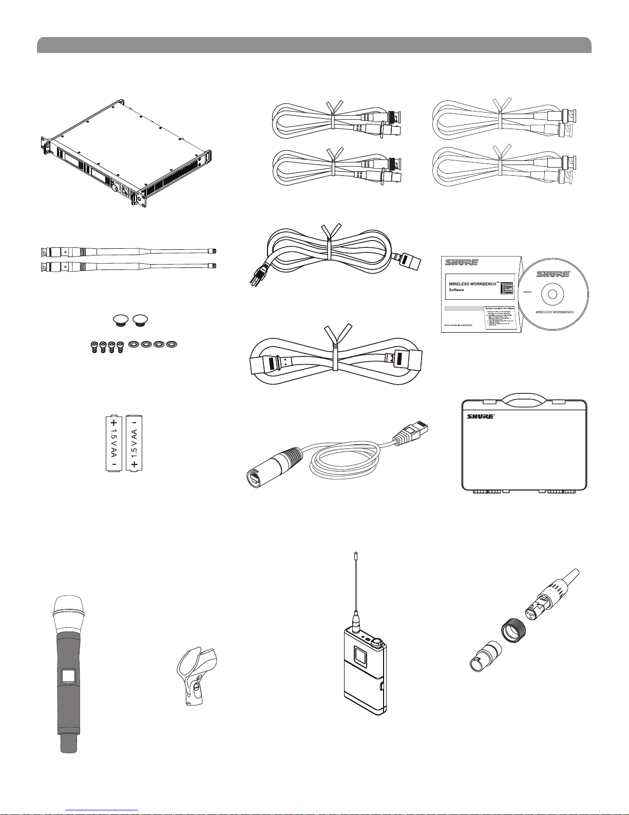
All systems include:
English
MW4D+ Receiver
Two 1/2 Wave Antennas
2 Antenna hole plugs
4 Rack Mount Screws with Washers
AA Batteries
Two Antenna Cables
IEC Power Cable
IEC Power Extension Cable
Ethernet Network Cable with “Ruggedized” plug
Two RF Distribution Cables
Shure’s Wireless Workbench Software
Transmitter Carrying Case
Handheld Systems Include:
Microphone Head (choice of SM58®, Beta 58A®, Beta
87A™, Beta 87C™ or KSM9/BK, KSM9/SL)
MW2 handheld transmitter
Microphone clip
Bodypack Systems Include:
Threaded TA4F Adapter
MW1
7
Page 8

Shure UHF-R® MW Wireless
Receiver Controls and Connectors
17
MW4D+
Wireless Receiver
with Audio Reference
Companding
sync
RF Audio
OL
A B
XX YYY-ZZZ MHz Navigate
2 4 5
RF Audio
OL
A B
XX YYY-ZZZ MHz Navigate
6
ENTER
EXIT
OFF
push
Monitor Clip
Monitor
7
8
Control
push
POWER
RF B out
antenna B in
12.7V out
150mA
9
10
11
balanced low Z
line
mic
12 13 14 15
18
receiver outputs
lift
GND
SYNC Infrared (IR) port. Transmits group, channel, and
other settings to a transmitter. See page 15.
Squelch LEDs.
• Blue (On) = Transmitter signal detected
• Off = no signal or signal squelched because of poor
reception or no tonekey
NOTE: The receiver will not output audio unless at least one
blue LED is illuminated.
RF LEDs. Indicate RF signal strength from the transmitter
at each antenna and diversity condition.
• Amber = normal
• Red = overload (greater than –25 dBm)
4 Audio LEDs. Indicate audio signal strength from
transmitter.
• Green = signal present
• Yellow = normal peak
• Red = overload
To correct this level, adjust the transmitter gain.
5 Indicates the name and range of receiver frequency
band.
LCD Interface. Provides a convenient way to program the
receiver from the front panel (see detail on next page).
7 Monitor. 1/4” output jack and volume knob for
headphones.
• Monitor Clip LED indicates headphone audio is clipping.
• Dual models: Push the knob to switch from receiver one
to receiver two.
200Ω
networking
balanced low Z
network
activity
line
ethernet
mic
RJ-45
16
receiver outputs
200Ω
lift
GND
antenna A in
12.7V out
150mA
11
RF A out
18
Power switch. Powers the unit on and off.
AC mains power input, IEC connector. 100–240 Vac.
AC mains power passthrough (unswitched). Use
IEC extension cables to connect up to five UR4D+
receivers to a single AC power source.
Diversity antenna inputs A and B.
Note: Antenna inputs are DC biased. Use only antenna
combiners and accessories listed in page 19. Some types of
antenna splitters or other products may short the DC power
and damage the receiver.
Mic/Line switch. Changes output level 30 dB (XLR
output only).
Electrically balanced XLR output jack
Lift/GND switch. Lifts ground from Pin 1 of the XLR
connector (default = GND).
Impedance balanced 1/4” output jack (200Ω)
RJ-45 jack for Ethernet network interface. Accepts both
regular and “ruggedized” RJ-45 plugs.
Temperature-activated fan ensures top performance in
high temperature environments. Clean fan screen as
needed to remove dust.
The RF distribution ports pass the RF signal from one
receiver to the next, allowing a maximum of 10 receivers
to share a single pair of antennas.
8
Page 9
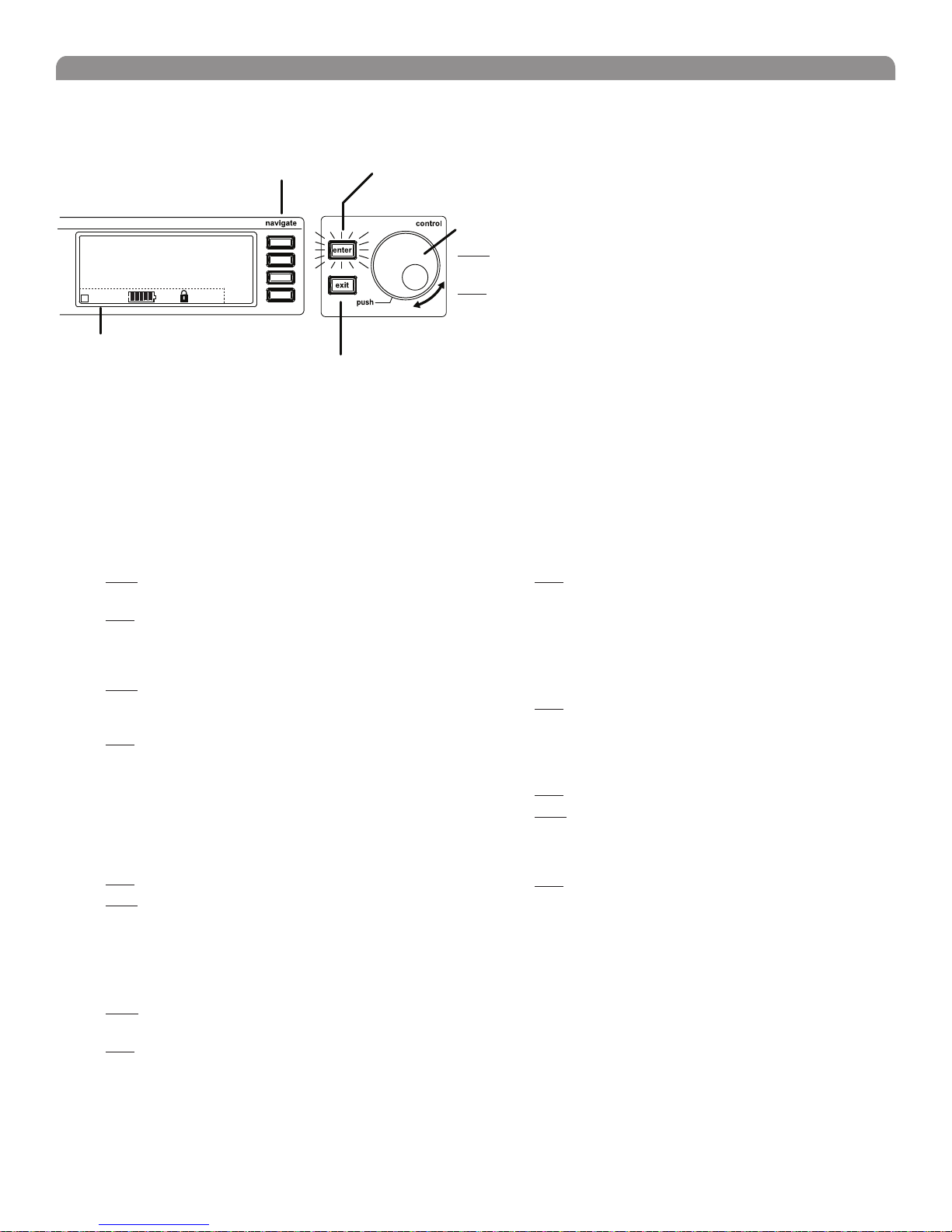
Receiver LCD Interface
Menu Access
Press the Navigate key next to the menu
item you want to select.
English
Accept Changes
After changing a parameter, the ENTER button flashes.
Press it to save the value.
SHURE
524-025 MHz TV: 32
G: 3 Ch: 1 Out: -0dB
+12 dB
+
Hi
F, P, FP
Radio
Audio
Util
Sync
Cursor Control
Push the Control wheel to move
the cursor to the next item.
Turn the Control wheel to change
a parameter value.
Transmitter Status Display
Everything under the dotted line reflects
the settings for the transmitter, if present.
(main title screen only).
Exit/Cancel
Press the Exit button to cancel changes
and return to the previous menu.
Receiver Parameters
Use the following instructions to set parameters through the LCD interface.
NOTE: After adjusting a parameter, you must press the flashing ENTER button to accept the change.
Group and Channel
Menu: Radio
• Push the Control wheel to move the cursor to the
Group (G) or Channel (Ch) parameter.
• Turn the Control wheel to change the parameter.
Frequency
Menu: Radio
• Push the Control wheel to move the cursor to the
integer value (524.025 MHz) or fractional value
(524.025).
• Turn the Control wheel to change the value.
Automatic Transmitter Sync
Menu: Sync
• See page 15.
Receiver Name
Menu: Util
• Turn the Control wheel to change the letter.
• Push the Control wheel to move to the next letter.
Output Level
Menu: Audio
This setting adjusts the signal level at the XLR and 1/4” audio
output jacks.
• Turn the Control wheel to change the relative level in
dB. (0 dB to –32 dB).
• Turn the wheel all the way down to mute the outputs.
Squelch
Menu: Radio > Squelch
Receiver Lock
When locked, the receiver settings cannot be changed from the
front panel. However, you can still navigate the LCD menu to view
the settings (and turn the lock off).
Menu: Util > Lock
LCD View
Menu: Util > Title
LCD Contrast
Menu: Util > Contrast
Tonekey
Menu: Radio > Squelch > Tonekey
Tonekey squelch mutes the outputs unless the receiver detects a
transmitter. Tonekey should be left on (On) except for certain
troubleshooting operations.
• Turn the Control wheel to change the parameter
• Turn the Control wheel to toggle the lock on or off (ON
or OFF).
• Turn the Control wheel to mark an item for display.
• Push the Control wheel to move to the next item.
• Turn the Control wheel to increase or decrease contrast.
9
Page 10
Shure UHF-R® MW Wireless
Network Parameters
NOTE:
• The receiver reboots after you press ENTER to accept
network parameter changes
• In dual models (MW4D+), these settings affect both
receivers (the dual receiver is treated as a single network
device).
Set the Receiver Network Mode
Menu: Util > Network
1. Push the Control wheel to move the cursor to the
Mode parameter.
2. Turn the Control wheel to set the receiver to one of the
following values:
• DHCP: use this setting when connecting the receiver to a
DHCP server.
• Manual: allows you to set the receiver to a specific IP
address or subnet.
IP Address and Subnet
Menu: Util > Network
NOTE: To change these settings, the network mode
must be set to Manual.
1. Push the Control wheel to move the cursor to any of
the following parameters:
• IP (IP address)
• Sub (Subnet mask)
2. Turn the Control wheel to change the value.
Device ID
Assists in identifying receivers through the Wireless Workbench
Software (has no effect on network identification).
Menu: Util > Network
1. Push the Control wheel to move the cursor to the
DevID parameter.
2. Turn the Control wheel to set the receiver to change
the value.
Custom Groups
This feature allows you to create your own groups of frequencies.
Creating new groups...
Menu: Radio > Custom
1. Turn the Control wheel to select a custom group
number (U1, U2, U3, etc.)
2. Push the Control wheel to move to the Channel
parameter and turn it to select a channel (01, 02,
03, etc.)
3. Push the Control wheel to move to the Freq
parameter and select a frequency for that channel.
4. Push the NEXT menu key to select a frequency for the
next channel in that group.
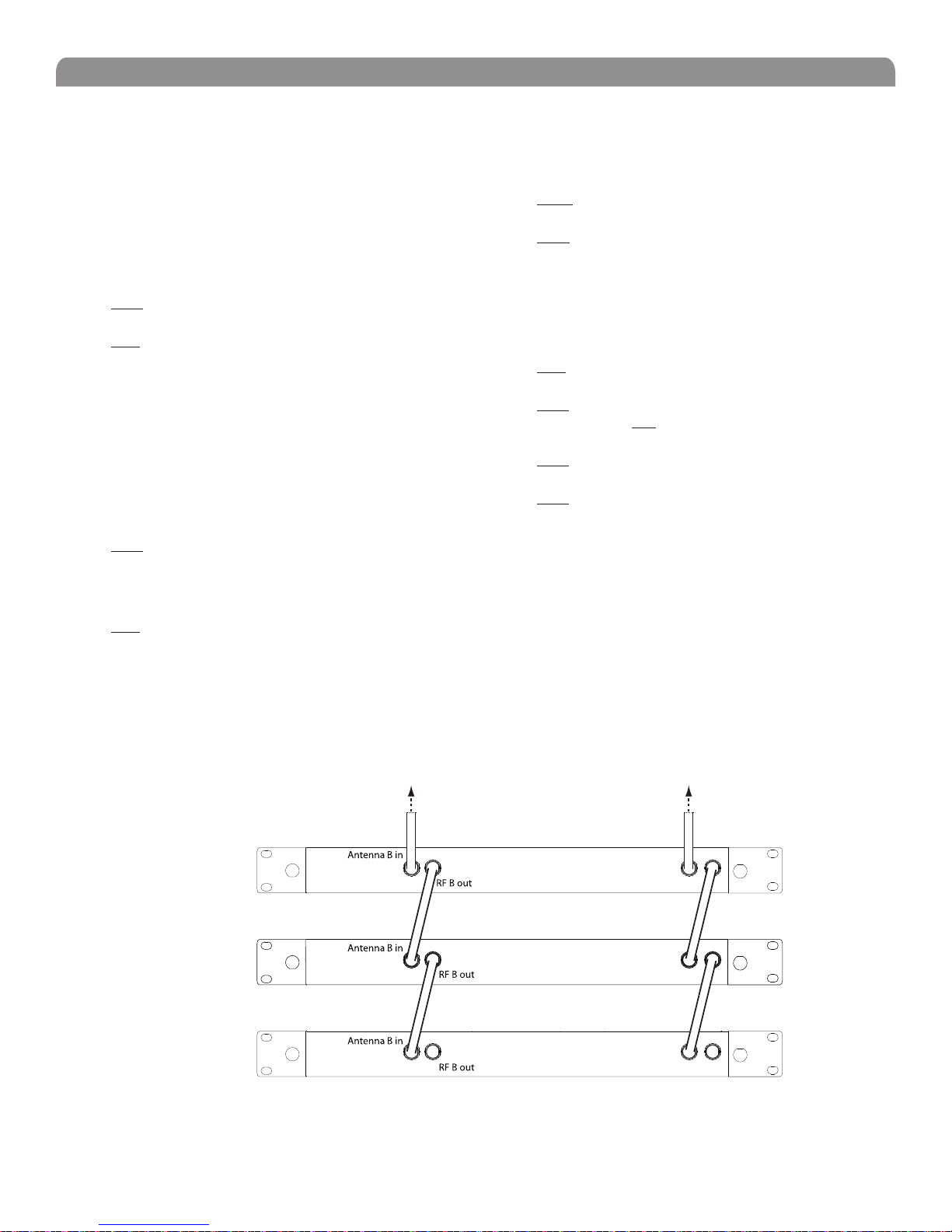
Connecting Multiple Receivers to the RF Distribution Ports
The RF distribution ports pass the RF signal from one receiver to the next, allowing a maximum of 10 receivers to share a single pair of
antennas. Use the supplied RF distribution cables to connect the ports of each receiver as shown.
NOTE: All receivers must be operating in the same frequency band.
To Antenna ATo Antenna B
Antenna A in
First Receiver
Antenna A in
Additional Receivers
Antenna A in
Last Receiver
RF A out
RF A out
RF A out
10
Page 11

English
Automatic Frequency Selection
Follow these steps to use the channel scan and group scan features.
Before you begin...
• Install the receivers in the location where they will be used and power them on.
• Mute all inputs on mixing devices connected to receivers.
• Turn off all bodypack or handheld transmitters for the systems you are setting up.
• Turn on potential sources of interference such as other wireless systems or devices, computers, CD players, effects
processors, and digital rack equipment so they are operating as they would be during the presentation or performance.
Single Receiver
1. Select Radio > Scan > Chan Scan using the Navigate keys on the receiver LCD interface.
2. Turn the Control wheel to select a group.
3. Press Chan Scan. The display indicates that the receiver is searching. Once it has finished, it displays the selected channel.
4. Press the flashing ENTER button to accept the suggested channel.
5. Sync the transmitter (see page 15).
Networked or Dual Receivers
With networked or dual receivers, you can take advantage of the group scan feature to set group and channel settings for all the
receivers at the same time. (See page 11 for instructions on networking.)
Perform a group scan from any receiver...
1. Select Radio > Scan> Group Scan using the Navigate keys on the receiver LCD interface. The display indicates that
the receiver is searching (Scan In Progress). Once it has finished, it displays the group with the most open channels.
2. If you wish, turn the Control wheel to change groups. The number of open channels for each group is displayed.
3. Press the flashing ENTER button to set all receivers to open channels in that group.
NOTE: The group scan feature only works for receivers in the same frequency band.
Multiple Receivers—Not Networked
If your receivers are not networked (or in different bands), the group scan cannot automatically set their group and channel settings.
However, you can still take advantage of the group scan feature to find the group with the most open channels and the channel scan
feature to find open channels in that group.
Find the group with the most open channels...
Perform a group scan using the steps for a networked receiver (above). However, make a note of the selected group before pressing
the flashing ENTER button to accept it.
Set the receivers to open channels in that group...
Perform a channel scan on the remaining receivers using the steps for a single receiver (above). Make sure to select the same group
for each receiver before performing the channel scan.
IMPORTANT: After setting the channel for the first receiver, immediately sync the transmitter for that receiver and leave it on so that the
next receiver detects that channel during its channel scan. Otherwise, all the receivers will be set to the same open channel.
11
Page 12
Shure UHF-R® MW Wireless
Networking Receivers
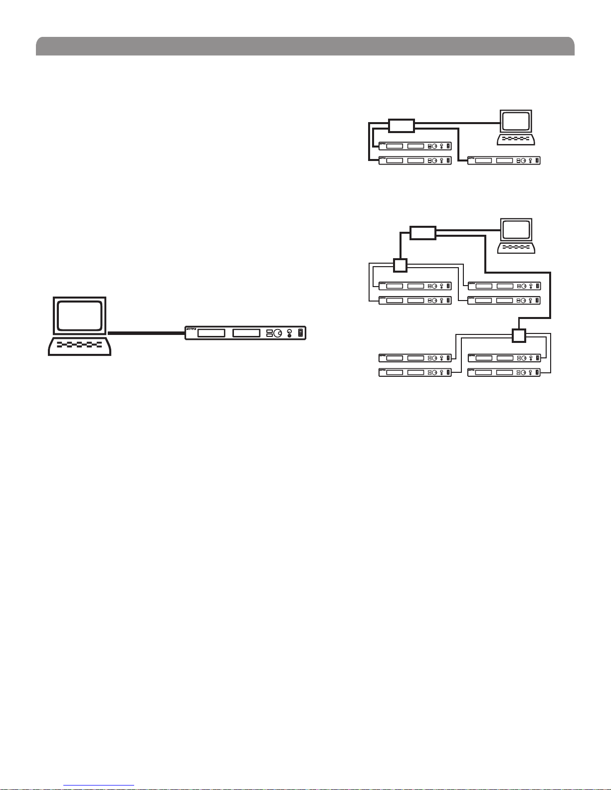
Basic Network
Connect receivers to an Ethernet router with DHCP service. Use Ethernet
switches to extend the network for larger installations.
Use the receiver’s default network setting
(Util > Network > Mode = DHCP).
Accessing the Network with a Computer
If you want to use the Wireless Workbench software, connect your computer to
the network and install the software from the CD that came with the receiver.
Make sure your computer is configured for DHCP (from Control Panel, click
Network Connections. Double-click on Local Area Connection. Select
Internet Protocol (TCP/IP) and click Properties. Select Obtain IP address
automatically and Obtain DNS server address automatically and click OK).
NOTE: Some security software or firewall settings on your computer can
prevent you from connecting to the receivers. If using firewall software, allow
connections on port 2201.
Router with DHCP
Router with DHCP
Switch
Computer
(optional)
Computer
(optional)
Ethernet
Switch
Static IP Addressing
The receiver also supports static IP addressing. Assign your own IP addresses ( Util > Network > Mode = Manual). See
“Network Parameters” on page 10.
NOTE: Dual receivers use a single IP address, which may be set through either LCD interface.
12
Page 13
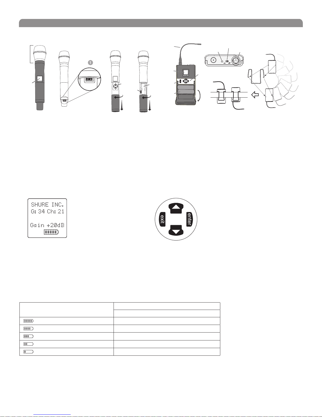
Handheld and Bodypack Transmitter Controls and Connectors
English
Interchangeable microphone head (BETA 87A pictured).
LCD Panel.
Power Switch.
Control buttons for LCD interface.
Infrared (IR) port. See page 14.
Transmitter LCD Interface
Battery compartment.
Flexible Antenna.
Power LED.
4-Pin Microphone Input Jack.
Reversible Belt Clip.
Up Arrow Key. Scroll up
or increase a value.
524.025MHz
Main Menu
exit Key. Move to the left, or
exit without saving changes.
Down Arrow Key. Scroll
down or decrease a value.
enter Key. Press to select parameters
and accept the selected value.
Transmitter Batteries
Transmitters operate on standard AA batteries. Turn off the transmitter before changing the batteries.
The battery fuel gauge displayed on the transmitter LCD gives an indication of remaining battery life, as shown below.
Transmitter Display Approximate Hours Remaining (alkaline batteries)
MW1, MW2
7.5 to 9.5
5.75 to 7.5
4 to 5.75
2 to 4
15 minutes to 2 hours
13
Page 14
Shure UHF-R® MW Wireless
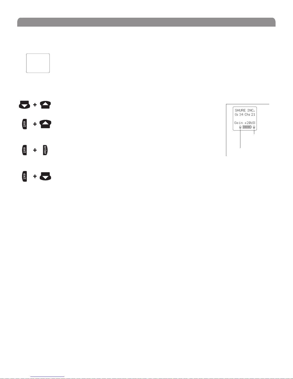
Transmitter Parameters
Press ENTER from the main menu to access the following parameters:
Group (G) and Channel (Ch). Must match the receiver’s settings.
G:34 Ch:21
524.025MHZ
Gain +20dB
SHURE INC.
Use the following key combinations to access additional features and parameters:
hold tap
hold tap
hold tap
Frequency (MHz). Manual frequency selection in 0.025 MHz increments.
Gain (Gain). Adjusts audio level from –10 dB to +20 dB
Sensitivity (Sens) (bodypack only).
Sets audio input to +15 dB, 0 dB, or –10 dB recommended for guitars.
Name Display. 12-digit ASCII.
LCD Panel
Changes LCD Panel
Frequency Lock
Toggles setting. When enabled, frequency cannot be changed, and a transmitter
sync will not overwrite the frequency setting.
Power Lock
Toggles power lock. When locked, power switch does not turn off transmitter.
Lock Indicators
524.025MHZ
Power Lock
Frequency Lock
hold tap
RF power level setting
Use the arrow keys to select normal 10 mW or low 2 mW power. Use the normal power setting to
conserve batteries or prevent RF overload at the receiver.
Setting Transmitter Gain
Adjust the transmitter gain and input sensitivity so that the Audio LEDs on the receiver peak within the yellow range during use. On
the bodypack transmitter, you can change the sensitivity setting to compensate for different audio levels when connecting different
intruments or microphones to the input.
To adjust gain, turn on the transmitter and press the enter button. Scroll down to the Gain parameter or the Sens parameter
(bodypack only) and press enter again. Use the arrow keys to adjust the setting and press enter to save it (Exit cancels without
saving).
RF Safety Mode
This special feature temporarily mutes RF broadcast. This allows you to change frequency settings on a transmitter without accidentally
“cutting in” on a channel being used by another transmitter.
1. Turn the transmitter off.
2. Hold down exit key while turning on the transmitter power (for handheld microphones, you need to pull the battery cover off the
handle). The LCD flashes while the unit is in RF safety mode.
3. Change group and channel settings as you normally would—the transmitter will not broadcast.
4. Power the transmitter off and on to exit RF safety mode.
14
Page 15
English
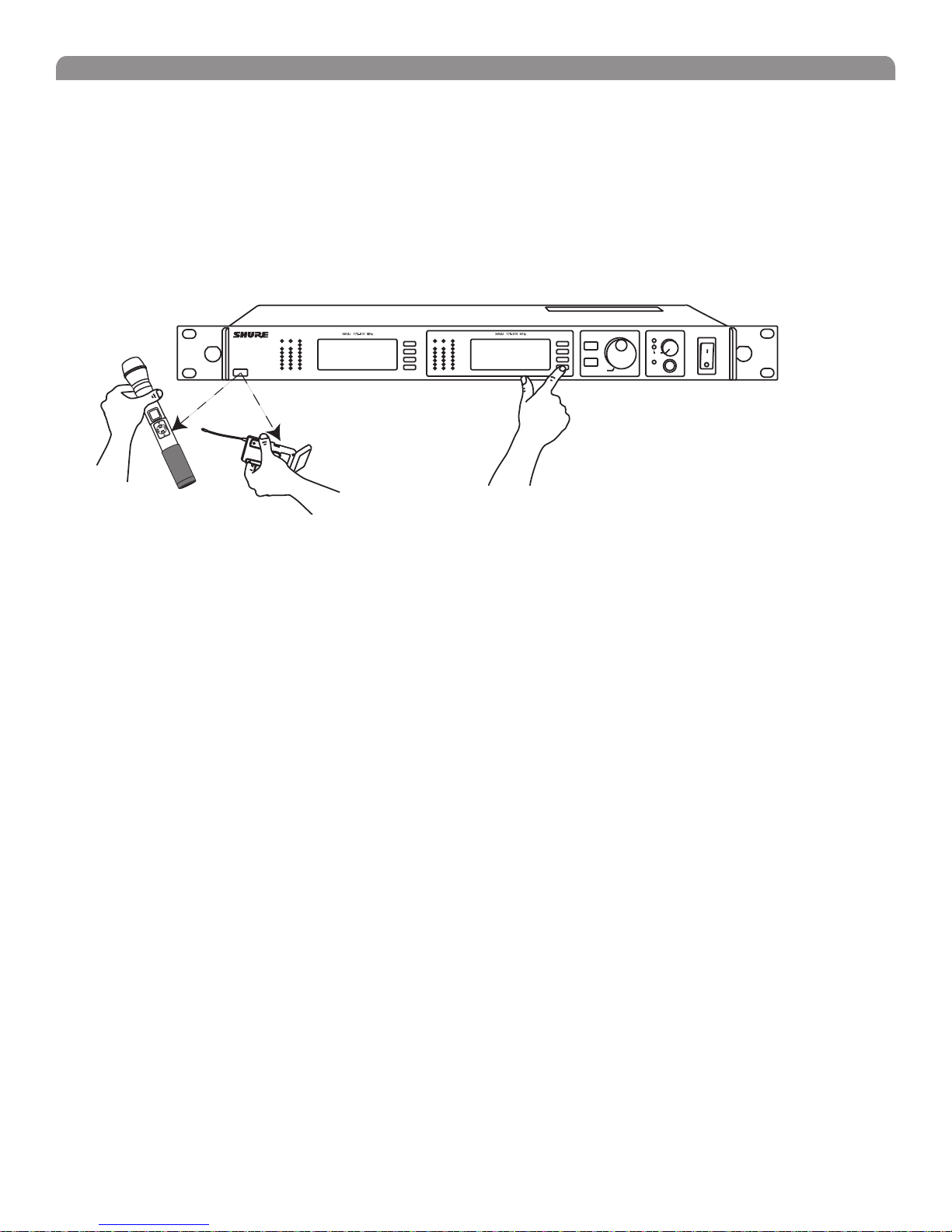
Automatic Transmitter Sync
This feature automatically updates a bodypack or handheld transmitter’s group and channel settings to match those of a selected
receiver.
To perform a transmitter sync...
1. Open the transmitter battery cover to display the infrared (IR) port.
2. With the IR port exposed to the receiver, select Sync > sync from the receiver LCD interface.
The display on the receiver indicates whether the sync was successful. If the sync fails, try again, making sure that the IR port on the
transmitter is exposed and directly faces the IR port on the receiver.
NOTE: Close the battery door before performing a sync on other transmitters.
®
MW4D+
Wireless Receiver
with Audio Reference
Companding
Audio NavigateRF
OL OL
sync
Audio NavigateRF
ENTER
EXIT
sync
Monitor
Control
Monitor Clip
Power
1
2
push
To transfer other transmitter settings...
Optionally, you can transfer other transmitter settings from a receiver when you perform a sync. Use the following steps:
1. Select Sync > Setup from the receiver LCD interface.
2. Turn the Control wheel to change parameter settings.
3. Push the Control wheel to move to the next parameter.
4. Push the flashing ENTER button to save the settings.
The transmitter settings you set on the receiver remain for future syncs.
NOTE: If you don’t want the sync to send a setting, set the parameter to No Change
Available Settings...
The following settings are available from the Sync > Setupmenu:
• Sensitivity (Sens) bodypack only
• Gain (Gain)
• RF Power (Pwr)
• Power and Frequency Lock (Lock), which has the following values:
Power lock only: (Pwr Only)
Frequency lock only: (Freq only)
Both: (Freq and Pwr)
Neither: (Unlocked)
• Custom Groups (CG):
On (ON): Send custom groups to transmitters during sync
Off (OFF): Do not send custom groups (reduces sync time)
15
Page 16

Shure UHF-R® MW Wireless
Troubleshooting
Issue See Solution...
No sound
Faint Sound or Distortion
Lack of range, unwanted noise bursts, or drop outs
Cannot turn transmitter off or change frequency settings, or can’t program receiver
Excessive hum or buzzing
Power, Cables, or RF
Gain
RF
Interface Locks
Ground lift
Power
Make sure that the transmitter and receiver are receiving sufficient
voltage. The receiver requires at least 90 Vac. Check the battery
indicator on the transmitter and replace battery if necessary.
Gain
Adjust the transmitter gain and sensitivity settings (see page 14) or
the receiver output level (page 9), or toggle the mic/line switch
on the back of the receiver.
Cables
Check that all cables and connectors are in working order.
Ground Lift
Lifting the ground on pin 1 of the XLR output on the receiver can
sometimes remove hum or buzz in the audio signal. Set the GND/
LIFT switch on the receiver to LIFT if you are using the XLR
connector.
Interface Locks
Both the transmitter and receiver can be locked to prevent accidental
changes. On transmitters, look for a lock symbol on the LCD and
use the key combinations illustrated on page 14 to turn it off.
To turn off the receiver interface lock, see page 9.
Increasing Range
If the transmitter is more than 6 to 60 m (20 to 200 ft) from the
receiver antenna, you may be able to increase range by doing
one of the following:
• Reduce interference (see above)
• Increase transmitter RF power level (see page 14).
• Use an active directional antenna, antenna distribution
system, or other antenna accessory to increase RF range
(see page 18).
Radio Frequency (RF)
Using the RF LEDs
If neither blue RF LED is illuminated, then the receiver is not
detecting the presence of a transmitter.
The amber RF LEDs indicate the amount of signal being received.
This signal could be from the transmitter, or it could be from
an interfering source, such as a television broadcast. Turn the
transmitter off. If more than one or two of the amber RF LEDs are
still illuminated, then that channel has too much interference, and
you should try a different channel.
The red RF LED indicates RF overload. This will usually not
cause a problem unless you are using more than one system at
the same time, in which case, it can cause interference between
systems.
Eliminating RF Overload
If you see the red RF LED on a receiver, reduce the transmitter
RF power level (see page 14) or move the transmitter further
away from the receiver—at least 6 m (20 ft). If you are using
active antennas, reduce antenna or amplifier gain.
Compatibility
• Perform a transmitter sync, or make sure the transmitter
and receiver are set to the same group and channel.
• Look at the label on the transmitter and receiver to make
sure they are in the same band (H4, J5, L3, etc...).
Reducing Interference
• Use a different channel or perform an automatic group or
channel scan (see page 11).
• For multiple systems, check that all systems are set to
channels in the same group (systems in different bands
do not need to be set to the same group).
• Maintain a line of sight between transmitter and receiver
antennas
• Move receiver antennas away from metal objects or
other sources of RF interference (such as CD players,
computers, digital effects, network switches, network
cables and Personal Stereo Monitor (PSM) wireless
systems).
• Eliminate RF overload.
16
Page 17
Specifications
Frequency Range and Transmitter Output Power
Band Range Transmitter Power (mW)
Handheld
(MW2)
X2
MA24
MAJBX
This Radio equipment is intended for use in musical professional entertainment
and similar applications.
This Radio apparatus may be capable of operating on some frequencies not
authorized in your region. Please contact your national authority to obtain
information on authorized frequencies and RF power levels for wireless
microphone products.
RF Carrier Frequency Range
925-932 MHz
779-788 / 797-806 MHz
806-810 MHz 2 / 10 2 / 10
2 / 10 2 / 10
2 / 10 2 / 10
NOTE
779-932 MHz depending on region
Working Range
MW1, MW2
150 m (500 ft.), under typical conditions
500 m (1600 ft) line-of-sight, outdoors for a single system
NOTE: Actual working range depends on RF signal
absorption, reflection and interference.
Audio Frequency Response
40 – 18,000 Hz, (+1 dB, –3 dB).
NOTE: Overall system frequency response depends on the
microphone element
Gain Adjustment Range
MW1 –20 to +35 dB
–10 dB recommended for guitar
MW2: –10 to +20 dB
Modulation
FM (45 kHz max. deviation), compander system with pre- and
de-emphasis
RF Power Output
2 mW and 10 mW maximum.
Dynamic Range
>105 dB, A-weighted
Image Rejection
>110 dB typical
RF Sensitivity
MW4D+
–107 dBm Typical
12 dB SINAD
–102 dBm Typical
30 dB SINAD
Spurious Rejection
>90 dB typical
Ultimate Quieting (ref. 45 kHz deviation)
>100 dB, A-weighted
Bodypack
(MW1)
English
Signal Polarity
Positive pressure on microphone diaphragm (or positive
voltage applied to tip of WA302 phone plug) produces positive
voltage on XLR output pin 2 with respect to XLR pin 3 and on
the tip of the 1/4-inch output jack.
System Distortion (ref. ± 45 kHz deviation, 1 kHz modulation)
<0.3% Total Harmonic Distortion typical
Power Requirements
MW1, MW2: Two 1.5V AA batteries
UR4:100 to 240 VAC, 50/60 Hz
Current Drain
MW1, MW2: 180 mA max. (normal RF power setting)
MW4D+: 0.8 Amps max.
Battery Life (Typical)
MW1, MW2: 9.5 hours (normal RF power),
Operating Temperature Range
–18° to +57° C (0° to +135° F)
NOTE: Battery characteristics may limit this range
NOTE: Electrical safety approval is based on a maximum
ambient temperature of 35°C (95°F).
Overall Dimensions
MW1: 98 mm L x 60 mm W x 17 mm D (3.84 x 2.38 x 0.66 in.)
MW2/SM58: 261 mm L x 51 mm Dia. (10.27 x 2 in.)
MW2/SM86: 261 mm L x 51 mm Dia. (10.27 x 2 in.)
MW2/SM87A: 254 mm x 51 mm Dia. (10 x 2 in.)
MW2/KSM9/BK, MW2/KSM9/SL: 250 mm x 49 mm Dia.
(9 7/8 x 1 15/16 in.)
MW2/BETA 58: 258 mm L x 51 mm Dia. (10.15 x 2 in.)
MW2/BETA 87A, MW2/BETA 87C: 254 mm x 51 mm
Dia. (10 x 2 in.)
MW4D+: 44 mm H x 483 mm W x 366 mm D
(1.72 x 19.00 x 14.39 in.)
Net Weight
MW1: 97 g (3.4 oz.) without battery
MW2/SM58: 356 g (12.6 oz.) without battery
MW2/BETA 58: 314 g (11.1oz.) without battery
MW2/SM86: 317 g (11.2 oz.) without battery
MW2/SM87A: 298 g (10.5 oz.) without battery
MW2/KSM9/BK, MW2/KSM9/SL: 410 g (14.5 oz.) without battery
MW2/BETA 87A, U2/BETA 87C: 325 g (11.5 oz) without battery
MW4D+: 5.1 kg (11.2 lbs)
Housing:
MW1: Cast magnesium
MW2: Aluminum die-cast handle and aluminum machined
battery cup
MW4D+: Galvanized steel
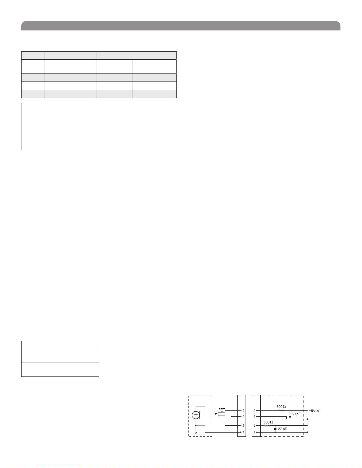
Wiring for TA4F:
MICROPHONE
ELEMENT
TA4F
Connector
TA4M
Connector
MW1 MIC JACK BOARD
Active Load
Audio
Ground
NOTE: LAVALIER MIC TIES PINS 3 AND 4 TOGETHER—GUITAR CABLE DOES NOT.
17
Page 18
Shure UHF-R® MW Wireless
Inputs and Outputs
MW1 Transmitter Audio Input
Connector: 4-Pin male mini connector (TA4M)
Input Configuration: Unbalanced, active
Maximum Input
Level:
(1 kHz, 1% THD)
TA4M Connector Pin
Assignments:
MW2 Transmitter Audio Input
Input Configuration:
Actual Impedance:
Maximum Input Level:
1 kHz, 1% THD
MW1 Transmitter RF Output
Connector:
Actual Impedance:
Pin Assignments:
RF Distribution Ports
Connector Type
Bias Voltage
NOTE: The RF distribution circuitry is activated only if connected to an RF input that
has 12 Vdc bias.
Each UR4+ RF antenna input port provides 12 Vdc bias @ 150 mA. The 12V dc
bias is present only when the UR4+ receiver is powered on. Therefore, if a cascaded
UR4+ Receiver is powered off, the RF signal will not appear in the UR4+ receivers
that follow the powered-off receiver.
+10 dBu (sensitivity 0 dB)
+20 dBu (sensitivity –10 dB)
Pin 1: Ground
Pin 2: +5 Vdc bias
Pin 3: Audio, 200 kΩ
Pin 4: Tied through active load (on main
board) to Ground.
(On instrument adapter cable, Pin 4 floats)
Unbalanced, active
>1 MΩ
+4.8 dBu
SMA
50 Ω
Shell = Ground
Center = Signal
RF IN RF OUT
BNC BNC
12 Vdc @ 150 mA
maximum
N/A
Receiver Input
Antenna Power
Connector Type:
Actual Impedance:
Nominal Input Level:
Maximum Input
BNC IEC
50 Ω
–95 to –30 dBm 100-240 VAC,50/60 Hz
–20 dBm 240 VAC, + 10%,
Level:
Pin Assignments:
Bias Voltage*
* For remote antenna amplifiers
Shell = Ground
Center = Signal
12 Vdc @ 150 mA
maximum
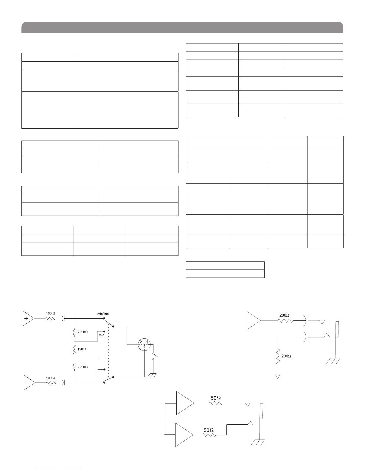
Receiver Audio Output
Monitor (1/4”
Headphone)
Output
Configuration:
Actual
Unbalanced
mono, 1/4 inch
50
Ω 200 Ω 200 Ω (active
Impedance:
Maximum
1 Watt @ 63
Output Level:
Pin
Assignments:
Tip = Hot
Ring = Hot
Sleeve = Gnd
Phantom Power
No Yes Yes
Protection:
Computer/Network Interface
Ethernet
RJ45
-
50/60 Hz
IEC Standard
N/A
1/4” Phone XLR
Impedance
Balanced
Electrically
Balanced
balanced)
(150 Ω mic)
Ω +18 dBu +24 dBu
(–6 dBu mic)
with 100 Hz
modulating
tone
Tip = Hot
Ring = no signal
Sleeve = Gnd
1 = Ground
2 = Audio +
3 = Audio –
XLR
Switch
GND
Lift
1/4" Monitor/headphone
18
1/4" Phone
Page 19

English
Replacement Parts and Accessories
Furnished Accessories
Microphone Stand Adapter (MW2)
Threaded locking Adapter (with TA4F), MW1
Zipper Bag (MW1)
Zipper Bag (MW2)
Antenna Extension Cables (2)
RF Distribution Cables (2)
Antenna (MW1) 740-865 MHz
Antenna (MW1) 925-952 MHz
Two Antennas (MW4) Band Dependent (see table)
Transmitter Carrying Case
WA371
WA340
26A13
26A14
95B9023
95N2035
UA730
UA740
UA820
95C9053
Optional Accessories
SM58 Head with Grille
SM86 Head with Grille
BETA 58 Head with Grille
BETA 87A Head with Grille
BETA 87C Head with Grille
SM87A Head with Grille
KSM9/SL Head with Grille
KSM9HS Head with Grille (Champagne, Condenser)
KSM9/BK Head with Grille
KSM9HS Head with Grille (Black, Condenser)
Matte Silver Grille (SM58)
Matte Silver Grille (SM86)
Matte Silver Grille (BETA 58)
Black Grille (SM87)
Matte Silver Grille (BETA 87A)
Matte Silver Grille (BETA 87C)
Black Grille (BETA 58)
Black Grille (BETA 87A/BETA 87C)
Champagne Grille (KSM9/SL)
Black Grille (KSM9/BK)
Popper Stopper Windscreen
Bodypack Pouch (Black), MW1
Bodypack Pouch (White), MW1
Belt Clip
Black Modular Mute Switch
Champagne Modular Mute Switch
Mute Switch for Bodypack
Mute Switch for 2 Bodypacks
RPW112
RPW114
RPW118
RPW120
RPW122
RPW116
RPW180
RPW182
RPW184
RPW186
RK143G
RPM266
RK265G
RK214G
RK312
RK312
RK323G
RK324G
RPM260
RPM264
A85WS
WA580B
WA580W
44A8031
UAMS/BK
UAMS/SL
WA661
WA662
Antenna Combiners and Accessories
• Antennas and receivers must be from the same frequency band.
• The supplied 1/2 wave antennas can be remotely mounted or mounted directly to the UA845.
• Antennas and cables for use with the UA845 can also be used with stand-alone UHF-RMW receivers.
Passive Antenna Splitter Kit
Antenna/Power Distribution (470-952 MHz)
1/2-Wave Onmidirectional Antenna, (470–1100 MHz)
In-line RF Filter (779-788 MHz)
In-line RF Filter (779-810 MHz)
In-line RF Filter (797-810 MHz)
In-line RF Filter (925-932 MHz)
In-line RF Amplifier (925-932 MHz)
Active Antenna (470-698 MHz)
Active Antenna (470-790 MHz)
Active Antenna (470-900 MHz)
Active Antenna (925-952 MHz)
Omni-Directional 1/2 Wave Antenna (944-1000 MHz)
UA221
UA845-SWB
UA860SWB
UAPF-A2
UAPF-ABJ
UAPF-A4B
UAPF-X2
UA830X2
UA874US
UA874E
UA874WB
UA874X
UA820X
19
Page 20

Shure UHF-R® MW Wireless
Architects' and Engineers' Specifications
The wireless system shall operate in the UHF band between 779-932 MHz, with the specific range being dependent on the user's
locale. The system shall include the option of changing the operating frequency in order to avoid RF interference, enabling up to 39
systems to operate simultaneously in the same location. Preconfigured group, channel and frequency setups shall be available to
ensure that multiple systems in use do not interfere with one another.
All transmitters shall be powered by 2 AA batteries and shall have a power on/off switch. The bodypack will have an LED indicating that
power is on. Available transmitters shall include: a body pack for use with electric guitars, basses, and other electric instruments, and
a handheld microphone for vocals. The transmitters shall have a DC/DC converter to ensure consistent performance, even if battery
voltages change.
The receiver shall have a user-programmable, menu-driven LCD showing group, channel, frequency, name, squelch level, and locked/
unlocked status. The system shall use technology such as MARCAD‚ signal combining circuitry to improve reception, minimize signal
dropouts, and achieve the best possible signal-to-noise ratio. An equalizer, tone key squelch, and noise squelch circuitry shall be built
into the system to provide optimal sound quality and minimize unwanted noise. The receiver shall include dual RF meters (one for each
antenna), an audio level meter, and a Networking Interface connector for computer control and monitoring. The receiver shall have a
volume control and an adjustable noise squelch control.
The system shall be the Shure UHF-R
Emission Designator
120KF3E
The “EU Declaration of Conformity” can be obtained from Shure Inc. or any of its European representatives. For contact information
please visit www.shure.com
MW Wireless.
Note:
To fully interact with the Receiver, it is recommended to upgrade the UR4 firmware to 1.50 or higher and Shure Wireless Workbench to 5.0.1 or higher
LICENSING INFORMATION
Licensing: A ministerial license to operate this equipment may be required in certain areas. Consult your national authority for possible
requirements.
Changes or modifications not expressly approved by Shure Incorporated could void your authority to operate the equipment. Licensing
of Shure wireless microphone equipment is the user’s responsibility, and licensability depends on the user’s classification and
application, and on the selected frequency.
Shure strongly urges the user to contact the appropriate telecommunications authority concerning proper licensing, and before
choosing and ordering frequencies.
INFORMATION TO USER
This equipment has been tested and found to comply with the limits for a Class B digital device, pursuant to Part 15 of the FCC Rules.
These limits are designed to provide reasonable protection against harmful interference in a residential installation. This equipment
generates, uses and can radiate radio frequency energy and, if not installed and used in accordance with the instructions, may cause
harmful interference to radio communications. However, there is no guarantee that interference will not occur in a particular installation.
If this equipment does cause harmful interference to radio or television reception, which can be determined by turning the equipment
off and on, the user is encouraged to try to correct the interference by one or more of the following measures:
• Relocate the receiving antenna.
• Increase the separation between the equipment and receiver.
• Connect the equipment into an outlet on a circuit different from that to which the receiver is connected.
• Consult the dealer.
Note: EMC conformance testing is based on the use of supplied and recommended cable types. The use of other cable types may
degrade EMC performance.
Changes or modifications not expressly approved by the manufacturer could void the user’s authority to operate the
equipment.
20
Page 21

日本語
目 次
機能概要 ................................................................................................................................................................................................................................................................................22
システムの構成 ....................................................................................................................................................................................................................................................................23
受信機のコントロールとコネクター ..................................................................................................................................................................................................................................24
受信機 LCD インターフェース ..........................................................................................................................................................................................................................................25
複数受信機のRF分配ポートへの接続 .............................................................................................................................................................................................................................26
受信機 LCD インターフェース ..........................................................................................................................................................................................................................................27
受信機のネットワーク ..........................................................................................................................................................................................................................................................28
ハンドヘルド型およびボディパック型送信機のコントロールとコネクター .............................................................................................................................................................29
送信機 LCD インターフェース ..........................................................................................................................................................................................................................................29
送信機の電池.........................................................................................................................................................................................................................................................................29
送信機のパラメータ ............................................................................................................................................................................................................................................................30
送信機ゲインの設定 ............................................................................................................................................................................................................................................................30
RF 安全モード .......................................................................................................................................................................................................................................................................30
送信機自動同期 ..................................................................................................................................................................................................................................................................31
トラブルシューティング ........................................................................................................................................................................................................................................................32
仕 様 .......................................................................................................................................................................................................................................................................................33
交換パーツおよびアクセサリー .........................................................................................................................................................................................................................................35
周波数帯域. ............................................................................................................................................................................................................................................................................37
21
Page 22

Shure UHF-R® MW ワイヤレス
機能概要
UHF-R®MW ワイヤレスマイクロホンシステムは最新のワイヤレス技術を採用しているため、抜群にクリアな音質が得られ、信頼性 が高く、丈夫です。 ワイヤレスマイ
クロホンシステムを複数必要とするプロ用途向けの高度な機能を搭載し、しかもセットアップも 使用も簡単です。
周波数帯域の選択
Shure は、さまざまな国や地域の行政規制に合わせて周波数帯域を選択できるワイヤレスシステムを提供します。 国や地域の規制 は、さまざまなワイヤレス装置同
士の無線周波 (RF) 干渉を制限し、テレビや緊急放送などの地域の公共通信チャンネルとの混信を 防ぐためのものです。
このシステムの周波数帯域範囲は、受信機と送信機の前面に記載されています (例えば「MJBX 806 ~ 810 MHz 」など) 。 お使いの地域での周波数帯域に関する
情報は、代理店にご相談いただくか、または Shure までお問い合わせください。 詳しい情報 は Shure のウェブサイト (www.shure.com) にも掲載されています。
グループとチャンネル
ワイヤレスシステムで音声を伝達するには、送信機と受信機を同じ無線周波数、すなわちチャンネルに設定しなければなりません。 各マイクロホンは別のチャンネ
ルにしなければならないため、幅広い範囲からチャンネルを選択することにより、より多くのマイ クロホンを同時に使用できるようになります。 また、オープンチャンネ
ル— テレビ放送や電子機器、他のワイヤレスシステムから の干渉を受けないチャンネル— の選択範囲も広がります。 グループとは、受信可能なチャンネルを複数
選択したものです。 複数のワイヤレスマイクロホンは、同じグループ内のチャンネルに 設定すると、うまく作動します。
周波数自動選択
それぞれの設置条件において、無線周波数環境をスキャンし最適のグループおよびチャンネル設定を見つけ出す機能として、次の
も の が ありま す 。
• グループスキャン—オープンチャンネルがいちばん多いグループを見つけ出し、ネットワークされた受信機全部をこのグループ内
の チャン ネ ル に 設 定し ます 。
• チャンネルスキャン—現在選択されているグループ内で最初のオープンチャンネルを見つけ出し、このチャンネルに受信機を設定
します。
この機能の使用方法については、27 ページの手順に従ってください。
送信機自動同期
この機能は、グループおよびチャンネル設定を、受信機から送信機へ自動的に転送するものです。 受信機上にある他の送信機設定を プログラムして、その設定を
転送することもできます。31 ページをご参照ください。
イン ターフェー ス の ロック
この機能は、ユーザーが設定を変更できないように、受信機と送信機をロックするものです。 送信機の電源スイッチも使用不能にす ることができます。こうすると、パ
フォーマンス中に電源スイッチが誤って切り換わった場合にも、送信機はオンのままになります。
音声ゲイン構成
この設定で、システム全体の音声ゲインを調整することができます:
• 感度 ( ボディパックのみ) : ボディパックの送信機入力側で、25 dB の範囲でゲインを調整。
• 送信機ゲイン: 送信機内の音声ゲインを 30 dB の範囲で調整 ( 受信機側の音声レベルに影響。Audio LED で表示される)。
• 出力レベル: 受信機出力側で 32 dB の減衰と、ミュート設定。
• MIC/LINE 出力レベル切換スイッチ: 受信機 XLR 出力の音声レベル・マッチングの -30 dB パッド。
ネ ット ワ ー ク
受信機はそれぞれ、イーサネットネットワークを介して他の受信機と接続するため、裏側に RJ-45 ポートがあります。 受信機をネッ トワーク接続することにより、グルー
プスキャンのコマンド1 回だけで全受信機のチャンネル設定を自動的に行うことができます。 Shure ワイヤレスワークベンチ PC ソフトウェアを使用して、ネットワーク
接続されている受信機すべてを制御・監視することもで きます。
RF分配ポート
RF分配ポートを使用すると、一組のアンテナからの信号を最大10台の同一周波数帯の受信機で共有することができます。RF分配ポートを使うことで、アンテナ
分配器や分配アンプは不要となります。アクティブ電気回路により挿入損失が最小化され、信号の質を保ちます。入力フィルターは、信号への帯域外の干渉を排
除します。分配回路は、増設受信機をRF分配ポートに接続したときにのみ動作します。未使用時にはポート回路はバイパスされますので、受信機は単独のユニ
ットとして使 用することができます。
Shure ワイヤレスワークベンチソフトウェア
添付 CD に入っている Shure ワイヤレスワークベンチソフトウェアには、複数のワイヤレスシステムをインストールおよび管理す るために役立つさまざまなツールが
含まれています。 コンピューターにこのソフトウェアをインストールし、受信機のネットワーク に接続するだけで、ネットワーク全体の受信機および送信機を監視・制御
できます。( ネットワークに関する詳細は 28 ページをご 参照ください。) このワイヤレスワークベンチソフトウェアの使用方法は、ソフトウェアをインストールした後、オ
ンラインヘルプファイルをご覧 ください。
22
Page 23

システムの構成
全てのシステムには以下の機器が同梱されています:
日本語
MW4D+ 受信機
1/2 波長アンテナ 2 本
アンテナホールプラグ 2 本 ラックマウント用ネジ
(ワッシャー付き) 4 本
単三電池
アンテナケーブル 2 本
IEC 電源ケーブル
IEC 電源延長ケーブル
イー サ ネ ット ネット ワ ー ク ケ ー ブ ル
( 強化プラグ付き)
RF分配ケーブル2本
Shure ワイヤレスワークベンチ
ソフト ウェア
送信機キャリングケース
ハンドヘルドシステムには以下の機器が同梱さ れています:
マイクロホン・ヘッド (SM58®、SM86、Beta 58A®、
Beta 87A™、Beta 87C™ 、KSM9/BK, KSM9SL のいずれか 1 つ)
MW2 ハンドヘルド型送信機
マ イクロホ ン クリッ プ
ボディパックシステムには以下の機器が同梱されています
ねじ型 TA4F アダプター
MW1 ボディパック型送信機
23
Page 24

Shure UHF-R® MW ワイヤレス
受信機のコントロールとコネクター
17
MW4D+
Wireless Receiver
with Audio Reference
Companding
sync
RF Audio
OL
A B
XX YYY-ZZZ MHz Navigate
2 4 5
RF Audio
OL
A B
XX YYY-ZZZ MHz Navigate
6
ENTER
EXIT
OFF
push
Monitor Clip
Monitor
7
8
Control
push
POWER
RF B out
antenna B in
12.7V out
150mA
9
10
11
balanced low Z
line
mic
12 13 14 15
18
同期赤外線 (IR) ポート: グループやチャンネル、その他の
設定を送信機に転送します。 31 ページをご参照ください。
スケルチ LED :
• 青 ( オン) = 送信信号を検知。
• オフ = 受信信号なし、または受信状態が悪いあるいはトー ンキーが
ないため信号がスケルチされている。
注: 青の LED が最低1 つ点灯していないと、受信機は 音声を出
力しません。
RF LED : 各アンテナおよびダイバーシティ状態において、
送信機からの RF 信号強度を示します。
• アンバー = 正常
• 赤= オーバーロード(-25 dBm 以上)
4 Audio LED : 送信機からの音声信号強度を示します。
• 緑 = 信号が存在
• 黄色 = 通常のピーク
• 赤 = オーバーロード
このレベルを修正するには、送信機ゲインを調整します。
5 受信機の周波数帯域の名称と範囲を示します。
LCD インターフェース: これによりフロントパネルで受信
機を簡単にプログラムすることができます ( 詳細は次ペー
ジをご参照ください)。
7 モニタ— : ヘッドホン用の 6.35mm 出力ジャックと音量
つ ま み 。
• モニタークリップ LED は、ヘッドホン音声がクリップしていることを示
します。
• デュアルモデル: つまみを押すと受信機1から受信機2に切り替わり
ます。
receiver outputs
200Ω
lift
GND
networking
balanced low Z
network
activity
line
ethernet
mic
RJ-45
16
receiver outputs
200Ω
lift
GND
antenna A in
12.7V out
150mA
11
RF A out
18
電源スイッチ: 受信機のオン/ オフを切り替えます。
AC 主電源入力、IEC コネクター: AC100 ~ 240 V。
AC 電源パススルー ( アンスイッチド)。IEC延長ケーブルを使用して
最大5台までのUR4+受信機を1つのAC電源に接続できます。
ダイバーシティアンテナ入力 A ・ B.
注: アンテナ入力は直流バイアスがかかっています。 35 ページ記
載の
アン テ ナコン バ イナー お よび アク セ サリー だ け を 使 用
してください。 アンテナスプリッターその他の製品の
種類によっては、直流電流がショートし、受信機が破損す
る 場 合 が ありま す 。
Mic/Line 切換スイッチ: 出力レベルが30dB変わります (XLR 出力
のみ) 。
電子バランス XLR 出力ジャック
Lift/GND 切換スイッチ: XLR コネクターのピン 1 をアースから切り
離します ( デフォルト = GND)。
インピーダンスバランスの 6.35mm 出力ジャック (200Ω)
イーサネットネットワークインターフェース用のRJ-45 ジャック。 レギュラ
ータイプ、および強化型 RJ-45 プラグに 適合。
温度作動ファンにより、高温環境でも最高のパフォーマンス
を保 証します。 必要に応じてファンスクリーンに付いてい
るホコリを取り除いてきれいにしてください 。
RF分配ポートによりRF信号を1台の受信機から次の受信機へと受
け渡しすることで、最大で10台の受信機が1組のアンテナを共有す
ることがで きます。
24
Page 25

受信機 LCD インターフェース
日本語
メニューアクセ ス
SHURE
524-025 MHz TV: 32
G: 3 Ch: 1 Out: -0dB
+12 dB
+
選 択したいメニュー アイテムの 隣 に
ある Navigate キーを押します。
Radio
Audio
Util
Sync
F, P, FP
Hi
変更の承認
パラメー タを 変 更 すると 、ENTER ボ タン が 点 滅 します 。
このボ タン を 押 すとそ の 値 に 設 定されます 。
送信機のステータス表示
点線より下側はすべて、送信機の設定を
表します ( メインのタイトル画面のみ)。
Exit/Cancel
Exit ボ タ ン を 押 す と 、変 更 は キ ャ ン セ ル さ
れ 、前 の メ ニ ュ ー に 戻 り ま す 。
受信機のパラメータ
下記の手順に従って、LCD インターフェースでパラメータを設定します。
注: パラメータを調整した後は、点滅している ENTER ボタンを押して変更を承認しなければなりません。
グループとチャンネル
メ ニ ュ ー: Radio
• Control ホイール を 押して 、カ ー ソ ル を グ ル ー プ (G) また はチャン
ネル (Ch) パ ラメー タまで 動 かしま す 。
• パラメー タを 変 更 するに は 、Control ホイールを回しま す。
周波数
メ ニ ュ ー: Radio
• Control ホイール を 押して 、カーソルを整数値 (524.025 MHz)
または小数値 (524. 025) まで動かし ます。
• 値を変更するには 、Control ホ イー ル を 回しま す 。
送信機自動同期
メ ニ ュ ー: Sync
• 31 ページをご参照ください。
受信機名
メ ニ ュ ー: Util
• 文字を変更するには、Control ホ イール を 回します。
• 次の文字に移動するには、Control ホ イー ル を 押します 。
出力レベル
メ ニ ュ ー: Audio
この設定では、XLR および 6.35mm 音声出力ジャックの信
号 レ ベ ル を 調 整 し ま す 。
• dB 単位の相対レベルを変更するには、Control ホ イー ル を 回しま
す。 (0 dB ~ -32 dB)。
• ホイールをいちばん下まで回すと、出力がミュートになりま す。
カーソ ル の 操 作
カーソ ル を 次 の 項 目に 動 か すには 、
Control ホイール を 押します。
パラメー タの 値を 変 更 す るには 、
Control ホイール を 回します。
スケルチ
メ ニ ュ ー: Radio > Squelch
• パラメータを変更するには、Control ホイールを回しま す。
受信機のロック
受信機がロックされていると、フロントパネルでの変更はで
きません。 ただし、LCD メニューを自由に表示させて設定を
見ることはできます ( ロックをオフにすることもできます)。
メ ニ ュ ー: Util > Lock
• Control ホイールを回して、ロックのオンとオフ ((ON ま たは OFF)
を切り換えます 。
LCD 表示
メ ニ ュ ー: Util > Title
• Control ホイール を 回して 、表示させる項目を指定しま す。
• 次の項目に移動するには、Control ホ イー ル を 押します 。
LCD コントラスト
メ ニ ュ ー: Util > Contrast
• コントラストを調整するには、Control ホイールを回しま す。
トーンキー
メ ニ ュ ー: Radio > Squelch > Tonekey
トーンキースケルチは、受信機が送信機を検出していない間、出
力 を ミ ュ ー ト に し ま す 。 ト ー ン キ ー は 、特 定 の ト ラ ブ ル シ ュ ー
ティングの場合を除き、オン (On) にしておいてください 。
25
Page 26

Shure UHF-R® MW ワイヤレス
ネ ット ワ ー ク パ ラ メ ー タ
注:
• ENTER を押してネットワークパラメーターの変更を承認すると、受信
機は再起動します。
• デュアルモデル (MW4D+) では、この設定は両方の受信機に 影響し
ます ( デュアル受信機は単一のネットワーク装置とし て扱われます)。
受信機ネットワークモードの設定
メ ニ ュ ー: Util > Network
1. Control ホ イール を 押して 、カ ー ソ ル を Mode パ ラメー タに 動 か
します。
2. Control ホ イール を 回して 、 この受信機を次のいずれかの 値に設
定 し ま す:
• DHCP: 受信機を DHCP サーバーに接続する際にこの設 定を使用し
ます。
• Manual: この受信機を特定の IP アドレス、サブネットに設定するこ
とができます。
IP アドレス、サブネット
メ ニ ュ ー: Util > Network
注: この設定を変更するには、ネットワークモードが
Manual に な ってい る 必 要 が ありま す 。
1. Control ホ イール を 押して 、カ ー ソ ル を 下 記 の パ ラ メ ー タ い ず れ か
に動かします 。
• IP(IP アドレ ス )
• Sub ( サブネットマスク)
2. 値を変更するには、Control ホイールを回します。
デバイス ID
ワイヤレスワークベンチソフトウェアによって受信機の識別 を容易にします ( ネ
ットワーク上での識別には影響しません)。
メ ニ ュ ー: Util > Network
1. Control ホ イール を 押して 、カ ー ソ ル を DevID パ ラメー タに 動
かします。
2. Control ホ イール を 回して 、 値を変更してこの受信機の設 定を行
います。
カスタムグ ル ープ
この機能では、周波数グループを独自に作成することができ ます。
新規グ ループを作 成するには
メ ニ ュ ー: Radio > Custom
1. Control ホ イール を 回して 、カスタムグループ番号を選択 します
(U1, U2, U3, 等)。
2. Control ホ イール を 押して 、Channel パラメータに合 わせ、回し
てチャンネルを選択します (01、02、03、等)。
3. Control ホ イール を 押して 、 Freq パ ラ メ ー タ に 合 わ せ 、 そ の チ ャ
ンネルの周波数を選択します。
4. NEXT メニュー キー を 押して 、そのグループ内の次のチャ ンネルの
周波数選択に進みます。
複数受信機のRF分配ポートへの接続
RF分配ポートによりRF信号を1台の受信機から次の受信機へと受け渡しすることで、最大で10台の受信機が1組のアンテナを共有することができます。付属RF
分配ケーブルを使用し、図のように各受信機のポートを接続します。
注:受信機はすべて同じ周波数帯になければなりません。
アンテナB入力
最初の受信機
追加の受信機
最後の受信機
アンテナA入力
Antenna A in
RF A out
Antenna A in
RF A out
Antenna A in
RF A out
26
Page 27

日本語
周波数自動選択
チャンネ ル ス キャンおよ び グ ル ー プ ス キャン 機 能 は 、次 の 手 順 に 従 って 使 用し ま す 。
始める前に
• 使用する場所に受信機を設置し、電源を入れます。
• 受信機に接続されたミキサー装置の入力をすべてミュートします。
• 設定するシステムのボディパック型送信機やハンドヘルド型送信機はすべて、スイッチをオフにします。
• 他のワイヤレスシステムやワイヤレス装置、コンピューター、CD プレーヤー、エフェクトプロセッサー、デジタルラック装置な ど、電波干渉の原因となりうるも
のをオンにして、プレゼンテーションやパフォーマンスの最中と同様に作動させます。
シングル受信機
1. 受信機の LCD インターフェースにある Navigate キーを使 用して 、Radio > Scan > Chan Scan を選択します。
2. Control ホイールを回して、グ ループを選 択します。
3. Chan Scan. を押します。 受信機がサーチを行っていることが表示されます。 サーチが終わると、選択されたチャンネルが表示されます
4. 点 滅している ENTER ボタンを押し て、提 案され ているチャン ネル を承認します。
5. 送信機を同期します (31 ページをご参照ください)。
ネットワークされている受信機、またはデュアル受信機
ネットワークされている受信機やデュアル受信機の場合は、グループスキャン機能を利用して、すべての受信機に対して同時に、グループ設定およびチャンネル設定
を行うことができます( ネットワークに関する手順は28 ページをご参照ください)。
任意の受信機からグループスキャンを行うには
1. 受信機の LCD インターフェースにある Navigate キーを使 用して 、Radio > Scan> Group Scan を選択します。 受信機がサーチを行っている
ことが表示されます (Scan In Progress)。 サーチが終わると、最もオープンチャンネルの多いグ ループが表示されます。
2. 必 要に 応じ、Control ホイールを回してグ ループを 変 更します。 各 グ ループ の オープンチャンネル の 数 が 表 示され ます 。
3. 点 滅している ENTER ボタンを押して、すべての受信機をそのグループのオープンチャンネルに設定します。
注: グループスキャン機能は、同じ周波数帯域にある受信機に対してのみ有効です。
複数の受信機ーネットワークされていない場合
受信機がネットワークされていない場合 ( または異なる帯域にある場合) は、グループスキャンでグループ設定やチャンネル設定を
自動的に行うことはできません。 ただし、グループスキャン機能を利用して、オープンチャンネルが最も多いグループを見つけ、
チャンネ ル ス キャン 機 能 を利 用 し て そ のグ ル ープ 内 の オープン チャンネ ル を 見 つけ 出 すことが できま す 。
オープンチャン ネルが最も多いグループ を見つけ出すには
ネットワークされている受信機の手順 ( 上記) に従ってグループスキャンを行います。 ここで、選択されたグループをメモに記録してから、点滅している ENTER ボタ
ンを 押して 承認します。
受信機をそのグループのオープンチャンネルに設定するには
受信機1 台の手順 ( 上記) に従って、残りの受信機のチャンネルスキャンを行います。 チャンネルスキャンを行う前に、各受信機に
ついて 、同じグループを 確実に選択し てください。
重要: 最初の受信機のチャンネル設定を行ったらすぐに、その受信機について送信機の同期を行い、電源をオンにしておきま す。 これにより、次の受
信機でのチャンネルスキャンの際、そのチャンネル使用が検知されます。 そうしないと、すべての受 信機が同一のオープンチャンネルに設定されてしま
います。
27
Page 28

Shure UHF-R® MW ワイヤレス
受信機のネットワーク
基本的なネットワーク
D H C P サービス 付きのイーサネットルータに受 信機を接続します。 イーサネット
のスイッチを使用して大規模な設置用にネットワークを拡大できます
受信機のデフォルトのネットワーク設定を使用
(Util > Network > Mode = DHCP)。
コンピ ュー タ ー に よ る ネットワー ク ア ク セ ス
ワイヤレスワークベンチソフトウェアを使用する場合は、コンピューターをネッ トワークに接続して
受信機同梱のCDにあるソフトウェアをインストールします。 コ ンピューターにDHCPの設定が可
能であることを確認します(コントロールパネルから、ネットワーク接 続をクリックします。 ローカ
ルエリア接続をダブルクリックします。 インター ネットプロトコル (TCP/IP) を選択し、プロパティ
をクリックします。 IP アドレ ス自動取得およびDNSサーバーアドレス自動取得を選択してOK を
ク リ ッ ク し ま す )。
注: コンピューター の セキュリティソフトウェアやファイアウォー ル の 設 定 によって は
受信機接続を妨げる場合があります。 ファイアウォールソフトウェアを使用している
場合は、ポート2201 の接続を許可してください。
Ethernet
DHCP 付きルータ
DHCP 付きルータ
スイッチ
コンピューター
(オプション)
コンピューター
(オプション)
スイッチ
スタティックIP アドレス
受信機はスタティックIP アドレスもサポートします。 使用するIP アドレスを(Util>Network>Mode = Manual) で 設 定 し ま す 。“ ネ ッ ト ワ ー ク パ
ラメータ” on page 26 を参照してください。
注: デュアル受信機では単一の IP アドレスを使用します。これは、いずれかの LCD インターフェースで設定することができます。
28
Page 29

ハンドヘルド型およびボディパック型送信機のコントロールとコネクター
日本語
交換可能マイクロホンヘッド(図は BETA 87A)
LCD パネル。
電 源 ス イッチ 。
LCD インターフェース用のコントロールボタン。
赤外線(IR) ポート。31 ページをご参照ください。
送信機 LCD インターフェース
524.025MHz
exit キー。 左に移動、または
変更を保存せずに終了。
上矢印キー。 上にスクロール、
または値を増加。
電 池コン パート メント 。
フレ キシブ ル アン テ ナ 。
電源 LED。
4 ピンマイクロホン入力ジャック。
リ バ ー シ ブ ル ベ ル トクリップ 。
enter キー。 押し てパラメーターを選 択 し 、選
択した 値を 承 認する。
Main Menu
下矢印キー。 下にスクロール、
または値を減少。
送信機の電池
送信機には標準の単三電池を使用します。 送信機の電源をオフにしてから電池を交換してください。
下の図のように、送信機 LCD 上に表示される電池残量ゲージで、残りの電池寿命がわかります。
送信機の表示画面 およその残量時間
( ア ル カリ電 池 )
MW1/MW2 電池寿命
7.5 ~ 9.5
5.75 ~ 7.5
4 ~ 5.75
2 ~ 4
15 分~ 2 時間
29
Page 30

Shure UHF-R® MW ワイヤレス
送信機のパラメータ
メインメニューで ENTER を押して、下記のパラメータにアクセスします:
グ ループ ( G) およびチャンネル (Ch)。 受信機の設定と一致していなければなりません。
G:34 Ch:21
524.025MHZ
Gain +20dB
SHURE INC.
次の組み合わせキーを使って、その他の機能やパラメーターにアクセスすることがで
き ま す:
周波数(MHz)。 手動での周波数選択は 0.125 MHz 刻みです。
ゲ イン ( Gain)。 音声レベルを-10 dB ~ +20 dB の範囲で調整します。
感度 (Sens) ( ボディパックのみ)。
音声入力を +15 dB、0 dB、およびギターに適した-10 dB のいずれかに設定します。
名称表示。 12 桁の ASCII 文字。
ロック イン ジ ケーター
ホー ルド タップ
ホー ルド タップ
ホー ルド タップ
ホー ルド タップ
LCD パネル
LCD パネルを変更します。
周波数ロック
設定を切り換えます。 ロックされているときは、周波数は変更できず、
送信機同期の際に周波数設定は上書きされません。
電 源 ロック
電 源 ロ ッ ク を 切 り 換 え ま す 。 ロ ッ ク さ れ て い る と き は 、電 源 ス イ ッ チ
を操作しても送信機の電源はオフになりません。
RF 電源レベル設定
矢印キーを使用して、標準出力 (10 mW) あるいは低出力 (2 mW) のいずれかを選択します。 電池を
節約したい場合や、受信機側の RF オーバーロードを防ぎたい場合は標準出力設定を使用してくださ い。
送信機ゲインの設定
使用中に受信機の Audio LED のピークが黄色の範囲になるように、送信機のゲインと入力感度を調整してください。 ボディパック
型送信機では、別の楽器やマイクに入力を接続した際、異なる音声レベルを補償するよう、感度設定を変更することができます。
ゲインを調整するには、送信機をオンにして enter ボタンを押します。 Gain パ ラメー タまた は Sens パラメータ ( ボディパッ
ク型のみ) をス クロール して、Enter をもう一度押します。 矢印キーを使用して設定値を調整し、 enter を押して保存します (Exit
を押すと保存せず、キャンセルされます)。
524.025MHZ
電源ロック
周波数ロック
RF 安全モード
この特殊機能は、RF 電波の発信を一時的に停止するものです。 これにより、 他の送信機が使用しているチャンネルに誤って割り込む
ことなく、送信機の周波数設定変更を行うことができます。
1. 送 信機をオフにします。
2. exit キーを押したままで送信機の電源をオンにします ( ハンドヘルドの場合は、ハンドルの電池カバーを外す必要があります)。 装置が RF 安全モードにな
っているときは、LCD が点滅します。
3. ふつう通りにグループやチャンネルの設定変更を行っても、送信機は電波を発信しません。
4. 送信機の電源を一度切ってからオンにすると、RF 安全モードが終了します。
30
Page 31

送信機自動同期
この機能は、選択した受信機に合うように、ボディパック型またはハンドヘルド型の送信機のグループ設定やチャンネル設定を自
動的に更新するものです。
送信機の同期を行うには
1. 送信機の電池カバーを開け、赤外線(IR) ポートを露出させます。
2. IR ポートを受信機に向けて露出した状態で、受信機の LCD インターフェースで Sync > Sync を選 択します。
受信機の表示画面に、同期がうまく終了したかどうかが表示されます。 同期に失敗した場合は、送信機の IR ポートが露出している
ことと、受信機の IR ポートに直接向いていることを確認してから、もう一度試みてください。
注: 電池カバーを閉めてから、他の送信機の同期を行ってください。
®
MW4D+
Wireless Receiver
with Audio Reference
Companding
Audio NavigateRF
OL OL
sync
Audio NavigateRF
Control
ENTER
EXIT
sync
Monitor Clip
日本語
Monitor
1
2
push
Power
他の送信機の設定を転送するには
オプションとして、同期を実行する際に、受信機から他の送信機の設定を転送することができます。 下記の手順を使用します:
1. 受信機の LCD インターフェースで Sync > Setup を選 択します 。
2. Control ホイールを回して、パラメータ設定 を変更します。
3. 次 の パ ラメー タに 移 動 するに は 、Control ホイール を 押しま す 。
4. 点 滅している ENTER ボタンを押し て設 定 を保 存します 。
受信機に設定した送信機設定は、後で同期を行うために保持されます。
注: 同期の際に設定を送信したくない場合は、パラメータを No Change に設定します。
使用できる設定
Sync > Setup メニューでは下記の設定が使用できます:
• 感度 (Sens) ( ボディパックのみ)。
• ゲ イン ( Gain)
• RF 出力 (Pwr)
• 電源・周波数のロック (Lock) 。こ れ に は 次 の 値 が あ り ま す :
電源ロックのみ: (Pwr Only)
周波数ロックのみ: (Freq only)
両 方: ( Freq and Pwr)
ど ちら もロック せ ず: ( Unlocked)
• カスタムグ ループ ( CG):
オン (ON): 同期中にカスタムグループを送信機に送る
オフ ( OFF): カスタムグループを送らない(同期時間の短縮)
31
Page 32

Shure UHF-R® MW ワイヤレス
トラブ ルシューティング
問 題 解決策
音が聞こえない 電源、ケーブル、RF
音 が 小 さ い 、ま た は 歪 ん で い る ゲ イン
レ ン ジ が 乏 し い 、不 快 な ノ イ ズ バ ー ス ト が あ る 、音 の 欠 落 が あ る RF
送信機の電源をオフにできない、周波数設定を変更できない、受信機をプログラムできない イン ター フェー ス の ロック
過剰なうなりや雑音 グ ラ ンドリフト ス イッチ
電 源
送信機と受信機には、十分な電圧があるようにしてください。受信機は最低 AC
90 V が必要です。 送信機は電池インジケーターをチェックして、必要に応じ電池
を 交 換 し てください 。
ゲ イン
送信機のゲインと感度設定を調整 (30ページ をご参照ください)、または受信機
の出力レベルを調整 (25ページをご参照ください)、あるいは受信機裏側の mic/
line スイッチを切り換えてください。
ケーブ ル
ケ ーブ ル とコネクター が す べ て きち ん と 接 続 さ れ て い る か チェッ クし て く ださい 。
アースを外す
受信機の XLR 出力のピン1にあるアースを外すと、音声信号のうなりや雑音がな
くなることがあります。 XLR コネクターを使用している場合は、受信機の GND/
LIFT ス イッ チ を LIFTにし て ください 。
イン ターフェー ス の ロック
送信機と受信機はどちらも、誤って設定を変えてしまうのを防ぐため、ロックでき
るようになっています。送信機では、LCD に錠の記号が表示されていないか確
認し、30ページ に説明されているように組み合わせキーを使用してロックを解除
し てください 。
受信機のインターフェースロックを解除するには、25ページをご参照ください。
レンジ の拡 大
送信機が受信機アンテナから 6~60 m 以上の距離にある場合は、下記のいず
れかを行ってレンジを拡大することができます:
• 干渉を減らす (上記をご参照ください)。
• 送信機RF 出力レベルを増加 (30ページ をご参照ください)。
• アクティブ 指 向 性 アンテ ナやアン テナ分 配シ ステム などの アンテナ 付
属品を使用して、RF レンジを増加 (35ページ をご参照ください)。
無線周波数 (RF)
RF LED の使用
青の RF LED のどちらも点灯していない場合は、受信機が送信機の存在を検出
し て い な い こ と を 意 味 し ま す 。
アンバーの RF LED は、受信している信号の量を表します。 この信号は送信機
からのものも、 またテレビ放送などの干渉電波源からのものも含まれます。 送
信機をオフにします。 アンバーのRF LED が1つまたは複数点灯し続けている場
合は、そのチャンネルには干渉電波が多すぎることを意味します。別のチャンネ
ル を 試して み てください 。
赤の RF LED は、RF オーバーロードを示します。 複数のシステムを同時に使用
しているのでない限り、これはふつう問題とはなりません。複数 のシステムを同
時に使用する場合は、システム間に干渉が生じることがあります。
RF オーバーロードをなくす
受信機側に赤の RF LED が点灯したら、送信機の RF 出力レベルを下げるか (30ペ
ージ をご参照ください)、または送信機を受信機から離します (最低 6m)。 アクティ
ブアンテ ナを使 用している場合は、アンテナまたはアンプのゲ インを 下 げます。
互換性
• 送信機同期を行うか、または送信機と受信機が同じグループおよびチ
ャンネルに設 定されていることを確 認してください。
• 送信機と受信機のラベルを見て、同じ帯域 (H4、J5、L3、等) にあること
を 確 認 し てください 。
干 渉を減らす
• 別 の チ ャン ネ ル を使 用 す る か 、グ ルー プ ま た は チ ャン ネ ル の 自 動スキャ
ンを実行してください (27ページをご参照ください)。
• 複数システムの場合は、すべてのシステムが同じグループのチャンネ
ルに設定されていることを確認してください (別の帯域にあるシステム
は、必ずしも同じグループに設定する必要はありません)。
• 送信機と受信機アンテナの間に遮蔽物のないようにしておきます。
• 受信機アンテナは、金属物や RF 干渉電波源 (CD プレーヤーやコンピ
ューター、デジタル効果、ネットワークスイッチ、ネットワークケーブル、
パーソナルステレオモニター (PSM)ワイヤレスシステムなど) から離し
てください 。
• RF オーバーロードをなくします。
32
Page 33

日本語
仕 様
周波数帯域および送信機出力
帯 域 範 囲 送信機出力 (mW)
ハンドヘ ルド 型
MW2
X2
MA24
MAJBX
本無線機器は、業務用の音楽エンターテイメントおよび同様の用途に使用するためのも
のです。
本無線機器はご使用の地域で認可されていない周波数で操作できる場合があります。
国内当局にお問い合わせになり、ワイヤレスマイクロホン製品の認可周波数と RF 出力
レベルの情報をご確認ください。
送受信周波数帯域
925-932 MHz
779-788 / 797-806 MHz
806-810 MHz 2 / 10 2 / 10
2 / 10 2 / 10
2 / 10 2 / 10
注:
779-932 MHz (地域により異なる)
作動範囲
MW1, MW2: 通常条件下で 150 m。
ライン•オブ•サイト500 m、屋外専用、単一システム用
注: 実際の作動範囲は、RF信号の吸収や反射、妨害により左右
されます。
周波数特性
40 – 18,000 Hz, (+1 dB, –3 dB).
注: システム全体の周波数特性は使用マイクロホンにより変わります。
ゲイン調整範囲
MW1: -20 ~ +35 dB
ギターには-10 dB推奨
MW2: -10 ~ +20 dB
変調
FM (最大 45 kHz の偏差)、プリエンファシスおよびディエンファシス処理付き
のコンパンダーシステム。
RF 出力
最大2mWまたは10mW
ダ イナ ミックレン ジ
>105 dB、A ウェイト
イメージ抑圧比
>110 dB (標準)
RF 感度
MW4D+
-107 dBm (標準)
12 dB SINAD
-102 dBm (標準)
30 dB SINAD
スプリアス抑圧比
>90 dB (標準)
超静音 (45 kHz偏差)
>100 dB、A ウェイト
ボ ディパック 型
MW1
信号極性
マイクロホンのダイヤフラムへの正の圧力 (または WA302フォンプラグのチ
ップ端子への正電圧の適用)により、XLR 出力 2 番ピン (XLR 3 番ピンに対
して) および 1/4 インチ出力ジャックのチップ端子に正電圧が生成される。
システムひずみ率 (偏差±45 kHz、変調 1 kHz)
<0.3% 全高周波ひずみ (標準)
使用電源:
MW1, MW2: 1.5 V の単三電池 2 個
MW4D+: AC100~240 V、50/60 Hz
消費電流
MW1, MW2: 最大 180 mA (標準の RF 出力設定において)
MW4D+: 最大 0.8 アンペア
電池寿命 (通常条件下)
MW1, MW2:9.5 時間 (通常出力)
操作温度範囲
-18o~ +57o C (0o~+135o F)
注: 電池の特性によりこの範囲変化は限定される場合があります。
o
注: 電気的安全性の認定は最高周囲温度35℃に基づいています (95
外形寸法
F)。
MW1: 98 mm (長さ) x 60 mm (幅) x 17 mm (奥行)
MW2/SM58:261 mm (長さ)x 51 mm(直径)
MW2/SM86: 261 mm (長さ)x 51 mm(直径)
MW2/SM87A: 254 mm x 51 mm(直径)
MW2/KSM9/BK, MW2/KSM9/SL: 250 mm (長さ)x49 mm (直径)
MW2/BETA 58: 258 mm (長さ)x 51 mm(直径)
MW2/BETA 87A、MW2/BETA 87C: 254 mm x 50 mm(直径)
MW4D+: 44 mm(高さ)x 483 mm(幅) x 366 mm(奥行)
質量
MW1: 97 g (電池除く)
MW2/SM58: 356 g(電池除く)
MW2/BETA 58: 314 g(電池除く)
MW2/SM86: 317 g(電池除く)
MW2/SM87A: 298 g (電池除く)
MW2/KSM9/BK, MW2/KSM9/SL: 410 g (電池除く)
MW2/BETA 87A、MW2/BETA 87C: 325 g (電池除く)
MW4D+: 5.1 kg
ハウジ ング:
MW1: 鋳造マグネシウム
MW2: アルミニウムダイカスト製ハンドルと機械加工アルミニウム製の電池カ
ップ
MW4D+: 亜鉛メッキ鋼
配 線 TA4F:
マ イクロホン 素 子
注: ラベリアマイクではピン 3 とピン 4 をつなぎます。ギターケーブルではつなぎません。
TA4M
コネ クター
TA4M コ
ネクター
MW1 MIC入力ジャックボード
アクテ ィブ ロード
Audio
アース
33
Page 34

Shure UHF-R® MW ワイヤレス
入 力・出 力
MW1送信機音声入力
コ ネ ク タ ー:
入力構成:
最大入力レベル:
1 kHz、THD 1%
TA4M コネクター
ピ ン の 割 当:
MW2 送信機音声 入力
入力構成:
実 効 イ ンピー ダ ン ス:
最大入力レベル:
1 kHz、THD 1%
MW1 送信機 RF 出力
コ ネ ク タ ー:
実 効 イ ンピー ダ ン ス:
ピ ン の 割 当:
RF分配ポート
4 ピン・オス型ミニコネクター (TA4M)
ア ン バ ラ ン ス 、ア ク テ ィ ブ
+10 dBu (感度 0 dB)
+20 dBu (感度 ミ10 dB)
ピン 1: アー ス
ピン 2: +5 Vdc バイアス
ピン 3: Audio
ピン 4: アクティブロード (メインボード) を経由して
アースに 接 続
(楽器用アダプターケーブルでは、ピン 4 は浮きます)
ア ン バ ラ ン ス 、ア ク テ ィ ブ
>1 MΩ (アク テ ィブ ロ ード)
+4.8 dBu
SMA
50 Ω
Shell = アース
Center = 信号
受信機入力
アンテナ 電 源
コネクター の 種 類:
実 効 イ ンピー ダ ン ス:
公称入力レベル:
最大入力レベル:
ピ ン の 割 当:
バイアス電圧*
* リモートアンテナアンプ用
BNC IEC
50 Ω
-95~-30 dBm AC 100~240 V、50/60 Hz
–20 dBm AC 240 V、+ 10%、50/60 Hz
Shell = アース
Center = 信号
DC 12 V (最大 150
mA において)
受信機音声出力
モニター (1/4 イ
ン チ ヘ ッド ホ ン )
出力構成: ア ン バ ラ ン ス 、モ
ノ、1/4 インチ
実 効 インピー ダ
50
Ω 200 Ω
ン ス:
最大出力レベル 1 ワット (63 Ωに
おいて )
ピ ン の 割 当: チップ = ホット
リング = ホット
スリーブ = ア
ース
ファントム電源保護
なし あり あり
の有無
-
IEC 標準
該 当 なし
1/4 インチフォン XLR
インピ ーダン ス バ
電 子 バランス
ランス
200 Ω アクティ
ブバランス(150
Ω マ イク)
+18 dBu +24 dBu [-6
dBu マイク変調
トーン100 Hz
チップ = ホット
リング = 受信信
号 なし
1 = アース
2 = Audio +
3 = Audio –
スリーブ = アース
RF 入力 RF 出力
コネクターの種 類
バイアス 電 圧
注記: RF分配回路は、12 Vdcバイアスを有するRF入力に接続した場合にのみ作動します。
各UR4+ RFアンテナ入力ポートは、150 mAで12 Vdcバイアスを提供します。12 Vdcバイアス
は、UR4+受信機がオンのときにのみ存在します。したがって、直列のUR4+受信機をオフにした
場合、RF信号は、電源をオフにした受信機の後に続くUR4+受信機には供給されません。
BNC BNC
DC 12 V (最大 150 mA に
おいて)
-
XLR
切 換 スイッ チ
グ ラン ドリフト
コンピューター/ ネットワークインターフェース
イー サ ネット
RJ45
1/4 インチフォン
1/4 インチモニター/ヘッドホン
34
Page 35

日本語
交換 パーツおよびアクセサリー
付 属 の ア ク セ サリー
マイクロホンスタンドアダプタ (MW2) WA371
金具キット、ロッキングコネクター, MW1 WA340
ジッパー付きバッグ (MW1) 26A13
ジッパー付きバッ (MW2) 26A14
アンテナ延長ケーブル (2 本) 95B9023
RF分配ケーブル2本 95N2035
アンテナ (MW1)、740 ~ 865 MHz UA730
アンテナ (MW1) 、925 ~ 952 MHz UA740
アンテナ 2 本 (MW4) 、帯域指定 ( 表参照) UA820
送信機キャリングケース 95C9053
オ プ ション の ア ク セ サリー
SM58 グリル付きヘッド RPW112
SM86 グリル付きヘッド RPW114
BETA 58 グリル付きヘッド RPW118
BETA 87A グリル付きヘッド RPW120
BETA 87C グリル付きヘッド RPW122
SM87A グリル付きヘッド RPW116
KSM9/SL グリル付きヘッド RPW180
KSM9HS グリル付きヘッド (シャンパンゴールド ) RPW182
KSM9/BK グリル付きヘッド RPW184
KSM9HS グリル付きヘッド (チャコールグレー) RPW186
艶消し加工シルバーグリル (SM58) RK143G
艶消し加工シルバーグリル (SM86) RPM266
艶消しシルバー加工グリル (BETA 58) RK265G
ブラックグリル (SM87) RK214G
艶消しシルバー加工グリル(BETA 87A) RK312
艶消しシルバー加工グリル(BETA 87C) RK312
ブラックグリル (BETA 58) RK323G
ブラックグリル (BETA 87A/BETA 87C) RK324G
KSM9 グリル、シャンパンゴールド RPM260
KSM9 グリル、チャコールグレー RPM262
Popper Stopper
ボディパックポーチ (ブラック)、 MW1 WA580B
ボディパックポーチ (ホワイト)、 MW1 WA580W
ブ ラック・ミ ュ ー ト・ス イッ チ UAMS/BK
シ ャ ン パ ン 色・ミ ュ ート・ス イッ チ UAMS/SL
ベ ルト クリッ プ 44A8031
ボ デ ィ パック 用 ミュ ート ス イッチ WA661
ボディパック2個用ミュートスイッチ WA662
フォ ー ム ウィンドスクリーン A85WS
アンテナコンバイナーおよびアクセサリー
• アンテナと受信機は同じ周波数帯域になければなりません。
• 同梱の 1/2 波長アンテナはリモート取り付け、または UA845 に直接取り付けることができます。
• UA845用のアンテナとケーブルは、単体で使用しているUHF-RMW受信機にも使用できます。
パッシブ アンテナ / スプリッターコン バイナー
キット ( 受信機 2 台の場合に推奨)
UHF アンテナ出力配分アンプ 470~952 MHz UA845-SWB
1/2 波長、全方向性、広帯域アンテナ (470~1100 MHz) UA860SWB
インラインRFフィルター (779~788 MHz) UAPF-A2
インラインRFフィルター (779~810 MHz) UAPF-ABJ
インラインRFフィルター (797~810 MHz) UAPF-A4B
インラインRFフィルター (925~932 MHz) UAPF-X2
インライン RF アンプ (925~932 MHz) UA830X2
アクティブアンテナ (470~698 MHz) UA874US
アクティブアンテナ (470~790 MHz) UA874E
アクティブアンテナ (470~900 MHz) UA874WB
アクティブアンテナ (925~952 MHz) UA874X
1/2 波長無指向性アンテナ (944~1000 MHz) UA820X
UA221
35
Page 36

Shure UHF-R® MW ワイヤレス
設計者およびエンジニア向け仕様
このワイヤレスシステムは 779~932 MHz の UHF 帯域で作動します ( 固有レンジは使用地域によって異なります)。 このシステムには RF 干渉を避けるために作
動周波数を変更するオプションがあり、これにより最高 39 のシステムを同じ場所で同時に使用することが可能です。 グループの設定やチャンネル・周波数のセット
アップにより、 複数のシステムが相互に干渉を起こさないようにすることができます。
送信機は単三電池 2 本で作動し、それぞれ電源スイッチがついています。 ボディパックには、電源オンを示す LED がついています。 利用できる送信機には以下が
含まれます。 エレキギターやエレキベースなどの電気楽器用のボディパッ クおよびボーカル用のハンドヘルドマイク。 送信機には DC/DC コンバーターがあり、これに
より電池電圧が変動して もコンスタントなパフォーマンスが得られます。
受信機にはユーザーがプログラム可能なメニュー式 LCD があり、ここにグループ、チャンネル、周波数、名称、スケルチレベル、ロック/ アンロックのステータスが表示
されます。 このシステムには MARCAD® 信号統合回路等のテクノロジーが採用されており、優れた信号受信が得られ、 信号欠落を最小限に抑え、最高のSN比が
達成できます。 イコライザー、トーンキースケルチ、ノイズスケルチ回路がシステムに組み込まれており、最高の音質が得られ、不要なノイズを最小限に抑えます。 受
信機にはデュアル RF メーター ( 各アンテナに1 つ)、音声レベルメーター、およびコンピューターによる制御・監視のためのネットワーキングインターフェースコネクター
が含まれています。 受信機には音量コントロールと、調整可能なノイズスケルチコントロールもついています。
このシステムは、Shure UHF-R MW ワイヤレスです。
放射指定表示
120KF3E
EU Declaration of Conformity は、Shure Inc.並びに当社のヨーロッパの代理店より入手可能です。連絡先についてはwww.shure.comをご覧ください
注
受信機との交信を完全にするには、UR4ファームウェアを1.50以上に、Shure Wireless Workbench は5.0.1以上にアップグレードしてください。
注 記:
本機はShure社ワイヤレスシステムの一部として動作します。本製品の使用に関する詳細は、www.shure.comをご覧ください。
許可免許について:
許可免許: 本機器操作の際、行政上の認可免許が特定地域で要求される場合があります。 考えられる必要条件については 国内当局にお問い合わせください。
本機器の変更・改造は、Shure Incorporated によって書面で認可されたものを除き、装置の使用の権限を無効にする場合 があります。 Shure ワイヤレスマイク
ロホン装置の許可免許獲得は使用者の責任であり、許可免許取得に関しては使用者 の分類とアプリケーション、選択周波数によって異なります。 適正な許可
免許に関する情報を得るために、また標準とは 異なる周波数を選択する場合は前もって、必ず適切な通信監督機関にお問い合わせください。
ユーザーの方 へのお知らせ:
本機器はFCC規則第15章に定められたクラスBデジタル機器に関する規制要件に基づいて 所定の試験が実施され、これに適合するものと認定されています。
これらの規制要件は、住宅設置 における有害な電波干渉を適度に保護するためのものです。 本機器は電磁波を発生・使用し、 放射する場合があります。 取扱
説明書に従って設置しないと無線通信に電波干渉が起こります。 しかしながら、特定の設置にすれば電波干渉が起こ らないという保証はありません。 本機器
によりラジオやテレビの受信に電波干渉が起こるようであれば( これは、機器の 電源を一度切ってから入れるとわかります)、 次の手段を 1 つまたは複数用い
て電波干渉を防いでください。
• 受信アンテナを別の方向に向けるか、別の場所に移す。
• 機器および受信機の設置間隔を広げる。
• 受信機を接続しているコンセントの回路とは異なるコンセントに機器を接続する。
• 販売店または熟練したラジオ/TV 技術者に問い合わせて支援を求める。
本クラス B デジタル装置はカナダの ICES-003 に適合します。
本装置の操作は次の 2 つの条件の対象となります:( 1) 装置は干渉を起こさない可能性がある、(2) 装置は望まない操
作を起こす干渉を含むあらゆる干渉を受け入 れる。
注: EMC 適合性試験は同梱および推奨ケーブル使用に基づきます。 別種のケーブルを使用した場合は EMC 性能が低 下します。
36
Page 37

日本語
FOR MW1, MW2 TRANSMITTER - MW4D+ RECEIVER SYSTEM MA24 FREQUENCY BAND (779-788 / 797-806 MHz)
Group
Channel A MW 2B 4B A2 A4
1
2
3
4
5
6
7
8
9
10
11
12
13
14
15
16
17
18
19
20
21
22
23
24
25
26
27
28
29
30
31
32
33
34
779.125 779.125 779.125 797.375 779.125 797.125
779.625 779.500 779.500 797.625 779.500 797.500
780.000 779.750 779.750 798.375 779.750 797.750
780.250 780.125 780.625 798.625 780.250 798.250
781.250 780.625 781.125 799.000 780.625 798.625
781.500 780.875 781.375 799.250 780.875 798.875
782.125 781.375 781.875 800.500 781.625 799.625
782.375 782.875 782.875 801.250 782.500 800.500
784.125 783.875 783.375 801.625 782.750 800.750
784.375 784.125 784.125 802.125 783.125 801.125
785.000 784.625 784.500 802.500 784.000 802.000
785.250 785.500 784.750 803.125 784.500 802.500
786.000 785.875 785.250 804.375 785.125 803.125
786.250 786.125 785.500 804.750 786.125 804.125
787.125 786.500 785.875 805.500 786.625 804.625
787.375 787.000 786.750 787.000 805.000
787.750 787.250 787.375 787.250 805.250
797.375 787.750 787.750 787.625 805.625
797.875 797.625
798.250 798.125
798.500 798.750
799.500 799.000
799.875 799.500
800.125 800.125
800.625 800.500
801.000 801.000
802.250 801.625
802.625 802.375
803.625 804.000
804.000 804.750
804.500 805.000
804.750 805.375
805.250
805.625
Group A (34 channels) = A2+A4
Group MW (39 channels)= A2+A4+B
Group 2B (27 channels) = A2+B
Group 4B (23 channels) = A4+B
37
Page 38

Shure UHF-R® MW ワイヤレス
A24 (UHF-R COMPATIBLE) FREQUENCY BAND (779-788 / 797-810 MHz)
Group
Channel L1 L2 L3 L4 L5 L6 L7 L8
1
2
3
4
5
6
7
8
9
10
11
12
A1
A2
A3
A4
A5
A6
A7
797.125 797.250 797.625 797.750 798.625 798.250 797.125 800.875
797.375 797.500 797.875 798.500 799.125 797.375 801.000
798.125 798.000 798.375 799.000 799.375 797.875 801.125
798.750 798.875 799.250 800.125 799.750 798.500 801.250
800.000 799.500 799.625 800.375 800.625 799.500 801.375
800.500 799.875 800.250 800.750 800.375 801.500
800.750
779.125 779.250 779.625 779.750 780.625 780.250 779.125 782.875
779.375 779.500 779.875 780.500 781.125 779.375 783.000
780.125 780.000 780.375 781.000 781.375 779.875 783.125
780.750 780.875 781.250 782.125 781.750 780.500 783.250
782.000 781.500 781.625 782.375 782.625 781.500 783.375
782.500 781.875 782.250 782.750 782.375 783.500
782.750
Channel H1 H2 H3 H4 H5 H6 H7 H8
1
2
3
4
5
6
7
801.625 801.750 802.125 802.250 803.125 802.750 801.625 805.375
801.875 802.000 802.375 803.000 803.625 801.875 805.500
802.625 802.500 802.875 803.500 803.875 802.375 805.625
803.250 803.375 803.750 804.625 804.250 803.000 805.750
804.500 804.000 804.125 804.875 805.125 804.000 805.875
805.000 804.375 804.750 805.250 804.875
805.250
8
9
10
11
12
A1
A2
A3
A4
A5
A6
A7
783.625 783.750 784.125 784.250 785.125 784.750 783.625 787.375
783.875 784.000 784.375 785.000 785.625 783.875 787.500
784.625 784.500 784.875 785.500 785.875 784.375 787.625
785.250 785.375 785.750 786.625 786.250 785.000 787.750
786.500 786.000 786.125 786.875 787.125 786.000 787.875
787.000 786.375 786.750 787.250 786.875
787.250
38
Page 39

日本語
FOR MW1, MW2 TRANSMITTER - MW4D+
RECEIVER SYSTEM (806-810 MHz)
MJBX
Group
Channel B MW 2B 4B
1 806.125
2 806.375
3 806.750
4 807.250
5 807.625
6 808.250
7 808.750
8 809.000
9 809.375
10 809.625
11
12
13
14
15
16 806.125
17 806.500
18 807.750
19 806.250 808.125
20 806.500 808.375
21 806.875 808.750
22 807.125 809.250
23 808.125 809.625
24 808.625
25 809.000
26 809.250
27 809.625
28
29
30
31
32
33 806.250
34 806.500
35 806.875
36 807.375
37 808.125
38 808.625
39 809.625
JBX (UHF-R COMPATIBLE) FREQUENCY BAND (806-810 MHz)
JBX
Group
Channel 1 2 3 4 5 6 7
1 806.125 806.250 806.625 806.750 807.625 807.250 806.125
2 806.375 806.500 806.875 807.500 808.125 806.375
3 807.125 807.000 807.375 808.000 808.375 806.875
4 807.750 807.875 808.250 809.125 808.750 807.500
5 809.000 808.500 808.625 809.375 809.625 808.500
6 809.500 808.875 809.250 809.750 809.375
7 809.750
Group B (10 channels) = B
Group MW (39 channels)= A2+A4+B
Group 2B (27 channels) = A2+B
Group 4B (23 channels) = A4+B
39
Page 40

Shure UHF-R® MW ワイヤレス
A24 (UHF-R COMPATIBLE) FREQUENCY BAND (779-788 / 797-810 MHz)
Group
Channel C1 C2 C3 C4 C5 C6 C7 C8 C9
1
2
3
4
5
6
7
8
9
10
Channel E1 E2 E3 E4 E5 E6 E7 E8 E9
1
2
3
4
5
6
7
8
9
10
779.125 779.500 779.250 779.500 779.125 779.250 779.250 779.250 779.500
779.375 779.875 779.750 780.000 779.375 779.500 780.000 780.750 780.250
780.875 782.375 780.500 780.750 780.125 780.000 780.500 781.625 780.750
781.875 784.125 782.000 782.250 781.625 781.375 781.500 782.000 781.750
783.750 786.500 782.625 784.000 783.625 782.500 781.875 783.625 782.125
786.125 787.500 783.750 785.375 784.250 783.375 784.000 784.250 784.250
787.250 787.750 785.750 786.000 785.375 784.875 785.625 785.375 785.875
786.750 787.000 786.625 786.125 786.750 786.750 787.000
787.000 786.500 787.375 787.250 787.625
787.500 787.125 787.625 787.500 787.875
797.125 797.500 797.250 797.500 797.125 797.250 797.250 797.250 797.500
797.375 797.875 797.750 798.000 797.375 797.500 798.000 798.750 798.250
798.875 800.375 798.500 798.750 798.125 798.000 798.500 799.625 798.750
799.875 802.125 800.000 800.250 799.625 799.375 799.500 800.000 799.750
801.750 804.500 800.625 802.000 801.625 800.500 799.875 801.625 800.125
804.125 805.500 801.750 803.375 802.250 801.375 802.000 802.250 802.250
805.250 805.750 803.750 804.000 803.375 802.875 803.625 803.375 803.875
804.750 805.000 804.625 804.125 804.750 804.750 805.000
805.000 804.500 805.375 805.250 805.625
805.500 805.125 805.625 805.500 805.875
Channel F1 F2 F3 F4 F5 F6 F7 F8 F9
1
2
3
4
5
6
7
8
9
797.125 797.250 799.000 797.625 797.375 797.125 797.375 797.250 797.125
797.875 797.500 800.125 798.000 797.750 797.375 797.625 797.500 797.500
798.250 798.750 801.500 799.000 798.875 797.750 798.875 797.875 799.125
799.750 799.500 803.500 800.250 801.625 798.750 799.250 799.625 800.125
801.875 802.250 804.250 802.000 804.125 799.875 800.250 801.000 802.000
802.875 802.750 805.875 803.500 801.375 801.000 802.250 804.250
804.250 805.125 803.625 803.000 803.875 804.750
804.375 805.250 805.000 805.500
804.875 805.875
JBX (UHF-R COMPATIBLE) FREQUENCY BAND (806-810 MHz)
Group
Channel F1 F2 F3 F4 F5 F6 F7 F8 F9
1
2
3
4
5
806.125
809.625 809.625 809.125 809.750
10
11
12
6
7
8
9
806.250 807.625 808.125 807.250 807.125
806.750 808.750 809.000 807.750 807.750 806.125 808.000
809.500 809.375 809.375 808.875 809.000 806.750 808.500 806.875 808.625
809.750 809.750 809.625 809.750 809.500 808.750 809.125 808.375 809.500
806.375 807.000 806.375
40
Page 41

한국어
목차
특징 개요 ........................................................................................................................................................................................... 42
시스템 구성품 .................................................................................................................................................................................... 43
수신기 컨트롤 및 커넥터 .................................................................................................................................................................... 44
수신기 LCD 인터페이스 ..................................................................................................................................................................... 45
수신기 파라미터 ................................................................................................................................................................................ 45
자동 주파수 선택 ............................................................................................................................................................................... 45
다수의 수신기를 RF 분배 포트에 연결하기 ........................................................................................................................................ 46
자동 주파수 선택 ............................................................................................................................................................................... 47
수신기 네트워킹 ................................................................................................................................................................................. 48
핸드헬드와 바디팩 송신기 컨트롤 및 커넥터 ..................................................................................................................................... 49
송신기 LCD 인터페이스 ..................................................................................................................................................................... 49
송신기 배터리 ..................................................................................................................................................................................... 49
송신기 파라미터 ................................................................................................................................................................................ 50
송신기 게인 설정 ............................................................................................................................................................................... 50
RF 안전 모드 ...................................................................................................................................................................................... 50
자동 송신기 동기화 ............................................................................................................................................................................. 51
사양 .................................................................................................................................................................................................... 53
교체용 부품 및 액세서리 ..................................................................................................................................................................... 55
®
UHF-R
MW 주파수 범위.... ................................................................................................................................................................ 57
41
Page 42

Shure UHF-R® MW Wireless
특징 개요
UHF-R® MW 무선 마이크 시스템은 최신 무선 기술을 적용하여 뛰어난 음질을 전달하며, 견고하고 신뢰할 수 있습니다. 여러 대의 무선
마이크 시스템을 필요로 하는 전문 설치 현장에 유용한 첨단 기능이 있어 설치와 사용이 용이합니다.
주파수 대역 선택
Shure는 특정 국가 또는 지역의 각종 정부 규정을 준수하기 위해 대역 선택이 가능한 무선 시스템들을 공급합니다. 이러한 규정들은 각
무선 기기 사이의 무선 주파수 (RF) 간섭을 제한하여 텔레비전과 긴급 방송과 같은 지역 공공 통신 채널에의 전파 방해를 예방하기 위한
것입니다.
시스템의 대역과 주파수 범위는 수신기와 송신기의 전면부에 명시되어 있습니다. 예를 들어, “X2 925–932 MHz.”
귀하의 지역에서 사용가능한 대역에 대한 정보는 해당 지역의 대리점이나 Shure에 전화하여 문의하십시오. Shure社 웹사이트
(www.shure.com) 에서 더 많은 정보를 구하실 수 있습니다.
그룹과 채널
무선 시스템을 통하여 오디오를 전송하려면, 송신기와 수신기가 동일한 무선 주파수, 즉 채널에 설정되어야 합니다. 각 마이크들은 서로
다른 채널에서 작동되어야 하기 때문에 채널의 선택 범위가 넓을수록 더 많은 마이크를 동시에 사용할 수 있습니다. 이는 또한 텔레비전
방송, 전자 기기, 기타 무선 시스템으로부터의 간섭이 없는 오픈 채널의 선택 여지를 더욱 크게 해 줍니다.
하나의 그룹은 호환되는 채널들을 선택해 놓은 단위입니다. 무선 마이크들을 동일한 그룹 안에 있는 채널에 설정해 놓으면 더욱 더 잘
작동됩니다.
자동 주파수 선택
아래의 기능들은 특정 설치에 가장 적합한 그룹과 채널의 설정을 찾기 위하여 RF 환경을 스캔 합니다.
• Group Scan—가장 많은 오픈 채널을 가진 그룹을 찾은 다음, 네트워크로 연결된 모든 수신기를 그 그룹 내의 채널에
설정합니다.
• Channel Scan—현재 선택된 그룹의 맨 앞 오픈 채널을 찾아서 수신기를 그 채널에 설정합니다.
이러한 기능들의 사용법에 대해서는 페이지 47 에 있는 과정들을 따르십시오.
자동 송신기 동기화
이 기능은 그룹 및 채널 설정을 자동으로 수신기에서 송신기로 전달해줍니다. 사용자는 수신기 상에서 다른 송신기 설정을 프로그램 할
수 있고 그러한 설정을 옮길 수도 있습니다. 페이지 51 참조.
인터페이스 잠금
이 기능은 수신기와 송신기를 잠궈서 사용자가 설정을 변경할 수 없게 합니다. 송신기 전원 스위치 또한 사용이 안되게 할 수 있어서 연주
중 전원 스위치가 우연히 전환되어도 송신기 상태는 그대로 유지되게 됩니다.
오디오 게인 구조
아래의 설정을 이용하면 시스템 전체의 오디오 게인을 조정할 수 있습니다:
• 감도 (Bodypack 전용). 바디팩 송신기 입력에서 25 dB 범위의 게인 조정.
• 송신기 게인. 송신기 내에서 30dB 범위의 오디오 게인 조정 (Audio LEDS 에 표시된 대로, 수신기의 오디오 레벨에 영향을 줌).
• 출력 레벨. 수신기 출력에서의 32 dB의 감쇠 및 뮤트 설정.
• Mic/Line 스위치. 수신기 XLR 출력에서의 오디오 레벨을 맞추기 위한 –30 dB 패드.
네트워킹
각 수신기에는 Ethernet 네트워크 상에서 다른 수신기들과 연결하기 위한 RJ-45 포트가 후면에 있습니다. 수신기를 네트워크로
연결하면 한 번의 그룹 스캔 명령으로 모든 수신기에 대한 채널을 자동으로 설정할 수 있습니다. 또한 사용자는 Shure Wireless
Workbench PC 소프트웨어를 이용하여 네트워크로 연결된 모든 수신기를 제어하고 감시할 수 있습니다.
RF 분배 포트
RF 분배 포트를 사용하면 동일한 주파수 대역 내에서 한 쌍의 안테나로 최대 10 대의 수신기와 신호를 공유할 수 있습니다. RF 분배
포트를 이용하면 안테나 분배기 또는 분배 앰프가 필요하지 않습니다. 액티브 회로는 기기 연결로 인한 손실을 최소화하면서도 신호
품질을 보존합니다. 입력 필터링 회로는 신호에 대역 외 간섭이 발생하지 않도록 합니다 분배 회로는 RF 분배 포트에 새로운 수신기가
추가로 연결될 때만 활성화됩니다. 사용되지 않을 때에는, 포트 회로가 바이패스되어 수신기를 독립적으로 사용할 수 있습니다.
Shure Wireless Workbench 소프트웨어
공급된 CD에 내장된 Shure Wireless Workbench 소프트웨어에는 여러 대의 무선 시스템을 설치하고 관리하는 데에 유용한 다양한
도구들이 있습니다. 해당 소프트웨어를 사용자의 컴퓨터에 설치하고 나서 수신기 네트워크와 연결하면 네트워크 전체의 수신기와
송신기를 감시, 제어할 수 있습니다. (네트워킹에 관한 더 자세한 정보는 페이지 48 참조.)
Wireless Workbench 소프트웨어에 대한 사용 안내는 소프트웨어를 설치한 후 온라인 도움말 파일을 보시면 됩니다 .
42
Page 43

시스템 구성품
모든 시스템에는 다음이 포함됩니다 :
MW4D+ 수신기
한국어
2 개의 RF 분배 케이블
안테나 케이블 2 개
1/2 웨이브 안테나 2 개
안테나 홀 플러그 2 개
랙 장착용 나사 및 워셔 4 개
AA 배터리
Ethernet 네트워크 케이블과 “강화” 플러그
핸드헬드 시스템에 포함되는 것들 :
마이크 헤드 (SM58®, SM86, Beta 58A®, Beta 87A ™ , 또
Beta 87C ™ , KSM9/BK, KSM9/SL 중에서 선택 )
MW2 핸드헬드 송신기
마이크 클립
IEC 파워 케이블
IEC 파워 연장 케이블
바디팩 시스템에 포함되는 것들 :
• MW1 바디팩 송신기
• TA4F 어댑터
Shure 의 Wireless
Workbench 소프트웨어
송신기 휴대용 케이스
TA4F 어댑터
MW1
43
Page 44

Shure UHF-R® MW Wireless
수신기 컨트롤 및 커넥터
17
MW4D+
Wireless Receiver
with Audio Reference
Companding
sync
RF Audio
OL
A B
9
10
XX YYY-ZZZ MHz Navigate
RF B out
antenna B in
12.7V out
150mA
11
2 4 5
balanced low Z
line
mic
12 13 14 15
18
RF Audio
OL
A B
receiver outputs
lift
GND
SYNC 적외선 (IR) 포트. 그룹, 채널, 기타 설정 등을 송신기로
전 송 . 페이지 47 참조 .
Squelch LEDs.
• 청색 (On) = 송신기 신호 감지됨
• Off = 수신 강도가 약하거나 톤키가 없어서
신호가 없거나 억 압됨
주 : 수신기는 적어도 하나의 청색 LED 가 발광되어야만 오디 오를
출력하게 됩니다 .
RF LEDs. 각 안테나의 송신기에서 나오는 RF 신호 강도와 다
이버시티 조건을 표시합니다 .
• 황갈색 = 정상
• 적색 = 과부하 (–25 dBm 이상 )
4 Audio LEDs. 송신기에서 나오는 오디오 신호의 강도를 표시
합니다 .
• 녹색 = 신호 존재함
• 황색 = 정상 피크
• 적색 = 과부하
이 레벨을 정정하려면 , 송신기 게인을 조정하십시오 .
5 수신기 주파수 대역의 명칭과 범위를 표시합니다 .
LCD 인터페이스 . 수신기를 전면 패널에서 프로그램 하기에 편
리한 수단을 제공합니다 ( 다음 페이지에서 상세히 설명 ).
7 Monitor. 1/4 인치 출력 잭 및 헤드폰용 음량 조절 노브 .
• Monitor Clip LED 는 헤드폰 오디오의 클리핑을
표시합니다 .
• 듀얼 모델 : 노브를 눌러서 수신기 1 에서 수신기 2 로
전환합니 다 .
XX YYY-ZZZ MHz Navigate
200Ω
Control
receiver outputs
200Ω
lift
GND
OFF
push
Monitor Clip
antenna A in
12.7V out
150mA
11
ENTER
EXIT
push
6
networking
balanced low Z
network
activity
line
ethernet
mic
RJ-45
16
Monitor
7
POWER
8
RF A out
18
8 Power 스위치 . 기기에 전원을 공급하고 차단합니다 .
AC 메인 파워 입력 , IEC 커넥터 . 100–240 Vac.
AC 메인 파워 접속구 ( 비전환 ). IEC 연장 케이블을 사용하여
최대 다섯 개의 UR4+ 리시버를 단일 AC 파워 소스에
연결하십시오.
다이버시티 안테나 입력 A 및 B.
주 : 안테나 입력은 직류 바이어스입니다 . 페이지 55 에 나오는
안테나 결합장치 및 부속품만 사용하십시오 . 일 부
유형의 안테나 분배기 또는 기타 제품들은 DC 파워를
단락시키거나 수신기를 손상시킬 수 있습니다 .
Mic/Line 스위치 . 출력 레벨 30 dB (XLR 출력 전용 ) 을 변경
합니다 .
밸런스드 XLR 출력 잭 .
Lift/GND 스위치 . XLR 커넥터의 Pin 1 로부터 접지를 리프트
합니다 (default = GND).
임피던스 밸런스 된 1/4 인치 출력 잭 (200Ω)
Ethernet 네트워크 인터페이스용 RJ-45 잭 . 일반 및 “강화”
RJ-45 플러그를 모두 수용합니다 .
온도 작동형 팬은 높은 온도 환경에서의 최고 성능을
보장합니다 . 팬 스크린은 필요할 때마다 청소하여 먼지를
제거하십시오 .
RF 분배 포트는 RF 신호를 하나의 수신기에서 다음 수신기로
전달하며, 한 쌍의 안테나로 최대 10대의 수신기와 신호를
공유할 수 있습니다.
44
Page 45

수신기 LCD 인터페이스
메뉴 액세스
선택하고자 하는 메뉴 항목 옆에 있는
Navigate 키를 누르십시오 .
한국어
변경 적용
파라미터를 변경한 후 , ENTER 버튼이 깜박입니다 .
그것을 눌러 변경 값을 저장하십시오 .
SHURE
524-025 MHz TV: 32
G: 3 Ch: 1 Out: -0dB
+12 dB
+
Hi
F, P, FP
Radio
Audio
Util
Sync
커서 컨트롤
다음 항목으로 커서를 옮기려면
Control 휠을 누르십시오 .
파라미터 값을 변경하려면 Control
휠을 돌리십시오 .
송신기 상태 디스플레이
점선 아래의 모든 것은 ( 나타날 경우 ) 송신
기의 설정 상태를 반영합니다 . ( 메인 타이
틀 화면에만 해당 ).
수신기 파라미터
LCD 인터페이스를 통하여 파라미터를 설정하려면 아래의 안내를 따르십시오 .
주 : 파라미터 조정 후 , 반드시 깜박이는 ENTER 버튼을 눌러서 변경된 사항을 적용해야 합니다 .
그룹과 채널
메뉴: Radio
• Control 휠을 누르면 , 그룹 (G) 또는 채널 (Ch)
파라미터로커서를 옮길 수 있습니다 .
• 파라미터를 변경하려면 Control 휠을 돌리십시오
주파수
메뉴: Radio
• Control 휠을 누르면 , 정수 값 (524,025 Mhz) 또는
분수 값 (524,025) 으로 커서를 옮길 수 있습니다 .
• Control 휠을 돌려 값을 변경합니다 .
자동 송신기 동기화
메뉴 : Sync
• 페이지 47 참조 .
수신기 이름
메뉴 : Util
• 문자를 변경하려면 Control 휠을 돌리십시오 .
• 다음 문자로 옮겨가려면 Control 휠을 누르십시오 .
출력 레벨
메뉴: Audio
이 설정은 XLR 과 1/4 인치 오디오 출력 잭의 신호 레벨을 조정
합니다 .
• 상대적인 dB 레벨을 변경하려면 Control 휠을 돌리십시오
. (0 dB 에서 –32 dB 까지 ).
• 출력을 뮤트 시키려면 휠을 아래쪽 끝까지 돌리십시오 .
끝내기 / 취소
변경을 취소하고 이전 메뉴로 돌아가려면 Exit
버튼을 누르십시오 .
스켈치
메뉴: Radio > Squelch
• 파라미터를 변경하려면 Control 휠을 돌리십시오 .
수신기 잠금
잠겨 있을 때 , 전면 패널에서는 수신기 설정을 변경할 수 없습 니다 . 하
지만 , 사용자는 LCD 메뉴를 오가면서 설정 상태를 볼수 ( 그리고
잠금을 해제할 수 ) 있습니다 .
메뉴 : Util > Lock
• 잠금을 On 또는 Off 로 전환하려면 Control 휠을
돌리십시오 (ON 또는 OFF).
LCD 보기
메뉴: Util > Title
• Control 휠을 돌려 디스플레이 할 항목을 표시하십시오 .
• Control 휠을 누르면 다음 항목으로 옮겨 갑니다 .
LCD 콘트라스트
메뉴: Util > Contrast
• 콘트라스트를 늘이거나 줄이려면 Control 휠을 돌리십시오 .
톤키
메뉴: Radio > Squelch > Tonekey
톤키 스켈치는 수신기가 송신기를 탐지하지 않으면 출력을 뮤
트시킵니다 . 톤키는 특정 문제 해결을 위해 조장하는 경우를 제
외하고는 온 (On) 상태로 있어야 합니다 .
45
Page 46

Shure UHF-R® MW Wireless
네트워크 파라미터
주:
• 수신기는 사용자가 ENTER 를 눌러 네트워크 파라미터를
변경한 후 다시 부팅됩니다.
• 듀얼 모델 (MW4D+) 에서, 이 설정은 양쪽 수신기 모두에
영향을 줍니다(듀얼 수신기는 단일 네트워크 기기로
취급됩니다).
수신기 네트워크 모드 설정
메뉴: Util > Network
1. Control 휠을 누르면 커서가 Mode파라미터로 옮겨
갑니다.
2. Control 휠을 돌리면 수신기가 아래의 값 중 하나로
설정됩니다:
• DHCP: 수신기를 DHCP 서버에 연결할 때는 이 설정을
사용합니다.
• Manual: 사용자가 수신기를 특정 IP 주소 또는 서브넷에
설정하도록 합니다.
IP 주소 및 서브넷
메뉴: Util > Network
주: 이들 설정을 변경하려면, 네트워크 모드가 Manual 로
설정되어야 합니다.
1. Control 휠을 누르면 커서가 다음 파라미터 중의 어느
하나로 옮겨 갑니다:
• IP (IP 주소)
• Sub (서브넷 마스크)
2. Control 휠을 돌려 값을 변경합니다.
기기 ID
Wireless Workbench 소프트웨어를 이용하여 수신기를 식별하는
데 도움을 줍니다(네트워크 ID 에는 영향이 없음).
메뉴: Util > Network
1. Control 휠을 누르면 커서가 DevID 파라미터로 옮겨
갑니다.
2. Control 휠을 돌리면 수신기가 값을 변경하도록
설정됩니다.
커스텀 그룹
이 기능을 이용하면 사용자 자신의 주파수 그룹을 만들 수 있습니
다.
새 그룹 만들기...
메뉴: Radio > Custom
1. Control 휠을 돌려 커스텀 그룹 번호(U1, U2, U3,
등)를 선택합니다.
2. Control 휠을 누르면 Channel 파라미터로 옮겨가고,
휠을 돌리면 채널(01, 02, 03, 등)을 선택합니다.
3. Control 휠을 눌러 Freq 파라미터로 옮겨 가서 그
채널의 주파수를 선택합니다.
4. NEXT 메뉴 키를 눌러 그 그룹에 있는 다음 채널의
주파수를 선택합니다.
다수의 수신기를 RF 분배 포트에 연결하기
RF 분배 포트는 RF 신호를 하나의 수신기에서 다음 수신기로 전달하며, 한 쌍의 안테나로 최대 10대의 수신기와 신호를 공유할 수 있습
니다. 제공된 RF 분배 케이블을 그림과 같이 각 수신기의 포트에 연결하십시오.
주: 모든 수신기는 반드시 동일한 주파수 대역에서 운용되어야 합니다.
안테나 B 입력 안테나 A 입력
첫 번째 수신기
추가 수신기
최종 수신기
Antenna A in
RF A out
Antenna A in
RF A out
Antenna A in
RF A out
46
Page 47

한국어
자동 주파수 선택
채널 스캔과 그룹 스캔 기능을 이용하려면 다음 과정을 따르십시오.
시작하기 전에...
• •앞으로 사용될 장소에 수신기를 설치하고 전원을 켭니다.
• •수신기에 연결된 혼합 장치의 모든 입력을 뮤트시키십시오.
• •설정 중인 시스템의 모든 바디팩 또는 핸드헬드 송신기들의 전원을 끄십시오.
• •다른 무선 시스템 또는 장치, 컴퓨터, CD 플레이어, 이펙트 프로세서, 디지털 랙 장비 등과 같은 간섭의 잠재적 소스는 전원을
켜서 프리젠테이션 또는 연주 중일 때처럼 작동이 되게 하십시오.
단일 수신기
1. Radio > Scan > Chan Scan 의 선택은 수신기 LCD 인터페이스의 Navigate 키를 이용하여 합니다.
2. Control 휠을 돌려 그룹을 선택합니다.
3. Chan Scan 을 누릅니다. 수신기가 검색 중인 것이 디스플레이에 나타납니다. 이 과정이 완료되면, 선택된 채널이 디스플레이
됩니다.
4. 깜박이는 ENTER 버튼을 눌러 제안된 채널을 수용하십시오.
5. 송신기를 동기화 합니다 ( 페이지 47 참조).
네트워크로 연결된 또는 듀얼 수신기
네트워크로 연결된 또는 듀얼 수신기로, 사용자가 그룹 스캔 기능을 이용하여 동시에 모든 수신기에 대한 그룹 및 채널 설정을 할 수 있습
니다. (네트워킹에 대한 정보는 페이지 44 참조.)
어떤 수신기로부터 그룹 스캔을 수행합니다...
1. Radio > Scan > Group Scan 의 선택은 수신기 LCD 인터페이스의 Navigate 키를 이용하여 합니다.수신기가
검색 중임이 디스플레이에 표시됩니다. (Scan In Progress). 이 과정이 완료되면, 가장 많은 오픈 채널이 있는 그룹이
디스플레이 됩니다.
2. 원한다면, Control 휠을 돌려 그룹을 변경하십시오. 각 그룹의 오픈 채널의 수가 디스플레이 됩니다.
3. 깜박이는 ENTER 버튼을 눌러 모든 수신기를 그 그룹 안에 있는 오픈 채널에 설정하십시오.
주: 그룹 스캔 기능은 동일 주파수 대역에 있는 수신기들에만 작용합니다.
여러 대의 수신기—네트워크로 연결되지 않은 경우
사용자의 수신기가 네트워크로 연결되어 있지 않았다면 (또는 서로 다른 밴드에 있다면), 그룹 스캔 기능으로 그 수신기들의 그룹과 채널
설정을 자동으로 할 수 없습니다. 그러나 사용자는 그룹 스캔 기능을 이용하여 가장 많은 오픈 채널을 가진 그룹을 찾을 수 있고, 채널
스캔 기능을 이용하여 그 그룹 안의 오픈 채널들을 찾을 수 있습니다.
가장 많은 오픈 채널을 가진 그룹을 찾습니다...
네트워크로 연결된 수신기에 대한 과정들을 이용하여 그룹 스캔을 수행하십시오 (위). 하지만, 깜박이는 ENTER 버튼을 누르기 전에
선택된 그룹을 살펴보고 그것을 수용하십시오.
수신기들을 그 그룹 안의 오픈 채널로 설정합니다...
단일 수신기에 대한 과정을 이용하여 나머지 수신기들에 대하여 채널 스캔을 수행합니다 (위). 채널 스캔을 수행하기 전에 각 수신기에
대하여 반드시 동일한 그룹을 선택하십시오.
중요: 첫 번째 수신기에 대하여 채널을 설정한 후, 즉시 그 수신기에 대응하는 송신기를 동기화하고, 다음 수신기가 채널 스캔을 하는 동안 그
채널을 감지하도록 켜 놓은 상태로 두십시오. 그렇지 않으면, 모든 수신기들이 동일한 오픈 채널로 설정되게 됩니다.
47
Page 48

Shure UHF-R® MW Wireless
수신기 네트워킹
기본 네트워크
수신기를 DHCP 서비스의 Ethernet 라우터에 연결하십시오 . 더 큰 설치를 위해
네 트워크를 확대하려면 Ethernet 스위치를 사용하십시오 .
수신기의 기본 네트워킹 설정을 사용합니다
(Util > Network > Mode = DHCP).
컴퓨터로 네트워크에 접속하기
Wireless Workbench 소프트웨어를 사용하고자 한다면 , 컴퓨터를 네트워크에
연결 하고 수신기와 함께 배송된 CD 로 소프트웨어를 설치하십시오 .
컴퓨터가 DHCP 에 맞게 구성되도록 하십시오 ( 제어판에서 , 네트워크 연결을
클릭합니다 . 로컬 영역 연결을 더블 클릭합니다 . Internet Protocol (TCP/IP) 을
선택하고속성을 클릭합니 다 . IP 주소 자동으로 받기를 선택하고 DNS 서버 주소
자동으로 받기를 선택한 다음 확인을 클릭합니다 ).
주 : 컴퓨터의 일부 보안 소프트웨어 또는 방화벽 설정이 수신기로의 연결되는 것을
방해할 수 있습니다 . 방화벽 소프트웨어를 사용하고 있다면 , 포트 2201 의 연결을
허용하십시오 .
Ethernet
DHCP 의 라우터
DHCP 의 라우터
스위치
컴퓨터
( 선택 )
컴퓨터
( 선택 )
스위치
고정 IP 어드레싱
수신기는 고정 IP 어드레싱도 지원합니다. 자신의 IP 주소를 지정하십시오. ( Util > Network > Mode = Manual), 페이지 42 "
네트워크 파라미터"참조.
주: 듀얼 수신기는 단일 IP 주소를 사용하는데, 그 주소는 LCD 인터페이스 중 하나를 통하여 설정될 수 있습니다.
48
Page 49

핸드헬드와 바디팩 송신기 컨트롤 및 커넥터
한국어
상호 교환이 가능한 마이크 헤드 (그림 BETA 87A).
LCD 패널.
Power 스위치.
LCD 인터페이스용 컨트롤 버튼.
적외선 (IR) 포트. 페이지 47 참조.
송신기 LCD 인터페이스
배터리 장착함.
유연성 안테나.
전원 LED.
4-핀 마이크 입력 잭.
리버서블 벨트 클립.
위 화살표 키 . 스크롤 업
또는 값을 증가 .
524.025MHz
exit 키 . 왼쪽으로
이동하거나 , 변경을 저장하지
않고 끝냅니다 .
enter 키 . 파라미터를 선택하고
선택된 값을 적용할 때 누릅니다 .
아래 화살표 키 . 스크롤
다운 또는 값을 감소 .
송신기 배터리
송신기는 표준 AA 배터리로 작동됩니다. 배터리 교환 전에 송신기 전원을 끄십시오.
송신기 LCD에 디스플레이 되는 배터리 잔량 표시기는 아래와 같이 배터리의 남은 수명을 보여줍니다.
송신기 디스플레이 대략 남은 시간
(알카라인 배터리)
MW1, MW2
7.5 ~ 9.5
5.75 ~ 7.5
4 ~ 5.75
2 ~ 4
15 분 ~ 2 시간
49
Page 50

Shure UHF-R® MW Wireless
송신기 파라미터
메인 메뉴에서 ENTER 를 눌러서 다음 파라미터에 액세스 합니다 :
Group (G) 과 Channel (Ch). 수신기의 설정과 일치해야 합니다 ..
G:34 Ch:21
524.025MHZ
Gain +20dB
SHURE INC.
다음의 키 조합을 사용하여 추가 기능과 파라미터에 액세스 합니다 :
유지
유지
유지
탭
탭
탭
주파수 (MHz). 0.025 MHz 씩 증가하며 수동으로 주파수 선택 .Gain (Gain). 게인
(Gain). –10 dB 부터 +20 dB 까지 오디오 레벨을 조정합니다 .
감도 (Sens) ( 바디팩 전용 ).
오디오 입력을 +15 dB, 0 dB, 또는 –10 dB 로 설정합니다 .
명칭 디스플레이 . 12 자리수 ASCII.
LCD 패널
LCD 패널을 변경합니다 .
주파수 잠금
설정을 전환합니다 . Lock 설정이 된 경우 , 주파수는 변경될 수 없으
며 , 송신기 싱크 기능은 작동하지 않습니다 .
전력 잠금
파워 Lock 을 전환합니다 . 파워 Lock 이 설정되어 있으면 , 파워 스위
치로 송신기를 끄지 못합니다 .
잠금 표시기
524.025MHZ
전력 잠금
주파수 잠금
유지 탭
RF 파워 레벨 설정
화살표 키를 사용하여 일반(10 mW) 또는 저출력 파워( 2 mW)를 선택하십시오。일반 출력 설
정을 사용하면 배터리 소모를 줄이거나 수신기에서의 RF 과부하를 방지할 수 있습니다 .
송신기 게인 설정
송신기 게인과 입력 감도를 조정하여 수신기의 Audio LED 가 사용 중 노란색 범위 내에서 정점에 이르게 하십시오 . 바디팩 송신기에
서는 사용자가 감도 설정을 변경하여 다른 악기나 마이크를 입력에 접속할 때 각기 다른 오디오 레벨을 보충할 수 있습니다 .
게인을 조정하려면 , 송신기를 켜 놓고 enter 버튼을 누릅니다 . Gain 파라미터 또는 Sens 파라미터 (Bodypack 전용 ) 로 스크롤
다
운 한 다음 enter 를 다시 누릅니다 . 화살표 키를 이용하여 설정을 조정하고 enter키를 이용하여 조정된 설정을 저장합니다 ( 저장
하지 않고 취소할 때는 Exit).
RF 안전 모드
이 특별한 기능은 일시적으로 RF 송출을 소거 합니다 . 이 기능을 이용하면 , 사용자가 다른 송신기가 사용하고 있는 채널에 우연히
방해하 지 않고 송신기의 주파수 설정을 변경할 수 있습니다 .
1. 송신기를 끄십시오 .
2. 송신기 파워를 켜고 있는 동안 Exit 키를 누르고 있으십시오 ( 핸드헬드 마이크에 있어서는 , 핸들을 당겨서 배터리 커버를
열어야 합니다 ). 기기가 RF 안전 모드에 있는 동안은 LCD 가 깜박거립니다 .
3. 일반적으로 하던 대로 그룹과 채널 설정을 변경하십시오 ó 송신기가 송출하지 않을 것입니다 .
4. 송신기를 껐다가 켜서 RF 안전 모드를 끝내십시오 .
50
Page 51

한국어
자동 송신기 동기화
이 기능은 바디팩 또는 핸드헬드 송신기의 그룹과 채널 설정을 수신기에 맞게 자동으로 변경해 주는 기능입니다.
송신기를 Sync 하려면....
1. 송신기 배터리 커버를 열어서 적외선(IR) 포트를 노출시킵니다.
2. 수신기에 노출된 IR 포트로, 수신기 LCD 인터페이스에서 Sync > Sync를 선택합니다.
수신기의 디스플레이는 동기화의 성공 여부를 표시합니다. Sync 가 성공하지 않았으면, 송신기의 IR 포트를 노출시키고 수신기의 IR
포트와 직접 마주보게 하여, 다시 해 보십시오.
주: 다른 송신기의 Sync 를 수행하기 전에 배터리 커버를 닫으십시오.
®
MW4D+
Wireless Receiver
with Audio Reference
Companding
Audio NavigateRF
OL OL
sync
Audio NavigateRF
ENTER
EXIT
sync
Monitor
Control
push
Monitor Clip
Power
1
2
다른 송신기 설정을 이전하려면....
선택적으로, 사용자는 Sync를 수행할 때 수신기의 설정을 다른 송신기로 이전시킬 수 있습니다. 다음 절차를 이용하십시오:
1. 수신기 LCD 인터페이스에서 Sync > Setup을 선택합니다.
2. Control 휠을 돌려서 파라미터 설정을 변경합니다.
3. Control 휠을 눌러서 다음 파라미터로 옮겨갑니다.
4. 깜박이는 ENTER 버튼을 눌러서 세팅을 저장합니다.
수신기 상에서 설정한 송신기 설정이 나중의 동기화를 위해 남습니다.
주: Sync 시 설정 상태를 보내고 싶지 않다면, 파라미터를 No Change로 설정하십시오.
사용가능한 설정...
Sync > Setup 메뉴에서는 다음 설정이 가능합니다:
• 감도 (Sens) 바디팩 전용
• 게인 (Gain)
• RF 파워 (Pwr)
• 파워 및 주파수 잠금 (Lock), 이는 다음 값을 가집니다:
파워 잠금 전용: (Pwr Only)
주파수 잠금 전용: (Freq only)
둘 다 잠금: (Freq and Pwr)
둘 다 안 잠금: (Unlocked)
• 커스텀 그룹 (CG):
온 (ON): 커스텀 그룹을 동기화 중에 송신기에 보냅니다
오프 (OFF): 커스텀 그룹을 보내지 않습니다 (동기화 시간 절감)
51
Page 52

Shure UHF-R® MW Wireless
문제 해결
문제점 해결책을 참조하십시오...
소리가 안남
소리가 약하거나 왜곡됨
짧은 송수신 범위, 소음 발생, 또는 드롭 아웃
송신기를 끌 수 없거나 주파수 설정을 변경할 수 없거나 송신기 프로그래밍을 할 수 없음
과도한 험 또는 버즈
파워, 케이블, 또는 RF
게인
RF
인터페이스 잠금
접지 리프트
파워
반드시 송신기와 수신기에 충분한 전압이 공급되도록 하십시오.
수신기는 최소한 90 Vac를 필요로 합니다. 송신기의 배터리
표시기를 점검하고 필요하다면 배터리를 교체하십시오.
게인
송신기 게인 및 감도 세팅 ( 페이지 50 참조) 또는 수신기 출력
레벨 ( 페이지 41)을 조정하거나, 수신기의 후면에 있는 mic/line
스위치를 전환하십시오.
케이블
모든 케이블과 커넥터가 제대로 연결되어 있는지 확인하십시오.
접지 리프트
수신기의 XLR 출력의 핀 1 상의 접지를 리프트하면 때때로
오디오 신호의 험이나 버즈를 제거할 수 있습니다. XLR
커넥터를 사용하고 있다면 수신기의 GND/LIFT 스위치를 LIFT로
설정하십시오.
인터페이스 잠금
송신기와 수신기 모두 잠길 수 있어서 부주의로 인한 변경을
방지합니다. 송신기에서, LCD 상의 잠금 부호를 찾아서 페이지 46
에 예시된 키 조합을 사용하여 기능을 끄십시오.
수신기 인터페이스 잠금을 끄려면, 페이지 50을 참조하십시오.
범위 늘이기
송신기가 수신기 안테나로부터 6~60 m (20~200 피트) 이상 떨어져
있으면, 사용자는 다음 중 한 가지를 수행하여 범위를 늘일 수도
있습니다:
• 간섭을 줄입니다 (위 참조)
• 송신기 RF 파워 레벨을 올립니다 ( 페이지 55 참조).
• 활성 방향 안테나, 안테나 분배 시스템, 또는 기타 안테나
액세서리를 이용하여 RF 범위를 늘입니다(51 참조).
라디오 주파수 (RF)
RF LED의 사용
청색 RF LED가 발광되지 않으면, 수신기가 송신기를 감지하고
있지 않은 것입니다.
황갈색 RF LED들은 수신되고 있는 신호의 양을 표시합니다. 이
신호는 송신기로부터 나올 수도 있고, 아니면 텔레비전 방송 같은
간섭원으로부터 나올 수도 있습니다. 송신기를 껐을 때, 하나 또는
두개 이상의 황갈색 RF LED가 여전히 발광되고 있으면,
그 채널이 너무 많은 간섭을 받고 있는 것이므로, 다른 채널을
이용해야 합니다.
적색 RF LED는 RF 과부하를 나타냅니다. 이것은 사용자가 동시에
둘 이상의 시스템을 사용하고 있지 않다면 대개 문제를 일으키지는
않을 것이지만, 동시에 둘 이상의 시스템을 사용하면 시스템
사이에 간섭이 일어날 수 있습니다.
RF 과부하 제거하기
수신기 상에 적색 RF LED가 보이면, 송신기 RF 파워 레벨을
줄이거나 ( 페이지 46 참조) 송신기를 수신기로부터 적어도 6 m
이상 멀리 놓으십시오. 액티브 안테나를 사용하고 있다면, 안테나
또는 앰프 게인을 줄이십시오.
호환성
• 송신기 동기화를 수행하거나 송신기와 수신기가 동일한
그룹과 채널로 설정되게 하십시오.
• 송신기와 수신기의 라벨을 보고 그들이 동일한 대역(H4,
J5, L3, 등)에 있게 하십시오.
간섭 줄이기
• 다른 채널을 사용하거나 자동 그룹 또는 채널 스캔을
수행하십시오 ( 페이지 47 참조).
• 여러 대의 시스템을 사용할 때는, 모든 시스템이 같은
그룹의 채널에 설정되었는지 확인하십시오(서로 다른
주파수 대역에 있는 시스템들은 같은 그룹에 설정될
필요가 없음).
• 송신기와 수신기 안테나 사이는 직선의 가시거리를
유지하십시오.
• 수신기 안테나를 금속 물체 또는 기타 RF 간섭원 (CD
플레이어, 컴퓨터, 디지털 이펙트, 네트워크 스위치,
네트워크 케이블 및 퍼스널 스테레오 모니터 (PSM) 무선
시스템) 등으로부터 멀리하여 놓으십시오.
• RF 과부하를 제거하십시오.
52
Page 53

한국어
사양
주파수 범위 및 송신기 출력
대역 범위 송신기 전력 (mW)
핸드헬드 (MW2) 바디팩 (MW1)
X2
MA24
MJBX
본 라디오 장비는 음향 전문 엔터테인먼트 및 유사 분야 용도로 제작되었습니
다 .
본 무선 기기는 사용자 거주 지역에서 인증되지 않은 일부 주파수 상에서 작동
될 수 있습니다 . 무선 마이크 제품을 위해 인증된 주파수 및 RF 출력 레벨
에 대한 정보를 얻으시려면 담당 기관에 문의하시기 바랍니다 .
RF 반송파 주파수 범위
925-932 MHz
779-788 / 797-810 MHz
806-810 MHz 2 / 10 2 / 10
779-932 MHz 국가/지역에 따라 다름
작동 범위
MW1, MW2:
150 m (500 ft.), 일반 상황에서
500 m (1600 ft.) 직접거리 , 옥외 , 단일 시스템용
주 : 실제 작동 범위는 RF 신호의 흡수 , 반사 , 간섭에 따라 다름
오디오 주파수 응답
40-18,000 Hz (+ 1dB, – 3 dB).
주 : 전체 시스템 주파수 응답은 마이크 구성품에 따라 다름
게인 조정 범위
MW1 –20 to +35 dB
기타에는 -10 dB 을 권장합니다
MW2: –10 ~ +20 dB
변조
FM (45 kHz 최대 편이 ), 프리 - 및 디 - 엠퍼시스 컴팬더 시스템
RF 출력
10 mW 최대
다이내믹 범위
>105 dB, A-weighted
이미지 리젝션
>110 dB typical
RF 감도
MW4D+
–107 dBm Typical
12 dB SINAD
–102 dBm Typical
30 dB SINAD
스퓨리어스 리젝션
>90 dB typical
Ultimate Quieting (45 kHz 편이 기준 )
>100 dB, A-weighted
2 / 10 2 / 10
2 / 10 2 / 10
주
신호 극성
마이크로폰 진동판에 가해지는 양의 압력 ( 또는 WA302 폰
플러 그의 팀에 가해지는 양 전압 ) 은 XLR 출력 핀 2 (XLR 핀 3
에 대 해 ) 및 1/4 인치 출력 잭의 팁에 양 전압을 발생시킵니다 .
시스템 왜곡 ( ± 45 kHz 편이 , 1 kHz 변조 기준 )
<0.3% THD typical
전력 사양
MW1, MW2: 두 개의 1.5V AA 배터리
MW4D+:100 ~ 240 VAC, 50/60 Hz
전류 드레인
MW1, MW2: 180 mA 최대 ( 일반 RF 전력 세팅 )
MW4D+: 0.8 Amps 최대.
건전지 수명 (Typical)
MW1, MW2: 9.5 시간 ( 일반 RF 전력)
Operating Temperature Range
–18o ~ +57o C (0o ~ +135o F)
주 : 배터리 특성에 따라 이 범위 변경이 제한될 수 있음
주 : 전기 안전 승인은 주위 최고 온도가 35°C 인 것에 근
거합니다 (95
전체 치수
o
F).
MW1: 98 mm L x 60 mm W x 17 mm D (3.84 x 2.38 x 0.66 in.)
MW2/SM58: 261 mm L x 51 mm Dia. (10.27 x 2 in.)
MW2/SM86: 261 mm L x 51 mm Dia. (10.27 x 2 in.)
MW2/SM87A: 254 mm x 51 mm Dia. (10 x 2 in.)
MW2/KSM9/BK, MW2/KSM9/SL: 250 mm x 49 mm Dia.
(9 7/8 x 1 15/16 in.)
MW2/BETA 58: 258 mm L x 51 mm Dia. (10.15 x 2 in.)
MW2/BETA 87A, MW2/BETA 87C: 254 mm x 51 mm
Dia. (10 x 2 in.)
MW4D+: 44 mm H x 483 mm W x 366 mm D
(1.72 x 19.00 x 14.39 in.)
순중량
MW1: 97 g (3.4 oz.) 배터리 제외
MW2/SM58: 356 g (12.6 oz.) 배터리 제외
MW2/BETA 58: 314 g (11.1oz.) 배터리 제외
MW2/SM86: 317 g (11.2 oz.) 배터리 제외
MW2/SM87A: 298 g (10.5 oz.) 배터리 제외
MW2/KSM9/BK, MW2/KSM9/SL: 410 g (14.5 oz.) 배터리 제외
MW2/BETA 87A, MW2/BETA 87C: 325 g (11.5 oz) 배터리 제외
MW4D+: 5.1 kg (11.2 lbs)
외장 케이스 :
MW1: 캐스트 마그네슘
MW2: 알루미늄 다이캐스트 핸들 및 알루미늄 머신드 배터리 컵
MW4D+: 아연 도금강
결선 TA4F
마이크 구성품
TA4F 커넥터 TA4M 커넥터
MW1 MIC JACK BOARD
액티브 로드
오디오
접지
주 : LAVALIER MIC 에 핀 3 과 4 함께 부착 - 기타 케이블은 아님 .
53
Page 54

Shure UHF-R® MW Wireless
입력 및 출력
MW1 송신기 오디오 입력
커넥터 : 4- 핀 메일 미니 커넥터 (TA4M)
입력 구성 : 언밸런스드, 액티브
최대 입력 레벨 :
1 kHz, 1% THD
TA4M 커넥터
핀 지정 :
+10 dBu ( 감도 0 dB)
+20 dBu ( 감도 -10 dB)
핀 1: 접지
핀 2: +5 Vdc 바이어스
핀 3: 오디오, 200kohm
핀 4: Active load ( 메인보드 ) 를 통 하여 접지에
부착
( 악기 어댑터 케이블에서 , 핀 4 는 플로트 )
MW2 송신기 오디오 입력
입력 구성 :
실제 임피던스 :
최대 입력 레벨 :
1 kHz, 1% THD
언밸런스드, 액티브
>1 MW ( 액티브 로드 )
+4.8 dBu
MW1 송신기 RF 출력
커넥터 :
실제 임피던스 :
핀 지정 :
SMA
50 Ω
Shell = Ground
Center = Signal
RF 분배 포트
RF 입력
커넥터 유형
바이어스 전압
주: RF 분배 회로는 12 Vdc 바이어스를 가진 RF 입력과 연결될 때에만 활성화됩니다.
각 UR4+ RF 안테나 입력 포트가 12 Vdc bias @ 150 mA를 제공합니다. 12V dc bias
는 UR4+ 수신기에 전원이 켜져 있을
12 Vdc @ 150 mA 최대
BNC BNC
때에만 존재합니다. 따라서, 만약
캐스케이드 UR4+ Receiver 의 전원이 꺼지면, RF 신호가 전원이
꺼진 수신기 다음의 UR4+ 수신기에 나타나지 않습니다.
XLR
RF 출력
-
수신기 입력
안테나 파워
커넥터 유형 :
실제 임피던스 :
공칭 입력 레벨 :
최대 입력
레벨 :
핀 지정 :
바이어스 전압 *
* 원격 안테나 앰프용
BNC IEC
50 Ω
–95 ~ –30 dBm 100-240 VAC,50/60 Hz
–20 dBm 240 VAC, + 10%,
Shell = Ground
Center = Signal
12 Vdc @ 150 mA 최대 해당 없음
-
50/60 Hz
IEC 표준
수신기 오디오 출력
모니터 (1/4” 헤
드폰 )
출력 구성 : 언밸런스드 모
실제 임피던스 : 50
최대 출력 레벨 1 Watt @ 63
핀 지정 : Tip = Hot
팬텀파워 보호 No Yes Yes
노 , 1/4 인치
Ω 200 Ω 200 Ω (액티브
Ω +18 dBu +24 dBu
Ring = Hot
Sleeve = Gnd
1/4” 폰 XLR
밸런스 된 임피던스전기적으로 밸
Tip = Hot
Ring = 신호 없음
Sleeve = Gnd
컴퓨터 / 네트워크 인터페이스
Ethernet
RJ45
1/4" 폰
런스 된
밸런스드 )
(150 Ω mic)
(–6 dBu mic) ,
100 Hz 의 변
조 톤 있음
(XLR)
1 = Ground
2 = Audio +
3 = Audio –
스위치
접지
리프트
1/4” 모니터 / 헤드폰
54
Page 55

한국어
교체용 부품 및 액세서리
기본 제공 부속품
마이크 스탠드 어댑터 (MW2) WA371
쓰레디드 잠금 어댑터 (with TA4F), (MW1) WA340
지퍼 백 (MW1) 26A13
지퍼 백 (MW2) 26A14
안테나 연장 케이블 (2) 95B9023
안테나 (UR1) 740-865 MHz UA730
안테나 (UR1) 944-952 MHz UA740
2 개의 안테나 (MWD4), 대역에 의함 ( 표 참조 ) UA820
송신기 운반 케이스 95C9053
2 개의 RF 분배 케이블 95N2035
액세서리 선택 사양
그릴 부착 SM58 헤드 RPW112
그릴 부착 SM86 헤드 RPW114
그릴 부착 BETA 58 헤드 RPW118
그릴 부착 BETA 87A 헤드 RPW120
그릴 부착 BETA 87C 헤드 RPW122
그릴 부착 SM87A 헤드 RPW116
그릴 부착 KSM9/SL 헤드 RPW180
그릴 부착 KSM9HS 헤드 (샴페인색) RPWW182
그릴 부착 KSM9/BK 헤드 RPW184
그릴 부착 KSM9HS 헤드 (검정색) RPW186
무광택 실버 그릴 (SM58) RK143G
무광택 실버 그릴 (SM86) RPM266
무광택 실버 그릴 (BETA 58) RK265G
검정색 그릴 (SM87) RK214G
무광택 실버 그릴 (BETA 87A) RK312
무광택 실버 그릴 (BETA 87C) RK312
검정색 그릴 (BETA 58) RK323G
검정색 그릴 (BETA 87A/BETA 87C) RK324G
샴페인색 그릴 (KSM9/SL) RPM260
검정색 (KSM9/BK) RPM264
Popper Stopper 윈드스크린 A85WS
바디팩 파우치 ( 검정 ), MW1 WA580B
바디팩 파우치 ( 흰색 ), MW1 WA580W
벨트 클립 (MW1) 44A8031
검정색 음소거 스위치 UAMS/BK
샴페인 색 음소거 스위치 UAMS/SL
바디팩 용 음소거 스위치 WA661
바디팩 2개 용 음소거 스위치 WA662
안테나 결합장치 및 액세서리
• 안테나 및 수신기는 동일한 주파수 대역으로 있어야 합니다 .
• 공급된 1/2 파장 안테나는 UA845 에 원격으로 장착되거나 직접 장착될 수 있습니다 .
• 안테나와 케이블은 UA845 와 함께 사용하기 위한 것이며 , 독립형 UHF-R
패시브 안테나 / 분배기 결합장치 키트 UA221
안테나/전력 분배기 (470-952 MHz) UA845-SWB
1/2 파장 , 무지향성 , 안테나 (470-1100 MHz) UA860SWB
인-라인 RF 필터 (779-788 MHz) UAPF-A2
인-라인 RF 필터 (779-810 MHz) UAPF-ABJ
인-라인 RF 필터 (797-810 MHz) UAPF-A4B
인-라인 RF 필터 (925-932 MHz) UAPF-X2
인 - 라인 RF 증폭기 (925-932 MHz) UA830X2
액티브 안테나 (470-698 MHz) UA874US
액티브 안테나 (470-790 MHz) UA874E
액티브 안테나 (470-900 MHz) UA874WB
액티브 안테나 (925-952 MHz) UA874X
전지향성 1/2 파장 안테나 (944-1000 MHz) UA820X
55
MW 수신기와 사용될 수도 있습니다 .
Page 56

Shure UHF-R® MW Wireless
설계자와 엔지니어에 해당되는 사양
무선 시스템은 사용 현장에 따라 다른 특정 범위로 , 778-932 과 944-952 MHz 사이의 UHF 대역에서 작동됩니다 . 시스템
은 RF 간섭을 피하기 위하여 작동 주파수를 변경하는 옵션을 포함하며 이는 최고 39 대의 시스템을 같은 장소에서 동시
에 작동할 수 있습니다 . 미리 구성된 그룹 , 채널 , 주파수 설정들은 사용중인 여러 대의 시스템이 서로에게 간섭이 되지
않도록 할 수 있어야 합니다 .
모든 송신기는 두 개의 AA 배터리로부터 전력을 공급 받으며 전원 온 / 오프 스위치가 있습니다 . 바디팩에는 전원이 켜져
있는 것을 나타내는 LED 가 있습니다 . 사용가능한 송신기에는 다음이 포함됩니다 : 전자 기타 , 베이스 , 기타 전자 악기
와 사용하기 위한 바디팩 , 그리고 보컬용 핸드헬드 마이크 . 송신기에는 DC/DC 컨버터가 있어서 건전지 전압이 변하더
라도 지속적인 사용이 보장되어야 합니다 .
수신기에는 사용자가 프로그래밍 할 수 있는 메뉴 구동 LCD 가 있으며 , 이 LCD 는 그룹 , 채널 , 주파수 , 이름 , 스켈치 레
벨 , 잠김 / 풀림 상태를 보여줍니다 . 시스템은 수신을 향상하고 , 신호 드롭아웃을 최소화 하며 , 최상의 가능한 신호대잡
음비를 달성하기 위하여 , MARCAD® 신호 결합 회로와 같은 기술을 사용하여야 합니다 . 이퀄라이저 , 톤 키 스켈치 , 잡
음 스켈치 회로 등은 시스템에 내장되어 최적의 음질을 제공하고 원하지 않는 잡음을 최소화 할 수 있어야 합니다 . 수신
기에는 듀얼 RF 미터 ( 각 안테나에 하나씩 ), 오디오 레벨 미터 , 그리고 컴퓨터 제어 및 모니터링을 위한 네트워킹 인터페
이스 커넥터 등이 포함되어야 합니다 . 수신기에는 볼륨 컨트롤과 조정가능한 잡음 스켈치 컨트롤이 있어야 합니다 .
시스템은 Shure UHF-R
분배 출력 조정기
120KF3E
수신기와 완전하게 교신하도록 하려면, UR4 펌웨어를 1.50 이상으로 그리고 Shure Wireless Workbench를 5.0.1으로 업그레이드 하는 것이
권장됩니다.
MW Wireless 입니다 .
주
알림:
이 기기는 Shure 무선 시스템의 일부로서 작동됩니다. 이 제품의 사용에 대한 더 자세한 정보는, www.shure.com에서 보실 수 있습니다.
라이센싱 정보 :
라이센싱 : 특정 지역에서는 이 장비를 작동하기 위하여 정부의 라이센스가 필요할 수 있습니다 . 가능한 요구사항은 담당 기
관에 문의하십시오 . Shure Incorporated 에 의하여 명확히 승인되지 않은 장비에 대한 변경 또는 수정이 있을 경우 본사는 장비를
작동할 수 있는 사용자의 권한을 무효화할 수 있습니다 . Shure 무선 마이크 장비의 라이센싱은 사용자의 책임이며 , 인허가 타당성은
사용자의 계층 및 사용 분야와 선택한 주파수에 따라 달라집 니다 . Shure 는 사용자가 주파수를 선택하여 주문하기 전에 적 합한
라이센싱에 관하여 적절한 정보통신 기관에 문의할 것을 강조합니다 .
사용자를 위한 정보:
본 장비는 FCC 규정 Part 15 에 따라 Class B 디지털 장치에 대한 제한사항을 준수하도록 시험 후 인증되었습니다 . 이러한 제한은
주택에서 설치할 때 유
해한 간섭으로부터 적절히 보호하기 위해 고안되었습니다 . 본 장비는 무선 주파수 에너지를 발생시키고 , 사용하며 , 방출할 수 있으며 ,
해당 지침에 따
라 설치 및 사용되지 않을 경우 , 무선 통신에 유해한 간섭을 일으 킬 수 있습니다 . 하지만 , 그 간섭이 어떤 특별한 설치에서는 발생하지
않을 것이라는
보장은 없습니다 . 본 장비를 끄고 켤 때 에 라디오나 TV 수신에 유해한 간섭을 발생시키는 것으로 파악되면 , 사용자는 다음 조치들 중의
하나 이상을
수행하여 그 간 섭을 바로잡으시기 바랍니다 :
• 수신 안테나의 방향을 바꾸거나 위치를 바꿉니다 .
• 장비와 수신기 사이의 거리를 더 멀리 합니다 .
• 장비를 수신기가 연결되어 있는 것과 다른 회로의 콘센트에 연결해봅니다 .
• 도움이 필요하시면 , 판매점이나 라디오 /TV 기술자에게 문의하십시오 .
본 Class B 디지털 기기는 캐나다의 ICES-003 을 준수합니다 .
이 장치의 작동은 다음 두 가지 조건을 전제로 합니다 . (1) 이 장치는 간섭을 초래하지 않을 수 있으며 (2) 장치의 오작동을 초
래할 수 있는 간섭을 포함한 어떠한 간섭이라도 받아들여야 합니다 .
주 : EMC 적합성 시험은 공급되고 권장된 형식의 케이블을 사용하는 것을 조건으로 합니다 . 다른 유형의 케이블을 사용
하면 EMC 성능이 저하될 수 있습니다 .
56
Page 57

한국어
X2 FREQUENCY BAND (925-932 MHz)
Group
Channel Group 1 Group 2 Group 3 Group 4 Group 5 Group 6 Group 7 Group 8
1
2
3
4
5
6
7
8
9
10
11
12
13
14
15
925.200 925.150 925.300 925.525 925.325 925.550 925.300 925.325
925.575 925.450 925.775 925.800 925.775 925.975 925.750 925.600
926.125 925.900 926.125 926.200 926.075 926.275 926.450 926.125
927.225 926.150 926.675 926.475 926.525 926.800 926.725 926.400
927.775 927.500 927.075 927.025 927.100 927.200 927.450 926.800
928.500 928.125 927.350 927.700 927.900 927.475 928.000 927.325
929.600 928.475 927.775 928.125 928.275 927.900 928.850 927.675
930.150 928.975 929.125 928.750 929.025 929.150 929.400 928.400
930.525 929.275 929.650 929.075 929.575 929.700 929.825 928.800
931.250 930.225 930.025 930.175 930.275 929.950 930.100 929.600
931.625 930.625 930.600 930.600 930.625 930.550 930.525 930.150
931.325 931.050 930.875 931.100 930.975 931.100 930.550
931.675 931.350 931.425 931.375 931.275 931.525 931.075
931.825 931.825 931.800 931.700 931.825 931.325
931.725
57
Page 58

한국어
58
Page 59

한국어
59
Page 60

한국어
60
Page 61

한국어
61
Page 62

This page intentionally left blank
Page 63

This page intentionally left blank
Page 64

www.shure.com
©2013 Shure Incorporated
United States, Canada, Latin
America, Caribbean:
Shure Incorporated
5800 West Touhy Avenue
Niles, IL 60714-4608 USA
Phone: 847-600-2000
Fax: 847-600-1212 (USA)
Fax: 847-600-6446
Email: info@shure.com
Europe, Middle East, Africa:
Shure Europe GmbH
Jakob-Dieffenbacher-Str. 12,
75031 Eppingen, Germany
Phone: 49-7262-92490
Fax: 49-7262-9249114
Email: info@shure.de
Asia, Pacific:
Shure Asia Limited
22/F, 625 King’s Road
North Point, Island East
Hong Kong
Phone: 852-2893-4290
Fax: 852-2893-4055
Email: info@shure.com.hk
 Loading...