

Page 1
I@.--
DESCRIPTION
The Shure Model 703 PRO MASTERTM is a compact,
rugged, heavy-duty, two-way loudspeaker system with
a high-frequency horn. The unit is designed for highpower, localized sound coverage in on-stage monitor
(foldback) applications. The 703 is recommended for use
with virtually any power amplifier capable of delivering
up to 100 watts to an 8-ohm load. The Speaker can be
placed in either of two slanted positions facing the
performer.
Two 8-inch heavy-duty speakers and a high-frequency
driver coupled to a 120" radial horn provide excellent
sound reproduction. The 703 is supplied with two highfrequency focusing wedges which, when inserted in the
radial horn, narrow the horn coverage from 120" to 60"
and increase the high-frequency response by approximately 5 dB.
The 703 is constructed of 15.9 mm
covered in scuff-resistant black vinyl. The attractive black
sculptured fabric grille is rugged, cleanable and replaceable if damaged. A retractile handle and balanced design
contribute to ease of transporting. The corners of the 703
are equipped with steel protectors. Rubber feet on two
surfaces provide protection and offer the option of positioning at either a
In addition to the high-frequency focusing wedges, the
703 is supplied with a rugged vinyl snap-on protective
cover.
jacketed connecting cable with phone plugs is available
as Shure Model
A
222 HARTREY AVE.. EVANSTON, IL. 60204 U.S.A.
-
@,
MICROPHONES
AREA CODE 3121866-2200 . CABLE: SHUREMICRO
TWX: 910- 231-0048 TELEX: 72-4381
AND
ELECTRONIC
COMPONENTS
OPERATION AND SERVICE MANUAL
(%
in.) plywood and
30" or 60" angle to the stage.
heavy-duty, 15m (50 ft), 18-gauge, rubber-
RKC4.
MODEL
703
WGijilhlST@Lji3
STAGE MONITOR
SPEAKER SYSTEM
FREQUENCY IN HERTZ
TYPICAL IMPEDANCE CURVE
FIGURE
110
g
I05
0
I00
Z
Y
95
6
90
P
85 DISTANCE: 4 FT.
20
TYPICAL FREQUENCY RESPONSE
Crossover Frequency . .2600 Hz; high frequency: 18 dB1
High-Frequency
Section
Low-Frequency
Section
Horizontal Distribution
...........
...........
FREOUENCY IN
FIGURE
.Radial horn and driver
.Two 8-inch speakers
.12O0 or 60" (with wedges) (see
1
INTO
48
lpoo
HERTZ
2
octave rolloff; low frequency:
6
dB/octave rolloff
Figure 3)
TM
I
SPECIFICATIONS
Power Rating
Impedance
Frequency Response
Sound Pressure
Level (SPL)
Phasing (Polarity)
Copyright
27A1632
1980,
(TH)
........
..........
.......
.....
Shure Brothers Inc.
.Maximum recommended ampli-
fier output: 100 watts continuous, 28 Vrms, 48V peak to
8 ohms
.8 ohms nominal (see Figure 1)
.
.I00 Hz - 16 kHz (see Figure 2),
optimized for natural widerange voice reproduction
.EIA rating:
from 1
98.5
I-watt input
Positive voltage on phone jack
tip produces positive sound
pressure
49.5
dB at
9.2m
milliwatt; equivalent to
dB at
lm
(30 ft)
(3.3ft) with
LEGEND LEGEND
...........
TYPICAL POLAR PATTERNS
FIGURE
...........
-.-.-.
3
4000 Hz
4
000
Hz
8000Hz
BOOOHz
without wedges
with wedges
without wedges
with wedgns
Printed
in
U.S.A.
Page 2
Vertical Distribution
Directivity Factor
R,
(Q)
.
. .
.
Environmental Resistance:
Operating
Temperature
Storage
Temperature
Connectors
Overall Dimensions
Weight
Construction
Supplied Accessories
Optional Accessory
. . . . . . .
. . . . . . . . . . . . .
.
. . . .
.
. .
.
.
.85" with wedges
80" without wedges
.
.
.
.7.9 at 1 kHz full octave measure-
ment
7.9 at 4 kHz with wedges
4.2 at 4 kHz without wedges
.
. . .
.
-7" to 43°C (20" to 110°F)
. . .
.
.
-29" to 71°C (-20" to 160°F)
.
.
.Two parallel-wired phone jacks
.
.
.283 mm H x 587 mm W x 438
mm D (11% in.
17% in.)
.14.3 kg (31 Ib 8 oz)
.
. . .
.
.15.9 mm
vinyl covering, black fabric
grille, retractile handle, steel
corner protectors, rubber feet
.
.Snap-on protective cover; high-
frequency focusing wedges
.
.
.
RKC4 15m (50 ft) cable with
phone plugs
(%
x
in.) wood, black
23% in.
INSTALLATION
Position the 703 at the front of the stage in front of the
performer's microphone, with the speaker grille aimed
approximately at the back of the microphone. Note that
the 703 may be used at either a
horizontal. The angle chosen should be that which pro-
vides the most direct line-of-sight to the performer and
also provides minimal visual interference with the
audience.
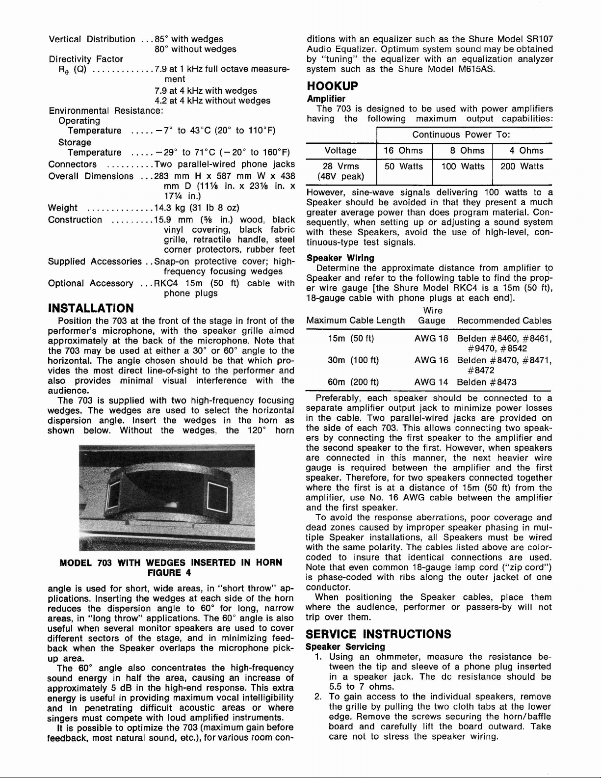
The 703 is supplied with two high-frequency focusing
wedges. The wedges are used to select the horizontal
dispersion angle. Insert the wedges in the horn as
shown below. Without the wedges, the 120" horn
703
MODEL
angle is used for short, wide areas, in "short throw" applications. Inserting the wedges at each side of the horn
reduces the dispersion angle to 60" for long, narrow
areas, in "long throw" applications. The
useful when several monitor speakers are used to cover
different sectors of the stage, and in minimizing feedback when the Speaker overlaps the microphone pickup area.
sound energy in half the area, causing an increase of
approximately 5 dB in the high-end response. This extra
energy is useful in providing maximum vocal intelligibility
and in penetrating difficult acoustic areas or where
singers must compete with loud amplified instruments.
feedback, most natural sound, etc.), for various room con-
60" angle also concentrates the high-frequency
The
It is possible to optimize the 703 (maximum gain before
WITH WEDGES INSERTED IN HORN
FIGURE
30" or 60" angle to the
4
60" angle is also
ditions with an equalizer such as the Shure Model
Audio Equalizer. Optimum system sound may be obtained
by "tuning" the equalizer with an equalization analyzer
system such as the Shure Model
M615AS.
HOOKUP
Amplifier
The 703 is designed to be used with power amplifiers
having the following maximum output capabilities:
28 Vrms
x
However, sine-wave signals delivering 100 watts to a
Speaker should be avoided in that they present a much
greater average power than does program material. Consequently, when setting up or adjusting a sound system
with these Speakers, avoid the use of high-level, continuous-type test signals.
Speaker Wiring
Determine the approximate distance from amplifier
Speaker and refer to the following table to find the proper wire gauge [the Shure Model RKC4 is a 15m (50 ft),
18-gauge cable with phone plugs at each end].
Maximum Cable Length Gauge Recommended Cables
15m (50 ft) AWG 18 Belden #8460, #8461,
30m (1 00 ft) AWG 16 Belden #8470, #8471,
60m (200 ft) AWG 14 Belden #8473
Preferably, each speaker should be connected to a
separate amplifier output jack to minimize power losses
in the cable. Two parallel-wired jacks are provided on
the side of each 703. This allows connecting two speakers by connecting the first speaker to the amplifier and
the second speaker to the first. However, when speakers
are connected in this manner, the next heavier wire
gauge is required between the amplifier and the first
speaker. Therefore, for two speakers connected together
where the first is at a distance of
amplifier, use No. 16 AWG cable between the amplifier
and the first speaker.
To avoid the response aberrations, poor coverage and
dead zones caused by improper speaker phasing in multiple Speaker installations, all Speakers must be wired
with the same polarity. The cables listed above are
coded to insure that identical connections are used.
Note that even common 18-gauge
is phase-coded with ribs along the outer jacket of one
conductor.
When positioning the Speaker cables, place them
where the audience, performer or passers-by will not
trip over them.
Wire
#9470, #8542
#8472
15m (50 ft) from the
lamp cord ("zip cord")
SERVICE INSTRUCTIONS
Speaker Servicing
1. Using an ohmmeter, measure the resistance between the tip and sleeve of a phone plug inserted
in a speaker jack. The dc resistance should be
5.5 to 7 ohms.
2. To gain access to the individual speakers, remove
the grille by pulling the two cloth tabs at the lower
edge. Remove the screws securing the
board and carefully lift the board outward. Take
care not to stress the speaker wiring.
horn/baffle
SR107
40
color-
Page 3

3.
Using an ohmmeter, measure the resistance of each
speaker voice coil. A clicking sound will be made
by a "good" speaker when an ohmmeter is connected or disconnected. Note that the resistance of
&inch speaker cannot be measured without
each
disconnecting a lead from one of its terminals. Each
8-inch speaker should measure between 11 and
13 ohms. The high-frequency driver should measure
7.7
between 6.7 and
ohms with its leads discon-
nected.
4. If the above tests do not locate the problem, apply
a small ac voltage from an oscillator and amplifier
to each speaker individually (approximately
4V,
50 Hz to 5 kHz for &inch speakers; approximately
2V,
3
kHz to 15 kHz for high-frequency driver).
ing plate to
mounting plate and driver from
4.
Replace driver diaphragm and voice coil assembly
as described in High-Frequency Diaphragm and Coil
instruction sheet.
5. For earlier production units, carefully place repaired
or new high-frequency driver in position over
baffle board, taking care to line up holes in driver
over holes in
terminals are positioned toward low-frequency
speakers. Replace three No. 6-32 x
and tighten high-frequency driver assembly.
6. For later production units, carefully place repaired
or new high-frequency driver in position over
baffle board with driver terminals toward low-
horn/baffle board. Remove driver
horn/baffle board.
horn/baffle board. Be sure that driver
1% in. screws,
frequency speakers and three screw heads of driver
seated in three cutouts in rear of horn. Position
WARNING
Sound pressure levels generated by this test may
be damaging to your hearing. Aim speakers away
from listeners and toward sound-absorbent material
(curtains, blanket, etc.). Carefully adjust test signal
amplitude to avoid unnecessarily high sound pressure levels for prolonged periods.
driver mounting plate over driver, lining up holes
in mounting plate over threaded bosses. Replace
two No. 10-16 x 1 in. screws, and tighten securely.
7. Replace driver leads. Note polarity marking or:
driver.
8. Reassemble
horn/baffle board to enclosure and
fasten securely to avoid rattles. Replace grille,
GUARANTEE
This Shure product is guaranteed in normal use to be
free from electrical and mechanical defects for a period
As the test signal frequency is varied, any erratic
buzzes or rattles indicate possible failure.
5. After servicing, replace the speakers and
horn/
baffle board, and tighten all hardware to avoid
rattles. Replace the grille.
High-Frequency Driver Replacement
To replace the high-frequency driver, follow these steps:
1. Remove grille and horn/baffle board as described
in Speaker Servicing.
2.
Remove leads from driver terminals. Note color Attention: Service Department
coding of speaker wires.
3.
For earlier oroduction units. remove three No. 6-32
x 1% in. sdrews securing high-frequency driver to
of one year from date of purchase. Please retain proof of
purchase date. This guarantee includes all parts and
labor. This guarantee is in lieu of any and all other guarantees or warranties, express or implied, and there shall
be no recovery for any consequential or incidental
damages.
SHIPPING INSTRUCTIONS
Carefully repack the unit and return
it
prepaid
Shure Brothers Incorporated
1501 West Shure Drive
Arlington Heights, Illinois 60004
If outside the United States, return the unit to your
horn/baffle board. For later production units, remove dealer or Authorized Shure Service Center for repair.
two No. 10-16 x 1 in. screws holding driver mount-
The unit will be returned to you prepaid.
horn/
horn/
NOTES
(.ALL
RESISTORS
OTHERWISE
TO
SPECIFIED.
BE
10%
,
UNLE55
CIRCUIT DIAGRAM
FIGURE
5
Page 4

REPLACEMENT PARTS LIST
Reference
Designation
A1
A2
C101
C102
C103
J1, J2
L101
L102
LSl, LS2
LS3
PI
M
M P2
M P3
M P4
MP5
M P6
M P7
M P8
M
P9
MP10
MP11
MP12
MP13
MP14
MP15
MP16
MP17
R101, R102
R103
Replacement
Kit
No."
-
RKC153*
RKC156*
*
*
-
A
-
-
-
-
-
-
-
A
-
-
-
-
-
-
-
-
-
-
-
-
-
-
-
-
-
-
-
Qty.
-
1
1
-
-
-
-
-
-
-
-
A
-
-
-
-
-
-
-
-
-
-
-
-
-
-
-
-
-
Part No.
90A2753
80231 6
80Y316
50G71
50E71
50F71
90BA2600
95A647
95A823
80A356
80A316
80B316*
80C316*
60A65
66A158
65A1338A
39A463
90A2756
53A1711
90BH2600
53A1656B
30A1002B
30L903C
30H903C
30A882B
30A1115A
95A889
90A2862
53A1775
30F1154A
45HC320E
45EC200G
*
*
*
Replacement Kit Consists
Crossover Network Assembly
High-Frequency Diaphragm and Coil
Capacitor, Mylar, 3.3
Capacitor, Mylar, 4.4 lo%, 250 WVdc*
Capacitor, Mylar, 9.4 ELF, lo%, 250 WVdc*
Connector, Phone Jack, 2-Conductor, Open
Circuit
Inductor, 0.5
Inductor, 0.3
8-inch Loudspeaker
High-Frequency Driver (see A2 for
replacement diaphragm and coil assembly)
703 Speaker Enclosure Assembly
Handle, Feet, Corner Protectors;
Speakers, Crossover Network, Horn/Baffle
Board, Grille Assembly)
Foot, Rubber
HornlBaffle Board
Nameplate
Grille Assembly (with Nameplate)
Connector Plate (without Connectors)
Retractile Handle Assembly
Corner Protector
Carriage Bolt, Aluminum, 2" (Crossover
Network)
Phillips Round Head Machine Screw,
#lo-32UNF-2A, 1
Phillips Round Head Machine
#
10-32, % (Feet)
Phillips Flat Head Wood Screw, #6,
1
%I"
(Horn/Baffle Board)
Threaded Nail, #6,
5h"
(Corner Protectors)
Front Cover
High-Frequency Focusing Wedge
Driver Mounting Plate
Phillips Pan Head Thread Forming Screw,
#lo-16, 1" (Driver)
Resistor, Wirewound, 32 ohms,
Resistor, Wirewound, 20 ohms,
mH, 0.45 ohms
mH, 0.33 ohms
Of:
Description
ELF, lo%, 250 WVdc*
VE
"
(Horn/Baffle Board)
(including
Screw,
15W, 10%
22W, 10%
*
*
* *
*
*
without
*
Parts listed as RKC Kits should be ordered by that kit number. Any orders received for piece parts where RKC Kit number
is shown will be shipped in RKC quantities.
**
Replacement diaphragm and coil assemblies
RKC156. Inspect driver for part number.
*"
Selected for low dissipation factor.
not
interchangeable: 80A316 driver uses RKC153; 80B316 and 80C316 use
 Loading...