

Page 1
-
222
HARTREY
AVE.,
EVANSTON,
IL.
60204
U.S.A.
MODEL
702
STAGE MONITOR
AREA CODE 3121866.2200 . CABLE: SHUREMICRO
TWX: 910-231-0048 TELEX: 72-4381
SPEAKER SYSTEM
I
OPERATION AND SERVICE MANUAL
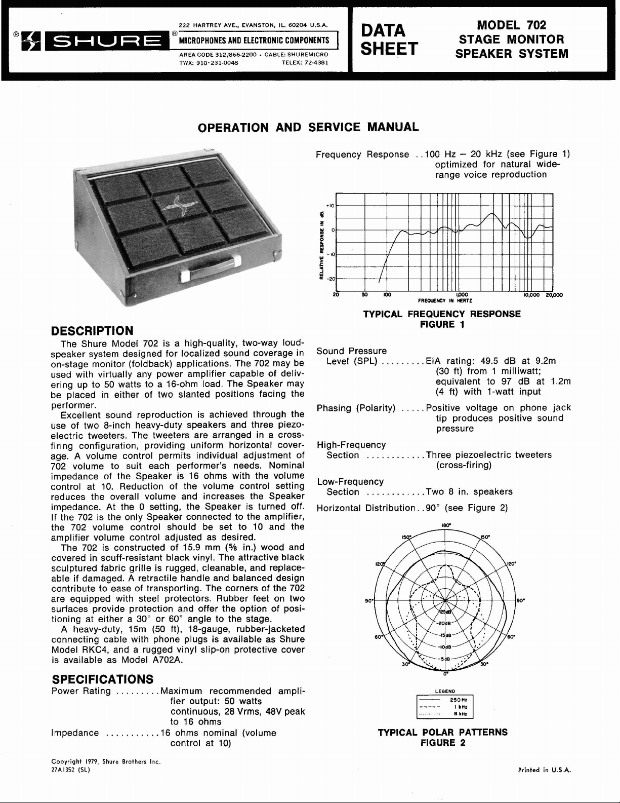
DESCRIPTION
The Shure Model 702 is a high-quality, two-way loudspeaker system designed for localized sound coverage in
on-stage monitor (foldback) applications. The 702 may be
used with virtually any power amplifier capable of delivering up to 50 watts to a 16-ohm load. The Speaker may
be placed in either of two slanted positions facing the
performer.
Excellent sound reproduction is achieved through the
use of two
electric tweeters. The tweeters are arranged in a
firing configuration, providing uniform horizontal coverage. A volume control permits individual adjustment of
702 volume to suit each performer's needs. Nominal
impedance of the Speaker is 16 ohms with the volume
control at 10. Reduction of the volume control setting
reduces the overall volume and increases the Speaker
impedance. At the
If the 702 is the only Speaker connected to the amplifier,
the 702 volume control should be set to
amplifier volume control adjusted as desired.
The 702 is constructed of 15.9 mm
covered in scuff-resistant black vinyl. The attractive black
sculptured fabric grille is rugged, cleanable, and replaceable if damaged. A retractile handle and balanced design
contribute to ease of transporting. The corners of the 702
are equipped with steel protectors. Rubber feet on two
surfaces provide protection and offer the option of positioning at either a
A heavy-duty,
connecting cable with phone plugs is available as Shure
Model
is available as Model
&inch heavy-duty speakers and three piezo-
cross-
0 setting, the Speaker is turned off.
10 and the
(%
in.) wood and
30" or 60" angle to the stage.
15m (50 ft), 18-gauge, rubber-jacketed
RKC4, and a rugged vinyl slip-on protective cover
A702A.
Frequency Response
TYPICAL FREQUENCY RESPONSE
Sound Pressure
Level (SPL) .EIA rating: 49.5 dB at 9.2m
Phasing (Polarity)
High-Frequency
Section .Three piezoelectric tweeters
Low-Frequency
Section .Two 8 in. speakers
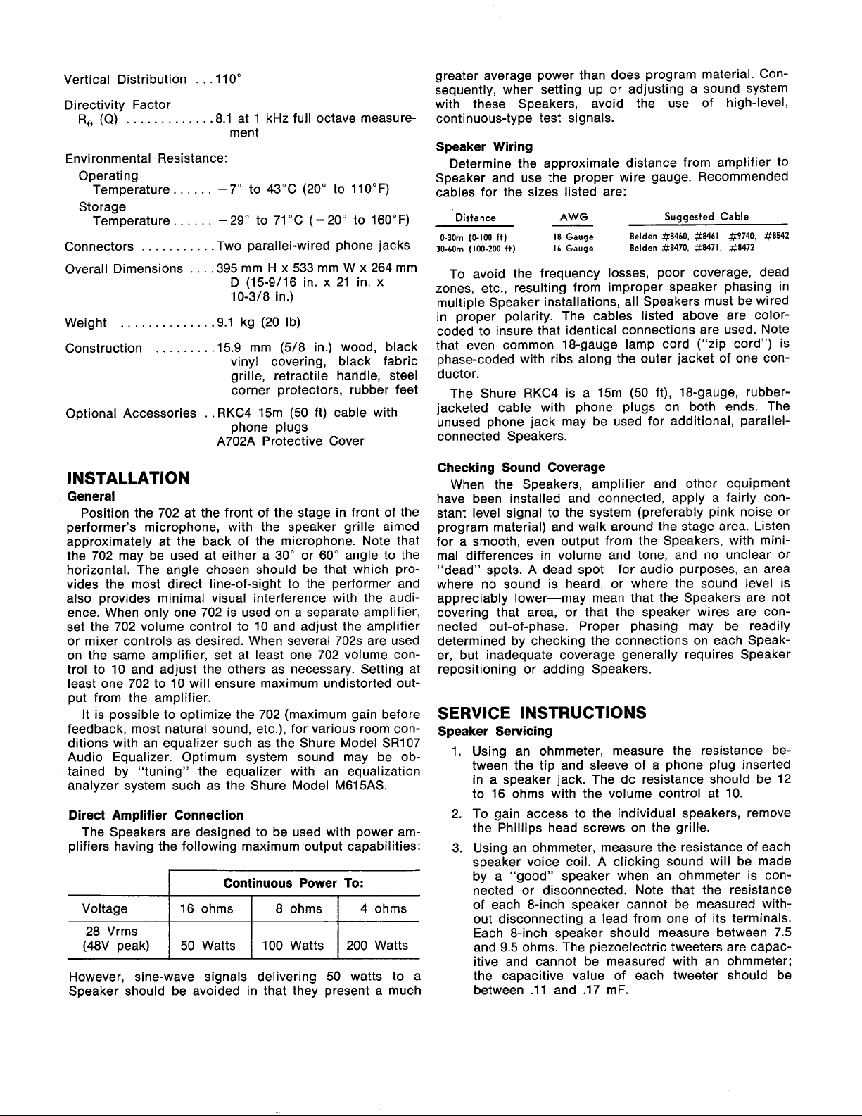
Horizontal Distribution.
........
...........
...........
.
,100 Hz - 20 kHz (see Figure 1)
optimized for natural
range voice reproduction
FIGURE
....
.Positive voltage on phone jack
.SO0 (see Figure 2)
1
(30 ft) from 1 milliwatt;
equivalent to 97 dB at 1.2m
(4 ft) with 1-watt input
tip produces positive sound
pressure
(cross-firing)
wide-
SPECIFICATIONS
Power Rating
Impedance
Copyright 1979. Shure Brothers Inc.
27A1352
(SL)
........
..........
.Maximum recommended ampli-
fier output: 50 watts
continuous, 28 Vrms, 48V peak
to 16 ohms
.16 ohms nominal (volume
control at 10)
LEGEND
...........
TYPICAL POLAR PATTERNS
FIGURE
8
kHz
2
Printed in
U.S.A.
Page 2
Vertical Distribution
Directivity Factor
R,
(Q)
. . . . . .
Environmental Resistance:
Operating
Temperature.
Storage
Temperature
.
.
. .
. .
. . . . . . . . .
Connectors
Overall Dimensions
Weight
Construction
Optional Accessories
. . . . .
. . . .
. . . . . .
. .
. .
.
. . . . . .
.
.
.llOO
.
.8.1 at 1 kHz full octave measure-
.
.Two parallel-wired phone jacks
.
.
.
.395 mm H x 533 mm W x 264 mm
.
. . .
.9.1 kg (20 Ib)
.
.15.9 mm (5/8 in.) wood, black
.
.
ment
-
7" to 43°C (20" to 110°F)
-
29" to 71 "C (-20" to 160°F)
(15-9/16 in. x 21 in. x
D
10-3/8 in.)
vinyl covering, black fabric
grille, retractile handle, steel
corner protectors, rubber feet
RKC4 15m (50 ft) cable with
phone plugs
A702A Protective Cover
greater average power than does program material. Consequently, when setting up or adjusting a sound system
with these Speakers, avoid the use of high-level,
continuous-type test signals.
Speaker Wiring
Determine the approximate distance from amplifier to
Speaker and use the proper wire gauge. Recommended
cables for the sizes listed are:
Distance
0-30m (0-100
30-60m (100-200
To avoid the frequency losses, poor coverage, dead
zones, etc., resulting from improper speaker phasing in
multiple Speaker installations, all Speakers must be wired
in proper polarity. The cables listed above are
coded to insure that identical connections are used. Note
that even common 18-gauge lamp cord ("zip cord") is
phase-coded with ribs along the outer jacket of one conductor.
The Shure RKC4 is a
jacketed cable with phone plugs on both ends. The
unused phone jack may be used for additional,
connected Speakers.
ft)
ft)
AWG
18 Gauge Belden #8460, #8461, #9740, Sf8542
I6 Gauge Belden #8470, #8471, #a472
15m (50 ft), 18-gauge, rubber-
Suggested Cable
color-
parallel-
INSTALLATION
General
Position the 702 at the front of the stage in front of the
performer's microphone, with the speaker grille aimed
approximately at the back of the microphone. Note that
the 702 may be used at either a 30" or
horizontal. The angle chosen should be that which provides the most direct line-of-sight to the performer and
also provides minimal visual interference with the audi-
ence. When only one 702 is used on a separate amplifier,
set the 702 volume control to 10 and adjust the amplifier
or mixer controls as desired. When several 702s are used
on the same amplifier, set at least one 702 volume control to 10 and adjust the others as necessary. Setting at
least one 702 to 10 will ensure maximum undistorted out-
put from the amplifier.
It is possible to optimize the 702 (maximum gain before
feedback, most natural sound, etc.), for various room conditions with an equalizer such as the Shure Model
Audio Equalizer. Optimum system sound may be obtained by "tuning" the equalizer with an equalization
analyzer system such as the Shure Model
Direct Amplifier Connection
The Speakers are designed to be used with power amplifiers having the following maximum output capabilities:
However, sine-wave signals delivering 50 watts to a
Speaker should be avoided in that they present a much
60" angle to the
SR107
M615AS.
Checking Sound Coverage
When the Speakers, amplifier and other equipment
have been installed and connected, apply a fairly constant level signal to the system (preferably pink noise or
program material) and walk around the stage area. Listen
for a smooth, even output from the Speakers, with mini-
mal differences in volume and tone, and no unclear or
"dead" spots. A dead spot-for audio purposes, an area
where no sound is heard, or where the sound level is
appreciably lower-may mean that the Speakers are not
covering that area, or that the speaker wires are connected out-of-phase. Proper phasing may be readily
determined by checking the connections on each Speaker, but inadequate coverage generally requires Speaker
repositioning or adding Speakers.
SERVICE
Speaker Servicing
1. Using an ohmmeter, measure the resistance between the tip and sleeve of a phone plug inserted
in a speaker jack. The dc resistance should be 12
to 16 ohms with the volume control at 10.
2. To gain access to the individual speakers, remove
the Phillips head screws on the grille.
3. Using an ohmmeter, measure the resistance of each
speaker voice coil. A clicking sound will be made
by a "good" speaker when an ohmmeter is con-
nected or disconnected. Note that the resistance
of each
out disconnecting a lead from one of its terminals.
Each 8-inch speaker should measure between 7.5
and 9.5 ohms. The piezoelectric tweeters are capacitive and cannot be measured with an ohmmeter;
the capacitive value of each tweeter should be
between
INSTRUCTIONS
&inch speaker cannot be measured with-
.ll
and .I7 mF.
Page 3

4. If the above tests do not locate the problem unit, 5. After servicing, replace the grille and tighten all
apply a small ac voltage from an oscillator and hardware to avoid rattles.
aipiifier to each speaker individually (approximate-
ly 4V, 50 Hz to 5 kHz for 8-inch speakers; approximately 2V, 3 kHz to 15 kHz for piezoelectric
tweeters). As the test signal frequency is varied, any
erratic buzzes or rattles indicate possible failure.
WARNING
Sound pressure levels generated by this test may
be damaging to your hearing. Aim speakers away
from listeners and toward sound-absorbent material (curtains, blanket, etc.). Carefully adjust
test signal amplitude to avoid unnecessarily high
sound pressure levels for prolonged periods.
J
I
v
r\
"
r,
-
-
BLACK
RED
CW
GUARANTEE
This Shure product is guaranteed in normal use to
be free from electrical and mechanical defects for a
period of one year from date of purchase. Please
retain proof of purchase date. This guarantee includes
all parts and labor. This guarantee is in lieu of any
and all other guarantees or warranties, express or
implied, and there shall be no recovery for any con-
sequential or incidental damages.
SHIPPING INSTRUCTIONS
Carefully repack the unit and return it prepaid to:
Shure Brothers Incorporated
Attention: Service Department
1501 West Shure Drive
Arlington Heights, Illinois 60004
If outside the United States, return the unit to your
dealer or Authorized Shure Service Center for repair.
The unit will be returned to you prepaid.
z
W
U
IT€
-
T T T
i-A.
Z
WATT
-
GRAY
-
PARALLEL
IN
JZ
PUTS
RED
VOLUME
v-
-
BLACK
REPLACEMENT PARTS LIST
Reference
Designation
J1-J2
LSI-LS2
LS3-LS5
MPI
M P2
M P3
M P4
M P5
M P6
M P7
M P8
M
P9
MP10
MP11
MP12
MP13
MP14
R
1
R2
Replacement
Kit No.
-
RKCI 54
RKCI 55
-
-
RKCI 50
-
-
-
-
-
-
-
-
-
-
-
-
-
Qty.
-
1
1
-
-
1
-
-
-
-
-
-
-
-
-
-
-
-
R
80-
1
RED
A
-
CIRCUIT DIAGRAM
FIGURE
Part No.
90BA2600
80A348
80A343
60A64
80A347
94A1312A
66A158
488064
48C064
53A1656B
31 A1 340
53A1626
39A464
39A463
30N893B
30H988B
30A1087A
90BG2600
45CC220D
I
-
3
Replacement Kit Consists Of:
Description
Connector, Phone Jack, 2-Conductor, Open Circuit
8-inch Loudspeaker
Piezoelectric Tweeter
Speaker Enclosure Assembly (including Handle, Corner
Protectors; without Speakers, Tweeters, Grille, Connector Plate Assembly, Caution Plate, Feet)
Grille
Retractile Handle Assembly
Foot
Chrome Trim Strip, Horizontal
Chrome Trim Strip, Vertical
Corner Protector
Volume Control Knob
Connector Plate (without connectors or volume control)
Caution Plate
Nameplate
Phillips Pan Head Machine Screw, #8-32,
Phillips Round Head Machine Screw, #8-32, (Feet)
Threaded Nail,
Rheostat, 80 ohms
Resistor, Wirewound, 22 ohms,
Ti"
(Corner Protectors)
-
BLACK
1353-1 1-2
lo%, 2W
1%'' (Grille)
Parts listed as RKC Kits should be ordered by that kit number. Any orders received for piece parts where RKC Kit number is
shown will be shipped in RKC quantities.
 Loading...