Shure P300 User Manual

P300

Command Strings

P300 command strings for third-party control systems, such as Crestron or Extron.

Version: 3.1 (2021-B)

Shure Incorporated

Table of Contents


Conventions

3

P300 Command Strings

3

Example Scenario: Muting a System

4


P300 Command Strings

3

Command Strings (Common)

6


2/41

Shure Incorporated

P300

Command Strings

P300 Command Strings

The device is connected via Ethernet to a control system, such as AMX, Crestron or Extron.

Connection: Ethernet (TCP/IP; select “Client” in the AMX/Crestron program)

Port: 2202

If using static IP addresses, the “ Shure Control” and the “Audio Network” settings must be set to manual in Designer. Use the

Control IP address for TCP/IP communication with Shure devices.

Conventions

The device has 4 types of strings:

GET

Finds the status of a parameter. After the AMX/Crestron sends a GET command, the P300 responds with a REPORT string

SET

Changes the status of a parameter. After the AMX/Crestron sends a SET command, the P300 will respond with a REPORT string to indicate the new value of the parameter.

REP

When the P300 receives a GET or SET command, it will reply with a REPORT command to indicate the status of the para­ meter. REPORT is also sent by the P300 when a parameter is changed on the P300.

SAMPLE

Used for metering audio levels.

All messages sent and received are ASCII. Note that the level indicators and gain indicators are also in ASCII

Most parameters will send a REPORT command when they change. Thus, it is not necessary to constantly query parameters. The P300 will send a REPORT command when any of these parameters change.

The character

“x”

in all of the following strings represents the channel of the P300 and can be ASCII numbers 0 through 4 as in the following ta­ ble

00

All Channels

01-08

Dante Inputs with Mic Processing

09-10

Dante Inputs

11-12

Analog Inputs

3/41

Shure Incorporated

13

USB Input

14

Mobile Input

15-16

Dante Outputs

17-18

Analog Outputs

19

USB Output

20

Mobile Output

21

Automixer Output

22

AEC Reference

23-28

Dante Outputs (firmware 4.1.x and newer)

Example Scenario: Muting a System

The Acoustic Echo Canceler (AEC) and P300 automixer require constant audio signal from the microphone to operate. Do NOT send commands to the microphone to mute locally. Instead, use logic communication between the P300 and Microflex

Advance devices. This allows the AEC to continue processing audio even while the system is muted, and deliver the best re­ sults when the system is unmuted.

After logic functionality is set up between Shure devices, send the command from the control system to mute the P300 au­ tomixer output. If set up correctly, the P300 automixer output will mute, and the microphone LED color will change to indicate the system is muted.

Note: Although the MXA310 LED status shows the system is muted, the audio signal is still passed to the P300 to allow contin­ uous processing.

Crestron/AMX Control System

Crestron/AMX sends the mute command to the P300.

P300

The LED command to indicate mute state is sent from the P300 to the MXA310.

MXA310

The MXA310 sends audio to the P300 for continuous processing.

Required Steps for Logic Functionality

1.In the MXA310 web application, go to Configuration >  ButtonControl, then set mode to Logic Out.

2.In Designer, open the P300 and go to the Input tab. Enable Logic for every channel routed from the MXA310 micro­ phone. The device type appears at the bottom of the input channel strip.

Note: The MXA910 does not require set up for logic functionality.

4/41

Shure Incorporated

Mute Command

Crestron/AMX sends the mute command to the P300.

LED Command

The P300 sends the LED command to the MXA310 so that the microphone LED color matches the system mute state.

Continuous Audio Signal

The MXA310 sends audio to the P300 for continuous processing. The system is muted from the P300 at the end of the au­ dio chain.

Best Practices for Muting:

Mute Button:

Press the mute button on the Crestron/AMX panel.

Crestron/AMX sends following command to P300:

<SET 21 AUTOMXR_MUTE TOGGLE >

Note: The TOGGLE command simplifies logic within the Crestron/AMX. ON/OFF commands can be used instead, but supple­ mental processes must be implemented within the Crestron/AMX.

P300 Automixer channels mute, and P300 sends following REPORT back to Crestron/AMX:

<REP 21 AUTOMXR_MUTE ON >

5/41

Shure Incorporated

This REPORT command can be used in various ways for button feedback on the control surface.

Command Strings (Common)

Get All

Command String:

< GET xx ALL >

P300 Response:

< REP ... >

Get Model Number

Command String:

< GET MODEL >

P300 Response:

< REP MODEL {yyyyyyyyyyyyyyyyyyyyyyyyyyyyyyyy} >

Get Serial Number

Command String:

< GET SERIAL_NUM >

P300 Response:

< REP SERIAL_NUM {yyyyyyyyyyyyyyyyyyyyyyyyyyyyyyyy} >

Get Channel Name

Command String:

< GET xx CHAN_NAME >

P300 Response:

< REP xx CHAN_NAME {yyyyyyyyyyyyyyyyyyyyyyyyyyyyyyy} >

Where xx is ASCII channel number: 00 through 21, 23-28. Use this command on first power on to update the status of all parameters.

The P300 responds with individual Re­ port strings for all parameters.

Where yyyyyyyyyyyyyyyyyyyyyyyyyyyyyyyy is 32 characters of the model number. The P300 always responds with a 32 character model number.

Where yyyyyyyyyyyyyyyyyyyyyyyyyyyyyyyy is 32 characters of the serial number. The

P300 always responds with a 32 char­ acter serial number.

Where xx is ASCII channel number: 00 through 20, 23-28.

Where yyyyyyyyyyyyyyyyyyyyyyyyyyyyyyy is 31 characters of the user name. The

P300 always responds with a 31 char­ acter name.

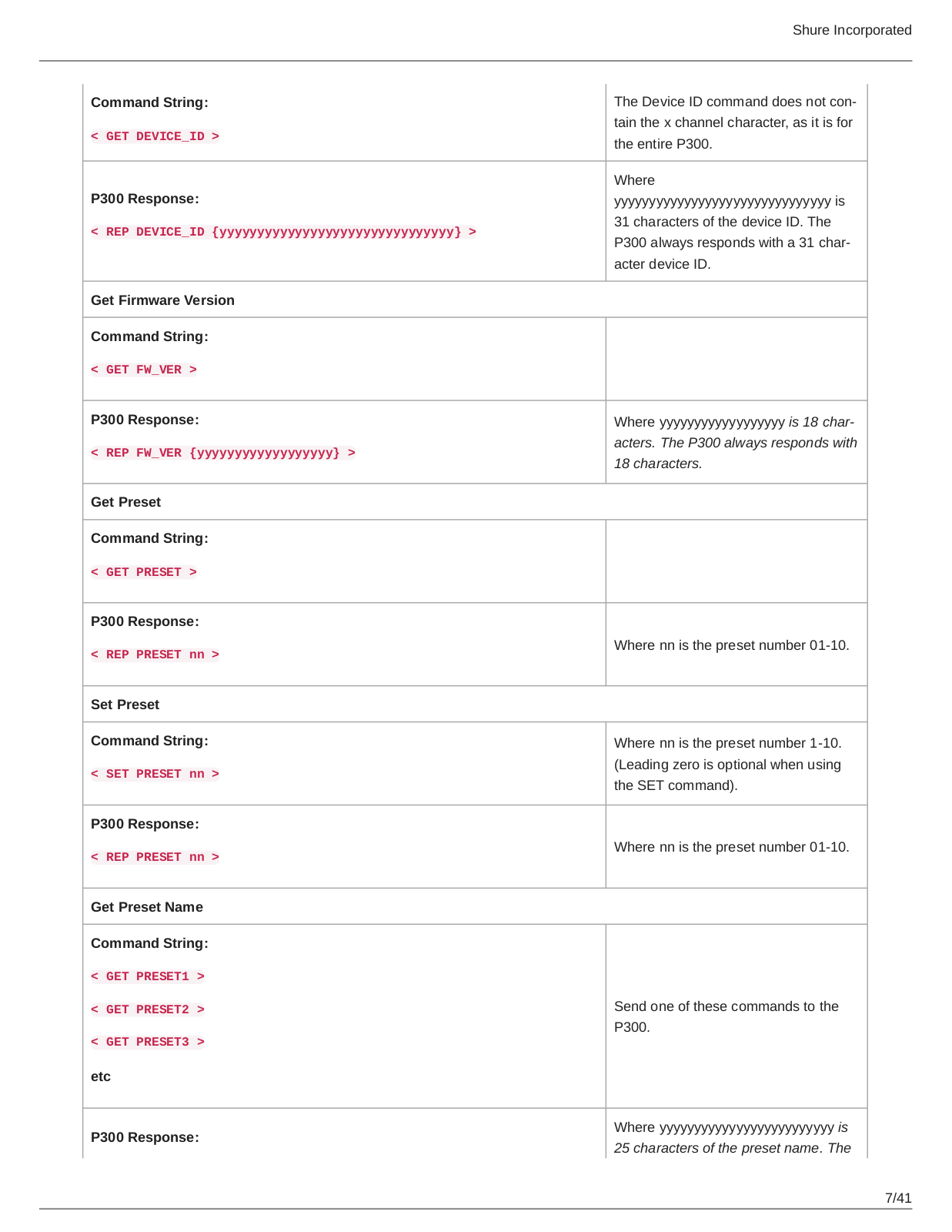
Get Device ID

6/41

Command String:

< GET DEVICE_ID >

P300 Response:

< REP DEVICE_ID {yyyyyyyyyyyyyyyyyyyyyyyyyyyyyyy} >

Get Firmware Version

Command String:

< GET FW_VER >

P300 Response:

< REP FW_VER {yyyyyyyyyyyyyyyyyy} >

Get Preset

Command String:

< GET PRESET >

P300 Response:

< REP PRESET nn >

Set Preset

Command String:

< SET PRESET nn >

P300 Response:

< REP PRESET nn >

Get Preset Name

Command String:

<GET PRESET1 >

<GET PRESET2 >

<GET PRESET3 >

etc

P300 Response:

Shure Incorporated

The Device ID command does not con­ tain the x channel character, as it is for the entire P300.

Where yyyyyyyyyyyyyyyyyyyyyyyyyyyyyyy is 31 characters of the device ID. The

P300 always responds with a 31 char­ acter device ID.

Where yyyyyyyyyyyyyyyyyy is 18 char­ acters. The P300 always responds with 18 characters.

Where nn is the preset number 01-10.

Where nn is the preset number 1-10. (Leading zero is optional when using the SET command).

Where nn is the preset number 01-10.

Send one of these commands to the P300.

Where yyyyyyyyyyyyyyyyyyyyyyyyy is 25 characters of the preset name. The

7/41

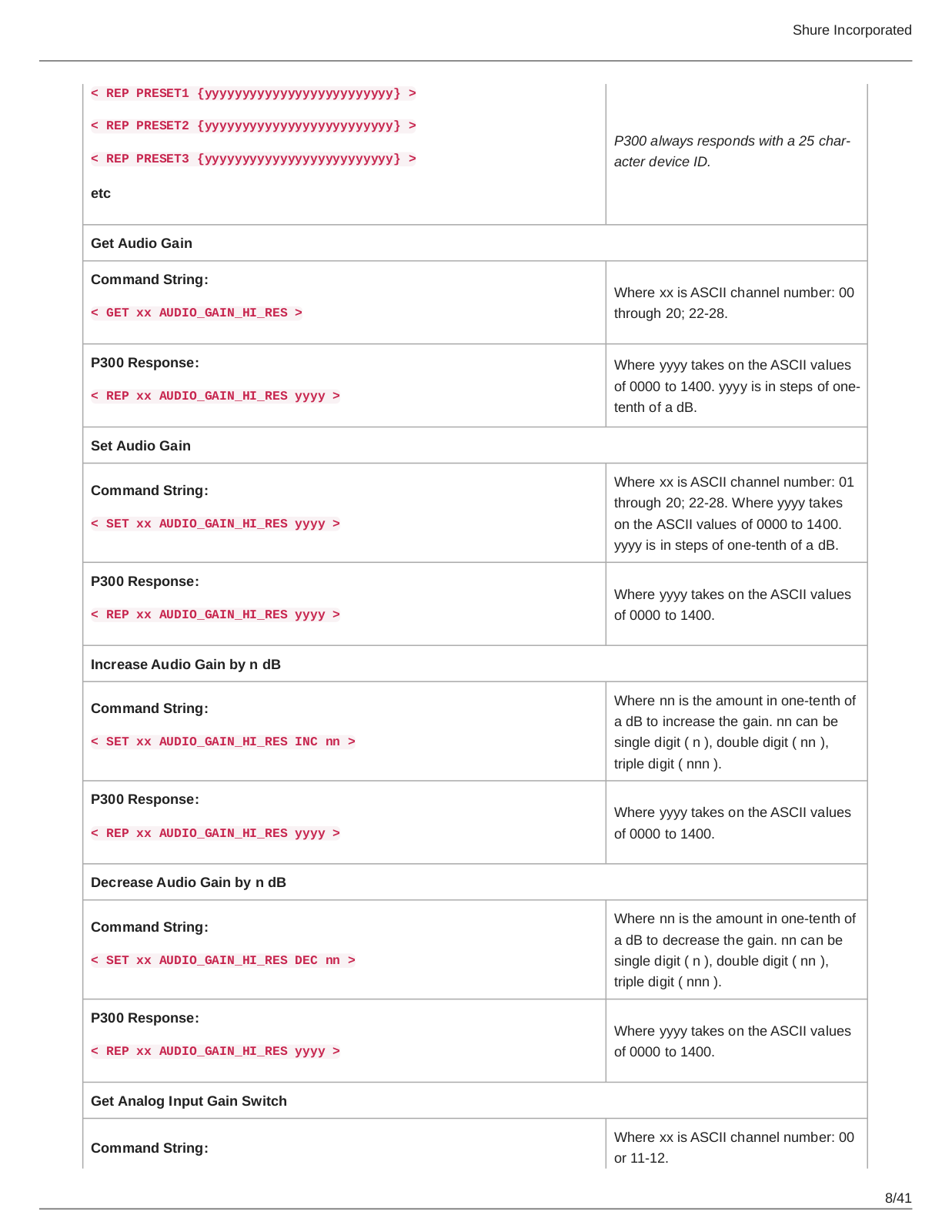
<REP PRESET1 {yyyyyyyyyyyyyyyyyyyyyyyyy} >

<REP PRESET2 {yyyyyyyyyyyyyyyyyyyyyyyyy} >

<REP PRESET3 {yyyyyyyyyyyyyyyyyyyyyyyyy} >

etc

Get Audio Gain

Command String:

< GET xx AUDIO_GAIN_HI_RES >

P300 Response:

< REP xx AUDIO_GAIN_HI_RES yyyy >

Set Audio Gain

Command String:

< SET xx AUDIO_GAIN_HI_RES yyyy >

P300 Response:

< REP xx AUDIO_GAIN_HI_RES yyyy >

Increase Audio Gain by n dB

Command String:

< SET xx AUDIO_GAIN_HI_RES INC nn >

P300 Response:

< REP xx AUDIO_GAIN_HI_RES yyyy >

Decrease Audio Gain by n dB

Command String:

< SET xx AUDIO_GAIN_HI_RES DEC nn >

P300 Response:

< REP xx AUDIO_GAIN_HI_RES yyyy >

Get Analog Input Gain Switch

Command String:

Shure Incorporated

P300 always responds with a 25 char­ acter device ID.

Where xx is ASCII channel number: 00 through 20; 22-28.

Where yyyy takes on the ASCII values of 0000 to 1400. yyyy is in steps of onetenth of a dB.

Where xx is ASCII channel number: 01 through 20; 22-28. Where yyyy takes on the ASCII values of 0000 to 1400. yyyy is in steps of one-tenth of a dB.

Where yyyy takes on the ASCII values of 0000 to 1400.

Where nn is the amount in one-tenth of a dB to increase the gain. nn can be single digit ( n ), double digit ( nn ), triple digit ( nnn ).

Where yyyy takes on the ASCII values of 0000 to 1400.

Where nn is the amount in one-tenth of a dB to decrease the gain. nn can be single digit ( n ), double digit ( nn ), triple digit ( nnn ).

Where yyyy takes on the ASCII values of 0000 to 1400.

Where xx is ASCII channel number: 00 or 11-12.

8/41

Shure P300 User Manual

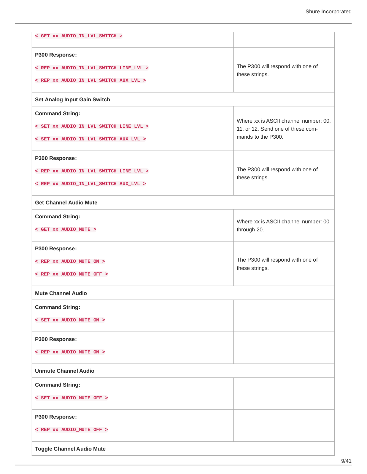
< GET xx AUDIO_IN_LVL_SWITCH >

P300 Response:

<REP xx AUDIO_IN_LVL_SWITCH LINE_LVL >

<REP xx AUDIO_IN_LVL_SWITCH AUX_LVL >

Set Analog Input Gain Switch

Command String:

<SET xx AUDIO_IN_LVL_SWITCH LINE_LVL >

<SET xx AUDIO_IN_LVL_SWITCH AUX_LVL >

P300 Response:

<REP xx AUDIO_IN_LVL_SWITCH LINE_LVL >

<REP xx AUDIO_IN_LVL_SWITCH AUX_LVL >

Get Channel Audio Mute

Command String:

< GET xx AUDIO_MUTE >

P300 Response:

<REP xx AUDIO_MUTE ON >

<REP xx AUDIO_MUTE OFF >

Mute Channel Audio

Command String:

< SET xx AUDIO_MUTE ON >

P300 Response:

< REP xx AUDIO_MUTE ON >

Unmute Channel Audio

Command String:

< SET xx AUDIO_MUTE OFF >

P300 Response:

< REP xx AUDIO_MUTE OFF >

Toggle Channel Audio Mute

Shure Incorporated

The P300 will respond with one of these strings.

Where xx is ASCII channel number: 00,

11, or 12. Send one of these com­ mands to the P300.

The P300 will respond with one of these strings.

Where xx is ASCII channel number: 00 through 20.

The P300 will respond with one of these strings.

9/41

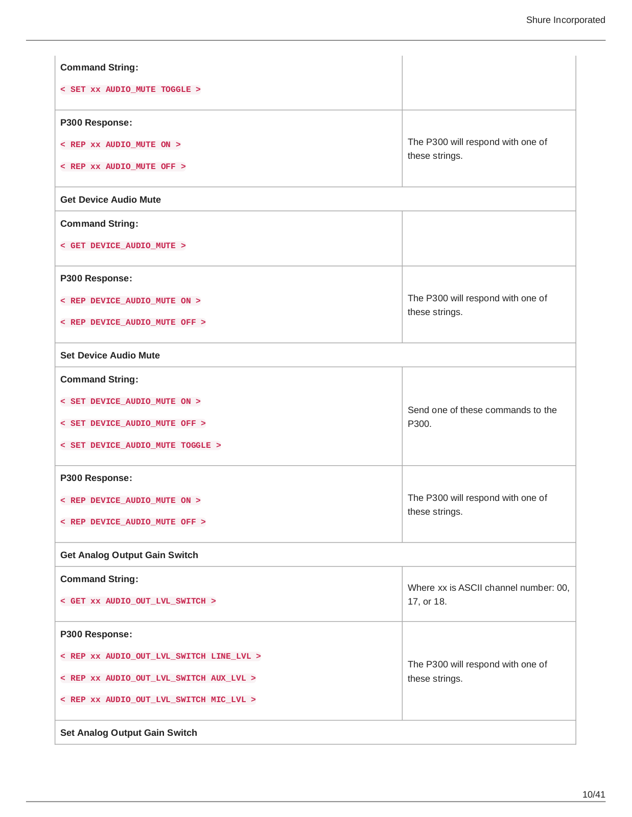
Command String:

< SET xx AUDIO_MUTE TOGGLE >

P300 Response:

<REP xx AUDIO_MUTE ON >

<REP xx AUDIO_MUTE OFF >

Get Device Audio Mute

Command String:

< GET DEVICE_AUDIO_MUTE >

P300 Response:

<REP DEVICE_AUDIO_MUTE ON >

<REP DEVICE_AUDIO_MUTE OFF >

Set Device Audio Mute

Command String:

<SET DEVICE_AUDIO_MUTE ON >

<SET DEVICE_AUDIO_MUTE OFF >

<SET DEVICE_AUDIO_MUTE TOGGLE >

P300 Response:

<REP DEVICE_AUDIO_MUTE ON >

<REP DEVICE_AUDIO_MUTE OFF >

Get Analog Output Gain Switch

Command String:

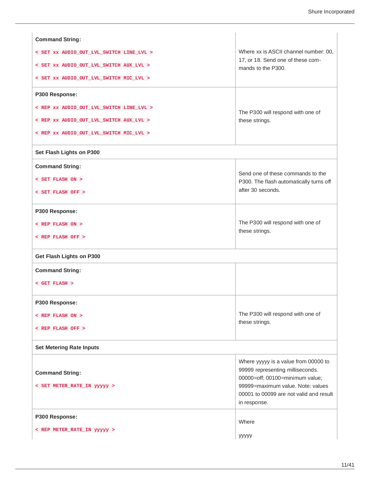
< GET xx AUDIO_OUT_LVL_SWITCH >

P300 Response:

<REP xx AUDIO_OUT_LVL_SWITCH LINE_LVL >

<REP xx AUDIO_OUT_LVL_SWITCH AUX_LVL >

<REP xx AUDIO_OUT_LVL_SWITCH MIC_LVL >

Set Analog Output Gain Switch

Shure Incorporated

The P300 will respond with one of these strings.

The P300 will respond with one of these strings.

Send one of these commands to the P300.

The P300 will respond with one of these strings.

Where xx is ASCII channel number: 00, 17, or 18.

The P300 will respond with one of these strings.

10/41

Command String:

<SET xx AUDIO_OUT_LVL_SWITCH LINE_LVL >

<SET xx AUDIO_OUT_LVL_SWITCH AUX_LVL >

<SET xx AUDIO_OUT_LVL_SWITCH MIC_LVL >

P300 Response:

<REP xx AUDIO_OUT_LVL_SWITCH LINE_LVL >

<REP xx AUDIO_OUT_LVL_SWITCH AUX_LVL >

<REP xx AUDIO_OUT_LVL_SWITCH MIC_LVL >

Set Flash Lights on P300

Command String:

<SET FLASH ON >

<SET FLASH OFF >

P300 Response:

<REP FLASH ON >

<REP FLASH OFF >

Get Flash Lights on P300

Command String:

< GET FLASH >

P300 Response:

<REP FLASH ON >

<REP FLASH OFF >

Set Metering Rate Inputs

Command String:

< SET METER_RATE_IN yyyyy >

P300 Response:

< REP METER_RATE_IN yyyyy >

Shure Incorporated

Where xx is ASCII channel number: 00,

17, or 18. Send one of these com­ mands to the P300.

The P300 will respond with one of these strings.

Send one of these commands to the P300. The flash automatically turns off after 30 seconds.

The P300 will respond with one of these strings.

The P300 will respond with one of these strings.

Where yyyyy is a value from 00000 to 99999 representing milliseconds. 00000=off; 00100=minimum value; 99999=maximum value. Note: values 00001 to 00099 are not valid and result in response.

Where

yyyyy

11/41

Shure Incorporated

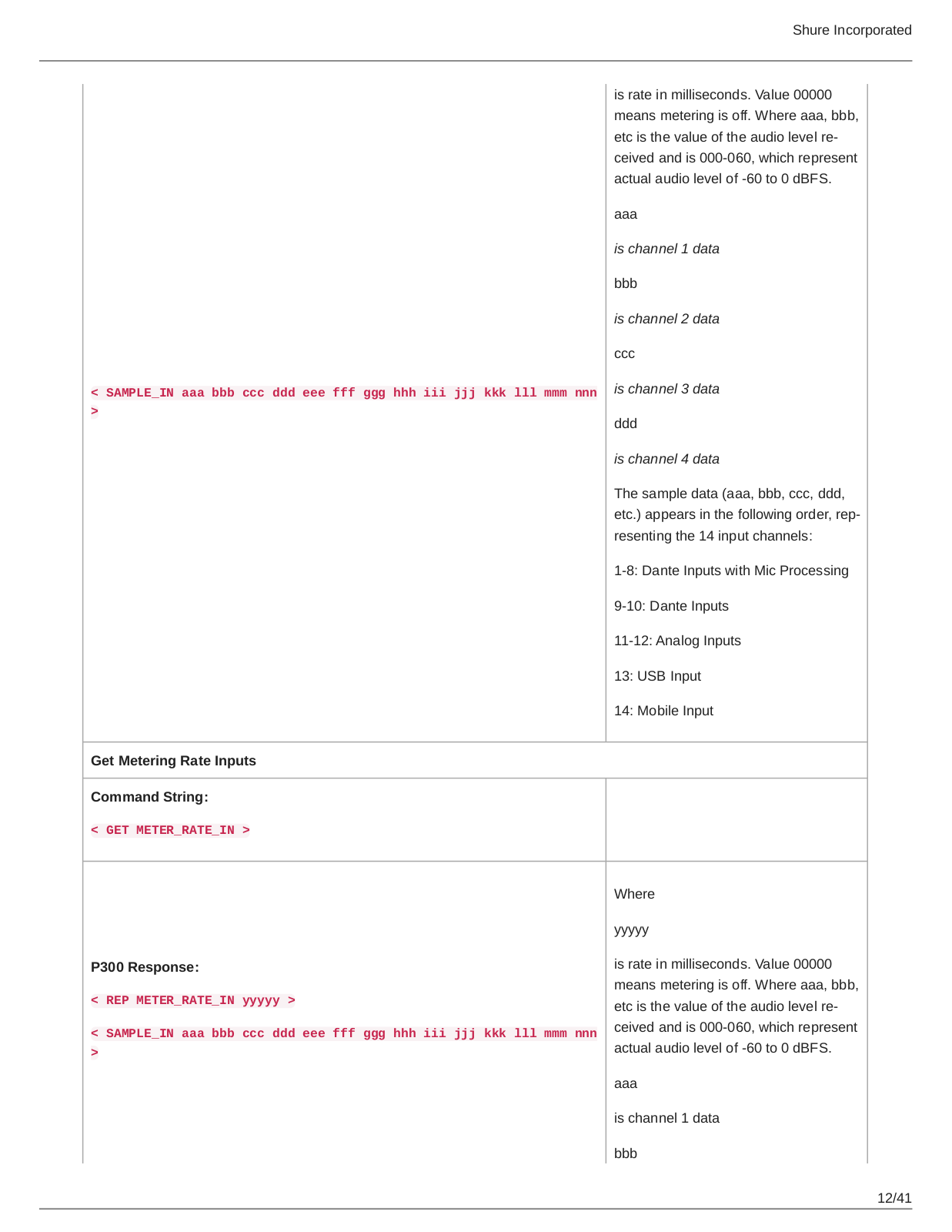
< SAMPLE_IN aaa bbb ccc ddd eee fff ggg hhh iii jjj kkk lll mmm nnn

>

Get Metering Rate Inputs

Command String:

< GET METER_RATE_IN >

P300 Response:

<REP METER_RATE_IN yyyyy >

<SAMPLE_IN aaa bbb ccc ddd eee fff ggg hhh iii jjj kkk lll mmm nnn

>

is rate in milliseconds. Value 00000 means metering is off. Where aaa, bbb, etc is the value of the audio level re­ ceived and is 000-060, which represent actual audio level of -60 to 0 dBFS.

aaa

is channel 1 data

bbb

is channel 2 data

ccc

is channel 3 data

ddd

is channel 4 data

The sample data (aaa, bbb, ccc, ddd, etc.) appears in the following order, rep­ resenting the 14 input channels:

1-8: Dante Inputs with Mic Processing

9-10: Dante Inputs

11-12: Analog Inputs

13:USB Input

14:Mobile Input

Where

yyyyy

is rate in milliseconds. Value 00000 means metering is off. Where aaa, bbb, etc is the value of the audio level re­ ceived and is 000-060, which represent actual audio level of -60 to 0 dBFS.

aaa

is channel 1 data

bbb

12/41

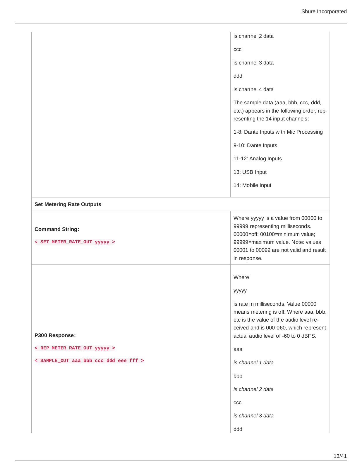
Set Metering Rate Outputs

Command String:

< SET METER_RATE_OUT yyyyy >

P300 Response:

<REP METER_RATE_OUT yyyyy >

<SAMPLE_OUT aaa bbb ccc ddd eee fff >

Shure Incorporated

is channel 2 data

ccc

is channel 3 data

ddd

is channel 4 data

The sample data (aaa, bbb, ccc, ddd, etc.) appears in the following order, rep­ resenting the 14 input channels:

1-8: Dante Inputs with Mic Processing

9-10: Dante Inputs

11-12: Analog Inputs

13:USB Input

14:Mobile Input

Where yyyyy is a value from 00000 to 99999 representing milliseconds. 00000=off; 00100=minimum value; 99999=maximum value. Note: values 00001 to 00099 are not valid and result in response.

Where

yyyyy

is rate in milliseconds. Value 00000 means metering is off. Where aaa, bbb, etc is the value of the audio level re­ ceived and is 000-060, which represent actual audio level of -60 to 0 dBFS.

aaa

is channel 1 data

bbb

is channel 2 data

ccc

is channel 3 data

ddd

13/41

Loading...
+ 28 hidden pages