

Shure MXWAPT8, MXWAPT4, MXWAPT2 User Manual
MXW
®
Microflex Wireless
The Shure microflex wireless system, MXW, user guide.
Version: 4 (2019-G)

Table of Contents
MXWMicroflex® Wireless 4
IMPORTANT SAFETY INSTRUCTIONS 4
Overview 4
General Description 5
Features 5
MXW Wireless System 7
Hardware Description 10
Audio Network Interface (ANI) 11
Access Point Transceiver (APT) 14
Networked Charger (NCS) 16
Microphone Transmitters 18
Rechargeable Batteries 24
Installation 29
Additional Equipment 29
Connecting MXW Components 30
Rack Installation 32
Securing the Charging Station 32
Two-Channel Charger Wall Mount 33
Mount the Access Point Transceiver 38
Power the Hardware 40
Open the MXW Control Software 41
System Set Up 42
Group Devices to Form Audio Channels 42
Channel Routing between Devices 46
Link Microphones to Group Channels 48
Preparing a Backup Microphone 50
Exchanging or Removing a Component 52
Link a Microphone Over the Network 52
Large Installations 53
Shure Incorporated
Shure SystemOn Software For Managing Large Systems 5
3
High Density Mode 53
Configurations: Managing Multiple Groups 53
Wireless Management 55
Overview of Channel Coordination 55
Scanning Available RF Spectrum 56
PHS Detection 57
Identifying PHS Detection Errors 58
Setting RF Power 59
Using Multiple 2- or 4-Channel Access Points 60
Networking 62
Networking Best Practices 62
Configuring IP Settings 63
Advanced Setup 65
Software 68
Shure Web Device Discovery Application 69
MXW System Control Software 70
Control Software for the MXW Audio Network Interface 82
Dante Software by Audinate 84
Firmware Updates 85
Troubleshooting 85
Additional Resources 87
Factory Reset 87
Accessories and Model Variations 88
Microflex Wireless Specifications 92
System 92
Transmitters 93
Access Point Transceiver (APT) 95
Networked Charging Station (NCS) 96
2/103

Shure Incorporated
Audio Network Interface (ANI) 97
Transmitter Output Power 99
Wiring Diagram 100
Safety Information 100
SAFETY PRECAUTIONS 101
WARNING 101
WARNING 101
Important Product Information 101
Information to the user 102
Certifications 102
Trademarks 103
3/103
MXW
Microflex Wireless
®
IMPORTANT SAFETY INSTRUCTIONS
1.
READ these instructions.
2.
KEEP these instructions.
3.
HEED all warnings.
4.
FOLLOW all instructions.
5.
DO NOT use this apparatus near water.
6.
CLEAN ONLY with dry cloth.
7.
DO NOT block any ventilation openings. Allow sufficient distances for adequate ventilation and install in accordance
with the manufacturer’s instructions.
8.
DO NOT install near any heat sources such as open flames, radiators, heat registers, stoves, or other apparatus (in
cluding amplifiers) that produce heat. Do not place any open flame sources on the product.
9.
DO NOT defeat the safety purpose of the polarized or grounding type plug. A polarized plug has two blades with one
wider than the other. A grounding type plug has two blades and a third grounding prong. The wider blade or the third
prong are provided for your safety. If the provided plug does not fit into your outlet, consult an electrician for replace
ment of the obsolete outlet.
10.
PROTECT the power cord from being walked on or pinched, particularly at plugs, convenience receptacles, and the
point where they exit from the apparatus.
11.
ONLY USE attachments/accessories specified by the manufacturer.
12.
USE only with a cart, stand, tripod, bracket, or table specified by the manufacturer, or sold with the apparatus. When a
cart is used, use caution when moving the cart/apparatus combination to avoid injury from tip-over.
Shure Incorporated
13.
UNPLUG this apparatus during lightning storms or when unused for long periods of time.
14.
REFER all servicing to qualified service personnel. Servicing is required when the apparatus has been damaged in any
way, such as power supply cord or plug is damaged, liquid has been spilled or objects have fallen into the apparatus,
the apparatus has been exposed to rain or moisture, does not operate normally, or has been dropped.
15.
DO NOT expose the apparatus to dripping and splashing. DO NOT put objects filled with liquids, such as vases, on the
apparatus.
16.
The MAINS plug or an appliance coupler shall remain readily operable.
17.
The airborne noise of the Apparatus does not exceed 70dB (A).
18.
Apparatus with CLASS I construction shall be connected to a MAINS socket outlet with a protective earthing connec
tion.
19.
To reduce the risk of fire or electric shock, do not expose this apparatus to rain or moisture.
20.
Do not attempt to modify this product. Doing so could result in personal injury and/or product failure.
21.
Operate this product within its specified operating temperature range.
4/103
Shure Incorporated
Overview
General Description
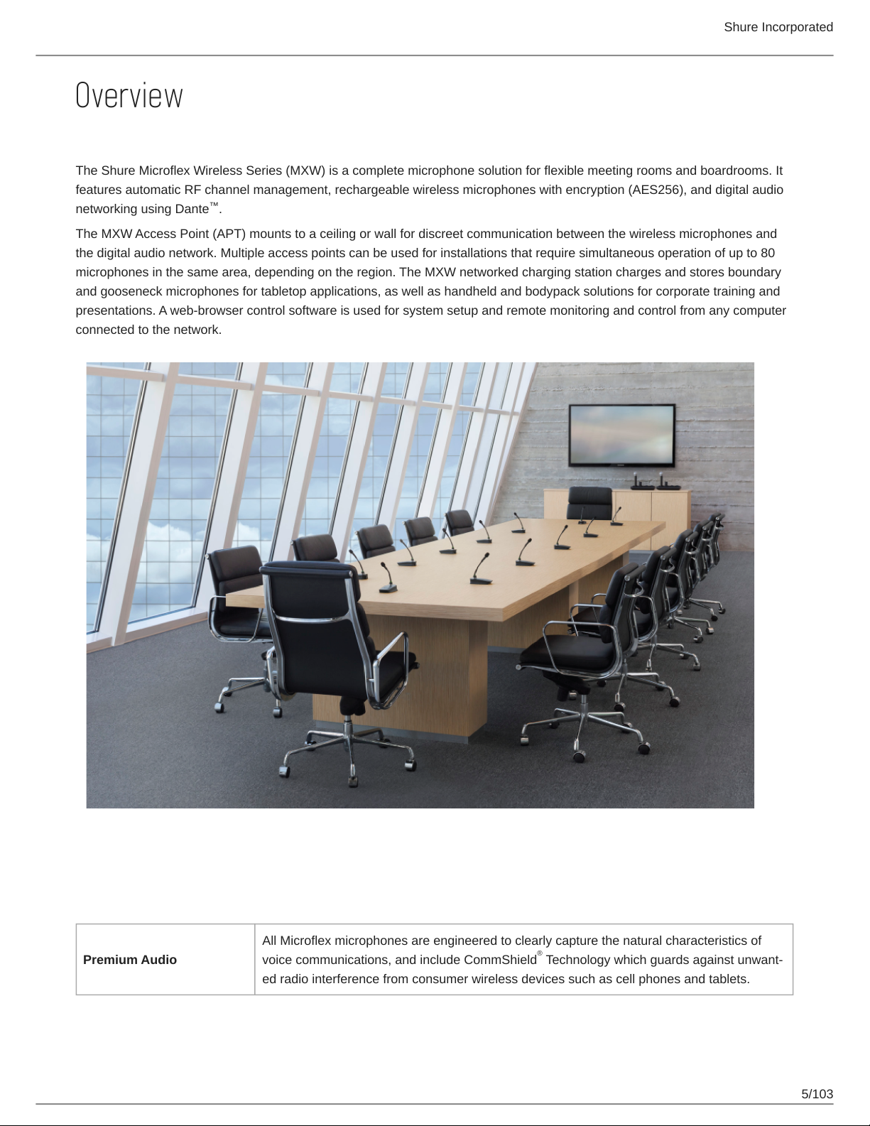
The Shure Microflex Wireless Series (MXW) is a complete microphone solution for flexible meeting rooms and boardrooms. It
features automatic RF channel management, rechargeable wireless microphones with encryption (AES256), and digital audio
networking using Dante .
The MXW Access Point (APT) mounts to a ceiling or wall for discreet communication between the wireless microphones and
the digital audio network. Multiple access points can be used for installations that require simultaneous operation of up to 80
microphones in the same area, depending on the region. The MXW networked charging station charges and stores boundary
and gooseneck microphones for tabletop applications, as well as handheld and bodypack solutions for corporate training and
presentations. A web-browser control software is used for system setup and remote monitoring and control from any computer
connected to the network.
™
Features
Legendary Shure Quality
All Microflex microphones are engineered to clearly capture the natural characteristics of
Premium Audio
voice communications, and include CommShield Technology which guards against unwant
ed radio interference from consumer wireless devices such as cell phones and tablets.
®
5/103
Rechargeable Micro
phones
Shure Incorporated
Each MXW microphone is powered from a rechargeable Lithium-ion battery, which can be
charged at any time without removal from the microphone. Battery statistics are viewable
from the control software (battery runtime, time to full charge, charge cycle count and battery
capacity).
Discreet, Professional De
sign
Modern, lowprofile wireless microphone designs elegantly integrate into diverse AV environ
ments. By eliminating wires, MXW noticeably reduces clutter and provides professional ele
gance.
The MXW wireless link is encrypted using the Advanced Encryption Standard (AES-256), as
Encryption
specified by the US Government National Institute of Standards and Technology (NIST) pub
lication FIPS-197.
Advanced Networking and Control
Digital audio is carried over standard Ethernet using shielded Cat5e (or higher) cables. De
veloped with Dante technology by Audinate , MXW provides low latency, clock synchro
Digital Audio Networking
Automatic Frequency Co
ordination
nization, and high Quality-of-Service (QoS) to provide reliable audio transport. Digital audio
can coexist safely on the same network as IT and control data, or can be configured to use a
dedicated network.
The MXW Series uses automatic frequency coordination to quickly set up all of the micro
phones and achieve reliable, uninterrupted wireless communication. Microphones are as
signed to channels on an access point transceiver simply by arranging them in an associat
ed charging station and pressing the Link button. Multiple access point transceivers can
work together to support large installations or scalable rooms. Once Linked, the system au
tomatically scans the available RF spectrum and selects the best quality RF channels on
which to operate. Upon detecting interference, microphones automatically switch to the best
alternate RF channel determined during continuous background scanning.
tm
®
Remote Control and Moni
toring
BuiltIn RF Spectrum Scan
ner
Microflex Wireless components and software are compatible with Crestron, AMX, and other
programmable controllers. Components interconnect with teleconferencing equipment and
digital signal processors.
The MXW Wireless components transmit in unlicensed spectrum that may be used by other
wireless devices (in particular wireless phones and headsets) operating in the same area.
The MXW access point features an RF scanner to document the average and peak RF inter
ference. The data provides an accurate estimate for the number of MXW channels that can
be safely operated in the scanned area.
6/103
MXW Wireless System
Shure Incorporated
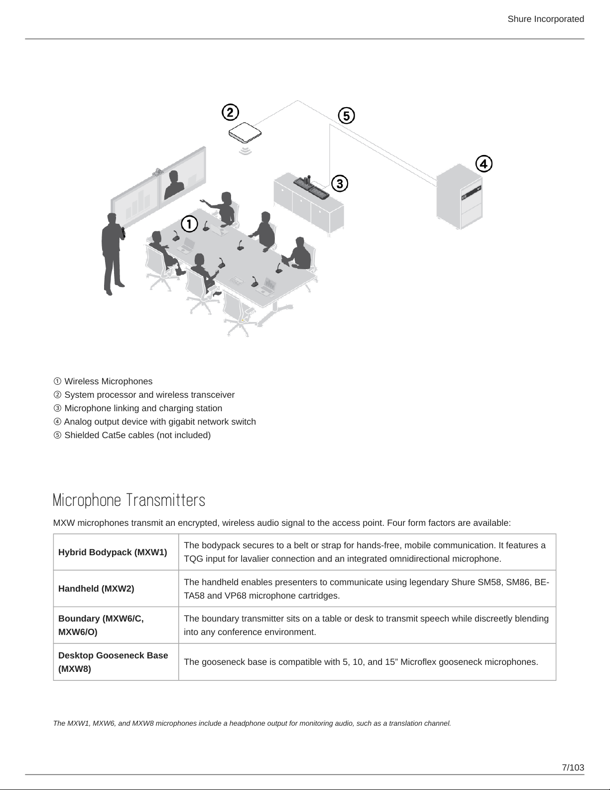
① Wireless Microphones
② System processor and wireless transceiver
③ Microphone linking and charging station
④ Analog output device with gigabit network switch
⑤ Shielded Cat5e cables (not included)
Components of the MXW System
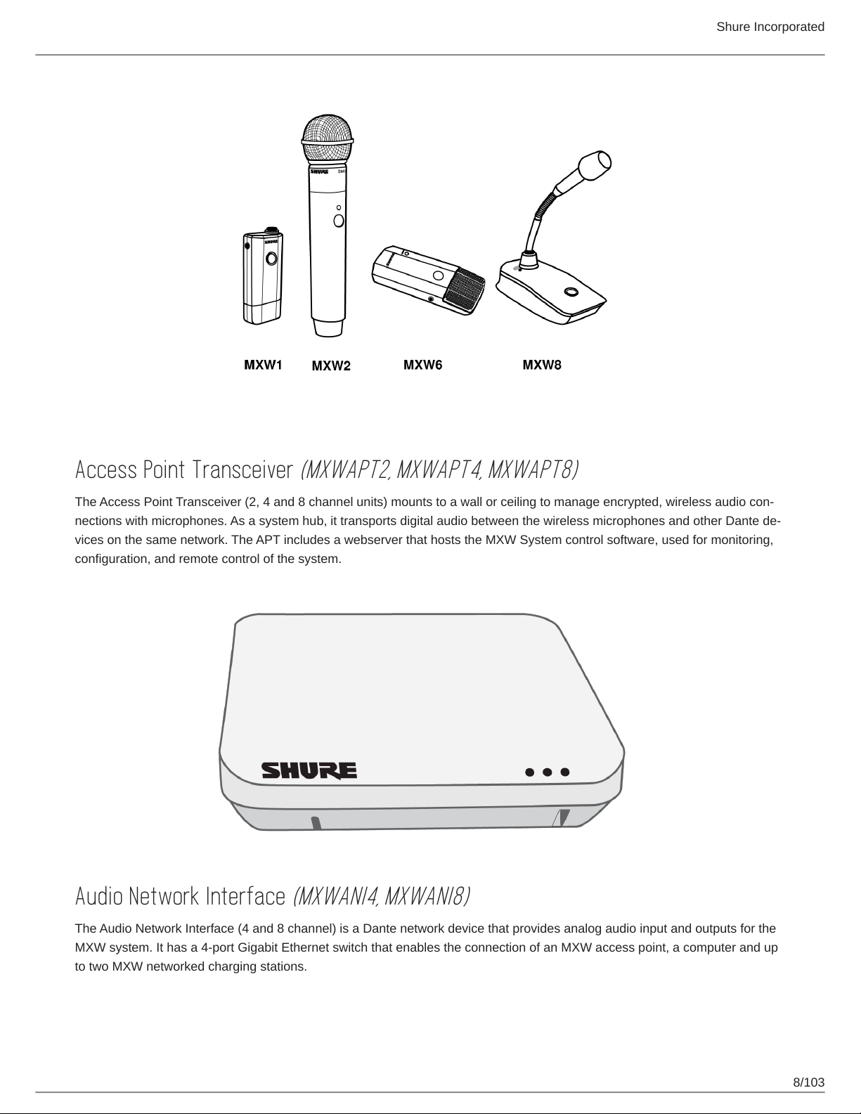
Microphone Transmitters
MXW microphones transmit an encrypted, wireless audio signal to the access point. Four form factors are available:
Hybrid Bodypack (MXW1)
Handheld (MXW2)
Boundary (MXW6/C,
MXW6/O)
Desktop Gooseneck Base
(MXW8)
The bodypack secures to a belt or strap for hands-free, mobile communication. It features a
TQG input for lavalier connection and an integrated omnidirectional microphone.
The handheld enables presenters to communicate using legendary Shure SM58, SM86, BE
TA58 and VP68 microphone cartridges.
The boundary transmitter sits on a table or desk to transmit speech while discreetly blending
into any conference environment.
The gooseneck base is compatible with 5, 10, and 15” Microflex gooseneck microphones.
The MXW1, MXW6, and MXW8 microphones include a headphone output for monitoring audio, such as a translation channel.
7/103
Shure Incorporated
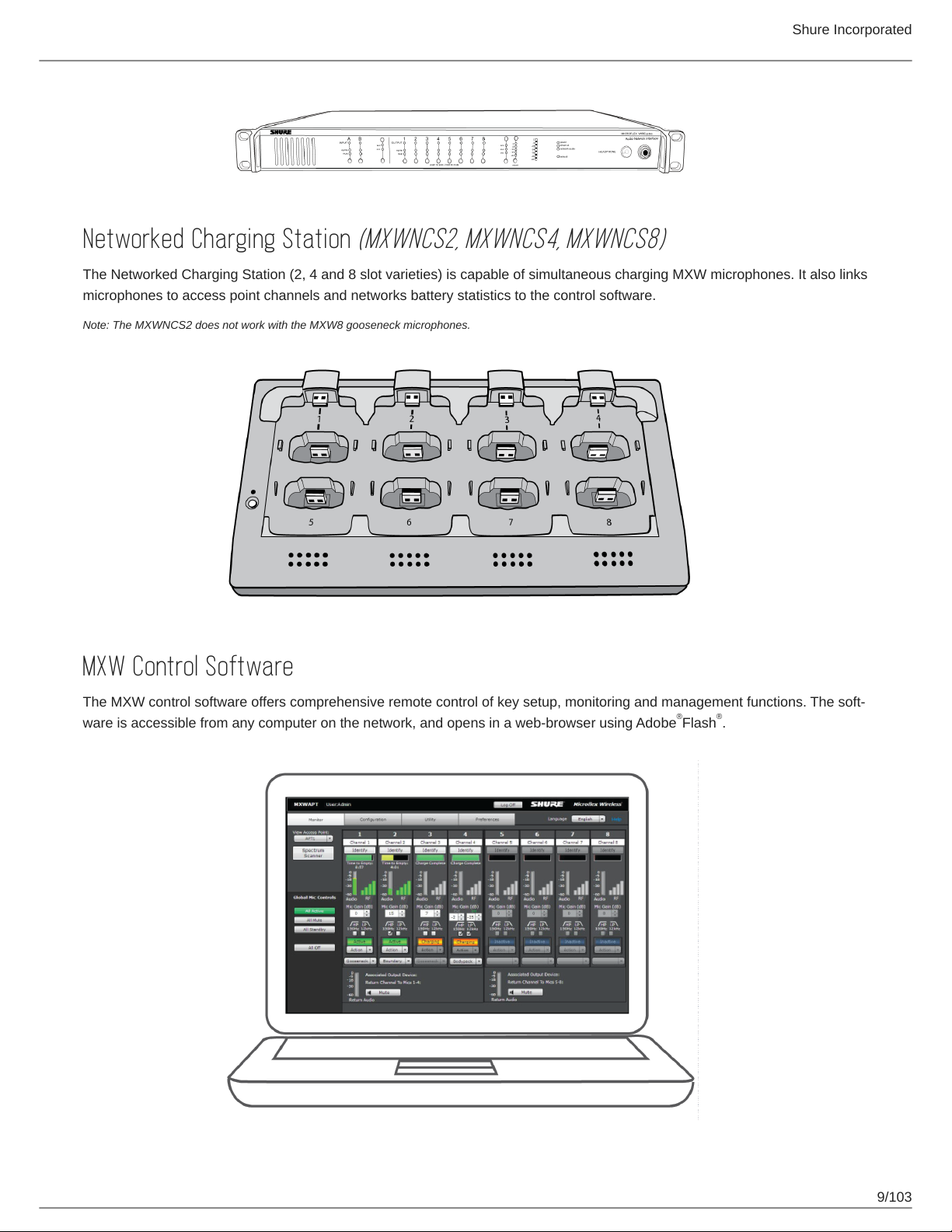
Access Point Transceiver
The Access Point Transceiver (2, 4 and 8 channel units) mounts to a wall or ceiling to manage encrypted, wireless audio con
nections with microphones. As a system hub, it transports digital audio between the wireless microphones and other Dante de
vices on the same network. The APT includes a webserver that hosts the MXW System control software, used for monitoring,
configuration, and remote control of the system.
(MXWAPT2, MXWAPT4, MXWAPT8)
Audio Network Interface
The Audio Network Interface (4 and 8 channel) is a Dante network device that provides analog audio input and outputs for the
MXW system. It has a 4-port Gigabit Ethernet switch that enables the connection of an MXW access point, a computer and up
to two MXW networked charging stations.
(MXWANI4, MXWANI8)
8/103
Shure Incorporated
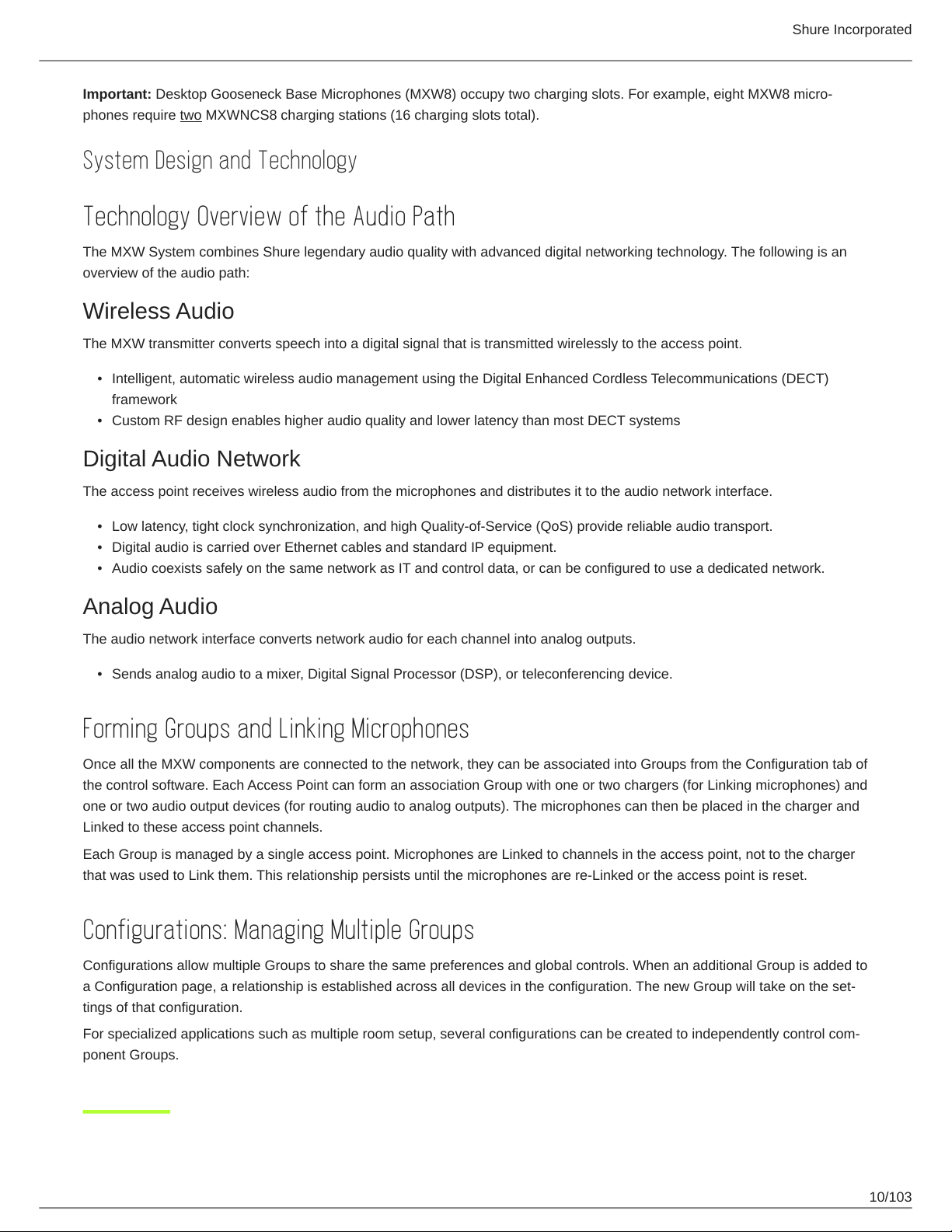
Networked Charging Station
The Networked Charging Station (2, 4 and 8 slot varieties) is capable of simultaneous charging MXW microphones. It also links
microphones to access point channels and networks battery statistics to the control software.
Note: The MXWNCS2 does not work with the MXW8 gooseneck microphones.
(MXWNCS2, MXWNCS4, MXWNCS8)
MXW Control Software
The MXW control software offers comprehensive remote control of key setup, monitoring and management functions. The soft
ware is accessible from any computer on the network, and opens in a web-browser using Adobe Flash .
® ®
9/103
Shure Incorporated
Important: Desktop Gooseneck Base Microphones (MXW8) occupy two charging slots. For example, eight MXW8 micro
phones require two MXWNCS8 charging stations (16 charging slots total).
System Design and Technology
Technology Overview of the Audio Path
The MXW System combines Shure legendary audio quality with advanced digital networking technology. The following is an
overview of the audio path:
Wireless Audio
The MXW transmitter converts speech into a digital signal that is transmitted wirelessly to the access point.
•
Intelligent, automatic wireless audio management using the Digital Enhanced Cordless Telecommunications (DECT)
framework
•
Custom RF design enables higher audio quality and lower latency than most DECT systems
Digital Audio Network
The access point receives wireless audio from the microphones and distributes it to the audio network interface.
•
Low latency, tight clock synchronization, and high Quality-of-Service (QoS) provide reliable audio transport.
•
Digital audio is carried over Ethernet cables and standard IP equipment.
•
Audio coexists safely on the same network as IT and control data, or can be configured to use a dedicated network.
Analog Audio
The audio network interface converts network audio for each channel into analog outputs.
•
Sends analog audio to a mixer, Digital Signal Processor (DSP), or teleconferencing device.
Forming Groups and Linking Microphones
Once all the MXW components are connected to the network, they can be associated into Groups from the Configuration tab of
the control software. Each Access Point can form an association Group with one or two chargers (for Linking microphones) and
one or two audio output devices (for routing audio to analog outputs). The microphones can then be placed in the charger and
Linked to these access point channels.
Each Group is managed by a single access point. Microphones are Linked to channels in the access point, not to the charger
that was used to Link them. This relationship persists until the microphones are re-Linked or the access point is reset.
Configurations: Managing Multiple Groups
Configurations allow multiple Groups to share the same preferences and global controls. When an additional Group is added to
a Configuration page, a relationship is established across all devices in the configuration. The new Group will take on the set
tings of that configuration.
For specialized applications such as multiple room setup, several configurations can be created to independently control com
ponent Groups.
10/103

Shure Incorporated
Hardware Description
Audio Network Interface (ANI)
Front Panel
① Input Channels
Adds analog line- or aux-level signals to the digital network. When the device is associated to an MXW Group, inputs are
automatically routed to Linked microphone channels (Input A to channels 1-4; Input B to 5-8).
② Output Channels
Converts digital network audio to an analog output for each channel. When associated to an MXW group, access point
channels are automatically routed to the outputs of the ANI.
③ Channel Selector
Selects a channel to perform the following functions:
Action Function
Listen to that channel at the headphone jack
Single Press
Press and Hold (3 sec
onds)
Display and adjust the channel output level and attenuation
Monitor output signal on the level meter
Mute/unmute a channel. Mute is indicated by the mute LED.
④ Selected Channel LED
Illuminates when a channel is selected.
⑤ Signal Strength LED (sig/clip)
Indicates audio signal strength for each channel:
◦
Green = Normal
◦
Amber = Strong
◦
Red = Clipping (to eliminate clipping, attenuate the signal level at the audio source)
⑥ Mute LED
Illuminates red when the channel output is muted (hold its channel select button for 3 seconds). A muted channel is still
routed to the HEADPHONE jack for monitoring or troubleshooting.
11/103
Shure Incorporated
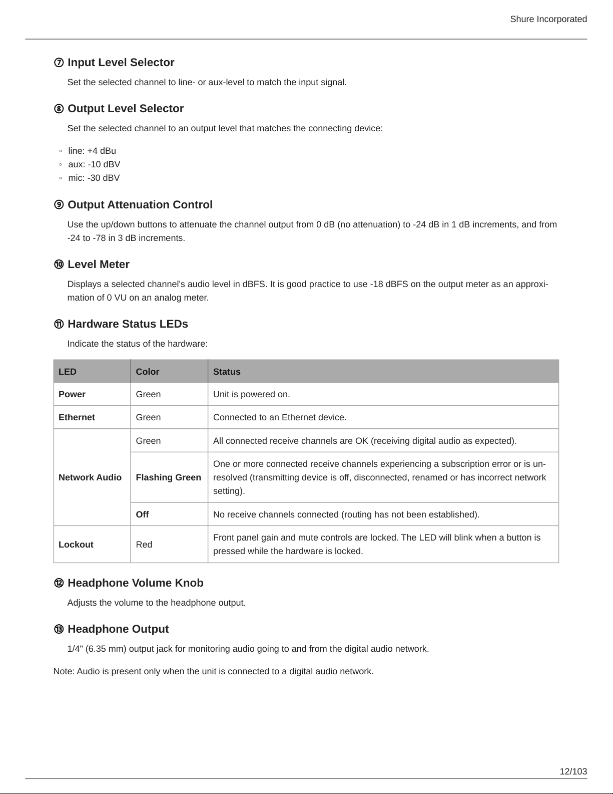
⑦ Input Level Selector
Set the selected channel to line- or aux-level to match the input signal.
⑧ Output Level Selector
Set the selected channel to an output level that matches the connecting device:
◦
line: +4 dBu
◦
aux: -10 dBV
◦
mic: -30 dBV
⑨ Output Attenuation Control
Use the up/down buttons to attenuate the channel output from 0 dB (no attenuation) to -24 dB in 1 dB increments, and from
-24 to -78 in 3 dB increments.
⑩ Level Meter
Displays a selected channel's audio level in dBFS. It is good practice to use 18 dBFS on the output meter as an approxi
mation of 0 VU on an analog meter.
⑪ Hardware Status LEDs
Indicate the status of the hardware:
LED Color Status
Power Green Unit is powered on.
Ethernet Green Connected to an Ethernet device.
Green All connected receive channels are OK (receiving digital audio as expected).
One or more connected receive channels experiencing a subscription error or is un
Network Audio
Lockout Red
Flashing Green
Off No receive channels connected (routing has not been established).
resolved (transmitting device is off, disconnected, renamed or has incorrect network
setting).
Front panel gain and mute controls are locked. The LED will blink when a button is
pressed while the hardware is locked.
⑫ Headphone Volume Knob
Adjusts the volume to the headphone output.
⑬ Headphone Output
1/4" (6.35 mm) output jack for monitoring audio going to and from the digital audio network.
Note: Audio is present only when the unit is connected to a digital audio network.
12/103
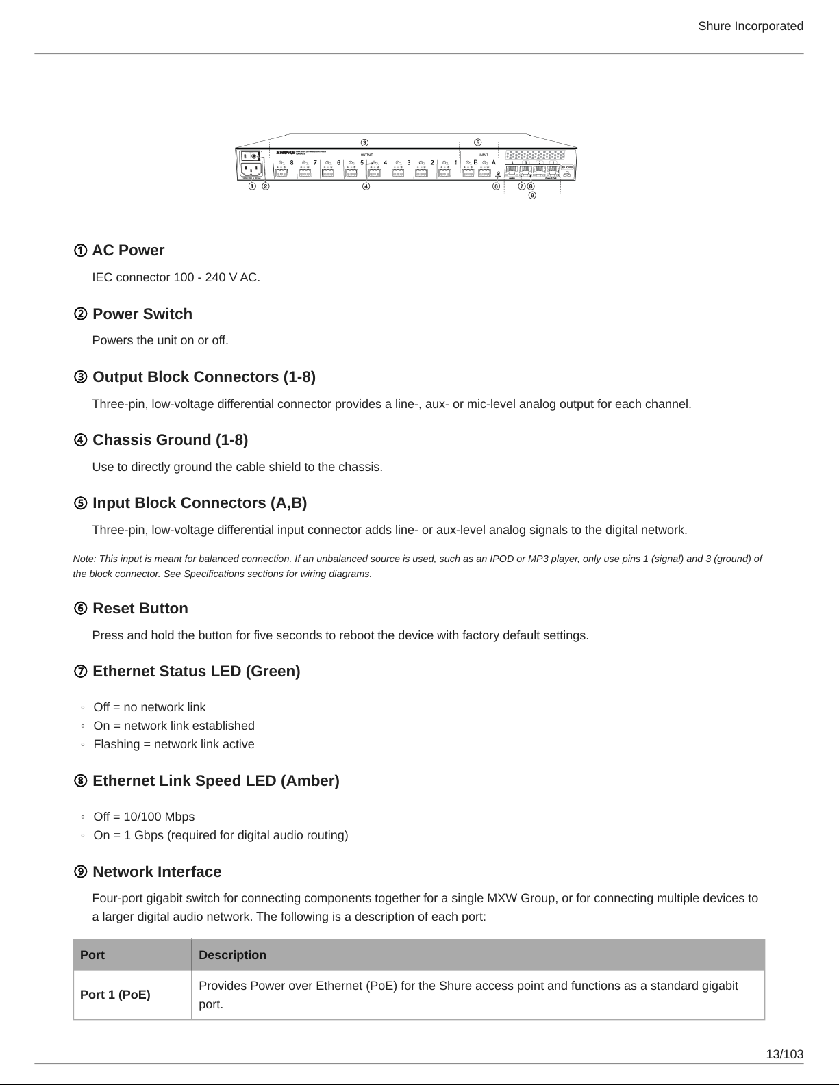
Back Panel
① AC Power
IEC connector 100 - 240 V AC.
② Power Switch
Powers the unit on or off.
③ Output Block Connectors (1-8)
Three-pin, low-voltage differential connector provides a line-, aux- or mic-level analog output for each channel.
Shure Incorporated
④ Chassis Ground (1-8)
Use to directly ground the cable shield to the chassis.
⑤ Input Block Connectors (A,B)
Three-pin, low-voltage differential input connector adds line- or aux-level analog signals to the digital network.
Note: This input is meant for balanced connection. If an unbalanced source is used, such as an IPOD or MP3 player, only use pins 1 (signal) and 3 (ground) of
the block connector. See Specifications sections for wiring diagrams.
⑥ Reset Button
Press and hold the button for five seconds to reboot the device with factory default settings.
⑦ Ethernet Status LED (Green)
◦
Off = no network link
◦
On = network link established
◦
Flashing = network link active
⑧ Ethernet Link Speed LED (Amber)
◦
Off = 10/100 Mbps
◦
On = 1 Gbps (required for digital audio routing)
⑨ Network Interface
Four-port gigabit switch for connecting components together for a single MXW Group, or for connecting multiple devices to
a larger digital audio network. The following is a description of each port:
Port Description
Port 1 (PoE)
Provides Power over Ethernet (PoE) for the Shure access point and functions as a standard gigabit
port.
13/103
Port Description
Shure Incorporated
Ports 2 and 3
Port 4 (Uplink)
Standard gigabit ports enable the connection of another MXW network, additional MXWANIs, a
MXWNCS charging stations or an external control system.
Normal mode (default): this port functions the same as ports 2 and 3.
Uplink Mode: only transports control data. This mode blocks network audio and data for Shure Web
Discovery Application, Dante Controller and Dante Virtual Soundcard.
Access Point Transceiver (APT)
The access point transceiver is the hub of the audio signal flow and manages the RF stability of each microphone in the group.
The APT performs the following functions:
•
Receives and decrypts wireless audio signals from microphones in the group
•
Delivers the audio signal to the digital audio network and audio network interface (ANI)
•
Hosts an embedded web server that provides access to the control software used to manage the MXW system
•
Sends and receives control information (such as gain adjustment and link settings) between the components, MXW con
trol software and 3rd party controllers.
•
Transmits an encrypted audio signal to the microphone's headphone output for listening to translated audio or other exter
nal sources.
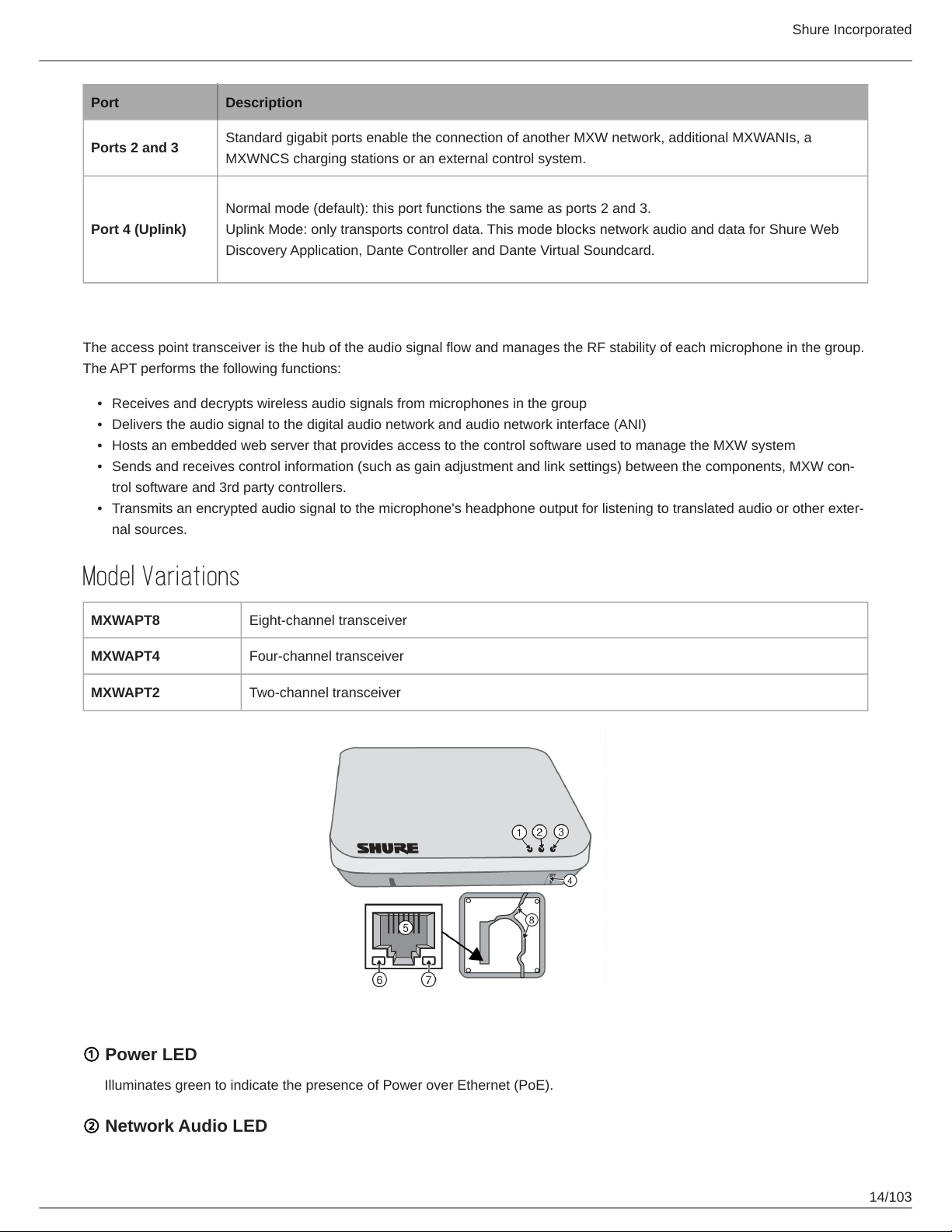
Model Variations
MXWAPT8 Eight-channel transceiver
MXWAPT4 Four-channel transceiver
MXWAPT2 Two-channel transceiver
① Power LED
Illuminates green to indicate the presence of Power over Ethernet (PoE).
② Network Audio LED
14/103
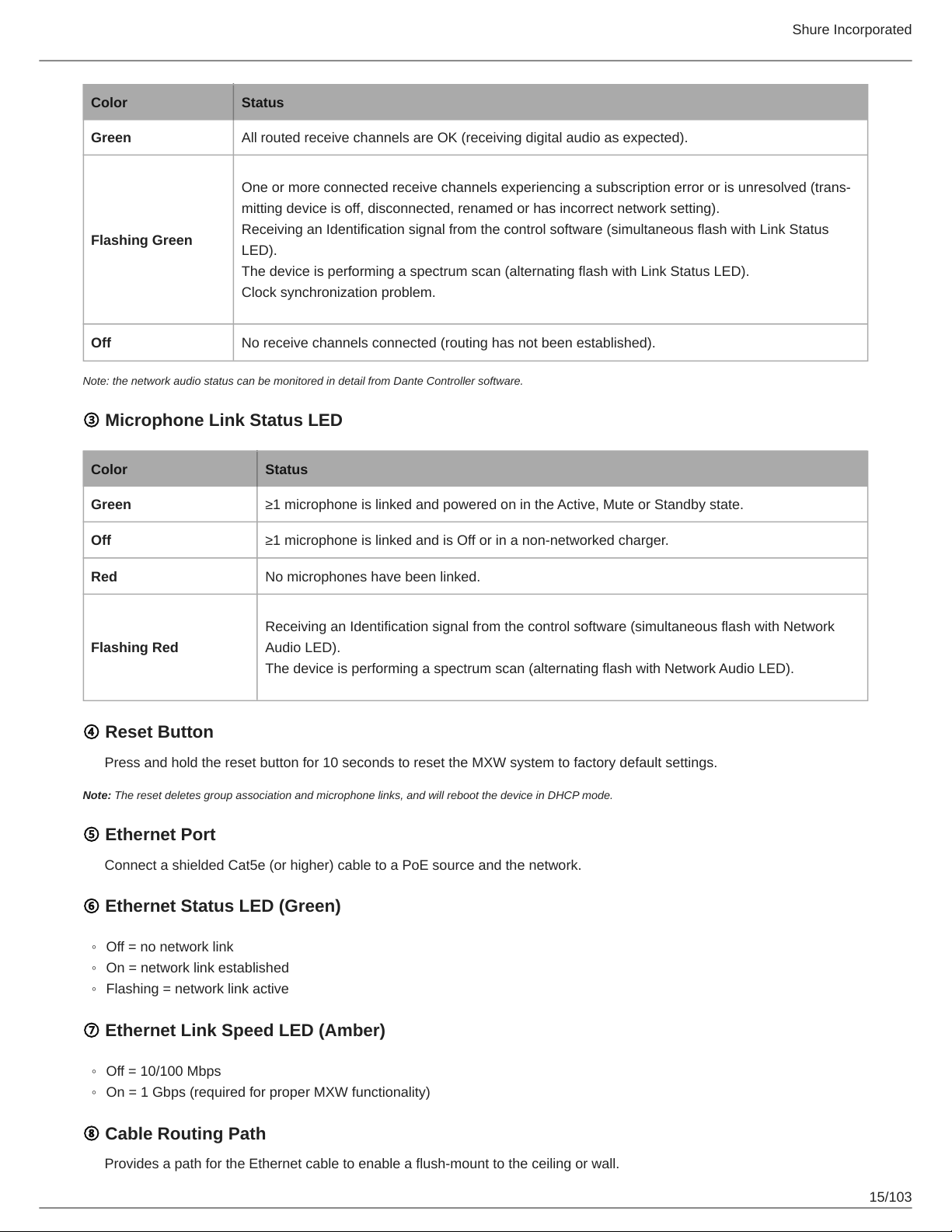
Color Status
Green All routed receive channels are OK (receiving digital audio as expected).
One or more connected receive channels experiencing a subscription error or is unresolved (trans
mitting device is off, disconnected, renamed or has incorrect network setting).
Flashing Green
Off No receive channels connected (routing has not been established).
Note: the network audio status can be monitored in detail from Dante Controller software.
Receiving an Identification signal from the control software (simultaneous flash with Link Status
LED).
The device is performing a spectrum scan (alternating flash with Link Status LED).
Clock synchronization problem.
③ Microphone Link Status LED
Color Status
Shure Incorporated
Green ≥1 microphone is linked and powered on in the Active, Mute or Standby state.
Off ≥1 microphone is linked and is Off or in a nonnetworked charger.
Red No microphones have been linked.
Receiving an Identification signal from the control software (simultaneous flash with Network
Flashing Red
Audio LED).
The device is performing a spectrum scan (alternating flash with Network Audio LED).
④ Reset Button
Press and hold the reset button for 10 seconds to reset the MXW system to factory default settings.
Note: The reset deletes group association and microphone links, and will reboot the device in DHCP mode.
⑤ Ethernet Port
Connect a shielded Cat5e (or higher) cable to a PoE source and the network.
⑥ Ethernet Status LED (Green)
◦
Off = no network link
◦
On = network link established
◦
Flashing = network link active
⑦ Ethernet Link Speed LED (Amber)
◦
Off = 10/100 Mbps
◦
On = 1 Gbps (required for proper MXW functionality)
⑧ Cable Routing Path
Provides a path for the Ethernet cable to enable a flush-mount to the ceiling or wall.
15/103
Shure Incorporated
Directional Antennas
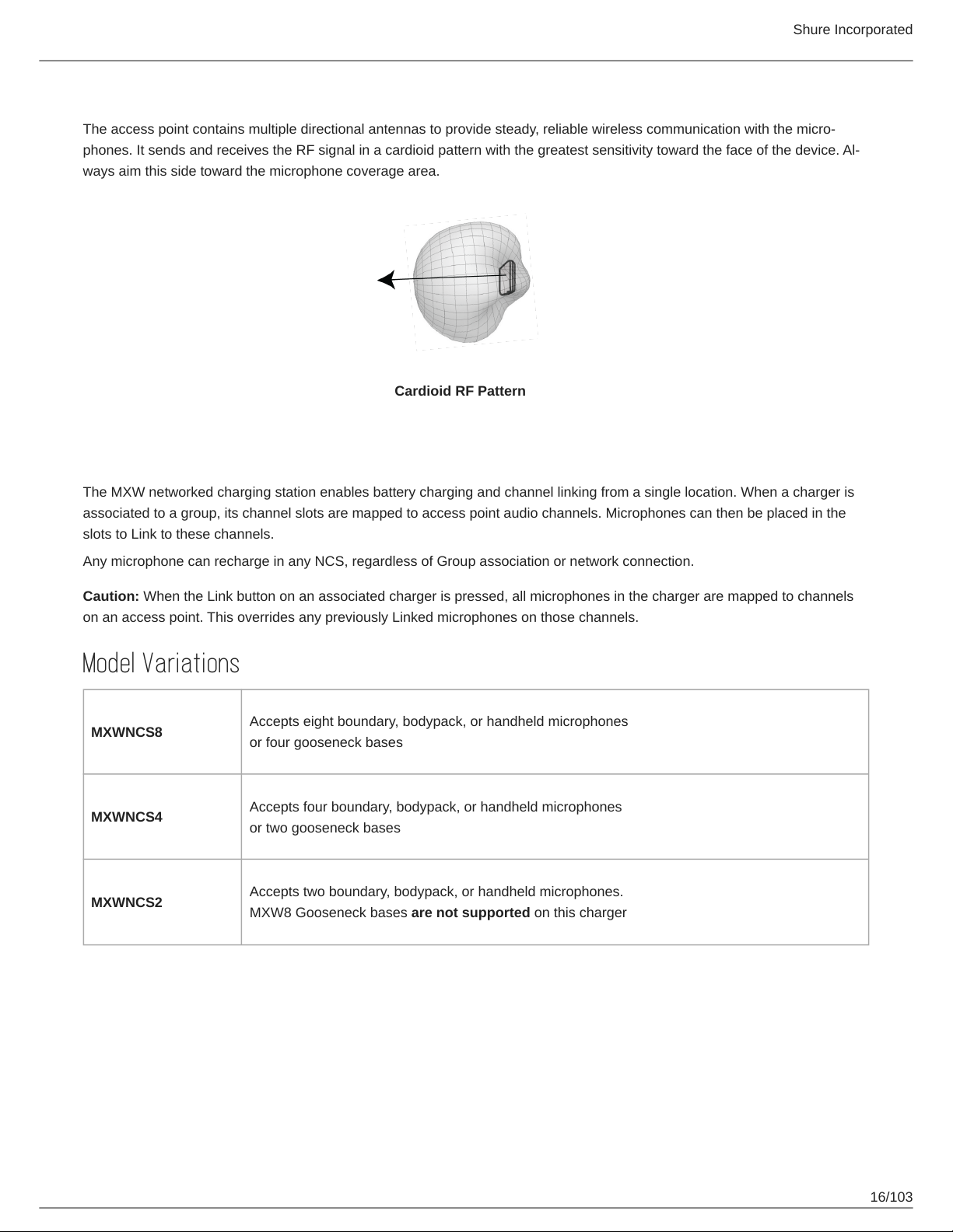
The access point contains multiple directional antennas to provide steady, reliable wireless communication with the micro
phones. It sends and receives the RF signal in a cardioid pattern with the greatest sensitivity toward the face of the device. Al
ways aim this side toward the microphone coverage area.
Cardioid RF Pattern
Networked Charger (NCS)
The MXW networked charging station enables battery charging and channel linking from a single location. When a charger is
associated to a group, its channel slots are mapped to access point audio channels. Microphones can then be placed in the
slots to Link to these channels.
Any microphone can recharge in any NCS, regardless of Group association or network connection.
Caution: When the Link button on an associated charger is pressed, all microphones in the charger are mapped to channels
on an access point. This overrides any previously Linked microphones on those channels.
Model Variations
MXWNCS8
MXWNCS4
MXWNCS2
Accepts eight boundary, bodypack, or handheld microphones
or four gooseneck bases
Accepts four boundary, bodypack, or handheld microphones
or two gooseneck bases
Accepts two boundary, bodypack, or handheld microphones.
MXW8 Gooseneck bases are not supported on this charger
16/103
Shure Incorporated
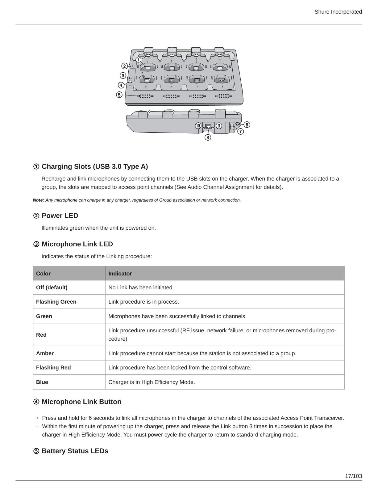
① Charging Slots (USB 3.0 Type A)
Recharge and link microphones by connecting them to the USB slots on the charger. When the charger is associated to a
group, the slots are mapped to access point channels (See Audio Channel Assignment for details).
Note: Any microphone can charge in any charger, regardless of Group association or network connection.
② Power LED
Illuminates green when the unit is powered on.
③ Microphone Link LED
Indicates the status of the Linking procedure:
Color Indicator
Off (default) No Link has been initiated.
Flashing Green Link procedure is in process.
Green Microphones have been successfully linked to channels.
Red
Amber Link procedure cannot start because the station is not associated to a group.
Flashing Red Link procedure has been locked from the control software.
Link procedure unsuccessful (RF issue, network failure, or microphones removed during pro
cedure)
Blue Charger is in High Efficiency Mode.
④ Microphone Link Button
◦
Press and hold for 6 seconds to link all microphones in the charger to channels of the associated Access Point Transceiver.
◦
Within the first minute of powering up the charger, press and release the Link button 3 times in succession to place the
charger in High Efficiency Mode. You must power cycle the charger to return to standard charging mode.
⑤ Battery Status LEDs
17/103
Shure Incorporated
Monitors the charge status of the connected microphone in increments of <10, 10, 25, 50, 75, 100% (see Batteries for more
detail). Additionally, the five LEDs flash for several seconds when the microphone has been successfully linked to the chan
nel.
⑥ Locking DC Power Supply
Secures the PS60 power supply to the input jack of the station.
⑦ Power Switch
Powers the unit on or off.
⑧ Ethernet Port
Connects to the MXW System network through an MXW Audio Network Interface or a switch using an Ethernet cable.
⑨ Ethernet Status LED (Green)
◦
Off = no network link.
◦
On = network link established.
◦
Flashing = network link active.
⑩ Ethernet Link Speed LED (Amber)
◦
Off = 10 Mbps
◦
On = 100 Mbps
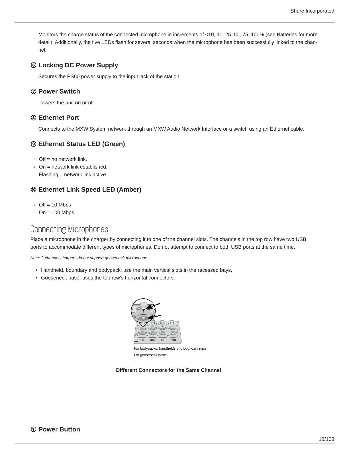
Connecting Microphones
Place a microphone in the charger by connecting it to one of the channel slots. The channels in the top row have two USB
ports to accommodate different types of microphones. Do not attempt to connect to both USB ports at the same time.
Note: 2-channel chargers do not support gooseneck microphones.
•
Handheld, boundary and bodypack: use the main vertical slots in the recessed bays.
•
Gooseneck base: uses the top row's horizontal connectors.
Different Connectors for the Same Channel
Microphone Transmitters
Description
① Power Button
18/103
Shure Incorporated
MXW6, MXW8: Press and hold the dedicated power button for three seconds to turn the transmitter on or off.
MXW1, MXW2: Press and hold the Mute/Active button for five seconds to turn the transmitter on or off.
② Mute/Active Button
Changes the audio status from Active to Mute, or Mute to Active. The button behavior for each transmitter type can be set
independently from the Preferences tab. The following describes the function of each setting:
◦
Toggle: Press and release the button to change the status to Active or Mute.
◦
Push-to-talk: Hold button to pass audio.
◦
Push-to-mute: Hold button to mute the audio.
◦
Disabled: The button does not affect the audio.
③ Status LED
Indicates the transmitter's status. The color indicators for Mute and Active can be customized from the Preferences tab. See
the Status LED table for the default LED behavior for MXW transmitters except the gooseneck light-ring models (MX405R/
410R/415R).
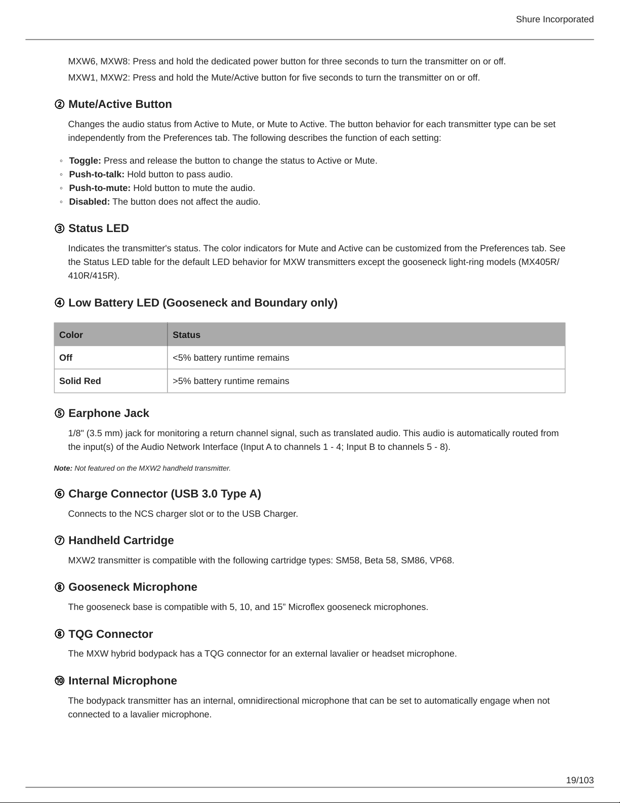
④ Low Battery LED (Gooseneck and Boundary only)
Color Status
Off <5% battery runtime remains
Solid Red >5% battery runtime remains
⑤ Earphone Jack
1/8" (3.5 mm) jack for monitoring a return channel signal, such as translated audio. This audio is automatically routed from
the input(s) of the Audio Network Interface (Input A to channels 1 - 4; Input B to channels 5 - 8).
Note: Not featured on the MXW2 handheld transmitter.
⑥ Charge Connector (USB 3.0 Type A)
Connects to the NCS charger slot or to the USB Charger.
⑦ Handheld Cartridge
MXW2 transmitter is compatible with the following cartridge types: SM58, Beta 58, SM86, VP68.
⑧ Gooseneck Microphone
The gooseneck base is compatible with 5, 10, and 15” Microflex gooseneck microphones.
⑧ TQG Connector
The MXW hybrid bodypack has a TQG connector for an external lavalier or headset microphone.
⑩ Internal Microphone
The bodypack transmitter has an internal, omnidirectional microphone that can be set to automatically engage when not
connected to a lavalier microphone.
19/103
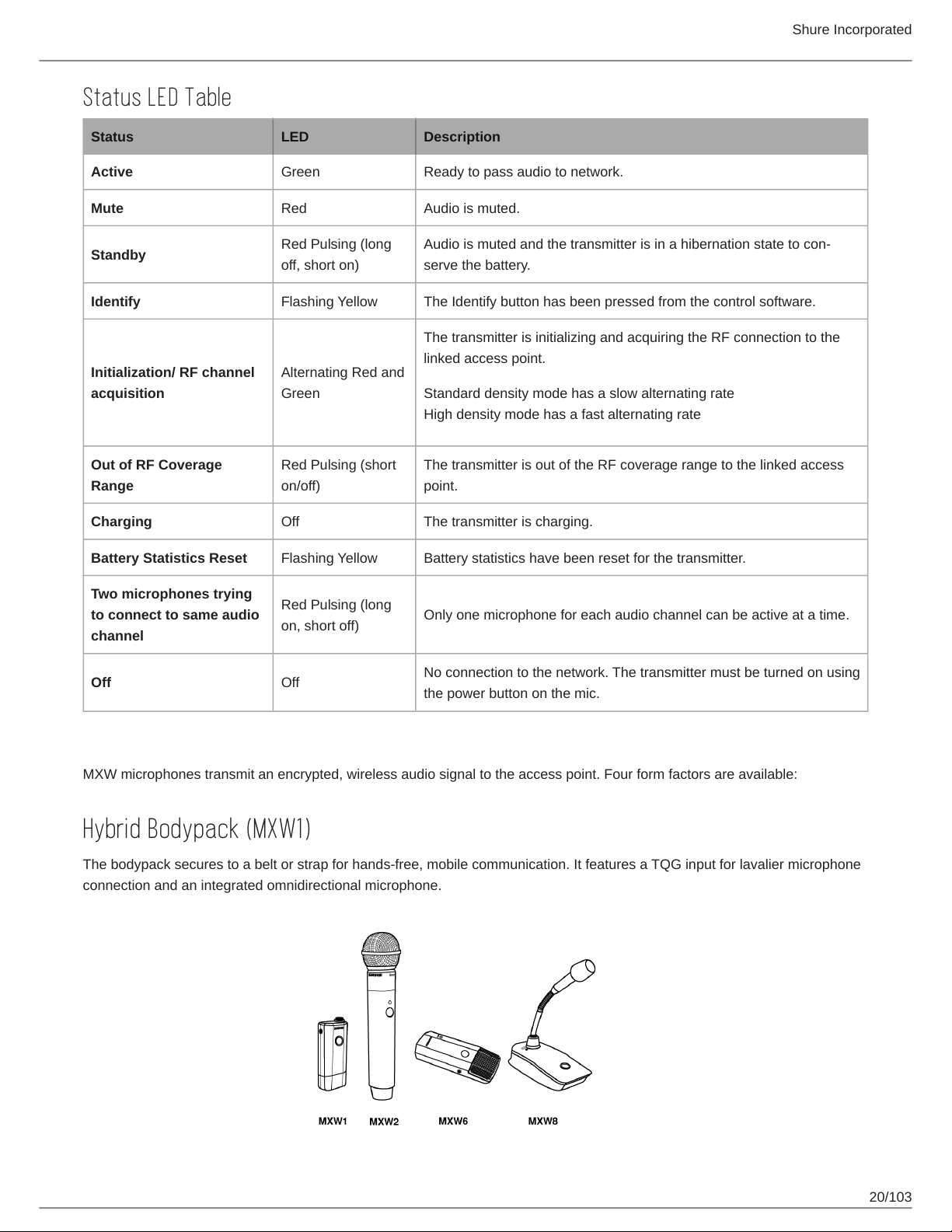
Status LED Table
Status LED Description
Active Green Ready to pass audio to network.
Mute Red Audio is muted.
Shure Incorporated
Standby
Identify Flashing Yellow The Identify button has been pressed from the control software.
Initialization/ RF channel
acquisition
Out of RF Coverage
Range
Charging Off The transmitter is charging.
Battery Statistics Reset Flashing Yellow Battery statistics have been reset for the transmitter.
Two microphones trying
to connect to same audio
channel
Off Off
Red Pulsing (long
off, short on)
Alternating Red and
Green
Red Pulsing (short
on/off)
Red Pulsing (long
on, short off)
Audio is muted and the transmitter is in a hibernation state to con
serve the battery.
The transmitter is initializing and acquiring the RF connection to the
linked access point.
Standard density mode has a slow alternating rate
High density mode has a fast alternating rate
The transmitter is out of the RF coverage range to the linked access
point.
Only one microphone for each audio channel can be active at a time.
No connection to the network. The transmitter must be turned on using
the power button on the mic.
Microphone Transmitters
MXW microphones transmit an encrypted, wireless audio signal to the access point. Four form factors are available:
Hybrid Bodypack (MXW1)
The bodypack secures to a belt or strap for hands-free, mobile communication. It features a TQG input for lavalier microphone
connection and an integrated omnidirectional microphone.
20/103
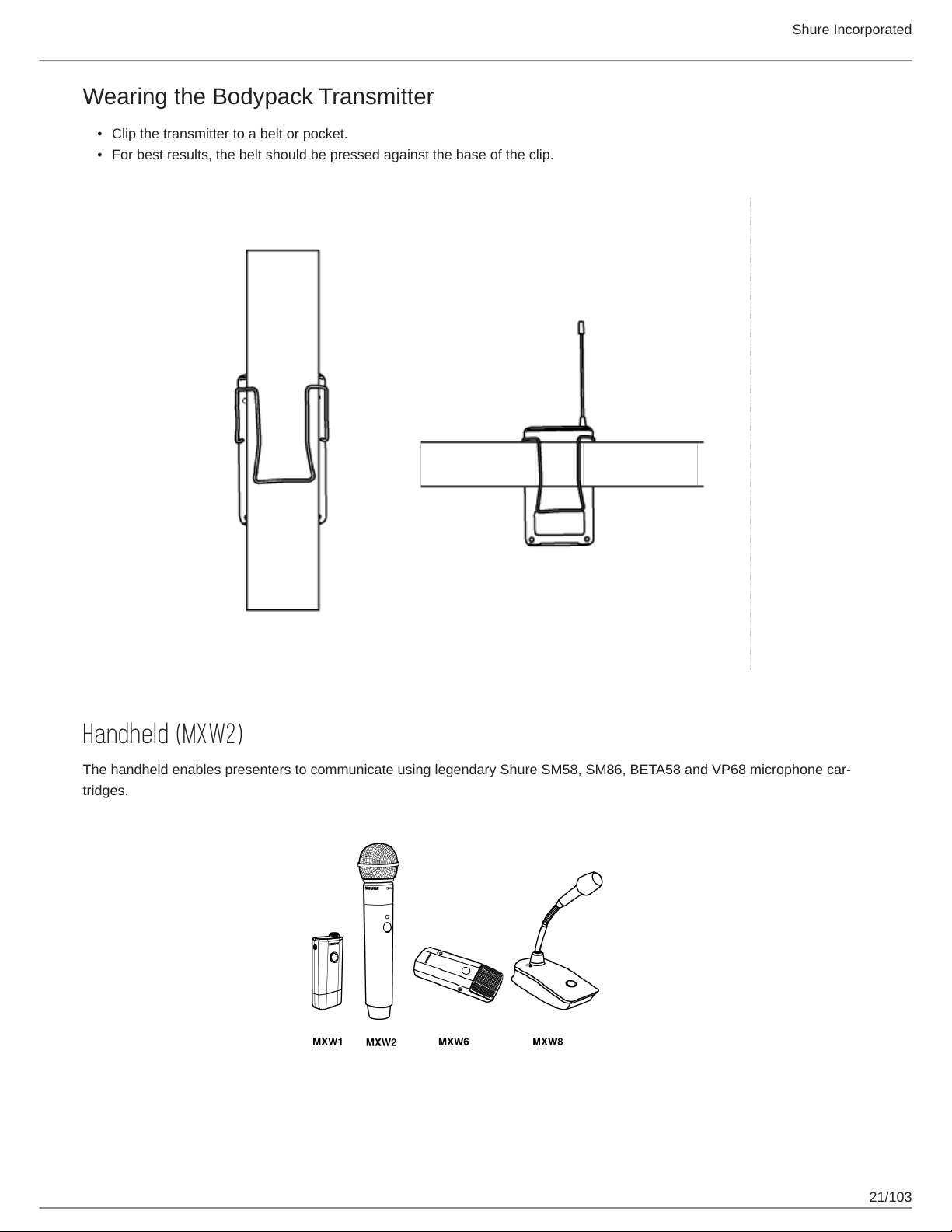
Wearing the Bodypack Transmitter
•
Clip the transmitter to a belt or pocket.
•
For best results, the belt should be pressed against the base of the clip.
Shure Incorporated
Handheld (MXW2)
The handheld enables presenters to communicate using legendary Shure SM58, SM86, BETA58 and VP68 microphone car
tridges.
21/103
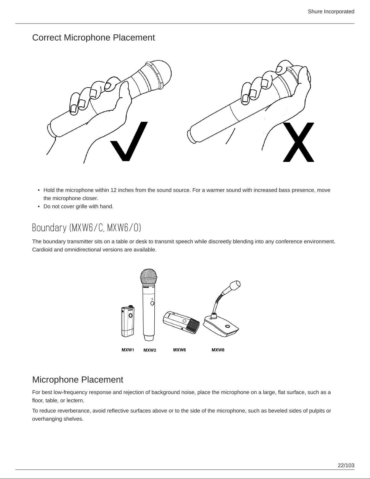
Correct Microphone Placement
Shure Incorporated
•
Hold the microphone within 12 inches from the sound source. For a warmer sound with increased bass presence, move
the microphone closer.
•
Do not cover grille with hand.
Boundary (MXW6/C, MXW6/O)
The boundary transmitter sits on a table or desk to transmit speech while discreetly blending into any conference environment.
Cardioid and omnidirectional versions are available.
Microphone Placement
For best low-frequency response and rejection of background noise, place the microphone on a large, flat surface, such as a
floor, table, or lectern.
To reduce reverberance, avoid reflective surfaces above or to the side of the microphone, such as beveled sides of pulpits or
overhanging shelves.
22/103
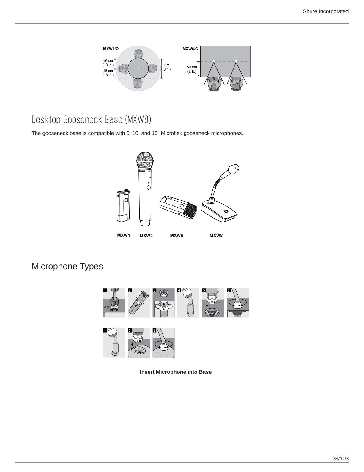
Desktop Gooseneck Base (MXW8)
The gooseneck base is compatible with 5, 10, and 15” Microflex gooseneck microphones.
Shure Incorporated
Microphone Types
Insert Microphone into Base
23/103
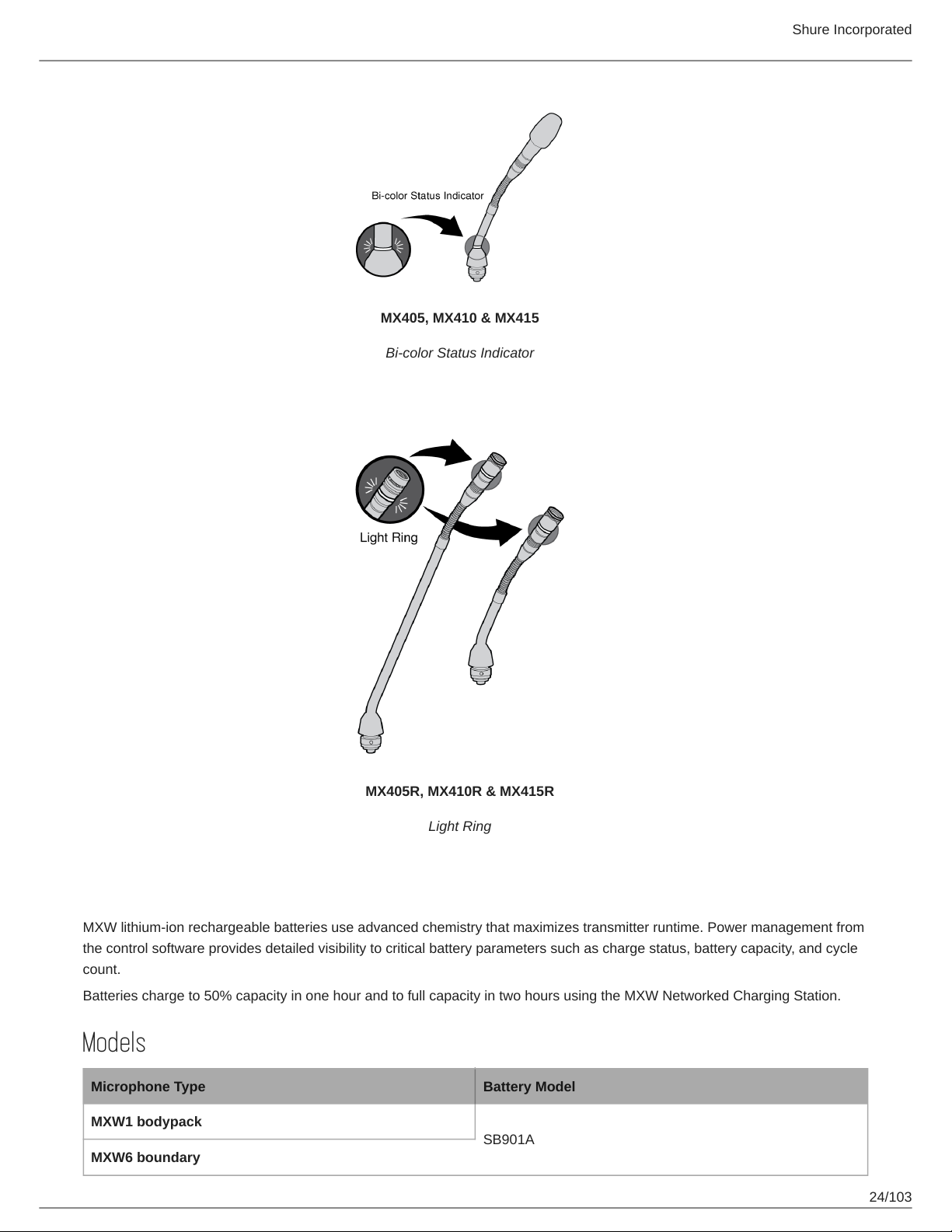
MX405, MX410 & MX415
Bi-color Status Indicator
Shure Incorporated
MX405R, MX410R & MX415R
Light Ring
Rechargeable Batteries
MXW lithium-ion rechargeable batteries use advanced chemistry that maximizes transmitter runtime. Power management from
the control software provides detailed visibility to critical battery parameters such as charge status, battery capacity, and cycle
count.
Batteries charge to 50% capacity in one hour and to full capacity in two hours using the MXW Networked Charging Station.
Models
Microphone Type Battery Model
MXW1 bodypack
SB901A
MXW6 boundary
24/103
Shure Incorporated
Microphone Type Battery Model
MXW8 gooseneck base
MXW2 handheld SB902A
Networked Charging Station (NCS)
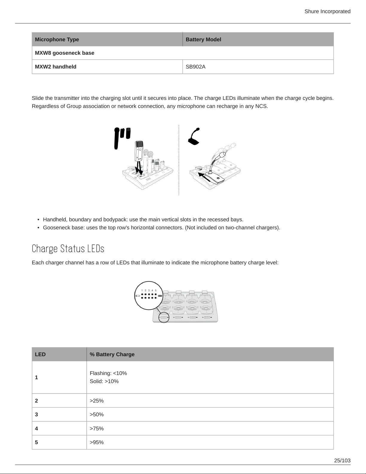
Slide the transmitter into the charging slot until it secures into place. The charge LEDs illuminate when the charge cycle begins.
Regardless of Group association or network connection, any microphone can recharge in any NCS.
•
Handheld, boundary and bodypack: use the main vertical slots in the recessed bays.
•
Gooseneck base: uses the top row's horizontal connectors. (Not included on two-channel chargers).
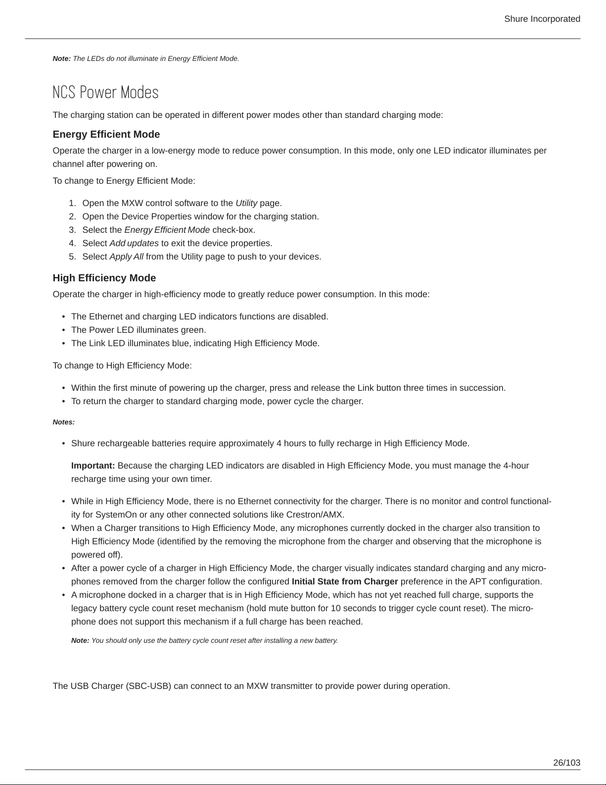
Charge Status LEDs
Each charger channel has a row of LEDs that illuminate to indicate the microphone battery charge level:
LED % Battery Charge
1
Flashing: <10%
Solid: >10%
2 >25%
3 >50%
4 >75%
5 >95%
25/103
Shure Incorporated
Note: The LEDs do not illuminate in Energy Efficient Mode.
NCS Power Modes
The charging station can be operated in different power modes other than standard charging mode:
Energy Efficient Mode
Operate the charger in a low-energy mode to reduce power consumption. In this mode, only one LED indicator illuminates per
channel after powering on.
To change to Energy Efficient Mode:
1.
Open the MXW control software to the Utility page.
2.
Open the Device Properties window for the charging station.
3.
Select the Energy Efficient Mode check-box.
4.
Select Add updates to exit the device properties.
5.
Select Apply All from the Utility page to push to your devices.
High Efficiency Mode
Operate the charger in high-efficiency mode to greatly reduce power consumption. In this mode:
•
The Ethernet and charging LED indicators functions are disabled.
•
The Power LED illuminates green.
•
The Link LED illuminates blue, indicating High Efficiency Mode.
To change to High Efficiency Mode:
•
Within the first minute of powering up the charger, press and release the Link button three times in succession.
•
To return the charger to standard charging mode, power cycle the charger.
Notes:
•
Shure rechargeable batteries require approximately 4 hours to fully recharge in High Efficiency Mode.
Important: Because the charging LED indicators are disabled in High Efficiency Mode, you must manage the 4-hour
recharge time using your own timer.
•
While in High Efficiency Mode, there is no Ethernet connectivity for the charger. There is no monitor and control functional
ity for SystemOn or any other connected solutions like Crestron/AMX.
•
When a Charger transitions to High Efficiency Mode, any microphones currently docked in the charger also transition to
High Efficiency Mode (identified by the removing the microphone from the charger and observing that the microphone is
powered off).
•
After a power cycle of a charger in High Efficiency Mode, the charger visually indicates standard charging and any micro
phones removed from the charger follow the configured Initial State from Charger preference in the APT configuration.
•
A microphone docked in a charger that is in High Efficiency Mode, which has not yet reached full charge, supports the
legacy battery cycle count reset mechanism (hold mute button for 10 seconds to trigger cycle count reset). The micro
phone does not support this mechanism if a full charge has been reached.
Note: You should only use the battery cycle count reset after installing a new battery.
USB Charger
The USB Charger (SBC-USB) can connect to an MXW transmitter to provide power during operation.
26/103
Shure Incorporated
Battery Statistics on Control Software
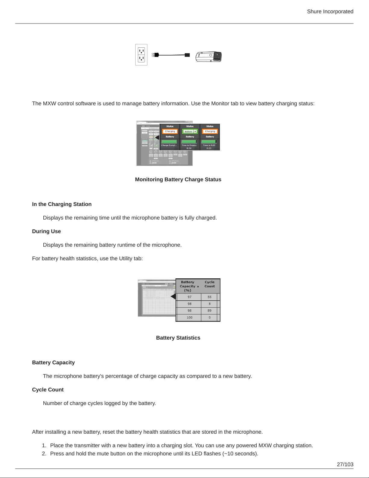
The MXW control software is used to manage battery information. Use the Monitor tab to view battery charging status:
Monitoring Battery Charge Status
In the Charging Station
Displays the remaining time until the microphone battery is fully charged.
During Use
Displays the remaining battery runtime of the microphone.
For battery health statistics, use the Utility tab:
Battery Statistics
Battery Capacity
The microphone battery's percentage of charge capacity as compared to a new battery.
Cycle Count
Number of charge cycles logged by the battery.
Reset the Microphone Battery Statistics
After installing a new battery, reset the battery health statistics that are stored in the microphone.
1.
Place the transmitter with a new battery into a charging slot. You can use any powered MXW charging station.
2.
Press and hold the mute button on the microphone until its LED flashes (~10 seconds).
27/103
Shure Incorporated
Caution: Securely hold the microphone while pressing the button to avoid damaging the USB ports on the charging
station.
Maximizing Battery Life
While the rechargeable LiIon batteries for MXW transmitters are designed to last up to 9 hours on a charge, variance in bat
tery health and use-case may result in significant differences in battery runtime. Specifically, consistency and overall runtime
decrease with the number of charge cycles. Battery health of 80% or less is an indicator that a battery is nearing or at the end
of its designated life cycle and should be replaced. Health percentage and number of charge cycles are available from MXW
control software > Utility tab.
The MXW system's secondary link slots allow you to prepare alternate microphones to swap in if battery levels get low, to en
sure variable battery runtime does not cause audio interruptions. However, the following system adjustments can help get the
most runtime out of your batteries.
External LED Control
Having LEDs constantly indicate the microphone state can use a significant amount of battery power. Setting transmitters to
External LED Control disables the built-in LED except when activated by external commands via the TCPI (third-party control
interface). Maximize battery runtime by disabling the LED completely, or by setting the LED to only indicate when the micro
phone is not in its usual use state.
LED control is set from MXW control software > Preferences tab.
High Density Mode
High Density (HD) mode reallocates system resources to create additional channels when needed. In applications where laten
cy, back-channel audio monitoring, and filter control aren't major considerations, switching to HD mode can also provide up to
an hour of additional battery runtime.
Density mode is set from MXW control software > Utility tab > [desired APT] > Edit.
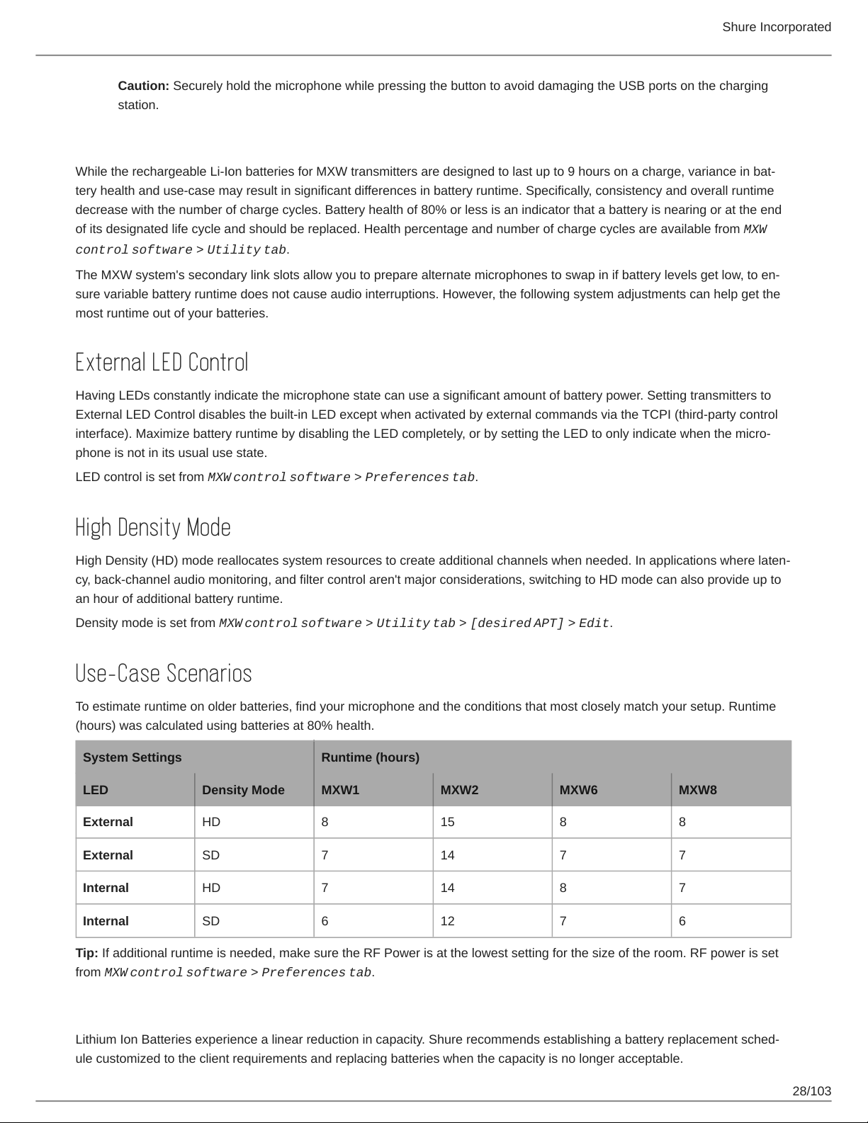
Use-Case Scenarios
To estimate runtime on older batteries, find your microphone and the conditions that most closely match your setup. Runtime
(hours) was calculated using batteries at 80% health.
System Settings Runtime (hours)
LED Density Mode MXW1 MXW2 MXW6 MXW8
External HD 8 15 8 8
External SD 7 14 7 7
Internal HD 7 14 8 7
Internal SD 6 12 7 6
Tip: If additional runtime is needed, make sure the RF Power is at the lowest setting for the size of the room. RF power is set
from MXW control software > Preferences tab.
Battery Replacement
Lithium Ion Batteries experience a linear reduction in capacity. Shure recommends establishing a battery replacement sched
ule customized to the client requirements and replacing batteries when the capacity is no longer acceptable.
28/103
Shure Incorporated
Important: After installing a new battery, reset the battery health statistics that are stored in the microphone following the steps
in Reset the Microphone Battery Statistics in the previous section.
MXW1, MXW6, MXW8 Battery Replacement
1.
Unscrew and open the battery door on the bottom of the transmitter.
2.
Remove battery by gently disconnecting the battery connector from the transmitter.
3.
Connect the replacement battery's connector to the transmitter.
4.
Replace the battery with the label facing out.
5.
Close the door and tighten the screw.
6.
Dispose of batteries properly. Check with your local vendor for proper disposal of used batteries.
MXW2 Battery Replacement
1.
Unscrew the two screws at the bottom of the transmitter handle.
2.
Unscrew and remove the microphone head.
3.
Remove the retention clip and gently pull out the battery frame.
4.
Unscrew the three screws that fasten the battery door to the frame. Remove the battery door.
5.
Replace the old battery with a new one.
6.
Replace the battery door and tighten the screws.
7.
Gently slide the battery frame back into the transmitter.
8.
Replace the retention clip to secure the battery frame in the transmitter.
9.
Replace the microphone head. Make sure it is secure.
10.
Replace the two screws on the bottom of the transmitter handle.
11.
Dispose of batteries properly. Check with your local vendor for proper disposal of used batteries.
Installation
Additional Equipment
Network Cables
Audio Cables
Use shielded Cat5e (or higher) Ethernet cables, limiting cable runs to 100 meters maximum
between network devices.
Reference the hardware kit user guide supplied with the MXW Audio Network Interface to
assemble audio cables to the connectors.
29/103
Gigabit DHCP Router (sys
tems with >1 APT)
Shure Incorporated
For systems with more than one APT, a DHCP router is recommended to connect equip
ment. Ensure that it meets the following requirements:
•
Gigabit ports
•
Provides Class 0 PoE with at least 6.5W (for powering the MXWAPT)
•
Quality of Service (QoS) with 4 queues
•
Diffserv (DSCP) QoS, with strict priority
•
If the router features Energy Efficient Ethernet (or Green Ethernet), ensure it is disabled
from the ports dedicated for the MXW system.
•
Recommended: A managed switch to provide detailed information about the operation
of each network link: port speed, error counters, bandwidth used, etc.
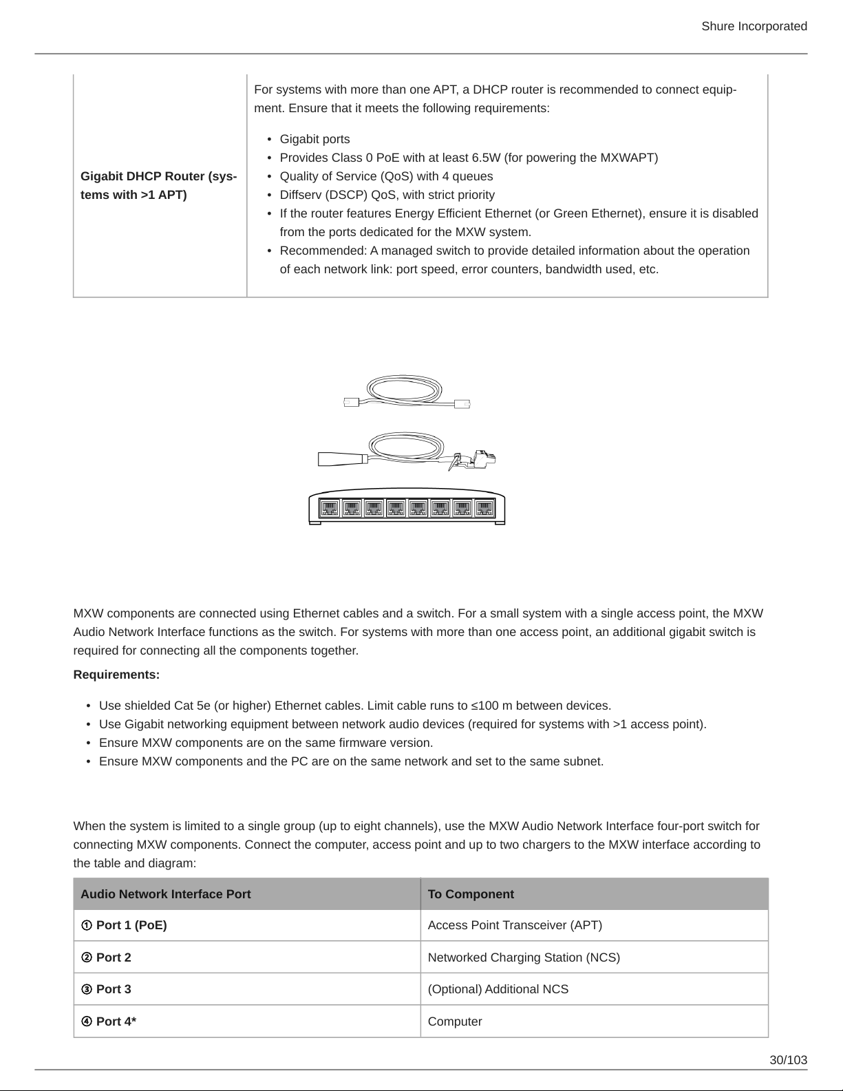
Connecting MXW Components
MXW components are connected using Ethernet cables and a switch. For a small system with a single access point, the MXW
Audio Network Interface functions as the switch. For systems with more than one access point, an additional gigabit switch is
required for connecting all the components together.
Requirements:
•
Use shielded Cat 5e (or higher) Ethernet cables. Limit cable runs to ≤100 m between devices.
•
Use Gigabit networking equipment between network audio devices (required for systems with >1 access point).
•
Ensure MXW components are on the same firmware version.
•
Ensure MXW components and the PC are on the same network and set to the same subnet.
Single Group System (1 Access Point)
When the system is limited to a single group (up to eight channels), use the MXW Audio Network Interface four-port switch for
connecting MXW components. Connect the computer, access point and up to two chargers to the MXW interface according to
the table and diagram:
Audio Network Interface Port To Component
① Port 1 (PoE) Access Point Transceiver (APT)
② Port 2 Networked Charging Station (NCS)
③ Port 3 (Optional) Additional NCS
④ Port 4* Computer
30/103
 Loading...