

Page 1
MXW Wireless
10/02/12
Conference System
©2012 Shure Incorporated
27WG20831 (Rev. 1)
Page 2

10/02/12
Page 3
IMPORTANT SAFETY INSTRUCTIONS
10/02/12
1. READ these instructions.
2. KEEP these instructions.
3. HEED all warnings.
4. FOLLOW all instructions.
5. DO NOT use this apparatus near water.
6. CLEAN ONLY with dry cloth.
7. DO NOT block any ventilation openings. Allow sufficient distances for adequate ventilation and install in accordance with the manufacturer’s instructions.
8. DO NOT install near any heat sources such as open flames, radiators, heat registers,
stoves, or other apparatus (including amplifiers) that produce heat. Do not place any open
flame sources on the product.
9. DO NOT defeat the safety purpose of the polarized or groundingtype plug. A polarized
plug has two blades with one wider than the other. A grounding type plug has two blades
and a third grounding prong. The wider blade or the third prong are provided for your
safety. If the provided plug does not fit into your outlet, consult an electrician for replacement of the obsolete outlet.
10. PROTECT the power cord from being walked on or pinched, particularly at plugs, convenience receptacles, and the point where they exit from the apparatus.
11. ONLY USE attachments/accessories specified by the manufacturer.
12. USE only with a cart, stand, tripod, bracket, or table specified by the manufacturer, or sold with the apparatus. When a cart is used, use caution when
moving the cart/apparatus combination to avoid injury from tip-over.
13. UNPLUG this apparatus during lightning storms or when unused for long
periods of time.
14. REFER all servicing to qualified service personnel. Servicing is required when the apparatus has been damaged in any way, such as power supply cord or plug is damaged,
liquid has been spilled or objects have fallen into the apparatus, the apparatus has been
exposed to rain or moisture, does not operate normally, or has been dropped.
15. DO NOT expose the apparatus to dripping and splashing. DO NOT put objects filled with
liquids, such as vases, on the apparatus.
16. The MAINS plug or an appliance coupler shall remain readily operable.
17. The airborne noise of the Apparatus does not exceed 70dB (A).
18. Apparatus with CLASS I construction shall be connected to a MAINS socket outlet with a
protective earthing connection.
19. To reduce the risk of fire or electric shock, do not expose this apparatus to rain or
moisture.
20. Do not attempt to modify this product. Doing so could result in personal injury and/or
product failure.
21. Operate this product within its specified operating temperature range.
This symbol indicates that dangerous voltage constituting a risk of
electric shock is present within this unit.
This symbol indicates that there are important operating and maintenance instructions in the literature accompanying this unit.
WARNING: This product contains a chemical known to the State of California to cause cancer and birth
defects or other reproductive harm.
INSTRUCCIONES IMPORTANTES DE SEGURIDAD
1. LEA estas instrucciones.
2. CONSERVE estas instrucciones.
3. PRESTE ATENCION a todas las advertencias.
4. SIGA todas las instrucciones.
5. NO utilice este aparato cerca del agua.
6. LIMPIE UNICAMENTE con un trapo seco.
7. NO obstruya ninguna de las aberturas de ventilación. Deje espacio suficiente para
proporcionar ventilación adecuada e instale los equipos según las instrucciones del
fabricante.
8. NO instale el aparato cerca de fuentes de calor tales como llamas descubiertas, radiadores, registros de calefacción, estufas u otros aparatos (incluyendo amplificadores) que
produzcan calor. No coloque artículos con llamas descubiertas en el producto.
9. NO anule la función de seguridad del enchufe polarizado o con clavija de puesta a tierra.
Un enchufe polarizado tiene dos patas, una más ancha que la otra. Un enchufe con puesta a tierra tiene dos patas y una tercera clavija con puesta a tierra. La pata más ancha
o la tercera clavija se proporciona para su seguridad. Si el tomacorriente no es del tipo
apropiado para el enchufe, consulte a un electricista para que sustituya el tomacorriente
de estilo anticuado.
10. PROTEJA el cable eléctrico para evitar que personas lo pisen o estrujen, particularmente
en sus enchufes, en los tomacorrientes y en el punto en el cual sale del aparato.
11. UTILICE únicamente los accesorios especificados por el fabricante.
12. UTILICE únicamente con un carro, pedestal, trípode, escuadra o mesa del
tipo especificado por el fabricante o vendido con el aparato. Si se usa un
carro, el mismo debe moverse con sumo cuidado para evitar que se vuelque
con el aparato.
ISTRUZIONI IMPORTANTI PER LA SICUREZZA
1. LEGGETE queste istruzioni.
2. CONSERVATELE.
3. OSSERVATE tutte le avvertenze.
4. SEGUITE tutte le istruzioni.
5. NON usate questo apparecchio vicino all'acqua.
6. PULITE l'apparecchio SOLO con un panno asciutto.
7. NON ostruite alcuna apertura per l'aria di raffreddamento. Consentite distanze sufficienti
per un'adeguata ventilazione e installate l'apparecchio seguendo le istruzioni del costruttore.
8. NON installate l'apparecchio accanto a fonti di calore, quali fiamme libere, radiatori, aperture per l'efflusso di aria calda, forni o altri apparecchi (amplificatori inclusi) che generano
calore. Non esponete il prodotto a fonti di calore non controllate.
9. NON modificate la spina polarizzata o con spinotto di protezione per non alterarne
la funzione di sicurezza. Una spina polarizzata è dotata di due lame, una più ampia
dell'altra. Una spina con spinotto è dotata di due lame e di un terzo polo di messa a terra.
La lama più ampia ed il terzo polo hanno lo scopo di tutelare la vostra incolumità. Se la
spina in dotazione non si adatta alla presa di corrente, rivolgetevi ad un elettricista per far
eseguire le modifiche necessarie.
10. EVITATE di calpestare il cavo di alimentazione o di comprimerlo, specie in corrispondenza di spine, prese di corrente e punto di uscita dall'apparecchio.
11. USATE ESCLUSIVAMENTE i dispositivi di collegamento e gli accessori
specificati dal costruttore.
12. USATE l'apparecchio solo con carrelli, sostegni, treppiedi, staffe o tavoli
specificati dal produttore o venduti unitamente all'apparecchio stesso. Se usate un carrello, fate attenzione quando lo spostate con l'apparecchio collocato
su di esso, per evitare infortuni causati da un eventuale ribaltamento del carrello stesso.
13. DESENCHUFE el aparato durante las tormentas eléctricas, o si no va a ser utilizado por
un lapso prolongado.
14. TODA reparación debe ser llevada a cabo por técnicos calificados. El aparato requiere
reparación si ha sufrido cualquier tipo de daño, incluyendo los daños al cordón o enchufe
eléctrico, si se derrama líquido sobre el aparato o si caen objetos en su interior, si ha sido
expuesto a la lluvia o la humedad, si no funciona de modo normal, o si se ha caído.
15. NO exponga este aparato a chorros o salpicaduras de líquidos. NO coloque objetos
llenos con líquido, tales como floreros, sobre el aparato.
16. El enchufe de alimentación o un acoplador para otros aparatos deberá permanecer en
buenas condiciones de funcionamiento.
17. El nivel de ruido transmitido por el aire del aparato no excede de 70 dB(A).
18. Los aparatos de fabricación CLASE I deberán conectarse a un tomacorriente de ALIMENTACION con clavija de puesta a tierra protectora.
19. Para reducir el riesgo de causar un incendio o sacudidas eléctricas, no exponga este
aparato a la lluvia ni a humedad.
20. No intente modificar este producto. Hacerlo podría causar lesiones personales y/o la falla
del producto.
21. Utilice este producto únicamente dentro de la gama de temperaturas de funcionamiento
especificadas.
Este símbolo indica que la unidad contiene niveles de voltaje peligrosos
que representan un riesgo de choques eléctricos.
Este símbolo indica que la literatura que acompaña a esta unidad contiene instrucciones importantes de funcionamiento y mantenimiento.
13. Durante i temporali o in caso di inutilizzo prolungato dell'apparecchio, SCOLLEGATELO
dalla presa di corrente.
14. Per qualsiasi intervento, RIVOLGETEVI a personale di assistenza qualificato. È necessario intervenire sull'apparecchio ogniqualvolta è stato danneggiato, in qualsiasi modo;
ad esempio la spina o il cavo di alimentazione sono danneggiati, si è versato liquido
sull'apparecchio o sono caduti oggetti su di esso, l'apparecchio è stato esposto alla pioggia o all'umidità, non funziona normalmente o è caduto.
15. NON esponete l'apparecchio a sgocciolamenti o spruzzi. NON appoggiate
sull'apparecchio oggetti pieni di liquidi, ad esempio vasi da fiori.
16. La spina ELETTRICA o l'accoppiatore per elettrodomestici deve restare prontamente
utilizzabile.
17. Il rumore aereo dell'apparecchio non supera i 70 dB (A).
18. L'apparecchio appartenente alla CLASSE I deve essere collegato ad una presa elettrica
dotata di messa a terra di protezione.
19. Per ridurre il rischio di incendio o folgorazione, non esponete questo apparecchio alla
pioggia o all'umidità.
20. Non tentate di modificare il prodotto. Tale operazione può causare infortuni e/o il guasto
del prodotto stesso.
21. Utilizzate questo prodotto entro la gamma di temperatura operativa specificata.
Questo simbolo indica la presenza di alta tensione all'interno
dell'apparecchio, che comporta il rischio di folgorazione.
Questo simbolo indica la presenza di istruzioni importanti per l'uso e la
manutenzione nella documentazione in dotazione all'apparecchio.
Page 4
ВАЖНЫЕ ИНСТРУКЦИИ ПО ТЕХНИКЕ БЕЗОПАСНОСТИ
10/02/12
1. ПРОЧИТАЙТЕ эти инструкции.
2. СОХРАНИТЕ эти инструкции.
3. ОБРАЩАЙТЕ ВНИМАНИЕ на все предупреждения.
4. СЛЕДУЙТЕ всем инструкциям.
5. НЕ пользуйтесь этим прибором вблизи воды.
6. ЧИСТИТЕ ТОЛЬКО сухой тканью.
7. НЕ закрывайте никакие вентиляционные отверстия. Оставляйте расстояния, нужные
для достаточной вентиляции, и выполняйте установку в соответствии с инструкциями
изготовителя.
8. НЕ устанавливайте вблизи каких бы то ни было источников тепла — открытого
пламени, радиаторов, обогревателей, печей или других приборов (включая усилители),
выделяющих тепло. Не помещайте на изделие источники открытого пламени.
9. НЕ пренебрегайте защитными свойствами поляризованной или заземляющей вилки.
Поляризованная вилка имеет два ножевых контакта, из которых один шире другого.
Заземляющая вилка имеет два ножевых контакта и третий, заземляющий, штырь.
Более широкий контакт или третий штырь предусматриваются для безопасности. Если
вилка прибора не подходит к вашей розетке, обратитесь к электрику для замены
розетки устаревшей конструкции.
10. ЗАЩИТИТЕ силовой шнур, чтобы на него не наступали и чтобы он не был пережат,
особенно в местах подсоединения к вилкам, розеткам и в месте выхода из прибора.
11. ИСПОЛЬЗУЙТЕ ТОЛЬКО те принадлежности и приспособления, которые
предусмотрены изготовителем.
12. ИСПОЛЬЗУЙТЕ только с тележкой, стендом, штативом, кронштейном или
столом, которые предусмотрены изготовителем или наглухо прикреплены к
прибору. При использовании тележки будьте осторожны, когда передвигаете
тележку вместе с прибором — переворачивание может привести к травме.
13. ОТСОЕДИНЯЙТЕ прибор ОТ СЕТИ во время грозы или если он не используется
длительное время.
14. ПОРУЧИТЕ все обслуживание квалифицированному техническому персоналу.
Обслуживание требуется при каком-либо повреждении прибора, например, при
повреждении шнура питания или вилки, если на прибор была пролита жидкость или
на него упал какой-либо предмет, если прибор подвергся воздействию дождя или
сырости, не функционирует нормально или если он падал.
15. НЕ допускайте попадания на прибор капель или брызг. НЕ ставьте на прибор сосуды
с жидкостью, например, вазы.
16. Вилка электропитания или штепсель прибора должны быть легко доступны.
17. Уровень воздушного шума этого аппарата не превышает 70 дБ (A).
18. Аппараты конструкции КЛАССА I необходимо подсоединять к СЕТЕВОЙ розетке с
защитным соединением для заземления.
19. Чтобы уменьшить риск возгорания или поражения электрическим током, не
допускайте попадания на этот аппарат дождя или влаги.
20. Не пытайтесь вносить изменения в это изделие. Это может привести к травме и (или)
выходу изделия из строя.
21. Эксплуатируйте это изделие в указанном диапазоне рабочих температур.
Этот знак показывает, что внутри прибора имеется опасное
напряжение, создающее риск электрического удара.
Этот знак показывает, что в сопроводительной документации
к прибору есть важные указания по его эксплуатации и
обслуживанию.
IMPORTANTES INSTRUÇÕES DE SEGURANÇA
1. LEIA estas instruções.
2. GUARDE estas instruções.
3. PRESTE ATENÇÃO a todas as instruções.
4. SIGA todas as instruções.
5. NÃO use este aparelho perto de água.
6. LIMPE SOMENTE com um pano seco.
7. NÃO bloqueie nenhuma das aberturas de ventilação. Deixe distâncias suficientes para
ventilação adequada e instale de acordo com as instruções do fabricante.
8. NÃO instale próximo de nenhuma fonte de calor, tais como fogo aceso, radiadores,
bocais de aquecimento, fornos ou outros aparelhos que produzam calor (inclusive amplificadores). Não coloque fontes de chamas sobre o produto.
9. NÃO inutilize as características de segurança do conector polarizado ou com pino de
aterramento. Um conector polarizado possui duas lâminas com uma mais larga do que a
outra. Um conector com pino de aterramento possui duas lâminas e um terceiro pino de
aterramento. É fornecida uma lâmina mais larga ou o terceiro pino para a sua segurança.
Se por acaso o conector não se encaixar na tomada, chame um eletricista para substituir
a tomada obsoleta.
10. PROTEJA o cabo de alimentação, evitando que seja pisado ou que enrosque, especialmente nos conectores, nas tomadas elétricas de emprego geral e no ponto onde elas
saem do aparelho.
11. USE SOMENTE acessórios/apetrechos especificados pelo fabricante.
12. USE somente com um carrinho, pedestal, tripé, suporte ou mesa especificados pelo fabricante ou vendidos com o aparelho. Quando utilizar um
carrinho, tenha cuidado ao movimentar o conjunto aparelho/carrinho para
evitar danos com a queda do mesmo.
13. DESLIGUE este aparelho da tomada elétrica durante tempestades com relâmpagos ou
quando não seja utilizado por longo período.
14. DEIXE toda a manutenção sob a responsabilidade de uma equipe de manutenção
qualificada. É necessário realizar a manutenção quando por algum motivo o aparelho
tiver sido danificado de alguma forma, como por exemplo por dano do cabo de alimentação elétrica ou do seu conector, por derramamento de líquido ou queda de objetos no
aparelho, se o aparelho tiver sido exposto à chuva ou à umidade, não esteja operando
normalmente ou tenha sofrido queda.
15. NÃO exponha o aparelho a respingos ou goteiras. NÃO coloque objetos cheios de
líquidos, tais como vasos, sobre o aparelho.
16. O plugue MAINS (rede elétrica) ou um acoplador de aparelho deve estar sempre pronto
para operação.
17. O ruído aéreo do Aparelho não ultrapassa 70 dB (A).
18. O aparelho com construção CLASSE I deve estar conectado à tomada da rede elétrica
com ligação à terra.
19. Para reduzir o risco de incêndio ou choque elétrico, não exponha este aparelho à chuva
ou umidade.
20. Não tente alterar este produto. Isso poderá resultar em lesão pessoal e/ou falha do
produto.
21. Opere este produto dentro da faixa de temperatura de operação especificada.
Este símbolo indica que existe nesta unidade tensão perigosa que
apresenta risco de choque elétrico.
Este símbolo indica que existem instruções operação e manutenção
importantes na literatura que acompanha esta unidade.
Page 5
CONSIGNES DE SÉCURITÉ IMPORTANTES
10/02/12
1. LIRE ces consignes.
2. CONSERVER ces consignes.
3. OBSERVER tous les avertissements.
4. SUIVRE toutes les consignes.
5. NE PAS utiliser cet appareil à proximité de l'eau.
6. NETTOYER UNIQUEMENT avec un chiffon sec.
7. NE PAS obstruer les ouvertures de ventilation. Laisser des distances suffisantes pour
permettre une ventilation adéquate et effectuer l'installation en respectant les instructions
du fabricant.
8. NE PAS installer à proximité d'une source de chaleur telle qu'une flamme nue, un
radiateur, une bouche de chaleur, un poêle ou d'autres appareils (dont les amplificateurs)
produisant de la chaleur. Ne placer aucune source à flamme nue sur le produit.
9. NE PAS détériorer la sécurité de la fiche polarisée ou de la fiche de terre. Une fiche
polarisée comporte deux lames dont l'une est plus large que l'autre. Une fiche de terre
comporte deux lames et une troisième broche de mise à la terre. La lame la plus large ou
la troisième broche assure la sécurité de l'utilisateur. Si la fiche fournie ne s'adapte pas à
la prise électrique, demander à un électricien de remplacer la prise hors normes.
10. PROTÉGER le cordon d'alimentation afin que personne ne marche dessus et que rien ne
le pince, en particulier au niveau des fiches, des prises de courant et du point de sortie
de l'appareil.
11. UTILISER UNIQUEMENT les accessoires spécifiés par le fabricant.
12. UTILISER uniquement avec un chariot, un pied, un trépied, un support ou
une table spécifié par le fabricant ou vendu avec l'appareil. Si un chariot
est utilisé, déplacer l'ensemble chariot-appareil avec précaution afin de ne
pas le renverser, ce qui pourrait entraîner des blessures.
13. DÉBRANCHER l'appareil pendant les orages ou quand il ne sera pas utilisé pendant
longtemps.
14. CONFIER toute réparation à du personnel qualifié. Des réparations sont nécessaires
si l'appareil est endommagé d'une façon quelconque, par exemple : cordon ou prise
d'alimentation endommagé, liquide renversé ou objet tombé à l'intérieur de l'appareil,
exposition de l'appareil à la pluie ou à l'humidité, appareil qui ne marche pas normalement ou que l'on a fait tomber.
15. NE PAS exposer cet appareil aux égouttures et aux éclaboussements. NE PAS poser
des objets contenant de l'eau, comme des vases, sur l'appareil.
16. La prise SECTEUR ou un coupleur d’appareil électrique doit rester facilement utilisable.
17. Le bruit aérien de l'appareil ne dépasse pas 70 dB (A).
18. L'appareil de construction de CLASSE I doit être raccordé à une prise SECTEUR dotée
d'une protection par mise à la terre.
19. Pour réduire les risques d'incendie ou de choc électrique, ne pas exposer cet appareil à
la pluie ou à l'humidité.
20. Ne pas essayer de modifier ce produit. Cela risque de causer des blessures et/ou la
défaillance du produit.
21. Utiliser ce produit dans sa plage de températures de fonctionnement spécifiée.
Ce symbole indique la présence d'une tension dangereuse dans
l'appareil constituant un risque de choc électrique.
Ce symbole indique que la documentation fournie avec l'appareil contient des instructions d'utilisation et d'entretien importantes.
WICHTIGE SICHERHEITSHINWEISE
1. Diese Hinweise LESEN.
2. Diese Hinweise AUFBEWAHREN.
3. Alle Warnungen BEACHTEN.
4. Alle Hinweise BEFOLGEN.
5. Dieses Gerät NICHT in Wassernähe VERWENDEN.
6. NUR mit einem sauberen Tuch REINIGEN.
7. KEINE Lüftungsöffnungen verdecken. Hinreichende Abstände für ausreichende Belüftung
vorsehen und gemäß den Anweisungen des Herstellers installieren.
8. NICHT in der Nähe von Wärmequellen wie zum Beispiel offenen Flammen, Heizkörpern,
Wärmespeichern, Öfen oder anderen Hitze erzeugenden Geräten (einschließlich
Verstärkern) installieren. Keine Quellen von offenen Flammen auf dem Produkt platzieren.
9. Die Schutzfunktion des Schukosteckers NICHT umgehen. Ein Schukostecker verfügt
über zwei Steckerzinken sowie Schutzleiter. Bei dieser Steckerausführung dienen die
Schutzleiter Ihrer Sicherheit. Wenn der mitgelieferte Stecker nicht in die Steckdose passt,
einen Elektriker mit dem Austauschen der veralteten Steckdose beauftragen.
10. VERHINDERN, dass das Netzkabel gequetscht oder darauf getreten wird, insbesondere
im Bereich der Stecker, Netzsteckdosen und an der Austrittsstelle vom Gerät.
11. NUR das vom Hersteller angegebene Zubehör und entsprechende Zusatzgeräte
verwenden.
12. NUR in Verbindung mit einem vom Hersteller angegebenen oder mit dem Gerät
verkauften Transportwagen, Stand, Stativ, Träger oder Tisch verwenden. Wenn ein
Transportwagen verwendet wird, beim Verschieben der Transportwagen/Geräte-Einheit
vorsichtig vorgehen, um Verletzungen durch Umkippen zu verhüten.
13. Bei Gewitter oder wenn das Gerät lange Zeit nicht benutzt wird, das Netzkabel
HERAUSZIEHEN.
14. ALLE Reparatur- und Wartungsarbeiten von qualifiziertem Kundendienstpersonal
durchführen lassen. Kundendienst ist erforderlich, wenn das Gerät auf irgendwelche
Weise beschädigt wurde, z. B. wenn das Netzkabel oder der Netzstecker beschädigt
wurden, wenn Flüssigkeiten in das Gerät verschüttet wurden oder Fremdkörper
hineinfielen, wenn das Gerät Regen oder Feuchtigkeit ausgesetzt war, nicht normal
funktioniert oder fallen gelassen wurde.
15. Dieses Gerät vor Tropf- und Spritzwasser SCHÜTZEN. KEINE mit Wasser gefüllten
Gegenstände wie zum Beispiel Vasen auf das Gerät STELLEN.
16. Der Netzstecker oder eine Gerätesteckverbindung muss leicht zu betätigen sein.
17. Der Luftschall des Geräts überschreitet 70 dB (A) nicht.
18. Das Gerät mit Bauweise der KLASSE I muss mit einem Schukostecker mit Schutzleiter in
eine Netzsteckdose mit Schutzleiter eingesteckt werden.
19. Dieses Gerät darf nicht Regen oder Feuchtigkeit ausgesetzt werden, um das Risiko von
Bränden oder Stromschlägen zu verringern.
20. Nicht versuchen, dieses Produkt zu modifizieren. Ansonsten könnte es zu Verletzungen
und/oder zum Produktausfall kommen.
21. Dieses Produkt muss innerhalb des vorgeschriebenen Temperaturbereichs betrieben
werden.
Dieses Symbol zeigt an, dass gefährliche Spannungswerte, die ein
Stromschlagrisiko darstellen, innerhalb dieses Geräts auftreten.
Dieses Symbol zeigt an, dass das diesem Gerät beiliegende Handbuch
wichtige Betriebs- und Wartungsanweisungen enthält.
Page 6

10/02/12
Table of Contents
User Manual 3
IMPORTANT SAFETY INSTRUCTIONS 3
SAFETY PRECAUTIONS 3
CAUTION 3
WARNING 3
WARNING 3
WARNING 3
System Overview 4
General Description and Features 5
Theory of Operation 6
Groups and Audio Channels 6
Network 6
Wireless Audio 6
System Setup 8
Install and Power the Hardware 9
Additional Equipment Requirements 9
Rackmount the ANI 9
Mount the APT 9
Power the Hardware 9
Connect the Components to Form a Network 10
Single Group System (Automatic Configuration) 10
Multiple Group System 10
Access the MXW System Interface 11
Assign Components to a Group 12
Set Up Microphones 13
Microphone Placement 15
Networking 24
Networking Best Practices 25
Network Topologies 25
Multiple Ethernet Switch Setup #1 25
Multiple Ethernet Switch Setup #2 26
Multiple Ethernet Switch (Wi-Fi) Setup #3 26
Configuring Firewalls for Mac or Windows Operating
Systems 27
Mac OS Native Firewall 27
Windows XP or Vista Firewall 27
Windows 7 Firewall 27
Configuring Wi-Fi for Wireless Networking 27
Troubleshooting 28
Factory Reset 28
Set Appropriate Latency Settings 28
Dedicate a Device for Master Clock 28
Software Introduction 29
Shure Device Discovery Application 30
Opening the MXW GUI 30
MXW System Graphical User Interface (GUI) 31
GUI Description 31
Control Bar 33
Inputs/Outputs Tab 33
Preferences Tab 33
Dante Software by Audinate 34
Dante Controller 34
Dante Virtual Soundcard 34
Hardware Interface Description 16
Access Point Transceiver (APT) 17
Audio Network Interface (ANI) 18
Front Panel 18
Back Panel 19
4-Port Network Interface 19
Networked Charger (NCS) 20
Microphones 21
Description 21
Microphone Types and Applications 22
Microphone States 22
Rechargeable Microphone Batteries 23
Recharging the Battery 23
Monitoring the Battery Information 23
Replacing the Battery 23
Optimizing the System 35
Site Survey: RF Spectrum Scan 36
Performing a Scan 36
Setting RF Gain for Installation 37
Dynamic RF Power Control 37
Manually Setting RF Power 37
Adjacent Room Freq. Coordination 37
Average Battery Runtime per Power Level 37
Removing/Exchanging a Component from the Group 38
Firmware Updates 39
Troubleshooting 40
Audio 40
Networking 40
Control Software 40
Control Command Strings 40
Safety Information 41
Certifications 41
Specifications 42
1
Page 7

10/02/12
2
Page 8
14. REFER all servicing to qualified service personnel. Servicing is required when the ap-
paratus has been damaged in any way, such as power supply cord or plug is damaged,
liquid has been spilled or objects have fallen into the apparatus, the apparatus has been
exposed to rain or moisture, does not operate normally, or has been dropped.
15. DO NOT expose the apparatus to dripping and splashing. DO NOT put objects filled with
liquids, such as vases, on the apparatus.
16. The MAINS plug or an appliance coupler shall remain readily operable.
17. The airborne noise of the Apparatus does not exceed 70dB (A).
18. Apparatus with CLASS I construction shall be connected to a MAINS socket outlet with a
protective earthing connection.
19. To reduce the risk of fire or electric shock, do not expose this apparatus to rain or
moisture.
20. Do not attempt to modify this product. Doing so could result in personal injury and/or
product failure.
21. Operate this product within its specified operating temperature range.
This symbol indicates that dangerous voltage constituting a risk of
electric shock is present within this unit.
14. REFER all servicing to qualified service personnel. Servicing is required when the ap-
paratus has been damaged in any way, such as power supply cord or plug is damaged,
liquid has been spilled or objects have fallen into the apparatus, the apparatus has been
exposed to rain or moisture, does not operate normally, or has been dropped.
15. DO NOT expose the apparatus to dripping and splashing. DO NOT put objects filled with
liquids, such as vases, on the apparatus.
16. The MAINS plug or an appliance coupler shall remain readily operable.
17. The airborne noise of the Apparatus does not exceed 70dB (A).
18. Apparatus with CLASS I construction shall be connected to a MAINS socket outlet with a
protective earthing connection.
19. To reduce the risk of fire or electric shock, do not expose this apparatus to rain or
moisture.
20. Do not attempt to modify this product. Doing so could result in personal injury and/or
product failure.
21. Operate this product within its specified operating temperature range.
This symbol indicates that dangerous voltage constituting a risk of
electric shock is present within this unit.
This symbol indicates that there are important operating and mainte-
nance instructions in the literature accompanying this unit.
10/02/12
IMPORTANT SAFETY INSTRUCTIONS
1. READ these instructions.
2. KEEP these instructions.
3. HEED all warnings.
4. FOLLOW all instructions.
5. DO NOT use this apparatus near water.
6. CLEAN ONLY with dry cloth.
7. DO NOT block any ventilation openings. Allow sufficient distances for
adequate ventilation and install in accordance with the manufacturer’s
instructions.
8. DO NOT install near any heat sources such as open flames, radiators,
heat registers, stoves, or other apparatus (including amplifiers) that produce heat. Do not place any open flame sources on the product.
9. DO NOT defeat the safety purpose of the polarized or groundingtype
plug. A polarized plug has two blades with one wider than the other. A
grounding type plug has two blades and a third grounding prong. The
wider blade or the third prong are provided for your safety. If the provided
plug does not fit into your outlet, consult an electrician for replacement of
the obsolete outlet.
10. PROTECT the power cord from being walked on or pinched, particularly at plugs, convenience receptacles, and the point where they exit
from the apparatus.
11. ONLY USE attachments/accessories specified by the manufacturer.
12. USE only with a cart, stand, tripod, bracket, or table specified by the
manufacturer, or sold with the apparatus. When a cart is used, use caution when moving the cart/apparatus combination to avoid injury from
tip-over.
13. UNPLUG this apparatus during lightning storms or when unused for
long periods of time.
14. REFER all servicing to qualified service personnel. Servicing is required when the apparatus has been damaged in any way, such as
power supply cord or plug is damaged, liquid has been spilled or objects
have fallen into the apparatus, the apparatus has been exposed to rain or
moisture, does not operate normally, or has been dropped.
15. DO NOT expose the apparatus to dripping and splashing. DO NOT put
objects filled with liquids, such as vases, on the apparatus.
16. The MAINS plug or an appliance coupler shall remain readily operable.
17. The airborne noise of the Apparatus does not exceed 70dB (A).
18. Apparatus with CLASS I construction shall be connected to a MAINS
socket outlet with a protective earthing connection.
19. To reduce the risk of fire or electric shock, do not expose this apparatus to rain or moisture.
20. Do not attempt to modify this product. Doing so could result in personal
injury and/or product failure.
21. Operate this product within its specified operating temperature range.
SAFETY PRECAUTIONS
The possible results of incorrect use are marked by one of the two symbols—"WARNING" and "CAUTION"—depending on the imminence of the
danger and the severity of the damage.
WARNING: Ignoring these warnings may cause severe injury or death as a result of incorrect operation.
CAUTION: Ignoring these cautions may cause moderate injury or property damage as a result of incorrect
operation.
3
CAUTION
• Never disassemble or modify the device, as failures may result.
• Do not subject to extreme force and do not pull on the cable or failures
may result.
• Keep the product dry and avoid exposure to extreme temperatures and
humidity.
WARNING
• If water or other foreign objects enter the inside of the device, fire or
electric shock may result.
• Do not attempt to modify this product. Doing so could result in personal
injury and/or product failure.
This device is able to produce sound volume higher than 85 dB SPL.
Please check your maximum allowed continuous noise exposure level
based on your national employment protection requirements.
WARNING
LISTENING TO AUDIO AT EXCESSIVE VOLUMES CAN CAUSE
PERMANENT HEARING DAMAGE. USE AS LOW A VOLUME AS
POSSIBLE. Over exposure to excessive sound levels can damage your
ears resulting in permanent noise-induced hearing loss (NIHL). Please
use the following guidelines established by the Occupational Safety Health
Administration (OSHA) on maximum time exposure to sound pressure levels before hearing damage occurs.
90 dB SPL
at 8 hours
110 dB SPL
at ½ hour
95 dB SPL
at 4 hours
115 dB SPL
at 15
minutes
100 dB SPL
at 2 hours
120 dB SPL Avoid or damage may occur
105 dB SPL
at 1 hour
WARNING
• Battery packs may explode or release toxic materials. Risk of fire or
burns. Do not open, crush, modify, disassemble, heat above 140°F
(60°C), or incinerate
• Follow instructions from manufacturer
• Never put batteries in mouth. If swallowed, contact your physician or local
poison control center
• Do not short circuit; may cause burns or catch fire
• Do not charge or use battery packs with other than specified Shure
products
• Dispose of battery packs properly. Check with local vendor for proper
disposal of used battery packs
• Batteries (battery pack or batteries installed) shall not be exposed to
excessive heat such as sunshine, fire or the like
WARNING: Danger of explosion if battery incorrectly replaced. Operate
only with Shure compatible batteries.
Note: Use only with the included power supply or a Shure-approved
equivalent.
Page 9

System Overview
10/02/12
System Overview
4
Page 10

System Overview
10/02/12
General Description and Features
The Microflex Wireless Series (MXW) is a complete solution for meeting room and presentation applications. Developed with Audinate's Dante technology, the
system routes digital audio over standard IP equipment across a network of access points, digital-to-analog converters and computers. Access points mount
to a ceiling or wall to communicate wirelessly with the microphones, distributing audio to the Dante network. RF coordination is automatic and continuous,
offering worry-free wireless audio transmission for up to 32 channels.
Dante Digital Audio Networking
Digital audio is carried over standard Ethernet using shielded Cat5e (or higher) cables. Dante provides low latency, tight clock synchronization, and high
Quality-of-Service (QoS) to provide reliable audio transport to a variety of Dante devices. Dante audio can coexist safely on the same network as IT and
control data, or can be configured to use a dedicated network.
Encryption
The MXW transmits secure, encrypted audio using Advanced Encryption Standard (AES-256), which conforms to the US Government National Institute of
Standards and Technology (NIST) publication FIPS-197.
Automatic Frequency Coordination
The MXW Series uses automatic frequency coordination to achieve worry-free, solid wireless communication. Frequencies are shared and time-divided
between multiple transmitters. A highly accurate time-sync allows multiple APTs to work together for up to 32 channels of wireless transmitters.
Microphones are assigned to channels by arranging them in the charger and pressing the link button. The APT assigns the microphones to a channel
according to the charger slot number.
Remote Control and Monitoring
The system can connect to a computer or 3rd party control system (AMX, Crestron, Extron, etc) for remote control and monitoring. The web browser-based
graphical user interface (GUI) enables RF spectrum management, audio routing, and microphone behavior.
Rechargeable Microphones
The MXW series microphones feature an internal rechargeable battery. Microphones charge directly in the charger without the battery removal. During a
charging cycle, the GUI displays battery information (battery runtime, charge cycle count and battery capacity). Up to xx hours of continuous use.
Built-In RF Spectrum Scanner
The MXW APT has the ability to scan the entire RF spectrum for a duration of time. The scan provides an accurate xx insight xx to a location's spectrum
availability during typical event hours.
Shure Legendary Audio Quality
5
Page 11

System Overview
10/02/12
Theory of Operation
Groups and Audio Channels
The MXW system uses Groups to organize the audio and control data transport between components.
Each Group is comprised of a single access point, charger(s) and audio output device(s). Groups have
four or eight channels, depending on the access point model.
Once the group is formed, microphones can be linked to the channels from the charging station. Each
slot on the charging station corresponds to channels in the group.
Automatic Group
Dante's self-discovery feature enables a Group to automatically form when the network is comprised of
a single APT, ANI and charger. These components must be the same channel count for the automatic
association to occur (forming a group of 4 or 8 channels). Setup through the GUI is not necessary for
this configuration
Network
The network is core communication pathway of the MXW system. It transports Dante digital audio with
Shure control data over standard IP/Ethernet equipment. When an MXW device joins the network, it
automatically configures to compatible IP settings.
Gigabit Switch with DHCP
For systems with more than eight channels, a gigabit switch is required to create a network of additional
access points, chargers and audio output devices. Connecting all components on the same network will
ensure the most reliable RF management and digital clock synchronization.
In some cases, computer settings or programs may interfere with the network. The majority of these
connection issues can be solved by using a DHCP-enabled router. Most routers include a DHCP server,
while switches do not.
Wireless Audio
MXW microphones transmit digital audio in the DECT
In the US, wirelesss audio transmits in the unlicensed 1920-1930 MHz frequency band
6
Page 12
System Overview
10/02/12
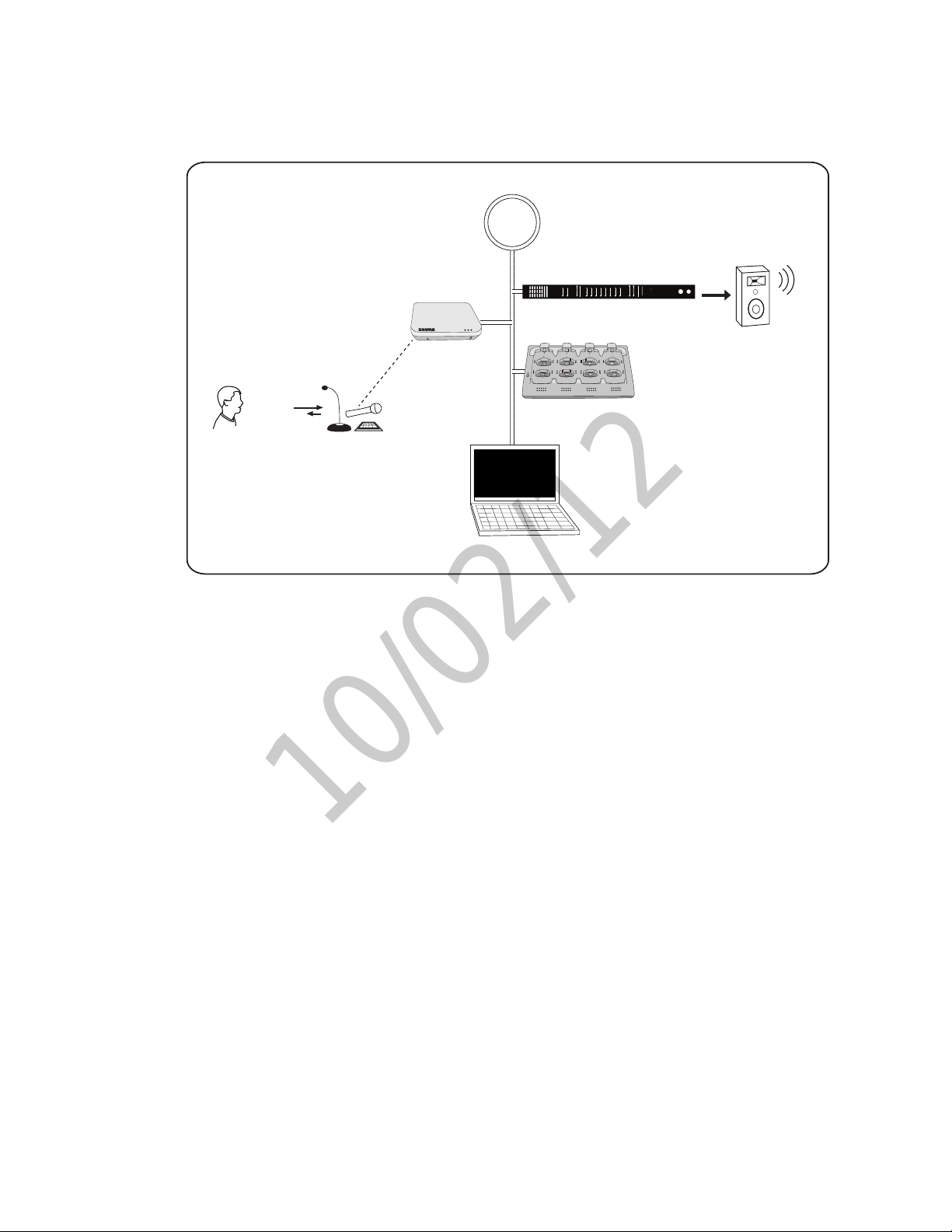
The following is an overview of each component and its function in the MXW system:
Network
INPUT: SPL
OUTPUT: Headphone
① MXW Microphones
•Convert audio into a digital RF signal that
transmits wirelessly to the APT.
•Available in a variety of form factors to
accommodate any event.
•Boundary and gooseneck models feature a
headphone jack for monitoring audio from the
network.
② Access Point Transceiver (APT)
•Transports encrypted, wireless audio between
the microphones and the Dante network.
•Maintains stable audio transmission through
advanced interference detection and
automatic frequency coordination.
•Requires only a single Cat5e cable for power
(via PoE), system time-sync management,
and the communication of networked audio
and control data.
•Hosts the web browser-based GUI for remote
system management.
③
A B 1 2 3 4 5 6 7 8
INPUT OUTPUT
sig/clip
②
mute
④
2
APT
①
1
5
6
NCS
⑤
GUI
the networking hub of an eight-channel MXW
system.
•Network Port 4 (Uplink) can be configured
to restrict audio and provide protected data
uplink to a corporate network.
•Input channels add audio to the network for
monitoring at the microphone headphone
output.
Note: The ANI can be substituted with the Shure
SCM820 Digital IntelliMix Mixer.
④ Networked Charging Station (NCS)
•Recharges microphone batteries by
connecting to the USB port of the microphone.
•Links up to eight microphones at a time to
channels in a group.
•Transmits detailed battery information to the
network.
•LEDs display microphone battery charge
status.
line
aux
sig/clip
mute
3
7
Audio Network Interface
0
power
-9
0
-18
ethernet
line
-6
-24
network audio
aux
-12
-30
HEADPHONE
-18
mic
-36
-24
lockout
-48
-60
push to solo | hold to mute adjust
ANI
4
8
⑤ Graphical User Interface (GUI)
The MXW System is managed from the
graphical user interface (GUI). The computer
must be networked to the APT to access the
GUI from a web browser. Use the software
interface for the following system functions:
•Assign components to groups to determine
the routing of digital audio and control data.
•Perform an RF spectrum scan to accurately
survey a site's spectrum activity over a
duration of time.
•Monitor microphone battery statistics during
the charge.
•Control microphone activity state, gain setting
and EQ filters.
•Customize the function of LED and mute/
active button of the microphone.
•Configure IP settings.
③ Audio Network Interface (ANI)
•Converts 24-bit/48k digital audio from the
network into analog direct outputs.
•Four-port gigabit switch enables the ANI to be
7
Page 13

System Setup
10/02/12
System Setup
8
Page 14
System Setup
++++++++ ++
www.shure.com
MXWANI8
M XW AN I8
uplink
Input: 100-240V ~ 1A max. 50/60 Hz
234
Class 0 Po E
1
++++++++ ++
www.shure.com
MXWANI8
M XW AN I8
uplink
Input: 100-240V ~ 1A max. 50/60 Hz
234
Class 0 Po E
1
uplin k
234
Class 0 Po E
1
②
①
7
8
6
5
1
2
3
4
④
③
Link
Power
10/02/12
Install and Power the Hardware
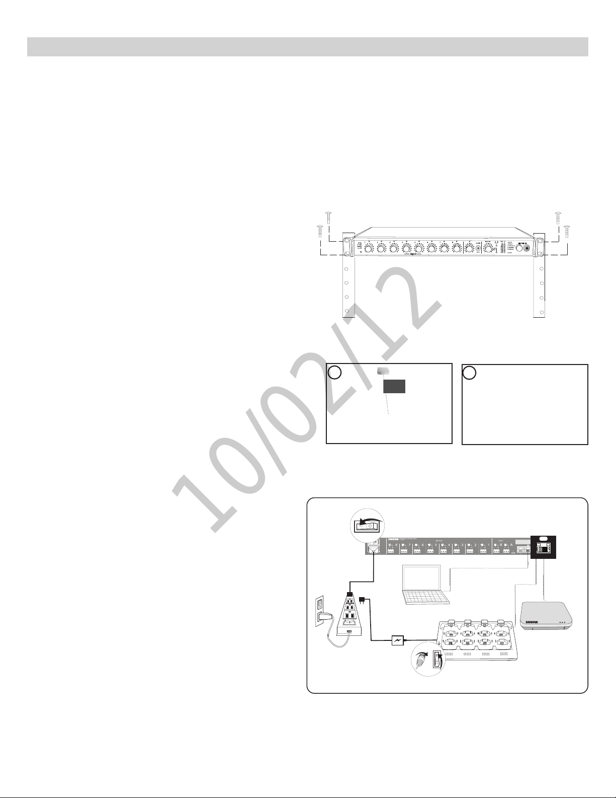
Additional Equipment Requirements
① Network Cables
Ensure all network cables are shielded Cat5e or higher and do not exceed 100 m between network devices.
② Audio Cables
Reference the guide supplied with the MXWANI Hardware Kit to assemble the output cables to the connectors and strain relief tabs.
③ Gigabit DHCP Router
DHCP routers provide the most reliable networking hub for the system.
Rackmount the ANI
Use the screws and washers supplied in the Hardware Kit to mount the ANI.
1 2 3 4 5 6 7 8
gain
w cut
o
l
hi shelf
er
t
me
push to solo | hold to mute
A
L+R SUM
Mount the APT
① Position the Access Point
The access point contains multiple directional antennas to provide
steady, reliable wireless communication. The cardioid radiation pattern
is strongest from the top of the face plate.
Use the following guidelines when mounting the access point:
•Direct the antenna toward the intended coverage area.
•Position access point so there is nothing obstructing a line of sight to
the microphones.
•Keep antennas away from large metal objects.
•Mount access points at least four feet apart.
1
2
LIM
MASTER
A
B
er
w
o
p
A
B
UX IN
HEADPHONE
0
net
r
ethe
9
k audio
r
o
w
t
ne
-1
8
omix link
t
au
-2
4
gain
er
x
dual mi
-3
6
limi
t
er
-4
8
-6
0
lockout
Important: Always perform a "walk around" test to verify coverage before
using a wireless system during a speech or performance. Experiment
with antenna placement to find the optimum location. If necessary, mark
"trouble spots" and ask presenters or performers to avoid those areas.
② Mount the Unit
Secure the unit to a ceiling or wall using the supplied mounting screws.
Power the Hardware
① ANI
Connect the IEC power cable from the back panel to an AC power
source. Turn on the power switch.
② APT
The APT requires PoE to operate. Use a Cat5e cable to connect the
APT to the ANI port 1 or to a gigabit switch with PoE. There is no power
switch.
③ Charger
Connect the PS45 external power supply from the charger to an AC
power source. Turn on the power switch.
④ Gigabit Ethernet Router or Switch
Connect the router or switch to an AC power source. Turn on the power
switch.
①
1
Class 0 Po E
③
1
②
15V 0.6A
power
2
5
6
4
3
7
8
9
Page 15
System Setup
++++++++ ++
www.shure.com
MXWANI8
M XW AN I8
uplink
Input: 100-240V ~ 1A max. 50/60 Hz
234
Class 0 Po E
1
10/02/12
Connect the Components to Form a Network
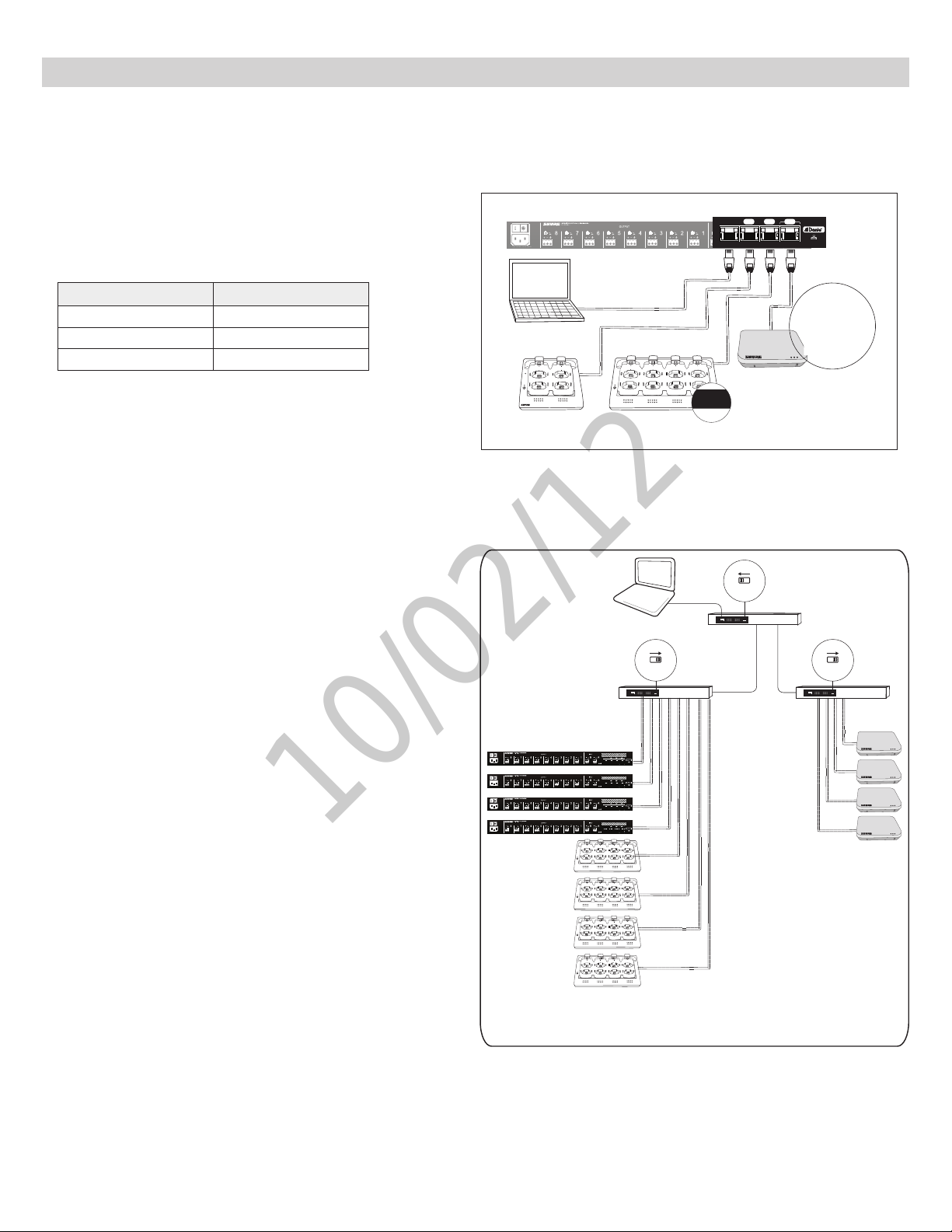
The following are two setup examples for the MXW system. See Networking section for more details on Dante digital audio and networking best practices.
Single Group System (Automatic
234
Configuration)
Use a Cat5e cable to connect the charger and APT to one of four ports of
the ANI network interface. Reference the table for connecting to the ports:
uplin k
1
Class 0 Po E
Port To Component
① Port 1 (PoE) APT
② Port 2 Charger
④ Port 4 (Uplink) Computer (optional)
Requirements:
•
Cat5e(orhigher)ShieldedEthernetCables(≤100m)
Multiple Group System
Follow these steps for connecting a multiple-group system:
1. Connect a DHCP enabled router to a computer.
2. Connect each charger and audio output device to the router with network
cables
3. Connect each access point to the network via a PoE source.
Requirements:
•
Cat5e(orhigher)ShieldedEthernetCables(≤100m)
• Gigabit Ethernet switch (DHCP-enabled router recommended)
• Computer
Power
Link
www.shure.com
MXWANI8
M XW AN I8
++++++++ ++
Input: 100-240V ~ 1A max. 50/60 Hz
www.shure.com
MXWANI8
M XW AN I8
++++++++ ++
Input: 100-240V ~ 1A max. 50/60 Hz
www.shure.com
MXWANI8
M XW AN I8
++++++++ ++
Input: 100-240V ~ 1A max. 50/60 Hz
www.shure.com
MXWANI8
M XW AN I8
++++++++ ++
Input: 100-240V ~ 1A max. 50/60 Hz
④
③
1
2
5
6
Single-Group System
ON
DHCP
234
1
uplink
Class 0 PoE
234
1
uplink
Class 0 PoE
234
1
uplink
Class 0 PoE
234
1
uplink
Class 0 PoE
4
2
1
3
5
7
6
8
4
2
1
3
5
7
6
8
4
2
1
3
5
7
6
8
4
2
1
3
5
7
6
8
①
②
4
3
7
8
ON
OFF
DHCP
OFF
ON
OFF
DHCP
PoE
10
Four-Group System
Page 16
System Setup
mxwani-aa1.local
192-168-200-22
mxwapt8-ffe761.local
192-168-200-23
10/02/12
Access the MXW System Interface
The MXW System is controlled and monitored on a graphical user interface (GUI) that opens in a web browser. The computer must be networked to the APT
to access the GUI.
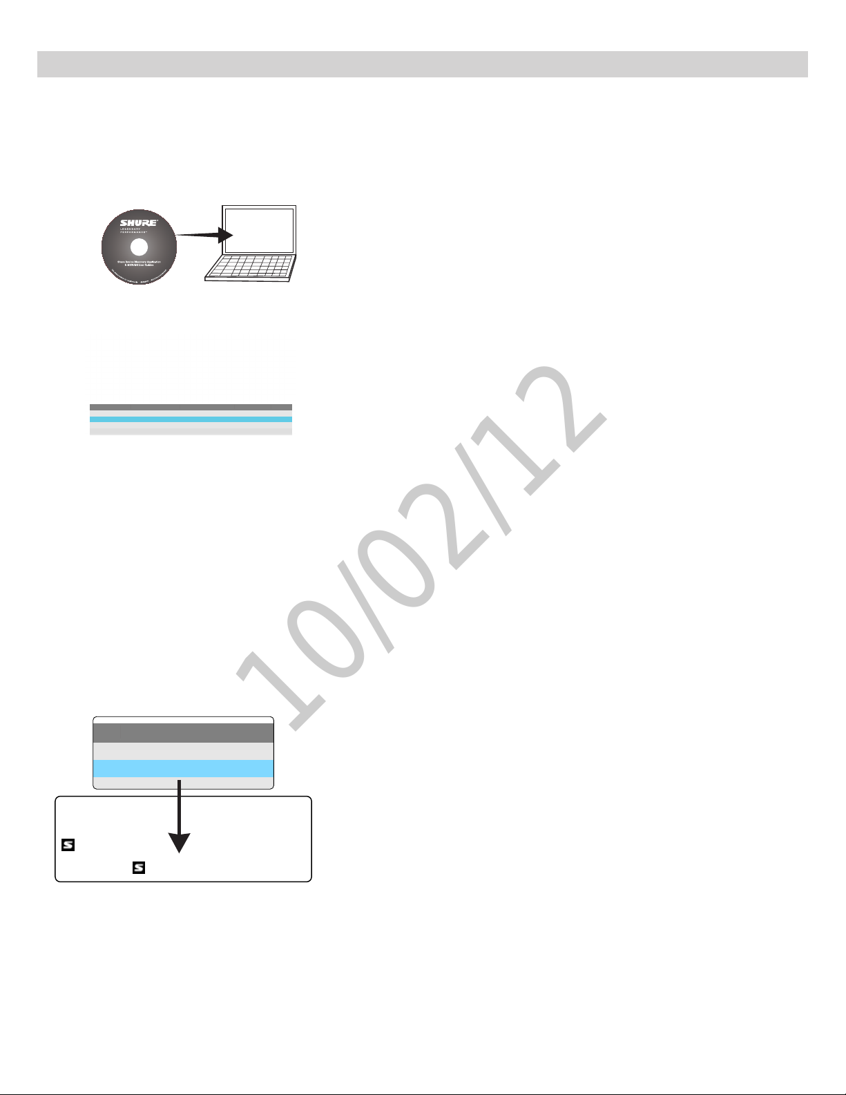
1. Load and install the Discovery Application.
This automatically installs the required Bonjour device discovery tool to the computer.
2. Launch the application.
The app displays all Shure devices on the network.
NameModel DNS name IP Address Dante
ANI1
MXWANI8
MXWAPT8
Conference1
mxwani-aa1.local
mxwapt8-ffe761.local
192-168-200-22
192-168-200-23
yes
yes
3. Select and open the APT.
The MXW System Interface opens in a web browser.
4. Bookmark the device's DNS name.
The DNS name is used to access the interface without the Discovery App.
11
Page 17

System Setup
10/02/12
Assign Components to a Group
Components must be assigned to a group to form the communication link of audio and control data. On the Configuration tab, select the following components
to form a group of up to 8 channels:
1. Select an APT for Group 1
The pop-up menu will display all APTs on the network. This determines
if the group has four or eight channels (APT4 or APT8).
2. Select the charger(s).
When using gooseneck microphones, it is necessary to use two chargers
for 8 microphones. (Gooseneck microphones take up front and back
slots.)
3. Select the Audio Output Device(s).
This can be an ANI4, ANI8 or SCM820 IntelliMix® Mixer.
id? Button flashes the LEDs of the selected device for
easy identification during setup.
12
Page 18
System Setup
7
8
6
5
1
2
3
4
link
7
8
6
5
1
2
3
4
1
2
3
4
10/02/12
Set Up Microphones
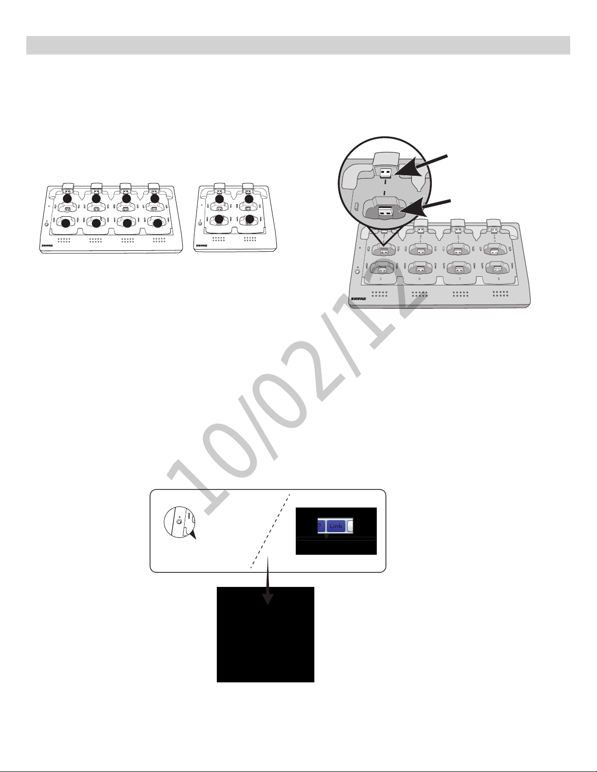
1. Arrange microphones in the charger.
Microphones are linked to channels according to the arrangement in the charger.
8-Channel Charger
1
1
Power
5
Link
5
(NCS8)
4-Channel Charger
2
2 3 4
6
6
7 8
4
3
7
8
Power
Link
1
3 4
Charger Slots Correspond to Channels
(NCS4)
2
Power
Link
For gooseneck mics
For bodypacks, handhelds
and boundary mics.
Connecting the Microphone to the Charger Slot
2. Link the microphones to channels.
The Link procedure can be done from two places:
•Charger: Press and hold the Link button for 6 seconds. The LEDs flash during the process and turn solid green once the link is successful.
•GUI: From the Configuration page, press the Link button in the group row.
13
Page 19
System Setup
++++++++ ++
www.shure.com
MXWANI8
M XW AN I8
uplin k
234
Class 0 Po E
1
uplin k
234
Class 0 Po E
1
uplin k
Class 0 Po E
Class 0 Po E
1
②
②
③
①
7
8
6
5
1
2
3
4
7
8
6
5
1
2
3
4
15V 0.6A
power
10/02/12
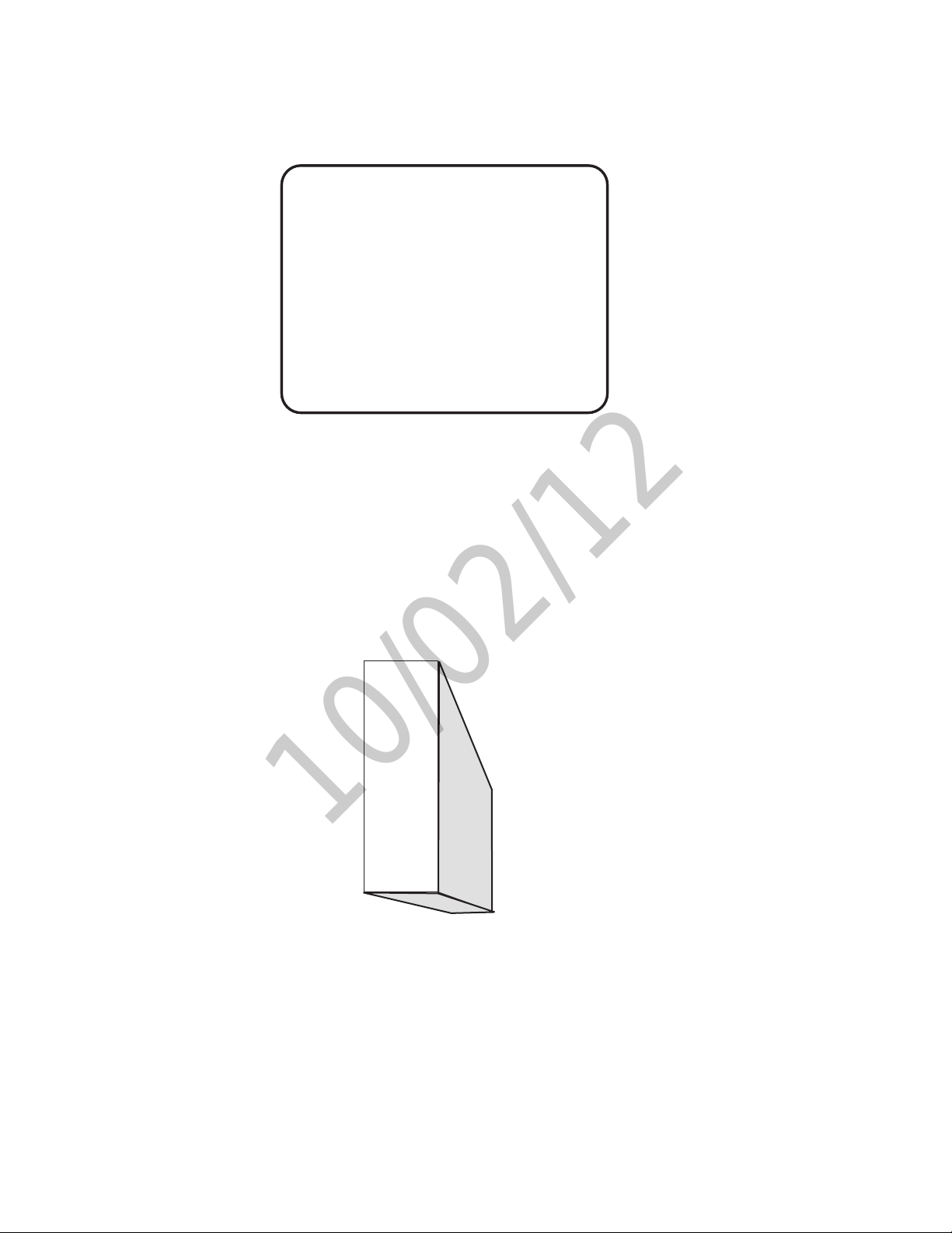
3. Remove mics from the charger.
The microphone status LEDs will flash, and will remain steady once the audio is ready.
4. Set mic gain
Mic gain is adjusted on the Monitor tab of the GUI.
Signal
indicator
Gain
14
adjustment
Monitor Tab
Page 20
System Setup
10/02/12
Microphone Placement
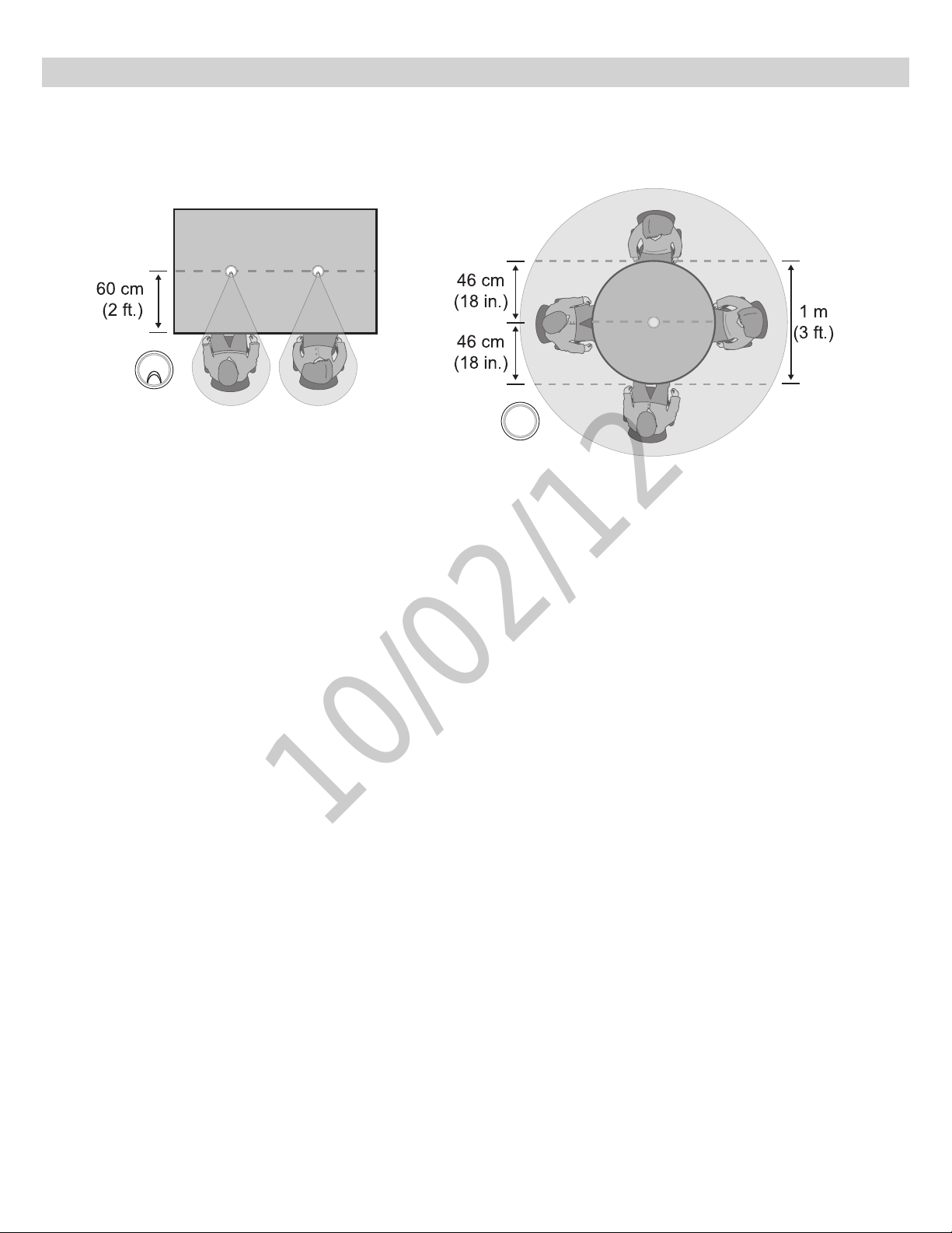
For best low-frequency response and rejection of background noise, place the microphone on a large, flat surface, such as a floor, table, or lectern.
To reduce reverberance, avoid reflective surfaces above or to the side of the microphone, such as beveled sides of pulpits or overhanging shelves.
15
Page 21

Hardware Interface Description
10/02/12
Hardware Interface Description
16
Page 22
Hardware Interface Description
10/02/12
Access Point Transceiver (APT)
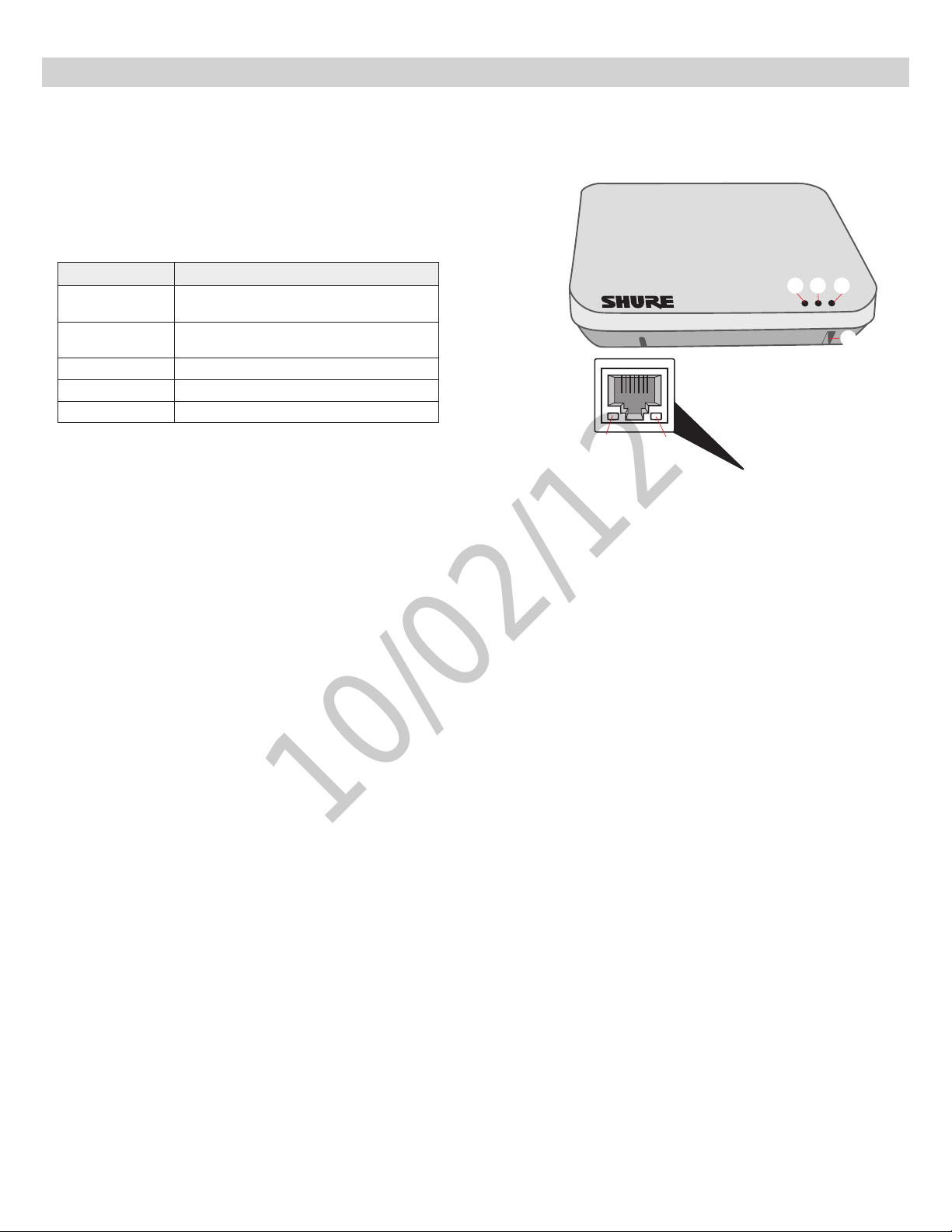
① Power LED
Illuminates green when Power over Ethernet (PoE) is provided.
② Network Audio LED
•Solid Green: Sending or receiving a digital audio signal.
•Flashing Green: Cannot establish a connection.
③ RF Link LED
Color Status
Green
Solid Yellow
Flashing Yellow The ID button in the GUI has been pressed.
Solid Red Problem with RF connection ???
Flashing Red No microphones are linked to the unit.
≥1linkedmicrophoneispoweredoninthe
Active or Mute state.
≥1linkedmicrophoneisintheStandbyorOff
state.
①
②
⑧
③
④
④ Reset Button
Press and hold the reset button for 10 seconds to hard reset the MXW
system to factory default settings.
Note: Performing a reset will delete system configurations made in the
GUI, including device association and microphone link.
⑤ Ethernet Jack
Connects a Cat5e (or higher) cable to a PoE source and the network.
⑥ Network Status LED (Green)
Off = no network link
On = network link established
Flashing = network link active
⑦ Network Speed LED (Amber)
Off = 10/100 Mbps
On = 1 Gbps
⑧ Cable Routing Path
Routes the Ethernet cable to enable a flush-mount to the surface.
⑥
⑦
⑤
17
Page 23
Hardware Interface Description
10/02/12
Audio Network Interface (ANI)
①
④ ④⑤ ⑤
A B 1 2 3 4 5 6 7 8
INPUT OUTPUT
sig/clip
mute
③
line
aux
sig/clip
mute
⑥⑥⑦ ⑧ ⑨
③
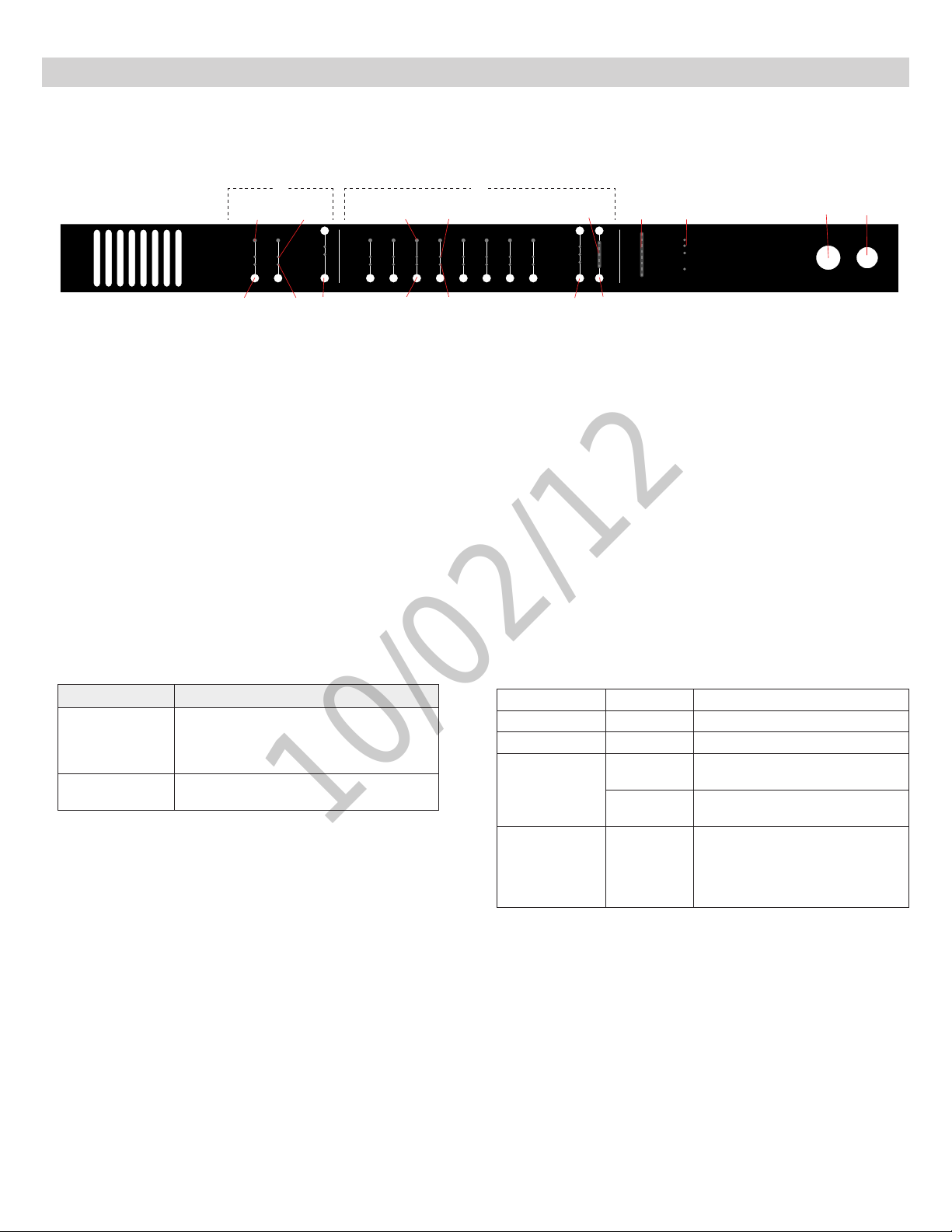
Front Panel
① Input Channels
Adds analog line- or aux-level signals to the digital network. When
associated to the APT, inputs are automatically routed to linked
microphone channels (Input A to channels 1-4; Input B to 5-8). Typical
applications include sending translated audio or a mix for personal
monitoring at the microphone headphone jack.
② Output Channels
Sends analog audio out from the digital audio network. When connected
to the MXW system, the outputs are automatically routed from the
associated MXWAPT.
③ Channel Select Button
Selects a channel and performs the following functions:
Action Function
•Listen to the channel at the headphone jack
Single Press
Press and Hold (3
seconds)
④ Selected Channel LED
Illuminates when a channel is selected.
⑤ Signal Strength LED (sig/clip)
Indicates audio signal strength for each channel:
Green = Normal
Amber = Strong
Red = Clipping (to eliminate clipping, attenuate the signal level at the
audio source)
⑥ Mute LED
Illuminates red when the Channel Select button is held for 3 seconds,
muting the channel. A muted channel is still routed to the HEADPHONE
jack for monitoring or troubleshooting.
⑦ Input Level Select Buttons
Set the selected channel to line- or aux-level to match the input signal.
⑧ Output Level Select Buttons
Set the selected channel to an output level that matches the connecting
device:
line: +4 dBU
aux: −10dBV
mic: −30dBV
•Display and adjust channel gain
Monitoroutputsignallevelonthe⑪Level
•
Meter
Mute/unmute a channel. Mute is indicated by
the⑥MuteLED.
②
⑩ ⑪ ⑫
0
line
-6
aux
-12
-18
mic
-24
push to solo | hold to mute adjust
⑨ Output Gain Control
Use the up/down buttons to adjust the channel gain attenuation from 0
dB (no attenuation) to -24 dB.
⑩ Output Gain Setting
Displays the attenuation made from the Output Gain Control.
⑪ Level Meter
Displays a selected channel’s audio level in dBFS. It is good practice to
use -18 dBFS on the output meter as an approximation of 0 VU on an
analog meter.
⑫ Hardware Status LEDs
Illuminate to indicate the status of the hardware:
LED Color Status
power Green Unit is powered on.
Ethernet Green Connected to an Ethernet device.
network audio
lockout Red
⑬ Headphone Volume Knob
Adjusts the volume to the headphone output.
⑭ Headphone Output
1/4” (6.35 mm) output jack for monitoring a selected channel.
0
-9
-18
-24
-30
-36
-48
-60
Green
Flashing
Green
⑬ ⑭
power
ethernet
network audio
lockout
HEADPHONE
Sending or receiving a digital audio
signal.
Cannot establish a connection.
Front panel gain and mute controls
are locked. The LED will blink when
a button is pressed while the hardware is locked. A channel can still be
selected for headphone monitoring.
Audio Network Interface
18
Page 24
Hardware Interface Description
10/02/12
Back Panel
②
MXWANI8
Input: 100-240V ~ TBD A max. 50/60 Hz
①
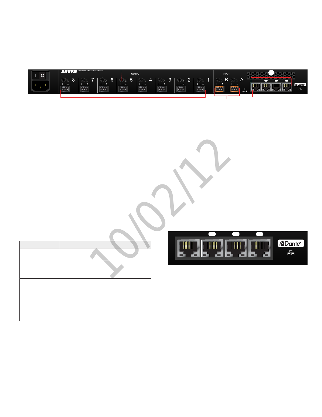
① AC Power
IEC connector 100 - 240 V AC.
② Power Switch
Powers the unit on or off.
③ Output Block Connectors (1-8)
Three-pin, low-voltage connector provides a direct output for each
channel.
④ Chassis Ground
Use to directly ground the cable shield to the chassis.
⑤ Input Block Connectors (A,B)
Three-pin, low-voltage connector adds line- or aux-level analog signals
to the digital network.
④
③
⑨
1234
Class 0 PoEuplink
⑤ ⑥
⑥ Reset Button
Press and hold the button for five seconds to reboot the device with
factory default settings.
⑦ Network Status LED (Green)
Off = no network link
On = network link established
Flashing = network link active
⑧ Network Speed LED (Amber)
Off = 10/100 Mbps
On = 1 Gbps
⑨ Network Interface
Digital Audio connection and networking capabilities with shielded Cat5e (or higher) cable.
⑦⑧
4-Port Network Interface
Port Description
Port 1 (PoE)
Ports 2 and 3
Port 4 (Uplink)
Provides Power over Ethernet (PoE) for the
Shure MXWAPT Access Point.
Connects to an additional ANI for clock synchronization, to an MXW charger, or to a control system.
By default, this port functions the same as
ports 2 and 3. However, it can be configured to
provide password protected uplink to corporate
LAN without network audio traffic. When Port 4
Uplink is enabled from the GUI, it only provides
access to the GUI, blocking data to the Shure
Discovery Application, Dante Controller and
Dante Virtual Soundcard.
1234
Class 0 PoEuplink
19
Page 25
Hardware Interface Description
10/02/12
Networked Charger (NCS)
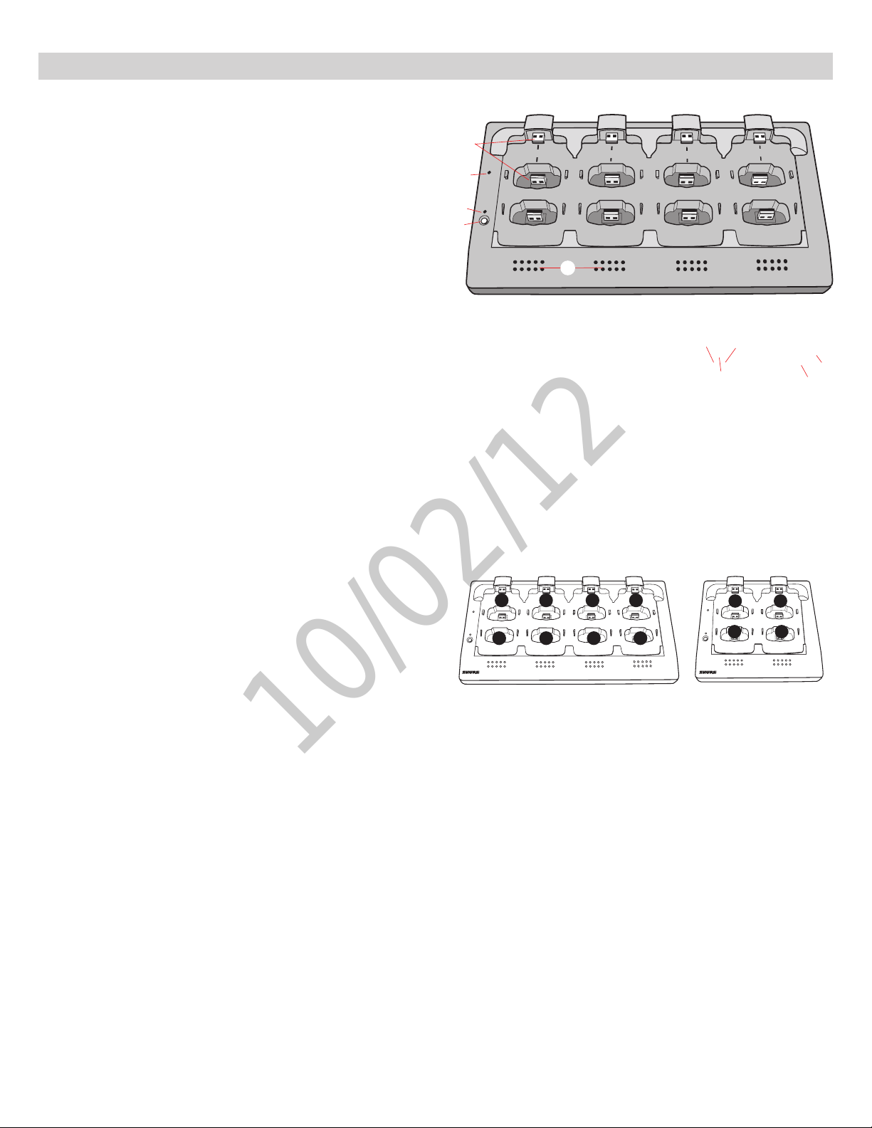
① Charging Slots (USB 2.0 Type A Plug)
Store, recharge and link microphones in the USB slots. Slots are
associated to channels in an APT according to the system setup in the
GUI.
② Power LED
Illuminates when the unit powered on.
③ Link LED
Illuminates after a successful link.
④ Link Button
Press and hold for 10 seconds to link all microphones in the charger to
channels of the associated APT.
⑤ Battery Status LEDs
Monitor microphone battery status during a charge, in increments of 10,
25, 50, 75, 100%
⑥ Locking DC Power Supply Jack
Screw the PS45 power supply to the input, illuminating the POWER LED.
⑦ Power Switch
Powers the unit on or off
⑧ Ethernet Port
Connects to the MXW system using a Cat5e (or higher) cable.
⑨ Network Status LED (Green)
•Off = no network link.
•On = sending or receiving digital audio over the network.
•Flashing = cannot establish a connection.
①
②
1
Power
2
③
④
Link
5
6
⑤
⑩ Network Speed LED (Amber)
•Off = 10 Mbps
•On = 100 Mbps
3
7
⑩
⑧
4
8
⑨
⑥
⑦
Charger Slots Correspond to Audio Channels
1
1
Power
5
Link
5
2
2 3 4
6
6
8-Channel Charger (NCS8) 4-Channel Charger (NCS4)
3
7 8
4
7
8
Power
Link
1
3 4
2
20
Page 26
Hardware Interface Description
10/02/12
Microphones
Description
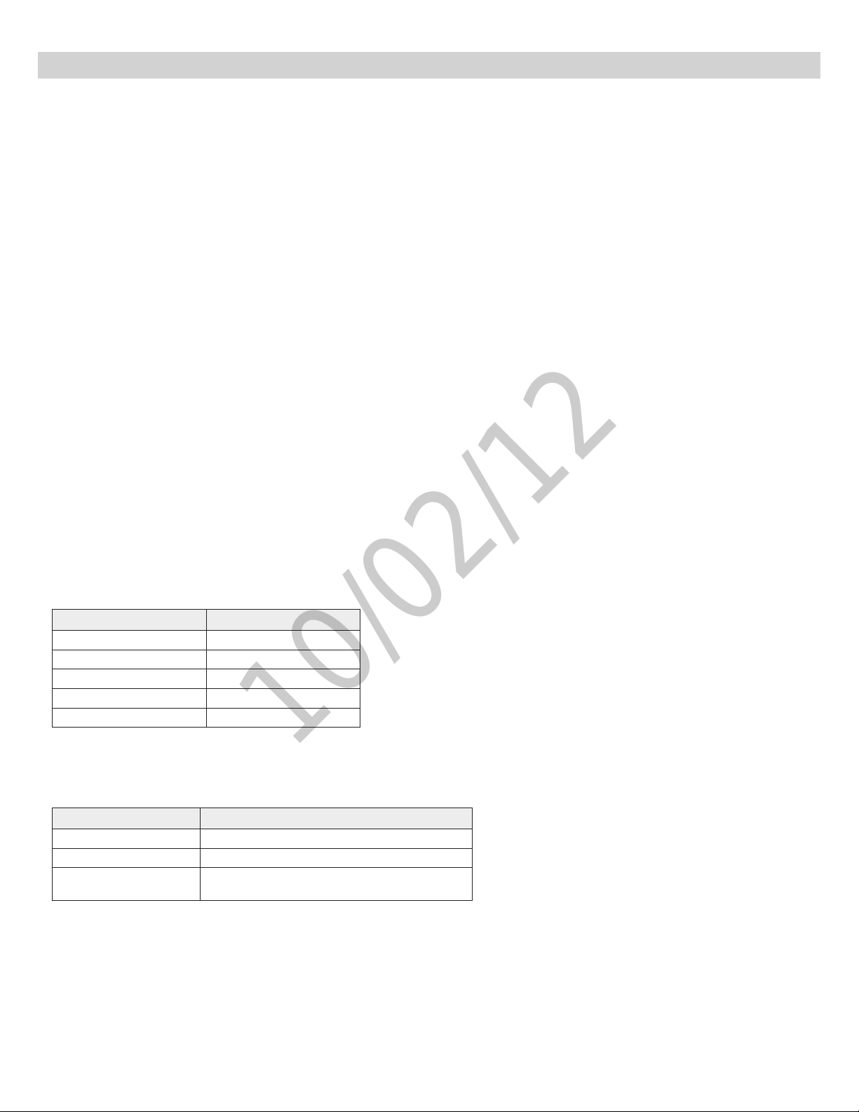
① Power Button
Press button to turn the microphone on; the microphone LED will flash green and red until turning a solid
color (color depends on state specified in GUI). Press and hold for 3 seconds to power off.
Note: The bodypack does not have a dedicated power button.
② Mute/Active Button
Changes the microphone state to Active or Mute. Each microphone type can be set to toggle or push-andhold from the Preferences tab of the GUI. The following describes the function of each setting:
•Toggle:Press and release the button to change the status to Active or Mute.
•Push-to-talk:Hold button to pass audio.
•Push-to-mute:Hold button to mute the audio.
③ Microphone State LED
Indicates the microphone state. Pulsing Red = Standby mode; Off = microphone is off.
Customize the indication of Active and Mute for each transmitter type from the Preferences tab of the GUI.
These options are displayed in the following table:
Mute Active
Solid Red Solid Green
Flashing Red Solid Red
Solid Red Off
Off Solid Red
Flashing Green Solid Green
Standby mode is always represented with a pulsing red LED.
④ Low Battery LED (Gooseneck and Boundary only)
Gooseneck and boundary microphones only.
Color Status
Off >10% battery runtime remains
Solid Red
Flashing Red
≤10%batteryruntimeremains
Battery is too low to transmit an RF signal.
Recharge the microphone.
⑤ Earphone Jack
1/8" (3.5 mm) jack for monitoring the return channel signal, such as translated audio.
⑥ Charge Connector (USB 2.0 Type A Jack)
Connects to the NCS charger slot or to the optional (?? model) USB adapter cable.
21
Page 27
Hardware Interface Description
10/02/12
Microphone Types and Applications
Choosing a Microphone Type
For each event, select microphones that will best serve the arrangement of participants and presenters.
The following is a chart of each microphone and its primary use:
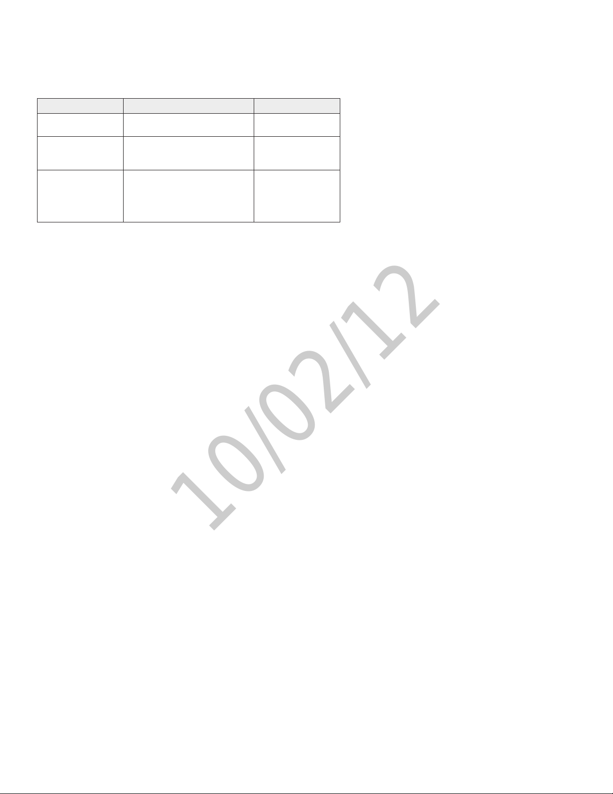
Type Use Placement Notes
Gooseneck
Boundary
Bodypack
Sits on a desk or podium with an
extended neck for close talking
Sits flat on a table or desk to
provide coverage for one or two
people.
Connects to a lavelier microphone
for placement on a speaker's
clothing. When no lavalier is connected, an internal omnidirectional
microphone is activated.
Microphone States
After a microphone has been linked to the network, it is in one of four states (or, levels of activity). The following is a summary of each state:
Active
Ready to pass audio to network.
Mute
Audio is muted.
Standby
Audio is muted and the microphone is in a hibernation state to conserve the battery.
Off
No connection to the network. The microphone must be turned on using the power button on the mic.
Initial States After Removing from Charger
Each microphone type can be assigned to a specified state whenever it is removed from the charger. Go to
the Preferences tab of the GUI to set the initial state for each microphone type.
When the Initial State is set to Standby, pressing the microphone's mute button will return it to one of two
states as defined in the Switch behavior:
• Push-to-talk
• Active toggle
For example, an installer may prefer to have the handheld microphones exit the charger with a Mute status to
avoid transmitting any handling noise to the audience.
22
Page 28
Hardware Interface Description
7
8
6
5
10/02/12
Rechargeable Microphone Batteries
MXW microphones feature the Shure rechargeable Lithium-ion battery. Lithium-Ion chemistry and intelligent Shure battery circuitry results in a rechargeable
battery with no memory effect. It can be recharged at any time; a complete discharge is not necessary.
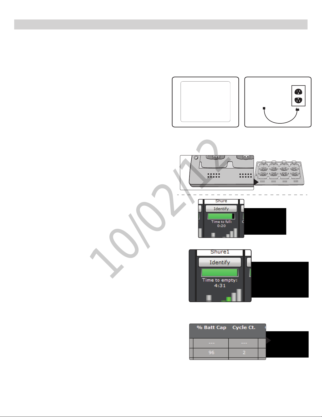
Recharging the Battery
There are two ways to recharge the microphone battery:
Using the NCS Charger
Use the charger slots to recharge and store the microphones. Handheld,
bodypacks, and boundary microphones use the vertical slots; gooseneck microphones use the back horizontal slots.
?? Model USB Power Adapter
The USB adapter allows the microphone to charge during operation.
Monitoring the Battery Information
Charge to Full Indicators
When the microphone is charging in the NCS charging station, the charger
LEDs display battery in increments of 10, 25, 50, 75, 100%
For further detail, the Monitor page displays the time to full charge in
hours:minutes.
Battery Runtime Remaining
When the microphone is out of the charger, the Monitor tab will display the
runtime remaining in hours:minutes.
Battery Life Statistics
On the Utility tab of the GUI, two battery life statistics that are displayed:
•% Battery Capacity: Percentage of charge capacity compared to a new
battery
•Cycle Count: Number of charge cycles logged by the battery.
2
1
6
5
4
3
7
8
Replacing the Battery
Caution! Danger of exploding if battery is incorrectly replaced. Use only with the
same or equivalent type.
Use the following guidelines for replacing the battery:
1. Unscrew and open the battery door.
2. Disconnect the battery from the microphone. Properly dispose of the old
battery.
3. Plug the new battery to the jack on the microphone.
4. Replace the battery door and screw it shut.
23
Page 29

Networking
10/02/12
Dante technology uses standard IP over Ethernet and safely coexists on the same network as IT and control
Networking
data. It provides an integrated solution to transport two types of data over the same network cable: Shure
Control, and Dante Audio and Controller.
Shure Control: GUI and 3rd Party Control
The Shure Control carries data for the GUI operation, firmware updates and 3rd party control systems
(AMX, Crestron, Extron). This data is transmitted over all MXW components connected to the network.
Dante Audio and Controller
This network carries both the Dante digital audio and the control data for Dante Controller. This data is
transmitted between the APT and the ANI.
24
Page 30

Networking
10/02/12
Networking Best Practices
Use the following best practices when setting up a network to ensure reliable
communication:
• Always use a "star" network topology
• Use only 1 DHCP enabled server per network. Disable DHCP addressing
on additional servers
• When using an AXT620 Ethernet Switch, turn on the switch first before
turning on additional components connected to the network
• To expand the network, use multiple Ethernet switches in a star topology
• Connect each device directly to the port of an Ethernet switch. Avoid "daisy-
chaining" Ethernet port connections between devices for larger networks.
• Do not loop network connections
• All networked devices must be set to the same subnet mask
• All devices must be at the same firmware revision level, with the exception
of the AXT620 Ethernet Switch
Network Topologies
There are several ways to configure a network of devices. In general, you should always use a "star" network topology where each device uses one connection
to an Ethernet switch port. If multiple switches are used, each switch is individually connected to one connection to the next level of Ethernet switch.
Below are three example configurations of large networks of devices.
Multiple Ethernet Switch Setup #1
• Any AXT620 switch (but only one) can be set as the DHCP server
• Each networked device needs an individual connection to the switch
• Connect them via any port
Server
Client
Client
AXT620 with front panel DHCP switch set to
OFF
AXT620 with front panel DHCP switch set to
OFF
AXT610 ShowLink Access Point
AXT620 with front panel
25
DHCP switch set to ON
Page 31

Networking
10/02/12
Multiple Ethernet Switch Setup #2
Each networked device needs an individual connection to the switch.
AXT620 with front panel
DHCP switch set to
ON
Server
Client
Multiple Ethernet Switch (Wi-Fi) Setup #3
Each networked device needs an individual connection to the switch.
Wi-Fi Router (DHCP enabled)
Ethernet Switch
AXT610 ShowLink Access Point
AXT620 with front panel
DHCP switch set to OFF
Server
Client
Client
AXT620 with front panel DHCP switch set to OFF
AXT610 ShowLink Access Point
26
Page 32

Networking
10/02/12
Configuring Firewalls for Mac or Windows Operating Systems
Mac OS Native Firewall
1. Open System Preferences.
2. Select Security, and then select the Firewall tab.
3. To enable editing, make sure the lock icon at the bottom of the window is
unlocked before entering your password.
4. If the firewall is on, select Advanced. For each of the following applications,
select "Allow Incoming Connections":
• Wireless Workbench 6.app
• slpd
• snetDameon
• acnproxy
Windows XP or Vista Firewall
1. From the Start menu, select Control Panel.
2. Select Windows Firewall.
3. In the Windows Firewall window, if the firewall is set to On, select the
Exceptions tab and add the following applications to the exceptions list:
• WWB6.exe
• SLPD.exe
• SNETDAMEON.exe
Windows 7 Firewall
1. From the Start menu, select Control Panel.
2. Select Systems and Security.
3. Select Windows Firewall.
4. Select Allow a program or feature through Windows Firewall.
5. To view the list of applications, select Change Settings.
6. Select the following applications to allow them:
• WWB6.exe
• SLPD.exe
• SNETDAMEON.exe
Configuring Wi-Fi for Wireless Networking
When using Wireless Workbench over Wi-Fi, it’s important to set up the wireless router properly for best performance. Wireless Workbench employs ‘multicast’
data protocols to communicate to the Axient and PSM1000 devices. Wi-Fi treats broadcast and multicast packets differently than general packets for backward
compatibility reasons. In some cases, the Wi-Fi router will limit the multicast packet transmission rate to a value that is too slow for Wireless Workbench to
properly operate.
By default, most Wi-Fi routers are configured to operate in ‘b/g-mode’, which tells the router to allow both 802.11g and older 802.11b devices to operate over
the network. In this configuration, some routers will automatically limit the multicast data rates (or sometimes referred to as ‘basic rate’, or ‘management rate’) to
1-2Mbps. For small wireless microphone configurations of less than 20-30 channels, this Wi-Fi setting should not cause any problems with Wireless Workbench.
Tip: For larger wireless microphone configurations of greater than 30 channels, it’s recommended to configure the Wi-Fi router to operate in ‘g-mode’
only. Most routers will increase the multicast transmission rate to 6Mbps when operating in ‘g-mode’ thereby providing adequate bandwidth to Wireless
Workbench.
Important: For best performance, use a Wi-Fi router that does not limit the multicast rate to 1-2 Mbps.
Shure recommends the following Wi-Fi router brands:
• Cisco
• Linksys
• Apple
27
Page 33

Networking
10/02/12
Troubleshooting
Factory Reset
If a device isn't appearing on the network, perform a hard reset to return the device to default settings. Factory default settings are designed for automatic compatibility with other Shure networked devices.
Use following instructions to reset each device:
Access Point Transceiver
Press and hold the reset button for 10 seconds. The network audio status LED will briefly turn off to indicate the unit is rebooting.
Note: Factory resets delete system configurations made in the GUI, including device association and microphone linking.
Audio Network Interface
Press and hold the reset button for 5 seconds. The front panel LEDS will flash to indicate the unit is rebooting.
Networked Charging Station
Press and hold the link button while powering up the charger. Continue to hold the link button for 10 seconds. The LEDs will flash to indicate the unit is
rebooting.
Set Appropriate Latency Settings
Latency settings determine the amount of time that a device can spend processing data packets. When a receiver is overloaded with traffic, audible clicks and
pops may occur. Increasing the latency setting will improve performance for large networks.
Number of
Switch Hops*
* Each device is represents one switch hop.
Recommended
Latency Setting
Dedicate a Device for Master Clock
Dante uses the IEEE 1588 Precision Time Protocol (PTP) to automatically determine a single access point to act as the master clock for the network. This is
typically the first APT that connects to the network (if several connect simultaneously, the master defaults to the APT with the lowest MAC address). The remaining Dante audio components slave to the master
When a master device shuts down or goes offline, the system will automatically begin selecting another master. During this selection time (up to xx seconds),
the entire system will NOT pass audio.
If the network or building management requires that devices are periodically shut down, you can manually select an access point as the Preferred Master device
from Dante Controller software. This allows the installer to set up the system to ensure that the master access point never shuts down during events.
28
Page 34

Software Introduction
10/02/12
MXW hardware networks to a computer to operate with several software programs, augmenting the system with additional features and comprehensive remote
Software Introduction
management.
The following software components are used with the MXW series:
• Shure Device Discovery Application: Uses Bonjour networking technology to display all Shure devices on the network that include a graphical user
interface (GUI).
• MXW Series GUI: Hosted from the APT webserver and accessed from a typical web browser, this GUI is used to manage the network of MXW components.
• MXWANI GUI: Hosted from the ANI webserver and accessed from a typical web browser, this GUI is used to monitor the ANI's analog inputs/outputs and
network configuration.
• Dante Controller: Dante Controller (DC) is a free software by Audinate that is used to configure and manage a network of Dante devices.
• Dante Virtual Soundcard: An audio driver used to monitor and record digital audio without additional equipment.
29
Page 35

Software Introduction
10/02/12
Shure Device Discovery Application
The Device Discovery application finds all Shure devices on the same network that have an embedded web server. These devices network with a computer to
access the The Discovery app is included on the CD-Rom supplied with the APT and can be downloaded from the Shure website.
Device Discovery with Bonjour: Bonjour software is bundled with the installation of the Shure Device Discovery application. Bonjour technology provides
zero configuration networking, allowing devices to automatically discover each other and configure to compatible settings.
Opening the MXW GUI
To access the MXW system GUI, follow these steps:
1. Load the Shure Device Discovery CD to a computer and install the application. Bonjour will install automatically to the computer.
2. Connect the PC to the same network as the APT.
3. Turn off the PC's WiFi to force the wired network interface.
4. Open the Discover app to view all Shure devices on the network.
5. Double-click on a unit to open its GUI in a browser.
Note: When Port 4 Uplink mode is enabled on the ANI, the Discovery app will not find the GUI. However, the GUI can still be opened by the bookmark or
manually typing in the DNS name into the browser.
Recommended: Bookmark the GUI
The Discovery app uses Bonjour technology to open a device's GUI using its DNS name (Domain Name System). The DNS name is unique for each device and
will never change (unlike IP addresses). Bookmark the GUI using the DNS name allows reliable access to the GUI without going through the Device Discovery
app.
30
Page 36
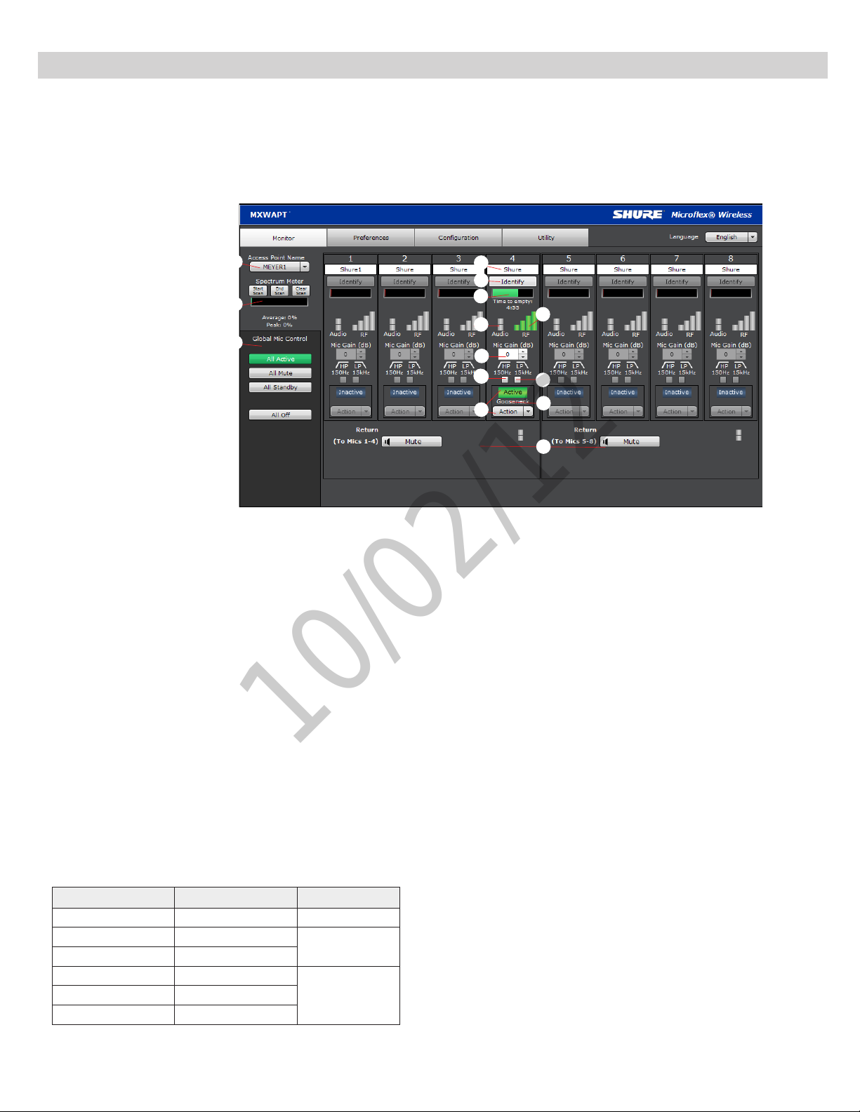
Software Introduction
10/02/12
MXW System Graphical User Interface (GUI)
A graphical user interface (GUI) is software that allows comprehensive system control and monitoring from a computer. It is hosted from an embedded server
built into the APT, and is accessible when properly networked to a computer or 3rd party control device. All hardware functions can be adjusted using the GUI.
GUI Description
The following is a description of each tab of the GUI:
①
②
③
Monitor T ab
① APT Selection
Selects an APT for monitoring channel and RF spectrum information.
② Spectrum Meter
Displays the RF spectrum availability from a scan from the APT. See
Spectrum Scan section for more details.
③ Global Mic Control
Controls the status of all microphones linked to the APT.
④ Microphone Name
Microphone names can be customized with up to 31 any characters in
length except '=','.' or '@'.
⑤ Identify Button
When clicked, this commands the microphone to beep and its LED to
flash. Microphones must be removed from the charger for this function.
⑥ Battery Status
While charging: Displays the remaining time until the microphone
battery is fully charged.
Not charging: Displays the remaining battery runtime of the microphone.
⑦ RF Signal Strength
⑧ Audio Input Meter
Indicate the average input signal level.
LED Audio Signal Level Description
Red (6) -0.1 dBFS Overload
Yellow (5) -6 dBFS
Yellow/ Green (4) -12 dBFS
Green (3) -20 dBFS
Green (1) -40 dBFS
Normal peaks
Signal PresentGreen (2) -30 dBFS
④
⑤
⑥
⑧
⑦
⑨
⑩
⑫
⑪
⑬
⑭
⑨ Mic Gain
Adjusts microphone gain from -25 dB to +15 dB gain in 1 dB steps.
⑩ High Pass Filter
Engages a 6 dB-per-octave filter below 150 Hz for attenuating undesired
low frequencies, sometimes caused by table vibrations or air-conditioning
rumble.
⑪ Low Pass Filter
Engages a 6 dB-per-octave filter above 15 kHz for attenuating undesired
high frequencies, sometimes caused by sibilant vocals or paper rustling.
⑫ Microphone State
Microphones are in one of four states:
•Active: Microphone is on and passing audio to the network.
•Mute: Microphone is on but the signal is muted.
•Standby: Conserves battery charge and allows the GUI to change the
state to Active or Mute.
•Off (Inactive): The microphone is powered off. A microphone in this
state cannot be controlled by the GUI (it can only be turned on using
the power button on the mic).
⑬ Microphone Type
Displays the microphone type:
•Gooseneck
•Bodypack
•Boundary
•Handheld
⑭ Return Channels
Monitor the signal level and mute/unmute the audio of the return channel.
31
Page 37

Software Introduction
10/02/12
Preferences T ab
① Switch Behavior
Customize the switch for each microphone type.
•Toggle: Press and release the button to change the status to Active
or Mute.
•Push-to-talk: Hold button to pass audio.
•Push-to-mute: Hold button to mute the audio.
•Disabled: The button does not affect the audio.
② Initial State from Charger
Assigns the initial state for each microphone type after removal from the
charger:
•Active: Microphone is on and passing audio to the network.
•Mute: Microphone is on but the signal is muted.
•Standby: Conserves battery charge and allows the GUI to change the
state to Active or Mute.
•Off (Inactive): The microphone is powered off. A microphone in this
state cannot be controlled by the GUI (it can only be turned on using
the power button on the mic).
③ LED Behavior
Set the behavior of the mute/active LED for each microphone type:
Mute Active
Solid
Red
Flashing
Red
Solid
Red
Off
Flashing
Green
Standby mode is always represented with a pulsing red LED.
④ Mute Preference
•Local Mute - Individual: Each microphone is muted individually.
•Local Mute - All: All microphones mute when any microphone is muted.
•External Mute: Microphones are muted by a 3rd-party control device.
⑤ RF Power Max
Determines the maximum distance that an APT will transmit.
•Low: ??'
•Medium: ??'
•Medium High: ??'
•High: ??'
⑥ Out of Range Alarm
⑦ Back in Range Action
⑧ Linking Preference
⑨ Language
⑩ Save/Load Preferences
⑪ Password Setup
⑫ Register the Product Link
Solid
Green
Solid
Red
Off
Solid
Red
Solid
Green
Conguration Tab
① Device List
Customize the switch for each microphone type.
② Device Name
Device names can be customized with up to 31 any characters in length
except '=','.' or '@'.
③ Network Interface Selection
Determines which network interface's IP settings are displayed.
•Control:
•Network Audio:
④ IP Mode
Sets IP mode of the selected network interface:
•Auto (DHCP): For automatic DHCP or Link-Local IP addresses.
•Manual (Static): For Static IP addresses.
⑤ IP Settings
Displays the IP Address, Subnet Mask, and Gateway for each network
interface.
⑥ MAC Address
The network interface's unique identification.
⑦ Group Row
Assign APTs, chargers, and audio output devices to form each group.
⑧ id? Button
Commands the selected device's LEDs to flash for easy identification.
⑨ Link Button
Links microphones to channels for the selected charger.
Utility T ab
① Export
Exports the data table to a text file that can be saved to a computer.
② Group
Indicates to which group the device is assigned/linked.
③ Device
The device type or microphone channel.
④ Type
The device model number.
⑤ Name
Displays name as defined in ______??
⑥ IP Address Control
Displays the IP Address of the control network interface (Shure GUI
control).
⑦ IP Address Network Audio
Displays the IP Address of the Network Audio network interface (Dante
audio and control).
⑧ S/N
Displays the device's serial number.
⑨ % Battery Capacity
Percentage of charge capacity compared to a new battery.
⑩ Cycle Count
Number of charge cycles logged by the battery.
⑪ Current Version
Displays the device's firmware version.
32
Page 38

Software Introduction
10/02/12
Control Bar
① Identify Button
This button sends a command to the hardware to flash front-panel LEDs
for easy identification.
② Log Off
Logs the user out of the GUI. This appears only when a password has
been set for Admin or Tech level.
③ Language Selection
Selects the language for the GUI. This setting will be saved to the
computer.
Inputs/Outputs Tab
Inputs (Return Channels)
① Channel Name
Channel name is customizable by clicking in the text box. Names can be
up to 12 characters long.
② Input Gain Setting (A, B)
Sets the analog input gain level.
③ Audio Meter
Displays input audio levels prior to the analog-to-digital converter.
④ Mute Button
Mutes or unmutes the channel's audio. The button illuminates red when
a channel is muted.
Outputs (1-8, or 1-4)
⑤ Channel Name
Channel name is customizable by clicking in the text box. Names can be
up to 12 characters long.
⑥ Output Gain
Sets the output gain level.
⑦ Audio Meter
Displays output audio levels prior to the digital-to-analog converter.
⑧ Attenuation
Output attenuation is adjustable in 1 dB increments.
⑨ Mute Button
Mutes or unmutes the channel's audio. The button illuminates red when
a channel is muted.
Various
⑩ Network Audio Status
•Green = Sending or receiving a digital audio signal.
•Flashing green = Cannot establish a connection.
•Normal: Enables automatic Dante channel routing with an APT.
•Standalone: Channels must be routed manually with Dante Controller
software.
⑦ Device Name
Device name is customizable by clicking in the text box. Names can
be up to 12 characters long (alphanumeric and a limited set of special
characters are allowed).
⑧ Addressing Mode
Auto: IP settings are Link-Local or automatically accepted from a DHCP
server.
Manual: IP settings (IP Address, Subnet Mask, and Gateway) are static
and are entered manually.
⑨ MAC Address
⑩ Port 4 Mode
Configures the Port 4 of the network interface:
•Switched (default): Full Ethernet support.
•Uplink: Only control data for the GUI is transported. Multicast traffic for
Dante and the Shure Device Discovery is restricted.
⑪ Front Panel Lockout
Disables the front panel controls on the hardware. Channels can still be
selected for monitoring at the headphone jack.
⑫ Password
By default, the GUI has no password or security levels. Setting a
password for the Admin will automatically generate a Guest-level logon.
An additional, Tech-level logon can be created. The following describes
the access rights of each logon type:
Admin: Full editing rights. The Admin can enable or disable a Tech-level
logon.
Tech: Rights are limited to the functions that are also editable from the
hardware: gain, mute, solo, and reset.
Guest: Monitoring only.
⑪ Notes
Save project notes here, such as installation dates or IP information.
Preferences Tab
① Language
Selects the language for the GUI when the ANI is in Standalone Network
Mode. In Normal mode, this is defined in the APT GUI.
② Device Serial Number
Displays the devices serial number.
③ Firmware Version
Displays the current firmware version of the device.
④ Reset Button
Reboots the device with factory default settings.
⑤ Register This Product Link
Click to register the device at shure.com to receive product and software
updates.
⑥ Networking Mode
33
Page 39

Software Introduction
10/02/12
Dante Software by Audinate
Audinate software provides additional function and control of the Dante digital audio network. Visit
Audinate's website for instructions for download and installation.
Dante Controller
Dante Controller (DC) is a free software by Audinate that is used to configure and manage a network
of Dante devices. Use it to route channels between Dante-enabled devices and to monitor the status of
the device, clock, and network.
Note: DC software is not required for routing audio within the MXW system. Use caution when using DC, as changing settings may interfere with MXW system functionality.
Dante Virtual Soundcard
Dante Virtual Soundcard (DVS) acts as an audio driver used to monitor and record digital audio without
additional equipment. DVS uses a computer's standard Ethernet ports to transmit and receive up to 64
channels from any Dante enabled device on the same network.
34
Page 40

Optimizing the System
10/02/12
Optimizing the System
35
Page 41

Optimizing the System
10/02/12
Site Survey: RF Spectrum Scan
The APT features a scanning tool to survey the RF spectrum prior to the installation. It should be conducted during typical hours of activity to identify the availability of the RF spectrum. The channel count limit will be determined by the availability of clear spectrum.
During a scan, the APT turns off all associated microphones in order to survey the spectrum of the room for interference from devices such as cordless phones,
walkie-talkies, or intercoms.
Performing a Scan
The following steps are used to perform the RF scan:
1. Connect the APT and computer to the same network.
2. Open the Monitor tab of the GUI and press the Start Scan button.
3. Run the scan for the entire time that an event may take place.
36
Page 42

Optimizing the System
10/02/12
Setting RF Gain for Installation
Dynamic RF Power Control
By default, the MXW system automatically adjusts the RF power level based
on the distance between an APT and the microphones. This prevents signal
dropout if a microphone is taken outside of the radius of the coverage of the
current RF level.
Note: Greater RF coverage uses more battery power and decreases the
battery runtime. Additionally it increases the required distance between
systems.
Manually Setting RF Power
You can limit the RF gain in order to maximize RF efficiency of a fixed space
and save microphone battery life.
There are three stages of RF gain in the APT for coverage over a range
of installation sizes: Level 3: 100' radius, Level 2: 50' radius, Level 1: 25'
radius. RF setting affects the microphone battery (higher level uses more
power, reducing battery runtime) and the system ability to reuse channels
in a space. Using a lower gain level decreases space the needed between
systems to avoid conflicting DECT frequency allotment.
RF Level and Coverage Area
Level 3: 100'
Level 2: 50'
Level 1: 25'
Adjacent Room Freq. Coordination
Average Battery Runtime per Power Level
The following table displays the average runtime of the transmitter for each
RF power level:
RF Power Level
Low ? hours
Medium ? hours
Medium High ? hours
High ? hours
Microphone
Runtime
37
Page 43

Optimizing the System
10/02/12
Removing/Exchanging a Component from the Group
To exchange a microphone, place the new microphone in the charger slot that corresponds to the desired channel. Press and hold the link button for 10 seconds
to link the microphone to the channel. The old microphone will no longer be a part of the system and no change will occur for the remaining channels.
Important: Always note the charger slot and channel when replacing microphones. The link will immediately override the existing microphone's audio and
RF connection to the system.
38
Page 44

Firmware Updates
10/02/12
Firmware is embedded software in each component that controls functionality. Periodically, new versions of firmware are developed to incorporate additional
Firmware Updates
features and enhancements. To take advantage of design improvements, new versions of the firmware can be uploaded and installed using the Firmware
Manager tool. Software is available for download from http://www.shure.com.
Perform the following steps to update the firmware for the MXWANI:
CAUTION! Ensure the device has a stable network connection during the update. Do not turn off the device until the update is complete.
1. Download Firmware Update Manager from http://www.shure.com and install the software.
2. Open the software.
3. Click Check Now to view new versions available for download.
4. Select the updates and click download.
5. Connect the device and computer to the same network. If Port 4 is used, ensure Port 4 Mode is set to Switched mode (default) on the Preferences tab.
6. Download the latest firmware to the device.
Once the download is complete, the device automatically begins the firmware update, which overwrites the existing firmware.
39
Page 45

Firmware Updates
10/02/12
Audio
Networking
Control Software
Troubleshooting
Control Command Strings
40
Page 46

Firmware Updates
10/02/12
Safety Information
MXW1
Bodypack Microphone Transmitters:
These transmitters have been tested and found to comply with international
radiation exposure limits set forth for an uncontrolled environment. This
equipment is in direct contact with the body of the user under normal operating conditions. These transmitters must not be co-located or operating in
conjunction with any other antenna or transmitter.
MXW6, MXW6W, MXW8, MXW8W, MXWAPT4, MXWAPT8
Tabletop Gooseneck Microphone Transmitters, Tabletop Boundary
Microphone Transmitters, Wireless Access Point Transmitters:
These mobile transmitters are intended for use at distances greater than 20
centimeters from the human body. These mobile transmitters are exempt
from the testing requirements of international radiation exposure standards
due to their proximity to the body of the user in their intended use case
and their low power output. These mobile transmitters shall be placed or
installed at least 20 cm from any person and must not be co-located or operating in conjunction with any other antenna or transmitter.
Important Product Information
The equipment is intended to be used in professional audio applications.
EMC conformance testing is based on the use of supplied and recommended cable types. The use of other cable types may degrade EMC
performance.
Changes or modifications not expressly approved by Shure Incorporated
could void your authority to operate this equipment.
Please follow your regional recycling scheme for batteries, packaging, and
electronic waste.
Note: This device is not intended to be connected directly to a public
internet network.
Information to the user
This equipment has been tested and found to comply with the limits for a
Class B digital device, pursuant to Part 15 of the FCC Rules. These limits
are designed to provide reasonable protection against harmful interference
in a residential installation. This equipment generates uses and can radiate
radio frequency energy and, if not installed and used in accordance with
the instructions, may cause harmful interference to radio communications.
However, there is no guarantee that interference will not occur in a particular
installation. If this equipment does cause harmful interference to radio or
television reception, which can be determined by turning the equipment off
and on, the user is encouraged to try to correct the interference by one or
more of the following measures:
Reorient or relocate the receiving antenna.
• Increase the separation between the equipment and the receiver.
• Connect the equipment to an outlet on a circuit different from that to which
the receiver is connected.
• Consult the dealer or an experienced radio/TV technician for help.
Certifications
This device complies with Industry Canada licence-exempt RSS standard(s).
Operation of this device is subject to the following two conditions: (1) this
device may not cause interference, and (2) this device must accept any
interference, including interference that may cause undesired operation of
the device. Le présent appareil est conforme aux CNR d’Industrie Canada
applicables aux appareils radio exempts de licence. L’exploitation est autorisée aux deux conditions suivantes : (1) l’appareil ne doit pas produire de
brouillage, et (2) l’utilisateur de l’appareil doit accepter tout brouillage radioélectrique subi, même si le brouillage est susceptible d’en compromettre
le fonctionnement.
Conforms to electrical safety requirements based on IEC 60065.
This product meets the Essential Requirements of all relevant European
directives and is eligible for CE marking.
The CE Declaration of Conformity can be obtained from Shure Incorporated
or any of its European representatives. For contact information please visit
www.shure.com
The CE Declaration of Conformity can be obtained from: www.shure.com/
europe/compliance
Authorized European representative:
Shure Europe GmbH
Headquarters Europe, Middle East & Africa
Department: EMEA Approval
Jakob-Dieffenbacher-Str. 12
75031 Eppingen, Germany
Phone: 49-7262-92 49 0
Fax: 49-7262-92 49 11 4
Email: [email protected]
MXWNCS4, MXWNCS8
Authorized under the FCC verification provision per Part 15b.
This Class B digital apparatus complies with Canadian ICES-003. Cet appa-
reil numérique de la classe B est conforme à la norme NMB-003 du Canada.
Note: See the label located on the bottom side of the charger enclosure
for the FCC marking, the CE marking, the C-Tick marking, and the electrical ratings.
MXW1, MXW2, MXW6, MXW6W, MXW8, MXW8W,
MXWAPT4, MXWAPT
Certified under FCC Part 15.
FCC: DD4MXW1, DD4MXW2, DD4MXW6, DD4MXW8, DD4MXWAPT4,
DD4MXWAPT8, DD4MXW6W, DD4MXW8W.
Meets applicable requirements of RSS-213.
IC: 616A-MXW1, 616A-MXW2, 616A-MXW6, 616A-MXW8,
616A-MXWAPT4, 616A-MXWAPT8, 616A-MXW6W, 616A-MXW8W.
41
Page 47

Firmware Updates
10/02/12
Specifications
42
Page 48

www.shure.com
10/02/12
United States, Canada, Latin
America, Caribbean:
Shure Incorporated
5800 West Touhy Avenue
Niles, IL 60714-4608 USA
Phone: 847-600-2000
Fax: 847-600-1212 (USA)
Fax: 847-600-6446
Email: [email protected]
©2011 Shure Incorporated
Europe, Middle East, Africa:
Shure Europe GmbH
Jakob-Dieffenbacher-Str. 12,
75031 Eppingen, Germany
Phone: 49-7262-92490
Fax: 49-7262-9249114
Email: [email protected]
Asia, Pacific:
Shure Asia Limited
22/F, 625 King’s Road
North Point, Island East
Hong Kong
Phone: 852-2893-4290
Fax: 852-2893-4055
Email: [email protected]
 Loading...