How it Works
Log In / Sign Up
Buy Points
How it Works
FAQ
Contact Us
Questions and Suggestions
Users
Shure
Loading...
M
MX405LP/S
MX405RLP/N
MX405R/N
MX405WLP/N
2
MX410
3
MX410/415/C
MX410/415/N
MX410/415/RLP/N
MX410/415/S
MX410WRLP/N
MX412
3
MX412C
3
MX412D
2
MX412S
3
MX412SE/C
MX412SE/O
2
MX412SE/S
2
MX412S,MX418S
MX415
2
MX415WRLP/N
MX418
3
MX418C
MX418D
MX418D/N
MX418DS
MX418S
3
MX418S/C
MX418SE/C
4
MX418SE/O
2
MX418SE/S
3
MX690
4
MX692
6
MX890
5
MXA310
MXA710
MXA910
3
MXC416
3
MXC420
3
MXC615
3
MXC620
MXC620-F
MXC630
MXC630-F
MXC640
MXC-ACC-RIB
MXCMIU
MXCW
2
MXCW640
4
MXCWAPT
4
MXCWNCS
2
MXN5-C
2
MXW
MXW1,MXWAPT4,MXW2,MXWAPT8,MXWNCS8,MXWNCS4,MXW6,MXW8
MXWAPT2
MXWAPT4
MXWAPT8
4
MXW Series
N
N35S
N44-1
3
N44-3
4
N44-7
4
N44C
4
N44E
4
N44G
4
N55E
N70BX
N75-3
N75-6
3
N75E
2
N78s
N91ED
N91GD
N92E
O
ONE I
5
ONE S
4
P
P300
P3RA
4
P3TRA (K12, 614-638 MHz) PSM 300 in-ear set
P3TRA (K3E, 606-630 MHz) PSM 300 in-ear set
P3TRA (L19, 630-654 MHz) PSM 300 in-ear set
P3TRA (S8, 823-832 MHz) PSM 300 in-ear set
P3TR (H20, 518-542 MHz) PSM 300 in-ear set
P3TR (K12, 614-638 MHz) PSM 300 in-ear set
P3TR (K3E, 606-630 MHz) PSM 300 in-ear set
P3TR (L19, 630-654 MHz) PSM 300 in-ear set
P3TR (S8, 823-832 MHz) PSM 300 in-ear set
P4800
13
P4HW
5
P4M
5
P4MHWE1
P4MHWE3
P4R
6
P4R RECEIVER P4R
P4T
11
P6HW
2
P9HW
4
P9HW Kabelgebundener InEar Taschenempfänger
P9RA
P9TRA+425CL
2
PA213
3
Loading...
Loading...
Nothing found
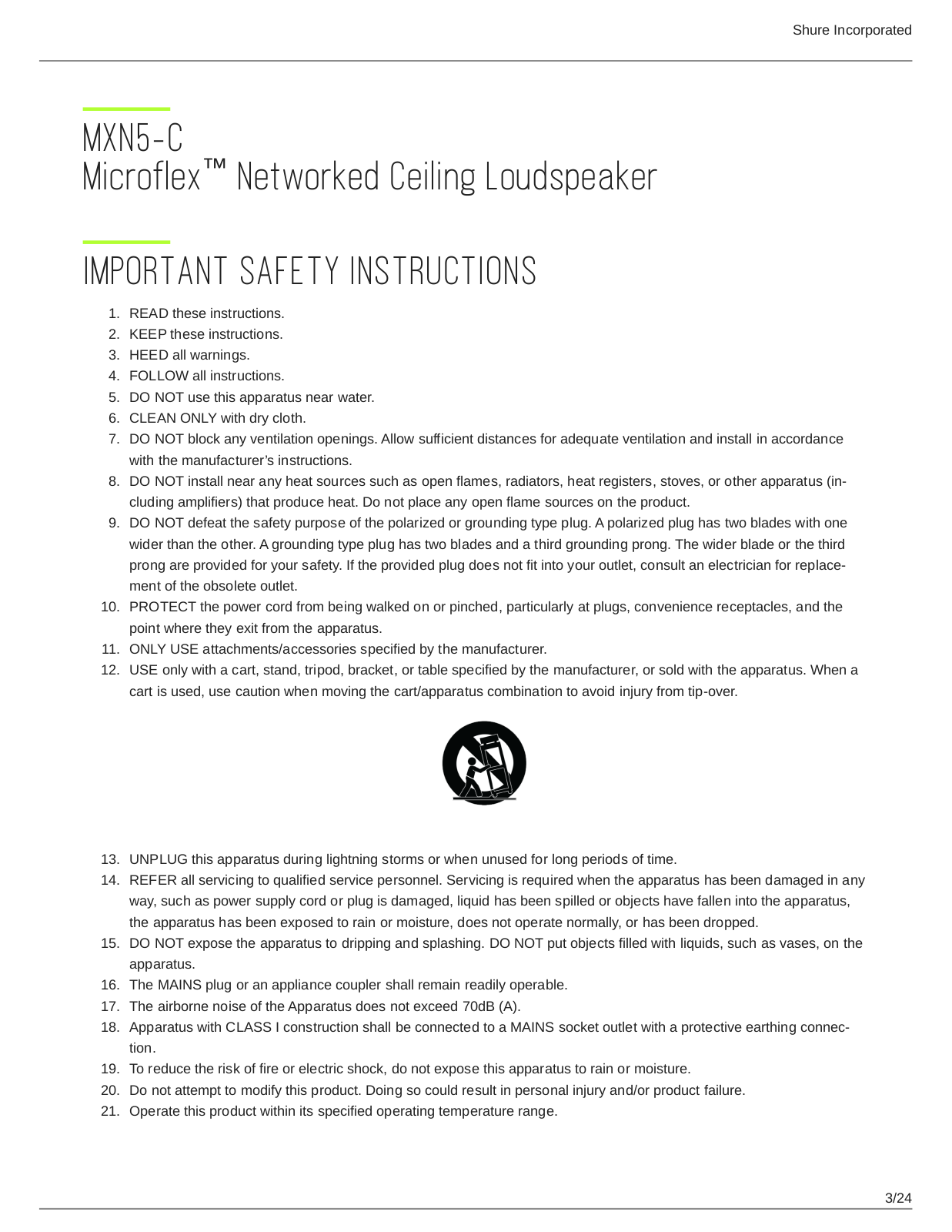
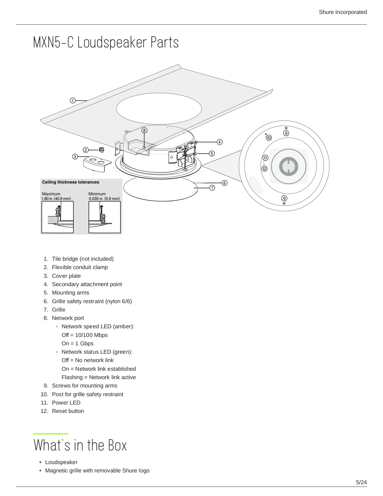
MXN5-C
User manual
24 pgs
2.08 Mb
0
User Manual
24 pgs
2.08 Mb
0
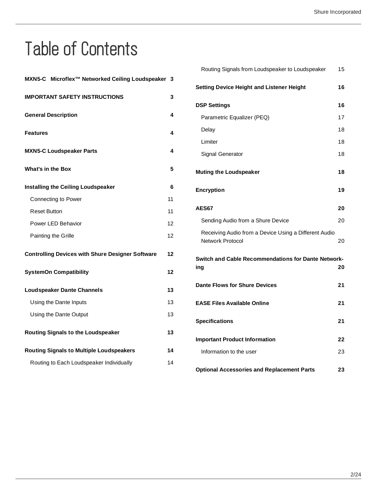
Table of contents
Loading...
Shure MXN5-C User Manual
...
Shure User Manual
Download
Specifications and Main Features
Frequently Asked Questions
User Manual
Download
Loading...
+
16
hidden pages
Unhide
You need points to download manuals.
1 point = 1 manual.
You can buy points or you can get point for every manual you upload.
Buy points
Upload your manuals
 Loading...