

Page 1
MX400D
www.shure.com
© 2009 Shure Incorporated
27A14051 (Rev. 2)
MX418D
MX412D
Printed in U.S.A.
Page 2
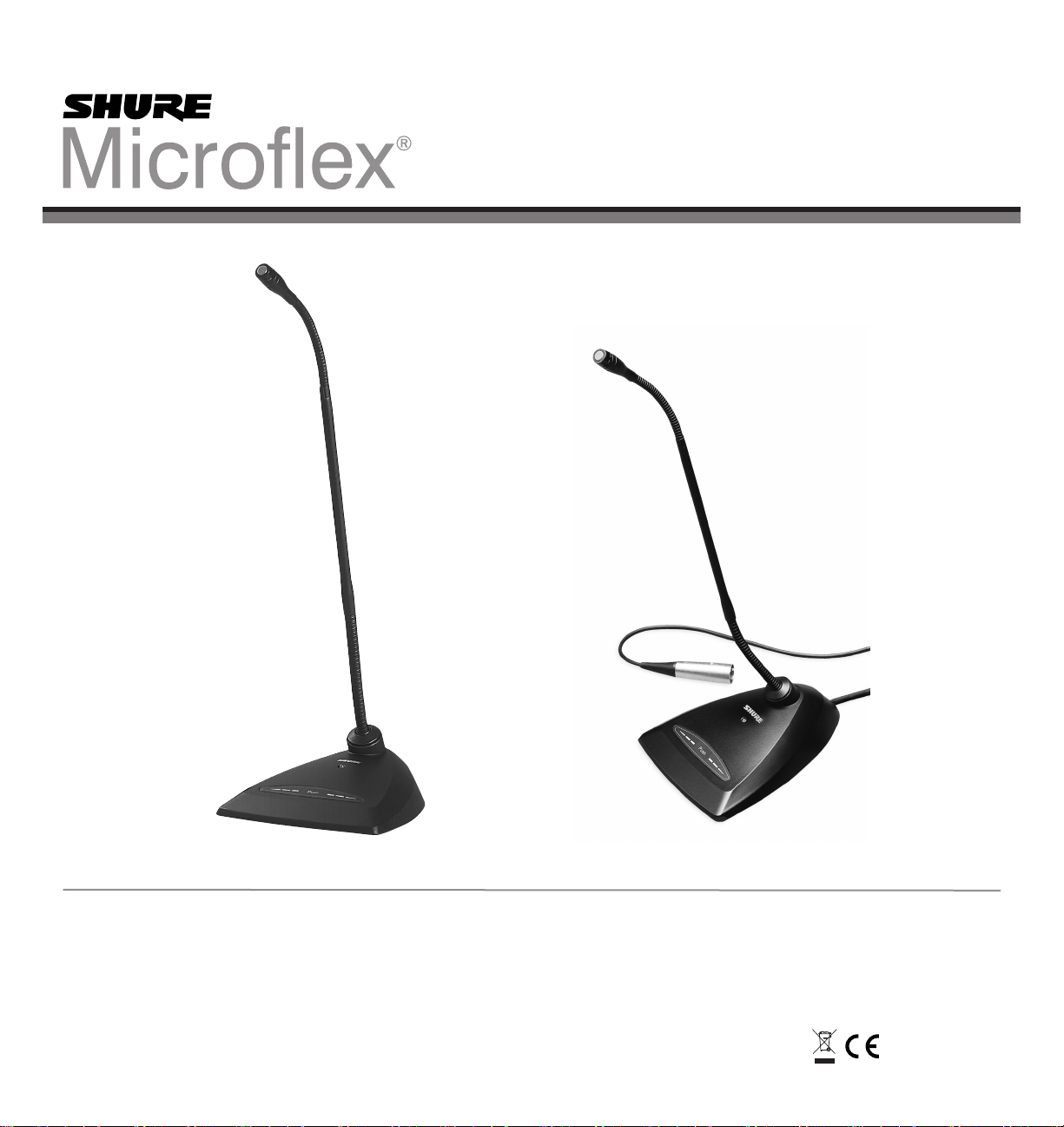
MX400D
Desktop Microphones
Shure Microflex® MX400D Series microphones
are miniature electret condenser gooseneck microphones with a desktop base and a 3 m (10 ft.)
cable. Desktop base allows microphones to be
used in multi-purpose rooms where quick setup
is required, or where permanent installation is
impractical.
Features
• Wide dynamic range and frequency response
for accurate sound reproduction
• Interchangeable cartridges that provide a
choice of polar pattern for each application
• Programmable mute button and LED indicator
• Logic input and output terminals for remote
control or use with automatic microphone
mixers
• Balanced, transformerless output for increased
immunity to noise over long cable runs
• RF filtering
MX400 Series Model Variations
MX400 microphones are available with 305 mm
(12 in.) or 457 mm (18 in.) goosenecks.
• “S” models include a mute button and LED.
• “D” models include a desktop base with
programmable mute button and LED and logic
input and output.
• “SE” models feature a surface mount flange
with side-exit cable.
The polar pattern of the included cartridge is indicated by a model number suffix:
/C Cardioid
/S Supercardioid
/N Cartridge not included
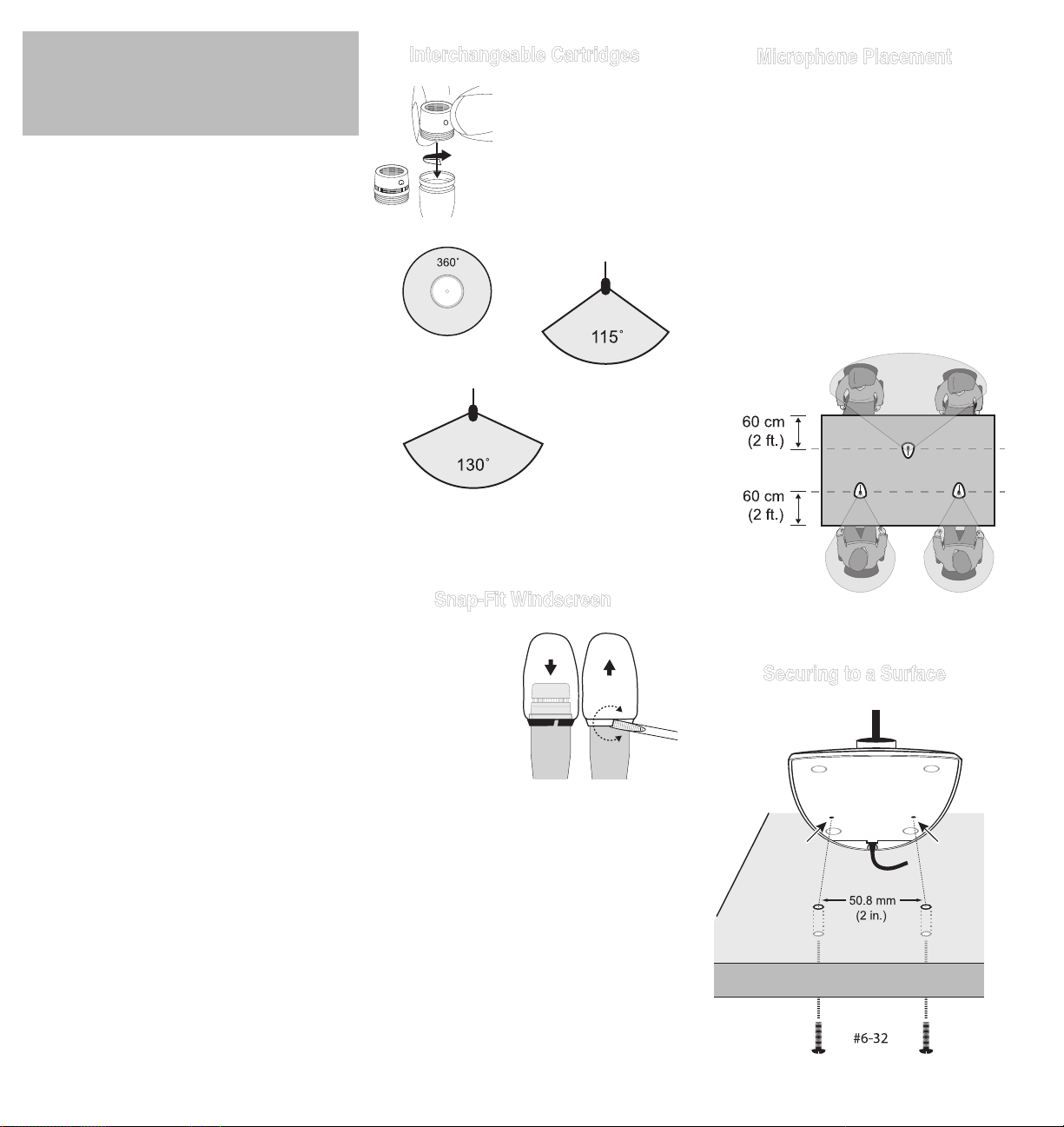
Interchangeable Cartridges
Microflex microphones use
interchangeable cartridges
that allow you to choose
the polar pattern for different installations.
R183 Omnidirectional
R184 Supercardioid
R185 Cardioid
Snap-Fit Windscreen
• Snap into the groove
below the cartridge.
• To remove, spread
the gap with a
screwdriver or
thumbnail.
• Provides 30 dB of
“pop” protection.
Microphone Placement
• Aim the microphone toward the desired source,
such as the talker.
• Aim it away from any unwanted source, such
as a loudspeaker.
• Place the microphone within 15 to 30cm (6 to
12 in.) of the desired sound source.
• Always use the supplied windscreen or optional
metal windscreen to control breath noise.
• If four or more microphones will be open at
the same time, use of an automatic mixer,
such as the Shure SCM810 or SCM410, is
recommended.
/C (R185)
/S (R184)
Securing to a Surface
2
Page 3
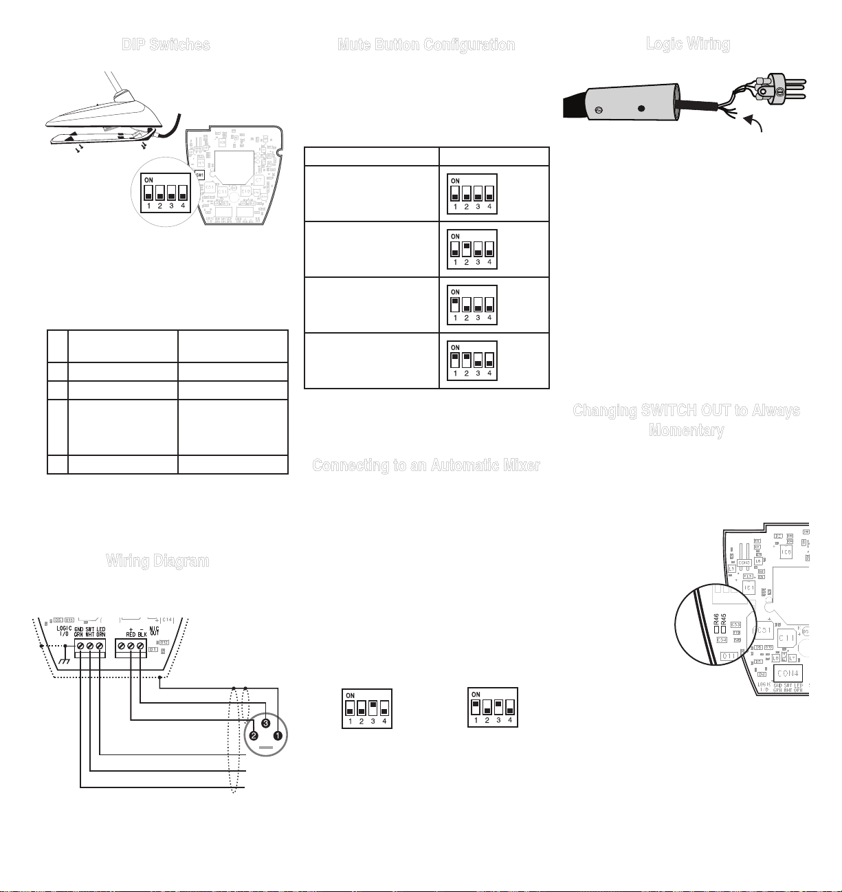
DIP Switches
Mute Button Configuration
Use DIP switches 1 and 2 to configure the mute
button, as follows.
Be sure to set DIP switch 3 off (factory default)
so that the mute button controls audio from the
microphone.
Logic Wiring
NOTE: Bottom
cover must
be closed for
microphone to
function.
Use the DIP switches to configure logic settings
and mute button behavior.
The DIP switches are covered with a piece of
clear tape at the factory. Remove tape to modify
the switch settings.
OFF (factory
default)
1 Momentary Toggle
2 Push-to-mute Push-to-talk
3 Mute button enabled,
LED illuminates when
mic is active
4 -- --
ON
Disable mute button
(microphone always
on), logic controls
LED
Wiring Diagram
NOTE: Audio and logic ground are connected at
microphone base.
Switch Function DIP Switch Setting
Momentary: push-to-mute
(as shipped).
Momentary: push-to-talk
Toggle: (Push On/Push
Off): Mic is active when
powered on
Toggle: (Push On/Push
Off): Mic is mute when
powered on
Connecting to an Automatic Mixer
Use these settings if connecting the microphone
to an automatic mixer or other device that mutes
audio and controls the LED.
1. Connect logic leads to the automatic mixer.
Connect the LED IN to the gate output to illuminate the LED when that channel is gated on.
2. Set DIP switch 3 on. This disbles the mute button (the microphone passes audio regardless of
whether the button is pressed or not).
3. Set DIP switch 1 to configure how the mute button sends SWITCH OUT logic:
Green (LOGIC GROUND): Connects to the logic
ground of an automatic mixer, switcher, or other
equipment.
Orange (LED IN): Set DIP switch 3 on to use LED
IN. When shorted to LOGIC GROUND, the LED
turns on.
White (SWITCH OUT): Provides TTL logic (0 Vdc
or 5 Vdc) in response to the mute button. Set DIP
switch 1 for momentary or toggle. When phantom
power is applied, logic initializes high (5 Vdc). DIP
switch 2 has no effect on SWITCH OUT.
Changing SWITCH OUT to Always
Momentary
Use the following modification in situations where
your logic interface requires momentary closure
of the SWITCH OUT, but you want the mute button to toggle the microphone (DIP switch 1 ON, 3
OFF):
1. Access the circuit board inside the microphone base.
2. Remove the resistor at R45
and reinstall it at location
R46.
Audio – (Black)
Audio + (Red)
LED IN (Orange)
SWITCH OUT (White)
Ground (Green)
Momentary:
push = 0 Vdc,
release = 5 Vdc
Toggle:
initial = 5 Vdc,
push = 0 Vdc
3
Page 4
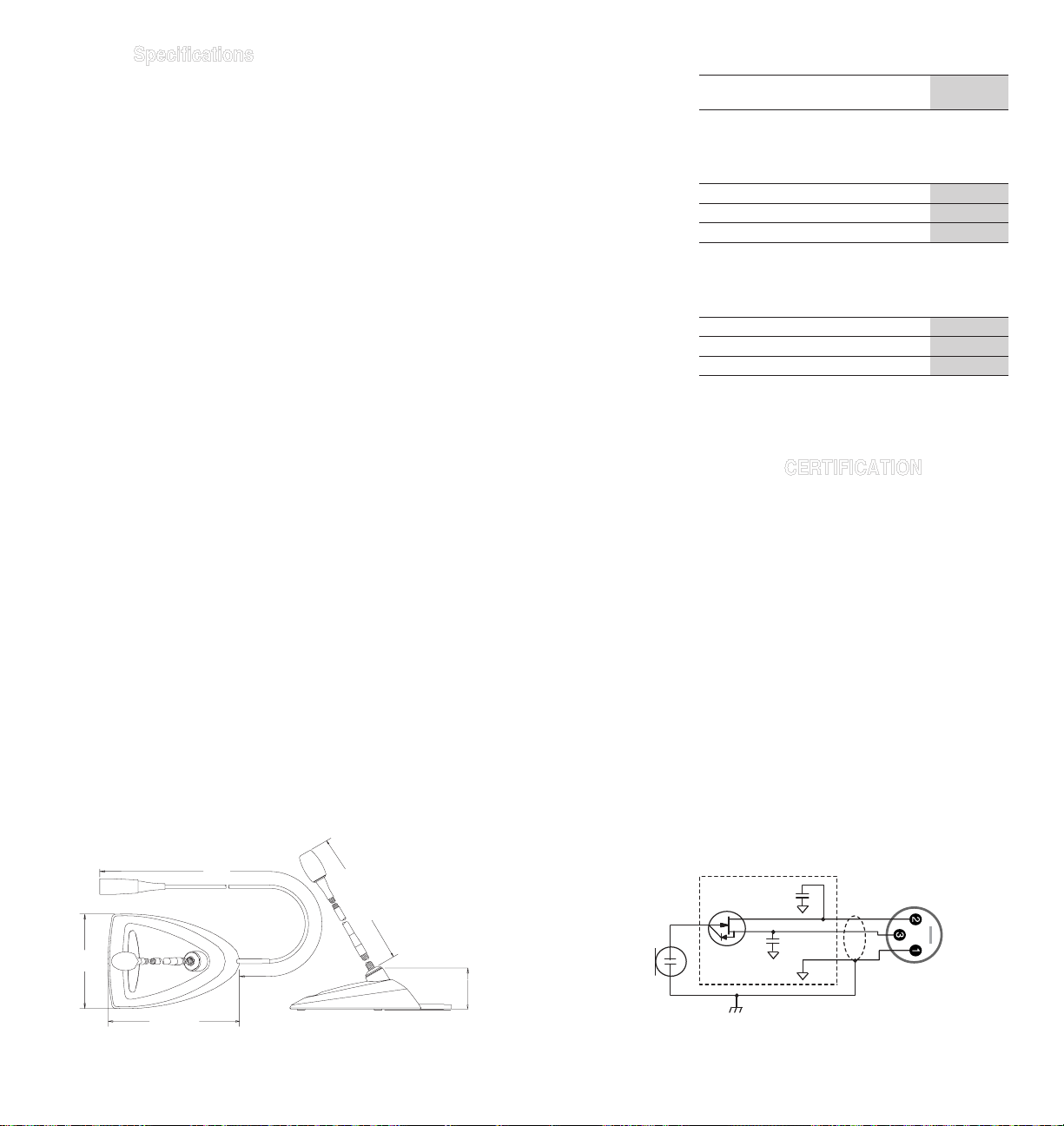
Specifications
Type
Condenser (electret bias)
Frequency Response
50–17000 Hz
Polar Pattern
MX412D/C, MX418D/C: Cardioid
MX412D/S, MX418D/S: Supercardioid
Output Impedance
EIARatedat150Ω(180Ωactual)
Output Configuration
Active balanced
Sensitivity (at 1 kHz , open circuit voltage)
Cardioid: –34 dBV/Pa (21 mV)
Supercardioid: –33 dBV/Pa (24 mV)
1 Pascal=94 dB SPL
Maximum SPL (1 kHz at 1% THD, 1 kΩ load)
Cardioid: 123 dB
Supercardioid: 122 dB
Equivalent Output Noise (A-weighted)
Cardioid: 29 dB SPL
Supercardioid: 28 dB SPL
Signal-to-Noise Ratio (referenced at 94 dB
SPL at 1 kHz)
Cardioid: 65 dB
Supercardioid: 66 dB
Dynamic Range (1 kΩ load at 1 kHz)
94 dB
Common Mode Rejection (10 Hz to 100 kHz)
45 dB minimum
Preamplifier Output Clipping Level (1% THD)
–6 dBV (0.5 V)
Polarity
Positive sound pressure on diaphragm produces
positive voltage on pin 2 relative to pin 3 of
output XLR connector.
Net Weight
MX412D: 0.81 kg (1.80 lbs)
MX418D: 0.82 kg (1.82 lbs)
Packaged Weight
MX412D: 1.63 kg (3.62 lbs)
MX412D: 1.64 kg (3.64 lbs)
Logic Connections
LED IN: Activelow(≤1.0V),TTLcompatible.
Absolute maximum voltage: -0.7V to 50V.
LOGIC OUT: Activelow(≤1.0V),sinksupto
20mA, TTL compatible. Absolute maximum
voltage:-0.7Vto50V(upto50Vthrough3kΩ).
Mute Switch Attenuation
–50 dB minimum
Cable
3 m (10 ft) attached cable with shielded audio
pair terminated at a 3-pin male XLR and three
unterminated conductors for logic control
Environmental Conditions
Operating Temperature: -18–57 °C (0–135 °F)
Storage Temperature: -29–74 °C (-20–165 °F)
Relative Humidity: 0–95%
Power Requirements
11–52 Vdc phantom, 2.0 mA
Furnished Accessories
Snap-fit Foam Windscreen (1 furnished, 4 in replacement kit)
RK412WS
Optional Accessories
Foam Ball Windscreen A99WS
Metal Locking Windscreen A412MWS
Custom Logic Cable (specify length) 95B2509
Replacement Parts
Omnidirectional Cartridge (Black) R183B
Supercardioid Cartridge (Black) R184B
Cardioid Cartridge (Black) R185B
CERTIFICATION
Eligible to bear CE Marking. Conforms to
European EMC Directive 2004/108/EC. Meets
Harmonized Standards EN55103-1:1996 and
EN55103-2:1996, for residential (E1) and light
industrial (E2) environments.
The Declaration of Conformity can be obtained
from:
Authorized European representative:
Shure Europe GmbH
Headquarters Europe, Middle East & Africa
Department: EMEA Approval
Wannenacker Str. 28
D-74078 Heilbronn, Germany
Phone: +49 7131 72 14 0
Fax: +49 7131 72 14 14
Email: EMEAsupport@shure.de
4
102.1 mm
(4 9/16 in.)
approximately 3 m
161.9 mm
(6 3/8 in.)
(10 ft)
MX412D: 355.4 mm (14 in.)
MX418D: 501.7 mm (19
3
/4 in.)
50.8 mm
(2 1/32 in.)
MIC
ELEMENT
FET
86E8958
220 pF
+
220 pF
Page 5
MX400D
Microphones de bureau
Les Microflex® série MX400D sont des microphones électrostatiques à électret miniatures à
col de cygne avec pied pour table et câble de 3
m (10 pi). Le pied de ces microphones permet de
les utiliser dans des salles polyvalentes, où une
installation rapide est nécessaire, ou lorsqu’une
installation permanente n’est pas pratique.
Fonctions
• Larges gamme dynamique et réponse en
fréquence pour une reproduction précise du
son
• Capsules interchangeables offrant un choix de
courbes de directivité pour chaque application
• Bouton de coupure du son programmable et
témoin DEL
• Bornes d’entrée/sortie logique pour
télécommande ou usage avec mélangeurs
automatiques
• Sortie équilibrée sans transformateur pour une
immunité aux bruits accrue avec de grandes
longueurs de fil
• Filtrage RF
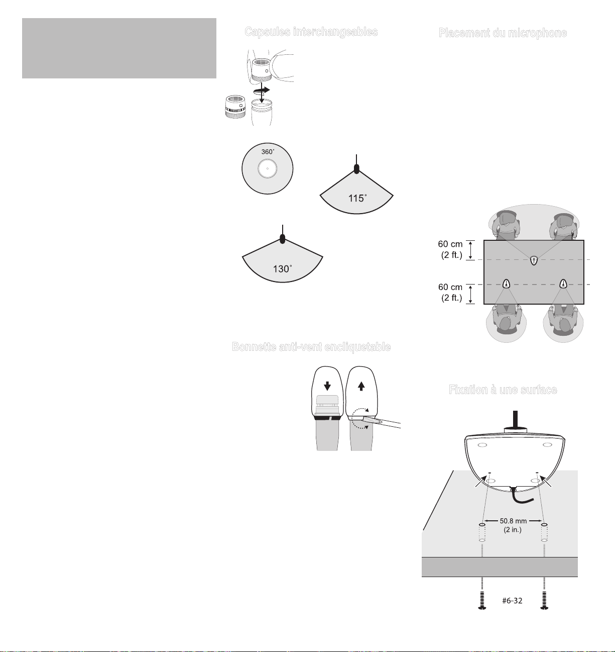
Capsules interchangeables
Les microphones Microflex
utilisent des capsules
interchangeables qui
permettent de choisir la
courbe de directivité pour
différentes installations.
R183 Omnidirectionnelle
R184 Supercardioïde
R185 Cardioïde
Placement du microphone
• Diriger le microphone vers la source désirée,
telle qu’un orateur.
• L’orienter à l’opposé de toute source
indésirable, telle qu’un haut-parleur.
• Placer le microphone à moins de 15 à 30 cm (6
à 12 po) de la source sonore désirée.
• Toujours utiliser la bonnette anti-vent fournie
ou la bonnette anti-vent en métal proposée
en option pour minimaliser les bruits de
respiration.
• Lorsque quatre microphones ou plus doivent
être ouverts simultanément, l’usage d’une table
de mélange automatique, telle que la Shure
SCM810 ou
SCM410, est
recommandé.
/C (R185)
MX400 Series Variantes
Les microphones MX400 sont disponibles avec
des cols de cygne de 305 mm (12 po) ou de 457
mm (18 po).
• Les modèles « S » comportent un bouton de
coupure du son et un témoin DEL.
• Les modèles « D » comportent un pied de table
avec bouton de coupure du son programmable
et témoin DEL ainsi qu’une entrée/sortie
logique.
• Les modèles « SE » comportent une bride
de montage en surface avec câble à sortie
latérale.
La courbe de directivité de la capsule incluse est
indiquée par le suffixe du numéro de modèle :
/C Cardioïde
/S Supercardioïde
/N Capsule non comprise
Bonnette anti-vent encliquetable
• Encliqueter dans la
gorge se trouvant
au-dessous de la
capsule.
• Pour la retirer,
agrandir
l’écartement avec un
tournevis ou l’ongle
du pouce.
• Assure une protection de 30 dB contre les
plosives.
/S (R184)
Fixation à une surface
5
Page 6
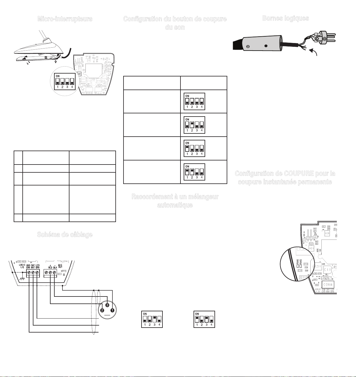
Micro-interrupteurs
Utiliser les micro-interrupteurs pour configurer les
réglages logiques et le comportement du bouton
de coupure du son.
Les micro-interrupteurs sont recouverts à l’usine
d’un morceau de ruban adhésif transparent.
Enlever le ruban adhésif pour changer les réglages d’interrupteur.
ARRÊT (défaut
usine)
1 Instantané Alternance
2 Appuyer pour couper
le son
3 Bouton de coupure
du son activé; le
témoin DEL s’allume
quand le micro est
actif
4 -- Modification spéciale
MARCHE
Appuyer pour parler
Bouton de coupure
du son désactivé (micro toujours activé);
la borne logique contrôle le témoin DEL
Schéma de câblage
REMARQUE : Le couvercle inférieur doit
être branché à la base du micro pour pouvoir
fonctionner.
Audio – (Noir)
Configuration du bouton de coupure
du son
Utiliser les micro-interrupteurs 1 et 2 pour configurer le bouton de coupure du son, comme suit.
Veiller à régler le micro-interrupteur 3 sur off
(défaut usine) de façon à ce que le bouton
de coupure du son contrôle le son à partir du
microphone.
Fonction d’interrupteur Réglage des mi-
cro-interrupteurs
Instantané : appuyer pour
couper le son (réglage
usine)
Instantané : appuyer pour
parler
Alternance : (appuyer
pour ouvrir/couper) : le
micro est actif quand sous
tension
Alternance : (appuyer pour
ouvrir/couper) : le micro
est coupé quand sous
tension
Raccordement à un mélangeur
automatique
Utiliser ces réglages pour raccorder le microphone à un mélangeur automatique ou un autre
appareil qui coupe le son et contrôle le témoin
DEL.
1. Connecter les bornes logiques au mélangeur
automatique. Raccorder l’entrée DEL à la sortie
d’obturateur pour que le témoin DEL s’allume
quand ce canal est activé.
2. Régler le micro-interrupteur 3 sur on. Ceci
désactive le bouton de coupure du son (le microphone fait passer le signal audio, que l’on
appuie sur le bouton ou non).
3. Régler le micro-interrupteur 1 pour configurer la
façon dont le bouton de coupure du son transmet la logique COUPURE :
Vert (MASSE LOGIQUE ): pour la connexion à la
masse logique d’un mélangeur automatique, d’un
commutateur ou d’un autre appareil.
Orange (ENTRÉE DEL ): Régler le micro-interrupteur 3 sur on pour utiliser ENTRÉE DEL. La
borne reçoit 5 V c.c. et en cas de court-circuit à
MASSE LOGIQUE, le témoin DEL s’allume.
Blanc (COUPURE ): procure un signal logique
TTL (0 V c.c. ou 5 V c.c.) en réaction au bouton
de coupure du son. Régler le micro-interrupteur 1 pour instantané ou alternance. Quand
l’alimentation fantôme est appliquée, la logique
s’initialise à la valeur haute (5 V c.c.). Le microinterrupteur 2 n’a aucun effet sur COUPURE.
Configuration de COUPURE pour la
coupure instantanée permanente
Utiliser la modification suivante dans les situations où l’interface logique requiert une fermeture
instantanée de COUPURE, mais que l’utilisateur
veut que le bouton de coupure du son fasse alterner le microphone (micro-interrupteur 1 ON, 3
OFF) :
1. Accéder au circuit imprimé
à l’intérieur de la base du
microphone.
2. Enlever la résistance à
R45 et la remettre à
l’emplacement R46.
Bornes logiques
Audio + (Rouge)
LED IN (Orange)
SWITCH OUT (Blanc)
6
Instantané : appuy-
er = 0 V c.c., relâch-
er = 5 V c.c.
Alternance : ini-
tial = 5 V c.c., ap-
puyer = 0 V c.c.
Page 7

Caractéristiques
Accessoires fournis
Type
Électrostatique (capsule électret)
Réponse en fréquence
50–17000 Hz
Courbe de directivité
MX412D/C, MX418D/C: Cardioïde
MX412D/S, MX418D/S: Supercardioïde
Impédance de sortie
NominaleEIA,150Ω(180Ωréelle)
Configuration de sortie
Symétrique active
Sensibilité (à 1 kHz, tension en circuit ouvert)
Cardioïde: –34 dBV/Pa (21 mV)
Supercardioïde: –33 dBV/Pa (24 mV)
1 Pascal=94 dB SPL
SPL maximum (1 kHz avec DHT de 1 %,
charge de 1 kΩ)
Cardioïde: 123 dB
Supercardioïde: 122 dB
Bruit de sortie équivalent (pondéré en A)
Cardioïde: 29 dB SPL
Supercardioïde: 28 dB SPL
Rapport signal/bruit (mesuré à 94 dB SPL à 1
kHz)
Cardioïde: 65 dB
Supercardioïde: 66 dB
Plage dynamique (charge de 1 kΩ à 1 kHz)
94 dB
Rejet en mode commun (10 Hz à 100 kHz)
45 dB minimum
Niveau d’écrêtage de sortie du préamplificateur (DHT de 1 %)
–6 dBV (0,5 V)
Polarité
Une pression acoustique positive sur le diaphragme produit une tension positive sur la broche 2
par rapport à la broche 3 du connecteur XLR de
sortie.
Poids net
MX412D: 0,81 kg (1,80 lb)
MX418D: 0,82 kg (1,82 lb)
Poids Emballé
MX412D: 1.63 kg (3.62 lbs)
MX412D: 1.64 kg (3.64 lbs)
Connexions logiques
LED IN (ENTRÉE DEL): Basniveauactivé(≤1,0
V), compatible TTL. Tension maximum absolue :
-0,7 V à 50 V.
LOGIC OUT (SORTIE LOGIQUE): Bas niveau
activé(≤1,0V),chuteà20mA,compatibleTTL.
Tension maximum absolue : -0,7 à 50 V (jusqu’à
50Và3kΩ).
Atténuation du bouton de coupure
–50 dB minimum
Câble
Câble fixe de 3 m (10 pi) à paire audio blindée
terminée à un XLR mâle à 3 broches et à trois
conducteurs sans terminaison pour la commande
logique
Environnement
Température de fonctionnement: -18–57 °C
(0–135 °F)
Température de stockage: -29–74 °C (-20–165
°F)
Humidité relative: 0–95 %
Alimentation
11–52 V c.c. fantôme, 2,0 mA
Bonnette anti-vent en mousse encliquetable (1 fournie, 4 dans le kit de
pièces de rechange)
RK412WS
Accessoires en option
Bonnette anti-vent sphérique en
mousse
Bonnette anti-vent verrouillable
métallique
Câble logique spécial (préciser la
longueur)
A99WS
A412MWS
95B2509
Pièces de rechange
Capsule omnidirectionnelle (noire) R183B
Capsule supercardioïde (noire) R184B
Capsule cardioïde (noire) R185B
HOMOLOGATION
Autorisé à porter la marque CE. Conforme à la directive européenne CEM 2004/108/CE. Conforme
aux normes harmonisées EN55103-1:1996 et
EN55103-2:1996 pour les environnements résidentiels (E1) et d’industrie légère (E2).
La déclaration de conformité peut être obtenue de
l’adresse suivante:
Représentant agréé européen :
Shure Europe GmbH
Siège Europe, Moyen-Orient et Afrique
Homologation EMEA
Wannenacker Str. 28
D-74078 Heilbronn, Germany
Phone: +49 7131 72 14 0
Fax: +49 7131 72 14 14
Email: EMEAsupport@shure.de
102.1 mm
(4 9/16 in.)
approximately 3 m
161.9 mm
(6 3/8 in.)
(10 ft)
MX412D: 355.4 mm (14 in.)
MX418D: 501.7 mm (19
3
/4 in.)
50.8 mm
(2 1/32 in.)
MIC
ELEMENT
FET
86E8958
220 pF
+
220 pF
7
Page 8

MX400D
Tischsockel-Mikrofone
Shure Microflex® Mikrofone der Reihe MX400D
sind Mini-Elektretkondensatormikrofone in
Schwanenhalsausführung mit einem Tischsockel
und einem 3 m langen Kabel. Der Tischsockel
ermöglicht die Verwendung dieser Mikrofone
in Mehrzweckräumen, in denen eine rasche
Aufstellung erforderlich ist oder in denen sich die
dauerhafte Anbringung als unpraktisch erweist.
Eigenschaften
• Breiter Dynamikbereich und Frequenzgang für
präzise Klangreproduktion
• Austauschbare Kapseln, die eine Auswahl
von Richtcharakteristiken für jeden
Verwendungszweck ermöglichen
• Programmierbare Stummschalttaste und
LED-Anzeige
• Eingabe- und Ausgabe-Logikanschlüsse
für Fernsteuerung und Gebrauch mit
automatischen Mikrofonmischstufen
• Ausgeglichene, transformatorlose Ausgabe
für gesteigerte Rauschunempfindlichkeit bei
langen Kabelführungen
• HF-Filterung
MX400 Series Modellvarianten
MX400 Mikrofone sind mit 305-mm- oder
457-mm-Schwanenhals erhältlich.
• „S“-Modelle verfügen über eine
Stummschalttaste und eine LED.
• „D“-Modelle enthalten einen Tischsockel mit
programmierbarer Stummschalttaste, LED und
Logik-Ein-/Ausgang.
• „SE“-Modelle weisen einen
Oberflächenmontage-Flansch mit seitlich
austretendem Kabel auf.
Die Richtcharakteristik der mitgelieferten Kapsel
wird durch das Modellnummer-Suffix angegeben:
/C Nierencharakteristik
/S Supernierencharakteristik
/N Kapsel nicht enthalten
Austauschbare Kapseln
Microflex Mikrofone weisen
austauschbare Kapseln
auf, die die Wahl der
Richtcharakteristik für verschiedene Einsatzzwecke
ermöglichen.
R183 Kugelcharakteristik
R184 Supernierencharakteristik
R185 Nierencharakteristik
Einrastender Windschutz
• In die Rille unter der
Kapsel einrasten
lassen.
• Zum Abnehmen
den Spalt mit einem
Schraubendreher
oder dem
Daumennagel
erweitern.
• Bietet 30 dB
Poppschutz.
Mikrofonaufstellung
• Das Mikrofon auf die vorgesehene Klangquelle,
beispielsweise den Vortragenden, richten.
• Es sollte weg von unerwünschten
Klangquellen, wie beispielsweise
Lautsprechern, weisen.
• Das Mikrofon in 15 bis 30 cm Entfernung von
der gewünschten Klangquelle anordnen.
• Stets den mitgelieferten Windschutz oder den
Metall-Windschutz (Sonderzubehör) benutzen,
um Atemgeräusche zu unterdrücken.
• Wenn vier oder mehr Mikrofone gleichzeitig
zum Einsatz kommen, wird die Verwendung
einer automatischen Mischstufe, z. B. Shure
SCM810 oder SCM410, empfohlen.
/C (R185)
/S (R184)
Befestigung an einer Oberfläche
8
Page 9

DIP-Schalter
Konfiguration der Stummschalttaste
Die Stummschalttaste wie folgt mit den DIPSchaltern 1 und 2 konfigurieren.
Den DIP-Schalter 3 unbedingt ausschalten
(Standardeinstellung ab Werk), so dass die
Stummschalttaste den Ton vom Mikrofon steuert.
Logikterminals
Die DIP-Schalter zur Konfiguration von
Logikeinstellungen und des Verhaltens der
Stummschalttaste verwenden.
Die DIP-Schalter werden ab Werk mit einem
transparenten Band abgedeckt. Zum Ändern der
Schaltereinstellungen das Band entfernen.
AUS (Standardeinstellung ab Werk)
1 Tastend (Momentan,
solange Taster
gedrückt)
2 Stummschalten auf
Tastendruck
3 Stummschalttaste ak-
tiviert, LED leuchtet,
wenn Mikrofon aktiv
ist
4 -- Kundenspezifische
EIN
Rastend
(Umschalten nach
Tasterbetätigung)
Sprechen auf
Tastendruck
Stummschalttaste
deaktivieren
(Mikrofon ist immer eingeschaltet),
Logikanschluss
steuert LED
Änderung der
Logikfunktion
Anschlussplan
HINWEIS: Audio- und Logikerdung sind am
Mikrofonsockel elektrisch verbunden.
Schalterfunktion Einstellung des
DIP-Schalters
Tastend (Momentan,
solange Taster gedrückt): Stummschalten
auf Tastendruck
(Werkseinstellung)
Tastend (Momentan, solange Taster gedrückt):
Sprechen auf Tastendruck
Rastend (Umschalten
nach Tasterbetätigung):
(Ein-/Ausschalten auf
Tastendruck): Mikrofon ist
beim Einschalten aktiv
Rastend (Umschalten
nach Tasterbetätigung):
(Ein-/Ausschalten auf
Tastendruck): Mikrofon
ist beim Einschalten
stummgeschaltet
Anschluss an eine automatische
Mischstufe
Diese Einstellungen verwenden, wenn das
Mikrofon an eine automatische Mischstufe oder
ein anderes Gerät angeschlossen wird, die bzw.
das den Ton stummschaltet und die LED steuert.
1. Die Logikterminals an die automatische
Mischstufe anschließen. LED IN mit dem GateAusgang verbinden, so dass die LED leuchtet,
wenn der Kanal angesteuert wird.
2. Den DIP-Schalter 3 einschalten. Dadurch wird
die Stummschalttaste deaktiviert (das Mikrofon
leitet den Ton weiter, egal ob die Taste gedrückt wird oder nicht).
3. Den DIP-Schalter 1 einstellen, um zu konfigurieren, wie die Stummschalttaste die SWITCH
OUT-Logik (Schalterausgang) sendet:
Grün (LOGIC GROUND (Logikmasse)): Stellt die
Verbindung zur logischen Masse einer automatische Mischstufe, eines Umschalters oder eines
anderen Geräts her.
Orange (LED IN (LED-Eingang)): Den DIPSchalter 3 einschalten, um LED IN zu verwenden.
Die Anschlussklemme zieht 5 Vdc, und wenn
sie mit LOGIC GROUND kurzgeschlossen wird,
leuchtet die LED auf.
Weiss (SWITCH OUT (Schalterausgang)): Stellt
TTL-Logik (0 Vdc oder 5 Vdc) als Reaktion auf
die Stummschalttaste bereit. Den DIP-Schalter
1 auf tastend oder rastend einstellen. Wenn
Phantomspeisung angelegt wird, wird die Logik
als hoch (5 Vdc) initialisiert. Der DIP-Schalter 2
hat keine Auswirkung auf SWITCH OUT.
Ändern von SWITCH OUT zu „Immer
tastend“
Die folgende Modifizierung in Situationen anwenden, in denen die Logik-Schnittstelle ein momentanes Schließen von SWITCH OUT erfordert,
aber die Stummschalttaste das Mikrofon rastend
umschalten soll (DIP-Schalter 1 EIN, 3 AUS):
1. Die Veränderung auf
der Leiterplatte im
Mikrofonsockel vornehmen.
2. Den Widerstand von R45
entfernen und in R46
einsetzen.
Audio – (Schwarz)
Audio + (Rot)
LED IN (Orange)
SWITCH OUT (Weiss)
Tastend (Momentan, so-
lange Taster gedrückt):
drücken = 0 Vdc,
freigeben = 5 Vdc
Rastend
(Umschalten nach
Tasterbetätigung):
anfänglich = 5 Vdc,
drücken = 0 Vdc
9
Page 10

Technische Daten
Type (Typ)
Kondensatormikrofon (Elektret)
Frequenzgang
50–17000 Hz
Richtcharakteristik
MX412D/C, MX418D/C: Niere
MX412D/S, MX418D/S: Superniere
Ausgangsimpedanz
EIA-Nennwert:150Ω(180ΩIst-Wert)
Ausgangskonfiguration
Aktiv symmetrisch
Empfindlichkeit (bei 1 kHz, Leerlaufspannung)
Niere: –34 dBV/Pa (21 mV)
Superniere: –33 dBV/Pa (24 mV)
1 Pascal=94 dB Schalldruckpegel
Maximaler Schalldruckpegel (1 kHz bei 1 %
Gesamtklirrfaktor, 1 kΩLast)
Niere: 123 dB
Superniere: 122 dB
Äquivalenzausgangsrauschen (mit
A-Gewichtung)
Niere: 29 dB Schalldruckpegel
Superniere: 28 dB Schalldruckpegel
Signalrauschabstand (bezogen auf 94 dB
Schalldruckpegel bei 1 kHz)
Niere: 65 dB
Superniere: 66 dB
Dynamikbereich (1 kΩ Last bei 1 kHz)
94 dB
Gleichtaktunterdrückung (mindestens 10 Hz
bis 100 kHz)
45 dB Minimum
Vorverstärkerausgang-Begrenzungspegel (1%
THD)
–6 dBV (0,5 V)
Polarität
Positiver Schalldruck an der Membran erzeugt
positive Spannung an Pin 2 in Bezug auf Pin 3
des XLR-Ausgangs.
Nettogewicht
MX412D: 0,81 kg
MX418D: 0,82 kg
Gewicht Verpackt
MX412D: 1.63 kg (3.62 lbs)
MX412D: 1.64 kg (3.64 lbs)
Logikanschlüsse
LED EIN: AktiverTiefpegel(≤1,0V),TTL-
kompatibel. Absolute Maximalspannung: -0,7 V
bis 50 V.
LOGIC OUT: AktiverTiefpegel(≤1,0V),sinkt
auf bis zu 20 mA ab, TTL-kompatibel. Absolute
Maximalspannung: -0,7 V bis 50 V (bis zu 50 V
beibiszu3kΩ).
Stummschalterbedämpfung
–50 dB Minimum
Kabel
3 m langes befestigtes Kabel mit abgeschirmtem Tonfrequenzpaar an einem 3-Pin-XLRStecker und drei unabgeschlossenen Leitern für
Logiksteuerung
Temperaturbereich
Betriebstemperatur: -18–57 °C
Lagerungstemperatur: -29–74 °C
Relative Feuchtigkeit: 0–95%
Versorgungsspannungen
11–52 V DC Phantomspeisung, 2,0 mA
Mitgeliefertes Zubehör
Einrastender Schaumstoff-Windschutz
(1 mitgeliefert, 4 in Ersatzpackung)
RK412WS
Sonderzubehör
Schaumstoff-Kugelwindschutz A99WS
Einrastender Metall-Windschutz A412MWS
Spezial-Logikkabel (bitte Länge
angeben)
95B2509
Ersatzteile
Kugelcharakteristikkapsel (Schwarz) R183B
Supernierenkapsel (Schwarz) R184B
Supernierenkapsel (Schwarz) R185B
ZERTIFIZIERUNG
Zur CE-Kennzeichnung berechtigt. Entspricht
der europäischen Richtlinie zur elektromagnetischen Verträglichkeit 2004/108/EG. Entspricht
den Anforderungen der harmonisierten Normen
EN55103-1:1996 und EN55103-2:1996 für
Wohngebiete (E1) und Leichtindustriegebiete
(E2).
Die Konformitätserklärung ist über die unten stehende Adresse erhältlich:
Bevollmächtigter Vertreter in Europa:
Shure Europe GmbH
Headquarters Europe, Middle East & Africa
Abteilung: EMEA-Zulassung
Wannenacker Str. 28
D-74078 Heilbronn, Germany
Tel: +49 7131 72 14 0
Fax: +49 7131 72 14 14
Email: EMEAsupport@shure.de
10
102.1 mm
(4 9/16 in.)
approximately 3 m
161.9 mm
(6 3/8 in.)
(10 ft)
MX412D: 355.4 mm (14 in.)
MX418D: 501.7 mm (19
3
/4 in.)
50.8 mm
(2 1/32 in.)
MIC
ELEMENT
FET
86E8958
220 pF
+
220 pF
Page 11

MX400D
Micrófonos de escritorio
Los micrófonos Microflex® serie MX400D de
Shure son micrófonos de condensador de electreto miniatura con cuello de cisne que tienen una
base para escritorio y un cable de 3 m (10 pies)
de largo. La base para escritorio permite usar estos micrófonos en salas de uso general, en situaciones en las cuales se requiere una instalación
rápida, o cuando una instalación permanente
resulta poco práctica.
Características
• Rango dinámico y respuesta de frecuencias
amplios para una reproducción sonora fiel
• Cápsulas intercambiables que permiten elegir
el patrón polar óptimo para cada aplicación
• Botón de silenciamiento programable y LED
indicador
• Bornes de entrada/salida lógica para
control remoto o para usarse con consolas
mezcladoras automáticas
• Salidas equilibradas sin uso de
transformadores para aumentar la inmunidad a
los ruidos en tramos largos de cable
• Filtrado de RF
MX400 Series Variedades de modelos
Los micrófonos MX400 se ofrecen con cuello de
cisne de 305 mm (12 pulg) ó 457 mm (18 pulg).
• Los modelos “S” incluyen botón de
silenciamiento y LED indicador.
• Los modelos “D” incluyen base para escritorio,
botón de silenciamiento programable con LED
y entrada/salida lógica.
• Los modelos “SE” incluyen una brida de
montaje en superficie y cable con salida por el
costado.
El patrón polar de captación de la cápsula incluida se designa por el sufijo que tiene en su
número de modelo:
/C Cardioide
/S Supercardioide
/N No incluye cápsula
Cápsulas intercambiables
Los micrófonos Microflex
emplean cápsulas intercambiables que le
permiten elegir el patrón
polar óptimo para cada
instalación.
R183 omnidireccional
R184 supercardioide
R185 cardioide
Paravientos de espuma de
colocación a presión
• Engánchelo en la
ranura que está
debajo de la cápsula.
• Para quitarlo, utilice
un destornillador o
la uña del dedo para
abrir la separación.
• Proporciona 30 dB
de protección contra
chasquidos.
Colocación del micrófono
• Oriente el micrófono hacia la fuente sonora
deseada, tal como un conferencista.
• Oriéntelo en sentido opuesto a fuentes no
deseadas, tales como un altavoz.
• Coloque el micrófono a una distancia de 15
a 30 cm (6 a 12 pulg) de la fuente sonora
deseada.
• Siempre use el paravientos provisto o el
paravientos metálico opcional para controlar el
ruido causado por el aliento.
• Si cuatro o más micrófonos estarán activos
simultáneamente, se recomienda usar una
consola mezcladora automática tal como la
SCM810 ó la SCM410 de Shure.
/C (R185)
/S (R184)
Montaje en una superficie
11
Page 12

Interruptores DIP
Utilice los interruptores DIP para configurar parámetros lógicos y el comportamiento del botón de
silenciamiento.
Los interruptores DIP se cubren con un trozo de
cinta adhesiva transparente en la fábrica. Quite la
cinta adhesiva para cambiar las posiciones de los
interruptores.
DESACTIVADO
(valor de fábrica)
1 Momentáneo Conmutador
2 Oprima para silenciar Oprima para hablar
3 Botón de silencia-
miento habilitado, el
LED se ilumina
cuando el micrófono
está activo
4 -- Modificación person-
ACTIVADO
Botón de silenciamiento inhabilitado
(el micrófono siempre
está activo), la entrada lógica controla
el LED
alizada de lógica
Diagrama de alambrado
NOTA: Las señales de tierra de audio y de
lógica se conectan eléctricamente en la base del
micrófono.
Audio – (Negro)
Configuración del botón de
silenciamiento
Utilice los interruptores DIP 1 y 2 para configurar el botón de silenciamiento, de la manera
siguiente.
Fije el interruptor DIP 3 en posición de desac-
tivado (valor de fábrica) para que el botón de
silenciamiento controle la señal de audio del
micrófono.
Función del interruptor Configuración de
interruptores DIP
Momentáneo: oprima para
silenciar (configuración de
fábrica).
Momentáneo: oprima para
hablar
Conmutador: (oprima para
encender/apagar): El micrófono está activo cuando
recibe alimentación
Conmutador: (oprima para
encender/apagar): El micrófono está silenciado cuando recibe alimentación
Conexión a consola mezcladora
automática
Utilice esta configuración si se va a conectar el
micrófono a una consola mezcladora automática
o a otro dispositivo que controla el silenciamiento
y el LED.
1. Conecte los bornes de la entrada lógica a la
consola mezcladora automática. Conecte la entrada LED IN a la salida de la compuerta, a fin
de que el LED se ilumine cuando el canal del
micrófono está activo.
2. Fije el interruptor DIP 3 en la posición de activado. Esto inhabilita el botón de silenciamiento
(el micrófono envía la señal de audio sin importar si el botón está oprimido o no).
3. Fije el interruptor DIP 1 para configurar cómo
envía el botón la señal lógica por la salida
SWITCH OUT:
Bornes lógicos
Verde (TIERRA LOGICA): Se conecta al conduc-
tor de puesta a tierra de los circuitos lógicos de
una consola mezcladora automática, conmutador
u otro equipo.
Anaranjado (LED IN): Coloque el interruptor DIP
3 en la posición de activado para usar la entrada
LED IN. Este borne tiene 5 VCC, y cuando se lo
pone en cortocircuito con TIERRA LOGICA, el
LED se ilumina.
Blanco (SWITCH OUT): Suministra una señal
lógica TTL (0 VCC ó 5 VCC) en respuesta al
botón de silenciamiento. Coloque el conmutador
DIP 1 en la posición de contacto momentáneo o
de conmutador. Cuando se aplica la alimentación
phantom, la señal lógica cobra valor inicial alto
(5 VCC). El interruptor DIP 2 no tiene efecto sobre la salida SWITCH OUT.
Configuración del borne de salida
del interruptor (SWITCH OUT)
para funcionamiento momentáneo
solamente
Utilice la modificación siguiente en situaciones en
las cuales el sistema lógico requiere que el borne
SWITCH OUT (salida del interruptor) se cierre momentáneamente, pero se desea que el
botón de silenciamiento conmute el estado del micrófono
(interruptor DIP 1 activado, 3 desactivado):
1. Acceda a la tarjeta
de circuitos que
está dentro de la
base del micrófono.
2. Retire la resistencia de la
posición R45 e instálela en
la posición R46.
12
Audio + (Rojo)
LED IN (Anaranjado)
SWITCH OUT (Blanco)
Momentáneo:
oprimido = 0 VCC,
suelto = 5 VCC
Conmutador:
inicial = 5 VCC,
oprimido = 0 VCC
Page 13

Especificaciones
Accesorios suministrados
Tipo
Condensador (electreto polarizado)
Respuesta de frecuencia
50–17000 Hz
Patrón polar
MX412D/C, MX418D/C: Cardioide
MX412D/S, MX418D/S: Supercardioide
Impedancia de salida
NominalsegúnEIA150Ω(180Ωreal)
Configuración de salida
Activa equilibrada
Sensibilidad (a 1 kHz, voltaje de circuito
abierto)
Cardioide: –34 dBV/Pa (21 mV)
Supercardioide: –33 dBV/Pa (24 mV)
1 Pascal=94 dB SPL
Nivel de presión acústica (SPL) máx. (1 kHz
con 1% THD, carga de 1 kΩ)
Cardioide: 123dB
Supercardioide: 122dB
Ruido equivalente de salida (Ponderación A)
Cardioide: 29 dB SPL
Supercardioide: 28 dB SPL
Relación de señal a ruido (con respecto a 94
dB SPL a 1 kHz)
Cardioide: 65dB
Supercardioide: 66dB
Rango dinámico (1 kΩ de carga a 1 kHz)
94dB
Rechazo en modo común (10 Hz a 100 kHz)
45 dB mínimo
Nivel de limitación de salida del preamplificador (1% THD)
–6 dBV (0,5 V)
Polaridad
Una presión positiva en el diafragma del micrófono produce un voltaje positivo en la clavija 2
con respecto a la clavija 3 del conector XLR de
salida.
Peso neto
MX412D: 0,81 kg (1,80 lb)
MX418D: 0,82 kg (1,82 lb)
Peso Embalado
MX412D: 1.63 kg (3.62 lbs)
MX412D: 1.64 kg (3.64 lbs)
Conexiones lógicas
ENTRADA DE LED: Se activa con nivel bajo
(≤1,0V),compatibleconTTL.Voltajemáximo
absoluto: -0,7V a 50V.
SALIDA LOGICA: Seactivaconnivelbajo(≤1,0
V), consume hasta 20 mA, compatible con TTL.
Voltaje máximo absoluto: -0,7 V a 50 V (hasta 50
Vconcargade3kΩ).
Atenuación introducida por interruptor
silenciador
–50 dB mínimo
Cable
Cable de 3 m (10 pies) conectado con par blindado equilibrado con conector XLR macho de 3
clavijas y tres conductores sin conexión terminal
para control lógico
Condiciones ambientales
Temperatura de funcionamiento: -18–57°C
(0–135°F)
Temperatura de almacenamiento: -29–74°C
(-20–165°F)
Humedad relativa: 0–95%
Requisitos de alimentación
11–52 VCC de alimentación Phantom, 2,0 mA
Paravientos de espuma con anillo
elástico (1 provisto, 4 en juego de
repuestos)
RK412WS
Accesorios opcionales
Paravientos de bola de espuma A99WS
Paravientos metálico trabable A412MWS
Cable para funciones lógicas especia-
les (especifique el largo)
95B2509
Repuestos
Cartucho omnidireccional (negro) R183B
Cartucho de supercardioide (negro) R184B
Cartucho de cardioide (negro) R185B
CERTIFICACIONES
Califica para llevar la marca CE. Cumple con
la directiva europea de EMC 2004/108/EC.
Satisface las normas armonizadas EN551031:1996 y EN55103-2:1996 para entornos de uso
residencial (E1) e industrial ligero (E2).
La declaración de conformidad se puede obtener
de la siguiente dirección:
Representante autorizado en Europa:
Shure Europe GmbH
Casa matriz para Europa, Medio Oriente y Africa
Aprobación para región de EMEA
Wannenacker Str. 28
D-74078 Heilbronn, Germany
Phone: +49 7131 72 14 0
Fax: +49 7131 72 14 14
Email: EMEAsupport@shure.de
102.1 mm
(4 9/16 in.)
approximately 3 m
161.9 mm
(6 3/8 in.)
(10 ft)
MX412D: 355.4 mm (14 in.)
MX418D: 501.7 mm (19
3
/4 in.)
50.8 mm
(2 1/32 in.)
MIC
ELEMENT
FET
86E8958
220 pF
+
220 pF
13
Page 14

MX400D
Microfoni da tavolo
I microfoni Shure Microflex® Serie MX400D sono
microfoni a collo d’oca a condensatore a elettrete
tipo miniatura dotati di base da tavolo e cavo da
3 m (10 piedi). La base da tavolo consente l’uso
dei microfoni in sale multifunzionali ove occorra
eseguire messe a punto rapide o dove non sia
possibile effettuare installazioni permanenti.
Caratteristiche
• L’intervallo dinamico e la risposta in frequenza
ampie consentono una precisa riproduzione dei
suoni.
• Le capsule intercambiabili forniscono una
gamma di diagrammi polari per ciascuna
applicazione.
• Sono presenti un pulsante di silenziamento
programmabile ed il relativo indicatore LED.
• Vi sono terminali di ingresso ed uscita logici per
la regolazione a distanza o si usa con i mixer
microfonici automatici.
• L’uscita bilanciata, senza trasformatore,
consente di ottenere una maggiore immunità
dal rumore in lunghi tratti di cavo.
• Filtro RF
MX400 Series Descrizione dei modelli
I microfoni MX400 sono disponibili con collo d’oca
da 305 mm (12 pollici) o 457 mm (18 pollici).
• I modelli “S” includono pulsante di
silenziamento e relativo LED.
• I modelli “D” includono una base da tavolo
con pulsante di silenziamento programmabile,
relativo LED ed ingresso e uscita logici.
• I modelli “SE” presentano una flangia per
montaggio superficie con cavo con uscita
laterale.
Il diagramma polare della capsula inclusa è indicato dal suffisso del numero di modello, come
indicato di seguito.
/C Cardioide
/S Supercardioide
/N Capsula non inclusa
Capsule intercambiabili
I microfoni Microflex
impiegano capsule intercambiabili che consentono
di scegliere il diagramma
polare appropriato per le
diverse installazioni.
R183 Omnidirezionale
R184 Supercardioide
R185 Cardioide
Antivento fissabile a scatto
• Fatelo scattare nella
scanalatura sotto la
capsula.
• Per rimuoverlo,
allargate lo spazio
mediante un
cacciavite o l’unghia
del pollice.
• Fornisce un filtro
antischiocco pari a
30 dB.
Posizionamento del microfono
• Rivolgete il microfono verso la sorgente sonora
desiderata, ad esempio l’oratore.
• Rivolgete il microfono dalla parte opposta a
qualsiasi sorgente non desiderata, ad esempio
l’altoparlante.
• Sistemate il microfono a non più di 15-30 cm
(6-12 pollici) dalla sorgente sonora desiderata.
• Usate sempre l’antivento in dotazione o
l’antivento in metallo opzionale per tenere sotto
controllo il rumore della respirazione.
• Se si terranno aperti quattro o più microfoni
contemporaneamente, si consiglia l’uso di un
mixer automatico, ad esempio Shure SCM810
o SCM410.
/C (R185)
/S (R184)
Fissaggio ad una superficie
14
Page 15

Interruttori DIP
Usate gli interruttori DIP per configurare le
impostazioni logiche e lo stato del pulsante di
silenziamento.
gli interruttori DIP vengono coperti in fabbrica con
del nastro trasparente. Rimuovete il nastro per
modificare le impostazioni degli interruttori.
OFF (impostazione predefinita di
fabbrica)
1 Momentaneo Attivazione/
2 Silenziamento medi-
ante pressione
3 Pulsante di silenzia-
mento attivato, il LED
si accende quando il
microfono è attivo
4 -- Modifica logica
ON
disattivazione
Attivazione mediante
pressione
Disattivazione del
pulsante di silenziamento (microfono
sempre acceso), il
terminale logico comanda il LED
personalizzata
Schema circuitale
NOTA – la massa audio e la massa logica sono
collegate elettricamente alla base del microfono.
Audio – (Nero)
Configurazione del pulsante di
silenziamento
Usate gli interruttori DIP 1 e 2 per configurare
il pulsante di silenziamento, come indicato di
seguito.
assicuratevi di impostare l’interruttore DIP 3 su off
(impostazione predefinita di fabbrica) in modo che
il pulsante di silenziamento comandi l’audio dal
microfono.
Funzione
dell’interruttore
Momentaneo: silenziamento mediante pressione
(impostazione di fabbrica).
Momentaneo: attivazione
mediante pressione
Attivazione/disattivazione:
(On mediante pressione/
Off mediante pressione): il
microfono è attivo quando
è acceso
Attivazione/disattivazione:
(On mediante pressione/
Off mediante pressione):
il microfono è silenziato
quando è acceso
Impostazione degli interruttori DIP
Collegamento al mixer automatico
Utilizzate queste impostazioni in caso di collegamento del microfono ad un mixer automatico o
altro dispositivo di silenziamento dell’audio e di
comando del LED.
1. Collegate i terminali logici al mixer automatico.
Collegate l’ingresso LED all’uscita di porta per
illuminare il LED quando è attivo quel canale.
2. Impostate l’interruttore DIP 3 su on. Ciò disattiva il pulsante di silenziamento (il microfono
trasferisce l’audio indipendentemente dallo
stato del pulsante, premuto o non premuto).
3. Impostate l’interruttore DIP 1 per configurare
la modalità di invio della logica dell’USCITA
INTERRUTTORE da parte del pulsante di
silenziamento.
Terminali logici
Verde (MASSA LOGICA): si collega alla massa
logica di un mixer automatico, commutatore o altra apparecchiatura.
Arancione (INGRESSO LED): impostate
l’interruttore DIP 3 su on per usare l’INGRESSO
LED. Il terminale assorbe 5 V c.c. e, se in cortocircuito alla MASSA LOGICA, il LED si accende.
Bianco (USCITA INTERRUTTORE): fornisce
logica TTL (0 V c.c. o 5 V c.c.) in risposta al pulsante di silenziamento. Impostate l’interruttore
DIP 1 in alto per l’azione momentanea o le due
posizioni. Se si applica alimentazione virtuale,
la logica si inizializza ad un livello alto (5 V
c.c.). L’interruttore DIP 2 non ha alcun effetto
sull’USCITA INTERRUTTORE.
Cambio dell’USCITA
INTERRUTTORE in azione
momentanea permanente
Usate le modifiche indicate di seguito nelle
situazioni in cui l’interfaccia logica in uso richiede la chiusura momentanea dell’USCITA
INTERRUTTORE, ma desiderate che il pulsante
di silenziamento attivi o disattivi il microfono (interruttore
DIP 1 ON, 3 OFF).
1. Accedete alla scheda circuitale all’interno della
base del microfono.
2. Rimuovete il
resistore in corrispondenza di R45
e rimontatelo in corrispondenza di R46.
Audio + (Rosso)
LED IN (Arancione)
SWITCH OUT (Bianco)
Momentaneo: pres-
sione = 0 V c.c., rilas-
cio = 5 V c.c.
Attivazione/disattivazione: iniziale = 5 V c.c.,
pressione = 0 V c.c.
15
Page 16

Dati tecnici
Tipo
A condensatore (polarizzazione a elettrete)
Risposta in frequenza
50–17000 Hz
Diagramma polare
MX412D/C, MX418D/C: Cardioide
MX412D/S, MX418D/S: Supercardioide
Impedenza di uscita
ValorenominaleEIAdi180Ω(valoreeffettivo
150Ω)
Uscita
Attivo, bilanciato
Sensibilità (a 1 kHz, tensione a circuito aperto)
Cardioide: –34 dBV/Pa (21 mV)
Supercardioide: –33 dBV/Pa (24 mV)
1 Pascal=94 dB di SPL
Livello di pressione sonora (SPL) massimo (1
kHz a 1% THD, carico di 1 kΩ)
Cardioide: 123dB
Supercardioide: 122dB
Rumore in uscita equivalente (ponderazione
A)
Cardioide: 29 dB di SPL
Supercardioide: 28 dB di SPL
Rapporto segnale/rumore (riferito a 94 dB di
SPL a 1 kHz)
Cardioide: 65dB
Supercardioide: 66dB
Gamma dinamica (carico di 1 kΩ a 1 kHz)
94dB
Reiezione di modo comune (10 Hz-100 kHz)
45 dB minimo
Livello di limitazione (clipping) all’uscita del
preamplificatore (1% di THD)
–6 dBV (0,5 V)
Polarità
Una pressione sonora positiva sul diaframma
produce una tensione positiva sul piedino 2 rispetto al piedino 3 del connettore XLR di uscita.
Peso netto
MX412D: 0,81 kg
MX418D: 0,82 kg
Peso Lordo
MX412D: 1.63 kg (3.62 lbs)
MX412D: 1.64 kg (3.64 lbs)
Collegamenti logici
Ingresso LED: Attivobasso(≤1,0V),compatibile
con TTL. Tensione massima assoluta: - 0,7 - 50
V.
Uscita LOGICA: Attivabassa(≤1,0V),as-
sorbimento fino a 20 mA, compatibile con TTL.
Tensione massima assoluta: -0,7 - 50 V (fino a
50Vcon3kΩ).
Attenuazione dell’interruttore di silenziamento
–50 dB minimo
Cavo
Cavo da 3 m non scollegabile, con doppino audio
schermato dotato di connettore XLR maschio a 3
piedini e tre conduttori senza terminazione per il
comando logico
Specifiche ambientali
Temperatura di funzionamento: -18–57 °C
Temperatura a magazzino: -29–74 °C
Umidità relativa: 0–95%
Alimentazione
Alimentazione virtuale a 11–52 V c.c., 2,0 mA
Accessori in dotazione
Antivento in schiuma fissabile a scatto
(1 in dotazione, 4 nel kit di ricambio)
RK412WS
Accessori opzionali
Antivento sferico in schiuma
poliuretanica
Antivento di bloccaggio in metallo A412MWS
Cavo logico personalizzato (specifica
lunghezza)
A99WS
95B2509
Parti di ricambio
Capsula omnidirezionale (nera) R183B
Capsula supercardioide (nera) R184B
Capsula cardioide (nera) R185B
OMOLOGAZIONI
Contrassegnabile con il marchio CE. Conforme
alla direttiva europea sulla compatibilità elettromagnetica 2004/108/CE. Conforme alle norme armonizzate EN55103-1:1996 ed EN55103-2:1996
per l’uso in ambienti domestici (E1) e industriali
leggeri (E2).
La dichiarazione di conformità può essere ottenuta da:
Rappresentante europeo autorizzato:
Shure Europe GmbH
Sede per Europa, Medio Oriente e Africa
Approvazione EMEA
Wannenacker Str. 28
D-74078 Heilbronn, Germany
Phone: +49 7131 72 14 0
Fax: +49 7131 72 14 14
Email: EMEAsupport@shure.de
16
102.1 mm
(4 9/16 in.)
approximately 3 m
161.9 mm
(6 3/8 in.)
(10 ft)
MX412D: 355.4 mm (14 in.)
MX418D: 501.7 mm (19
3
/4 in.)
50.8 mm
(2 1/32 in.)
MIC
ELEMENT
FET
86E8958
220 pF
+
220 pF
Page 17

MX400D
デスクトップマイクロホン
Shure Microflex®MX400Dシリーズマイクロホン
は、ミニエレクトレットコンデンサグースネック
型マイクロホンで、デスクトップベースと3mの
ケーブルが付属しています。デスクトップベー
スを使用することで、マイクロホンを迅速に設置
しなければならない多目的ルームなど、常設が難
しい場所で使用することができます。
機能
• 幅広いダイナミックレンジと周波数応答によ
り、正確な音響再生を実現
• 用途に合わせて極性パターンを選択できる交換
可能カートリッジ
• プログラム可能ミュートボタンとLEDインジ
ケータ
• リモートコントロールの論理入力/出力端子ま
たは自動ミキサーの使用
• 変圧器不要のバランス出力により、長いケーブ
ル使用時のノイズに対する電磁波耐性が向上。
• RFフィルタリング
MX400 Series モデル種類
MX400マイクロホンには、305mmまたは457mm
のグースネックが使用できます。
• SモデルにはミュートボタンとLEDがありま
す。
• Dモデルにはデスクトップベース、プログラム
可能のミュートボタンおよびLED、論理入力/
出力があります。
• SEモデルには表面取付けフランジと横出しケ
ーブルが採用されています。
付属カートリッジの極性パターンは、モデル番号
末尾に示されています:
/C カーディオイド
/S スーパーカーディオイド
/N 付属カートリッジなし
交換可能カートリッジ
Microflexマイクロホンは、
交換可能カートリッジを使
用し、設置環境に合わせて
極性パターンを選択するこ
とができます。
R183 無指向性
R184 スーパーカーディ
オイド
R185 カーディオイド
• マイクロホンを目的の音源(話し手など)に
• ラウドスピーカー等の不要な音源には向けない
• マイクロホンを、必要な音源から15~30cmの
• 付属のウィンドスクリーンまたはオプションの
• 一度に4個以上のマイクロホンを使用する場合
スナップフィットウィンドスクリーン
• カートリッジ下の溝
にはめ込みます。
• 外すには、ドライバ
ーや親指で隙間をこ
じ開けます。
• 30dBのポップ音防
止を提供します。
マイクロホンの配置
向けます。
ようにします。
距離に設置します。
金属製ウィンドスクリーンを必ず使用して、ブ
レスノイズを制御してください。
は、ShureSCM810またはSCM410などの自動
ミキサーを使用するようお勧めします。
/C (R185)
/S (R184)
表面への固定
17
Page 18

DIPスイッチ
ミュートボタン設定
DIPスイッチ1および2でミュートボタンを次のよ
うに設定します。
ミュートボタンがマイクロホンから音声を制御す
るよう、DIPスイッチ3はオフ(工場出荷時デフォ
ルト)であることを確認してください。
ロジック端子
ロジック設定とミュートボタンを設定するには
DIPスイッチを使用します。
DIPスイッチは、透明なテープで覆われて出荷さ
れます。スイッチ設定を変える際はテープを取
り除いてください。
OFF (工場出荷時デ
フォルト)
1 モメンタリ トグル
2 押してミュート 押して話す
3 ミュートボタンを有
効にしているとき、
マイクがアクティブ
の場合LEDが点灯し
ます。
4 -- カスタムロジック
ON
ミュートボタンを無
効にし(マイクロホ
ンは常にオン)、
ロジック端子がLED
を制御
変更
配線図
注意: 音声と論理接地は電気的にマイクロホン
ベースに接続されています。
スイッチ機能 DIPスイッチ設定
モメンタリ:押してミュー
ト(出荷時)
モメンタリ:押して話す
トグル:(押してオン/押し
てオフ):電源をオンにする
とマイクはアクティブに
なります
トグル:(押してオン/押し
てオフ):電源をオンにす
るとマイクはミュートに
なります
自動ミキサーへの接続
これらの設定は、自動ミキサー、または音声をミ
ュートしLEDを制御する他の装置にマイクロホン
を接続する場合に使用してください。
1. ロジック端子を自動ミキサーに接続します。
LEDINをゲート出力に接続すると、チャンネ
ルがゲートオンしたときにLEDが点灯します。
2. DIPスイッチ3をオンに設定します。これによ
りミュートボタンが無効になります(ボタンを
押しているかいないかに関わらずマイクロホン
は音を伝えます)。
3. DIPスイッチを1にセットし、ミュートボタン
がSWITCHOUTロジックを送る方法を設定し
ます:
緑色():自動ミキサー、切り換え装置、他の機器
のロジックアースに接続します。
オレンジ(LEDIN):DIPスイッチ3をオンにセッ
トしてLEDINを使用します。端子は5Vdcを出
し、LOGICGROUNDにショートしたとき、LED
がオンになります。
白(SWITCHOUT):ミュートボタンに反応して
TTLロジック(0Vdcまたは5Vdc)を提供しま
す。DIPスイッチ1をモメンタリまたはトグルに
セットします。ファンタム電源を使用したとき、
ロジックはハイ(5Vdc)で開始します。DIPス
イッチはSWITCHOUTに影響しません。
SWITCH OUTを常にモメンタリに変
更する
ロジックインターフェースがSWITCHOUTのモ
メンタリのクローズを要求し、ミュートボタンで
マイクロホンを切り替えたい場合(DIPスイッチ1
オン、3オフ)、次の変更を行ってください:
1. マイクロホンベースの回路板にアクセスしま
す。
2. R45の抵抗を取り外し、R46
に設置します。
18
音声–(黒色)
音声+(赤色)
LED IN (Orange)
SWITCHOUT(白)
モメンタリ:プッシ
ュ=0Vdc、リリー
ス=5Vdc
トグル:初
期=5Vdc、プッシ
ュ=0Vdc
Page 19

仕様
型
コンデンサー型(エレクトレットバイアス方式)
周波数特性
50–17000 Hz
指向特性
MX412D/C, MX418D/C: カーディオイド
MX412D/S, MX418D/S: スーパーカーディオイド
出力インピーダンス
180ΩでEIA定格(150 Ω実効)
出力構成
アクティブバランス
感度 (1 kHz、開回路電圧)
カーディオイド: –34 dBV/Pa (21 mV)
スーパーカーディオイド: –33 dBV/Pa (24 mV)
1 パスカル=94 dB SPL
最大SPL (1 kHz、1% THD、1 kΩ負荷)
カーディオイド: 123dB
スーパーカーディオイド: 122dB
等価出力ノイズ (Aウェイト)
カーディオイド: 29 dB SPL
スーパーカーディオイド: 28 dB SPL
S/N比 (94 dB SPL、1 kHzで参照)
カーディオイド: 65dB
スーパーカーディオイド: 66dB
ダイナミックレンジ (1 kΩ負荷、1 kHz)
94dB
同相信号除去比 (10 Hz ~ 100 kHz )
45 dB 以上
プリアンプ出力クリッピングレベル (1% THD)
–6 dBV (0.5 V)
極性
ダイヤフラムへの正の圧力により、XLR出力コネクタ
ーの3番ピンに対して2番ピンに正電圧が生成され
ます。
重 量
MX412D: 0.81 kg
MX418D: 0.82 kg
パッケージ込み
MX412D: 1.63 kg (3.62 lbs)
MX412D: 1.64 kg (3.64 lbs)
ロジックコネクター
LEDイン: アクティブロー (1.0 V以下)、TTL対応。絶対
最大電圧:-0.7 V ~ 50 V
ロジックアウト: アクティブロー (1.0 V以下)、最大20
mAまでシンク、TTL対応。絶対最大電圧:-0.7 V~50
V (3 kΩを介して最大50 V)。
ミュートスイッチアッテネーション
–50 dB 最低
ケーブル
3mの付属ケーブルは、オス型3ピンXLRで終端処理
のシールド付きオーディオペアおよびロジックコントロ
ールに非終端処理の3本のコンダクター付き。
環境条件
使用温度範囲: -18–57 °C
保存温度: -29–74 °C
相対湿度: 0–95%
使用電源
11–52 V dc 直流電流、ファンタム電源、2.0 mA
付属アクセサリー
スナップフィットフォームウィンド
スクリーン(1個同梱、4個入り交換
キット)
RK412WS
オプション・アクセサリー(別売)
フォームボールウィンドスクリーン A99WS
メタルロッキングウィンドスクリ
ーン
カスタムロジックケーブル(長さ指
定)
A412MWS
95B2509
交換部品
無指向性カートリッジ(黒色) R183B
スーパーカーディオイドカートリッ
ジ(黒色)
カーディオイドカートリッジ(黒
色)
R184B
R185B
認 証
CEマーキングに適格。欧州EMC指令2004/108/
ECに適合。住宅(E1)および軽工業(E2)環境に関
し、EN55103-1:1996およびEN55103-2:1996の整
合規格に対応。
適合宣言書は以下より入手可能です:
ヨーロッパ認定代理店:
Shure Europe GmbH
ヨーロッパ、中東、アフリカ地区本部:
部門:EMEA承認
Wannenacker Str. 28
D-74078 Heilbronn, Germany
Phone: +49 7131 72 14 0
Fax: +49 7131 72 14 14
Eメール:EMEAsupport@shure.de
102.1 mm
(4 9/16 in.)
approximately 3 m
161.9 mm
(6 3/8 in.)
(10 ft)
MX412D: 355.4 mm (14 in.)
MX418D: 501.7 mm (19
3
/4 in.)
50.8 mm
(2 1/32 in.)
MIC
ELEMENT
FET
86E8958
220 pF
+
220 pF
19
Page 20

o
180
o
150
+10
0
–10
50 100 20020
500 1,000 2,000 5,000 10,000
Hz
CARDIOID
CARDIOÏDE
CARDIOIDE
KARDIOID
CARDIOIDE
20,000
+10
0
–10
50 100 20020
500 1,000 2,000 5,000 10,000
Hz
SUPERCARDIOID
SUPERCARDIOÏDE
SUPERKARDIOID
SUPERCARDIOIDE
SUPERCARDIOIDE
20,000
+10
0
–10
OMNIDIRECTIONAL
OMNIDIRECTIONNELLE
ALLE RICHTUNGEN
500 1,000 2,000 5,000 10,00050 100 20020
Hz
OMNIDIRECCIONAL
OMNIDIREZIONALE
20,000
o
120
o
90
120
o
90
60
–20 dB
–15 dB
o
60
–10 dB
o
30
180
o
150
o
–20 dB
–15 dB
o
–10 dB
–5 dB
o
30
180°
150°
120°
90°
–20 dB
–15 dB
–10 dB
60°
–5 dB
30°
+5 dB
–5 dB
0
o
0
250 Hz
500 Hz
1000 Hz
o
150
o
30
250 Hz
500 Hz
1000 Hz
o
150
120
o
30
250 Hz
500 Hz
1000 Hz
SUPERCARDIOÏDE
SUPERKARDIOID
150°
120°
60°
30°
OMNIDIRECTIONNELLE
ALLE RICHTUNGEN
o
120
o
90
o
60
CARDIOID
CARDIOÏDE
KARDIOID
o
o
90
o
60
SUPERCARDIOID
90°
OMNIDIRECTIONAL
o
120
o
90
o
60
CARDIOIDE
CARDIOIDE
o
120
o
90
o
60
SUPERCARDIOIDE
SUPERCARDIOIDE
120°
90°
60°
OMNIDIRECCIONAL
OMNIDIREZIONALE
o
180
o
150
o
30
o
150
o
30
150°
–20 dB
–15 dB
–10 dB
–5 dB
–20 dB
–15 dB
–10 dB
180
–5 dB
180°
0
0
2500 Hz
6400 Hz
10000 Hz
o
2500 Hz
6400 Hz
10000 Hz
150°
o
150
o
120
o
90
o
60
o
30
o
150
o
120
o
90
o
60
o
30
120°
2500 Hz
6400 Hz
10000 Hz
90°
60°
30°
–20 dB
–15 dB
–10 dB
–5 dB
30°
+5 dB
SHURE Incorporated http://www.shure.com
United States, Canada, Latin America, Caribbean:
5800 W. Touhy Avenue, Niles, IL 60714-4608, U.S.A.
Phone: 847-600-2000
U.S. Fax: 847-600-1212
Intl Fax: 847-600-6446
Europe, Middle East, Africa:
Shure Europe GmbH, Phone: 49-7131-72140
Fax: 49-7131-721414
Asia, Pacific:
Shure Asia Limited, Phone: 852-2893-4290
Fax: 852-2893-4055
SHURE Incorporated http://www.shure.com
États-Unis, Canada, Amérique latine, Caraïbes:
5800 W. Touhy Avenue, Niles, IL 60714-4608, U.S.A.
Téléphone : 847-600-2000
Télécopie aux États-Unis : 847-600-1212
Télécopie internationale : 847-600-6446
Europe, Moyen-Orient, Afrique:
Shure Europe GmbH, Téléphone : 49-7131-72140
Télécopie : 49-7131-721414
Asie, Pacifique:
Shure Asia Limited, Téléphone : 852-2893-4290
Télécopie : 852-2893-4055
SHURE Incorporated http://www.shure.com
Estados Unidos, Canadá, Latinoamérica, Caribe:
5800 W. Touhy Avenue, Niles, IL 60714-4608, EE.UU.
Teléfono: 847-600-2000 (dentro de los EE.UU.)
Fax: 847-600-1212
Fax internacional: 847-600-6446
Europa, Medio Oriente, Africa:
Shure Europe GmbH, teléfono: 49-7131-72140
Fax: 49-7131-721414
Asia, Pacífico:
Shure Asia Limited, teléfono: 852-2893-4290
Fax: 852-2893-4055
SHURE Incorporated http://www.shure.com
Stati Uniti, Canada, America latina, Caraibi:
5800 W. Touhy Avenue, Niles, IL 60714-4608, U.S.A.
Numero telefonico: 847-600-2000
Fax U.S.A.: 847-600-1212
Fax internazionale: 847-600-6446
Europa, Medio Oriente, Africa:
Shure Europe GmbH, numero telefonico: 49-7131-72140
Fax: 49-7131-721414
Asia, Pacifico:
Shure Asia Limited, numero telefonico: 852-2893-4290
Fax: 852-2893-4055
 Loading...