

Page 1
© 2016 Shure Incorporated
27A14046 (Rev. 6)
MICROFLEX SERIES
MX200 SERIES
USER GUIDE
WIRED MICROPHONE
Printed in U.S.A.
Le Guide de l’Utilisateur
Guia del Usuario
Guida dell’Utente
Bedienungsanleitung
取扱説明書
Manual do Usuário
Page 2
• Wide dynamic range and frequency response
for accurate sound reproduction
• Interchangeable cartridges that provide a
choice of polar pattern for each application
• White or black finish that blends unobtrusively
with most surroundings
• RF filtering
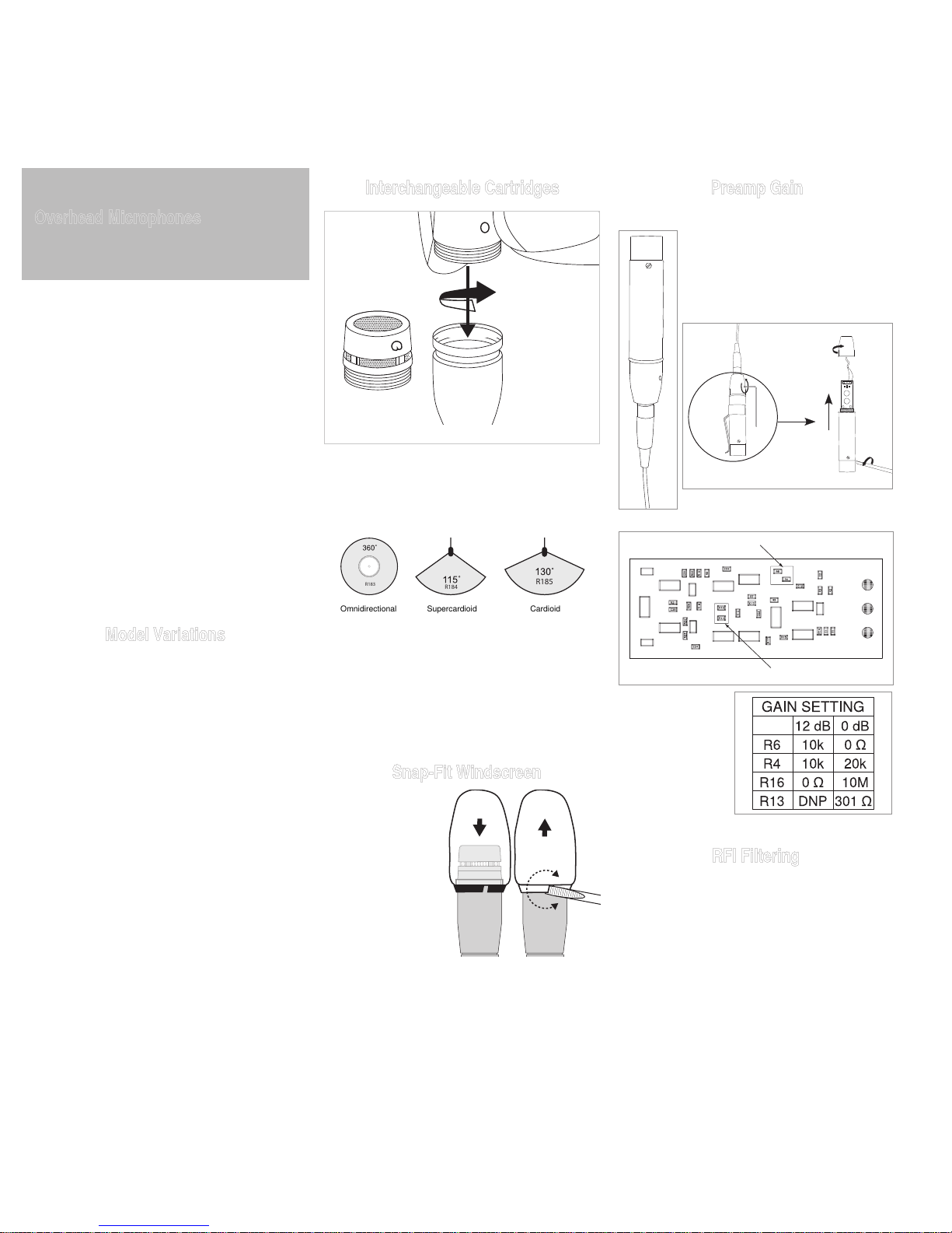
Model Variations
Microflex MX202 microphones are available in
black or white with a choice of in-line preamplifier
or plate-mount preamplifier.
The polar pattern of the included cartridge is indicated by a model number suffix:
/C Cardioid
/S Supercardioid
/N Cartridge not included
Interchangeable Cartridges
R183
R184
R185
Omnidirectional
Supercardioid
Cardioid
Cartridge Polar Patterns
Preamp Gain
If necessary, the preamplifier gain
can be reduced by 12 dB. Contact
an authorized Shure service center
for information.
RFI Filtering
Important: Microphones must be used with the
RK100PK and RK202PK plate-mounted preamp
to optimize RF immunity.
Overhead Microphones
MX200
Shure Microflex® MX200 Series microphones are
miniature electret condenser microphones designed for miking choirs and performance groups.
They are typically suspended over the heads of
the performers. Their high sensitivity and wide frequency range make them suitable for recording,
as well as sound reinforcement applications. An
attached 101 mm (4 in.) gooseneck allows them
to be easily aimed at the sound source.
Microflex microphones use interchangeable cartridges that allow you to choose the polar pattern
for different installations.
Snap-Fit Windscreen
• Snap into the
groove below the
cartridge.
• To remove, spread
the gap with a
screwdriver or
thumbnail.
• Provides 30 dB of
"pop" protection.
2
R6 and R4
R13 and R16
Q8
Q9
Q2
Q6
Q1
Q5
Q3
D1
Q4
Q7
C10
C11
C6
C9
C3
C11
Page 3
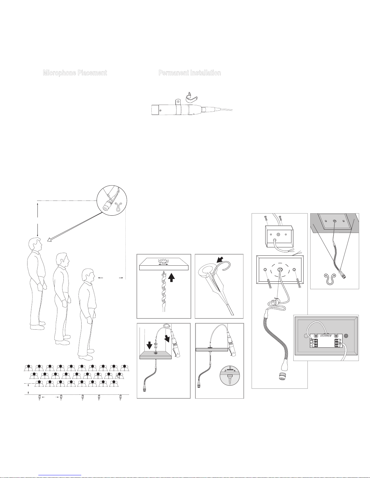
Microphone Placement
The microphone is most stable when the gooseneck is bent into a "lazy S" shape. Use the supplied hanging clip and heavy thread or monofilament fishing line to suspend the microphone at a
specific location.
• For choir installations, hang a microphone 0.6
to 0.9m (2 to 3 ft.) in front of the first row, and
0.6 to 0.9m (2 to 3 ft.) over the heads of the
singers in the last row. Aim the microphone at
the back row.
• When miking groups that move or vary in size,
use a boom stand and the supplied stand
adapter.
• If four or more microphones will be open at
once, an automatic mixer, such as the Shure
SCM810 or SCM410, is recommended. Set up
the automatic mixer so that all
overhead microphones gate
on simultaneously.
Permanent Installation
Installing the In-Line Preamp
Ceiling Tile Installation
1. Drill a 1/2 in. hole into the ceiling tile.
CAUTION: To avoid tile damage, use a 1/2 in.
augur bit and drill very slowly.
2. Unplug the mini 4-pin connector from the preamp and feed the cable through the hole.
3. Place the rubber grommet, tip down, over the
cable and position it to suspend the microphone at the appropriate height.
4. Fit the grommet securely into the hole. For 5/8
in. ceiling tile, use the suppled washer.
5. Reconnect the preamp.
The plate-mounted preamp allows you to mount
the preamp in an electical box and use conduit to
run cable through ceilings and walls.
1. Remove preamp housing by removing two phillips head screws.
2. Remove knock-out from the hole in the center
of the cover plate (if present).
3. Cut cable to desired hanging length, allowing
for a 76 to 101 mm (3 to 4 in.) service loop.
4. Clamp strain relief around cable and insert
strain relief into hole in plate.
5. Connect cable leads to input terminal block
(B = Black, R = Red, S = Shield).
6. Using professional-quality, two-conductor,
shielded microphone cable, thread output cable
from outside of preamp through hole with black
bushing.
7. Connect cable to output terminal block (Pin
2 = +, Pin 3 = –, Shield = S).
8. Reattach the preamplifier housing.
Use the two supplied mounting clamps to hold the
preamp in place on a wall or ceiling.
3
.6 – 1 m
(2 – 3 ft.)
.6 – 1 m
(2 – 3 ft.)
1.8 – 3m
(6 – 9 ft.)
0.6 – 1m
(2-3 ft.)
1/2"
INPUT OUTPUT
Page 4
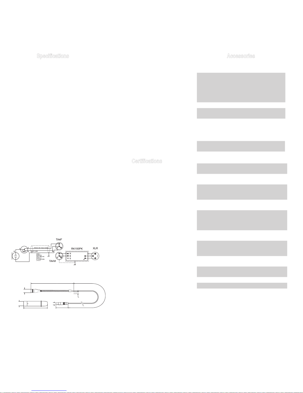
Specifications Accessories
Furnished Accessories
Black Snap-Fit Foam Windscreens
(4) for Beta 98, Beta 98A, Beta
98/S, Beta 98D/S, Beta 98H/C,
MX183, MX184, MX185, MX202,
WH30, WL183, WL184 and
WL185
RK183WS
White Snap-Fit Windscreen
95B2064
Preamplifier Kit, Plate Mounted,
White (MX202BP and MX202WP)
RK202PK
Stand Adaptor (MX202B and
MX202W)
65B1752
Optional Accessories
Small Black Desk/Table Stand for
MX202 Microphones
A202BB
Replacement Parts
RFI Resistant, Inline Preamp for all
MX Models (Black)
RK100PK
RFI Resistant, Inline Preamp for all
MX Models (White)
RK100PKW
Black or White Omnidirectional
Cartridge for all MX- (Microflex®)
Models and WL183
R183B
White Omnidirectional Cartridge for
MX- (Microflex®) Models
R183W
Black or White Supercardioid
Cartridge for all MX- (Microflex®)
and WL183, WL184 and WL185
Models
R184B
White Supercardioid Cartridge for
MX- (Microflex®) Models
R184W
Black or White Cardioid Cartridge
for WL185 and all MX- (Microflex®)
Models
R185B
White Cardioid Cartridge for MX-
(Microflex®) Models
R185W
Strain Relief (MX202BP and
MX202WP)
80A479
Clamp (MX202B and MX202WP)
80A476
Hang Clip
80B489
(30.0 ft.)
9.1 m
(5.69 in.)
144.5 mm
(1.39 in.)
35.4 mm
(0.23 in.)
5.8 mm
(0.46 in.)
11.7 mm
(.33 in.)
(0.75 in.)
19.0 mm
(4.00 in.)
101.6 mm
赤
NERO
RED
SCHWARZ NEGRO
Note: Yellowing of any plastic material can be
caused from cigarette smoke, ultra violet rays,
and other chemical interactions. Once plastic has
yellowed, there typically is no cleaning method
that will restore the whiteness.
Certifications
Meets essential requirements of all applicable
European Directives.
Eligible for CE marking.
The CE Declaration of Conformity can be obtained from: www.shure.com/europe/compliance
Authorized European representative:
Shure Europe GmbH
Headquarters Europe, Middle East & Africa
Department: EMEA Approval
Jakob-Dieffenbacher-Str. 12
75031 Eppingen, Germany
Phone: 49-7262-92 49 0
Fax: 49-7262-92 49 11 4
Email: [email protected]
4
Type
Condenser (electret bias)
Frequency Response
50–17000 Hz
Polar Pattern
MX202B/C, MX202W/C: Cardioid
MX202B/S, MX202W/S: Supercardioid
Output Impedance
EIA Rated at 150 Ω (180 Ω actual)
Output Configuration
Active balanced
Sensitivity (at 1 kHz , open circuit voltage)
Cardioid: –35 dBV/Pa (18 mV)
Supercardioid: –34 dBV/Pa (21 mV)
1 Pascal=94 dB SPL
Maximum SPL (1 kHz at 1% THD, 1 kΩ load)
Cardioid: 124 dB
Supercardioid: 123 dB
Equivalent Output Noise (A-weighted)
Cardioid: 28 dB SPL
Supercardioid: 27 dB SPL
Signal-to-Noise Ratio (referenced at 94 dB SPL
at 1 kHz)
Cardioid: 66 dB
Supercardioid: 68 dB
Dynamic Range (1 kΩ load at 1 kHz)
96 dB
Common Mode Rejection (10 Hz to 100 kHz)
45 dB minimum
Preamplifier Output Clipping Level (1% THD)
–6 dBV (0.5 V)
Polarity
Positive sound pressure on diaphragm produces
positive voltage on pin 2 relative to pin 3 of output XLR connector.
Cable
9 m (30 ft)
Environmental Conditions
Operating Temperature: -18–57 °C (0–135 °F)
Storage Temperature: -29–74 °C (-20–165 °F)
Relative Humidity: 0–95%
Power Requirements
11–52 Vdc phantom, 2.0 mA
Page 5
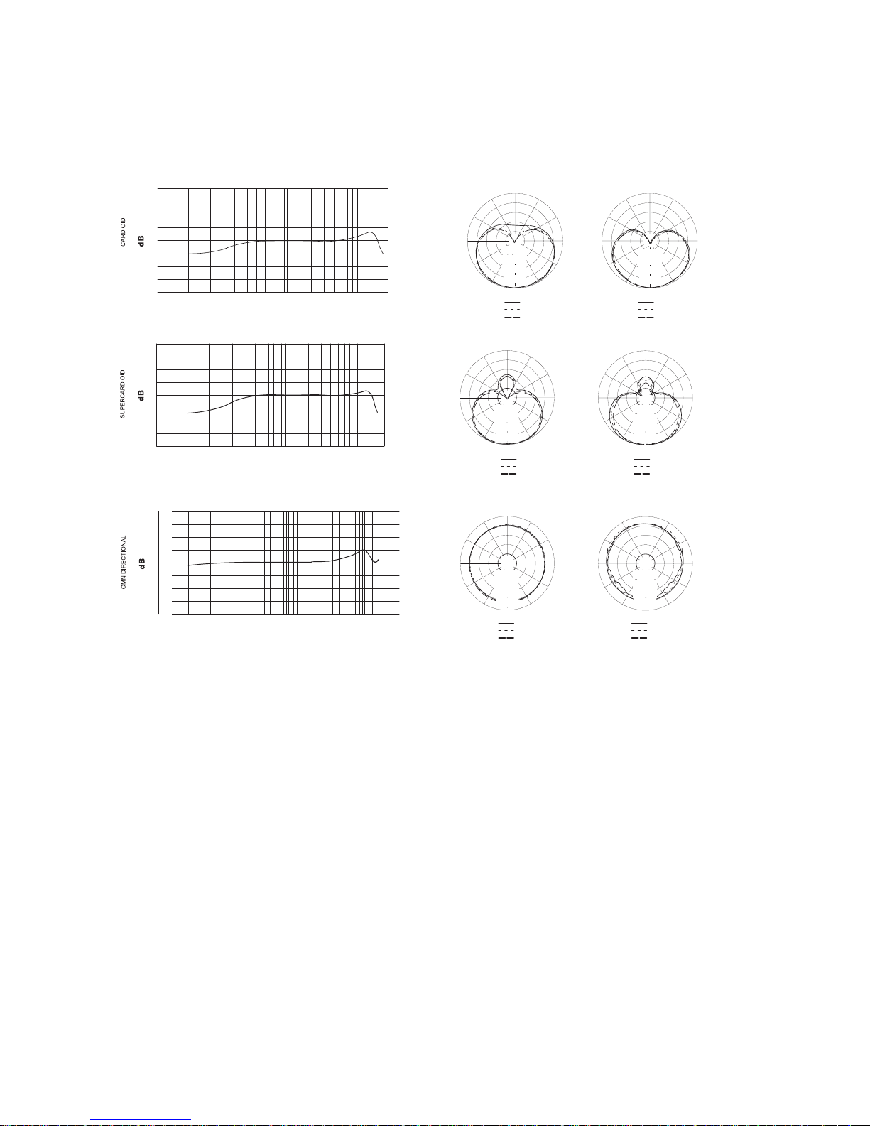
500 1,000 2,000 5,000 10,000
20,000
50 100 20020
0
+10
–10
250 Hz
500 Hz
1000 Hz
2500 Hz
6400 Hz
10000 Hz
150
o
120
o
150
o
120
o
180
o
30
o
60
o
90
o
30
o
60
o
0
90
o
150
o
120
o
150
o
120
o
180
o
30
o
60
o
90
o
30
o
60
o
0
–5 dB
–10 dB
–15 dB
90
o
–20 dB
–5 dB
–10 dB
–15 dB
–20 dB
Hz
150
o
120
o
150
o
120
o
180
o
30
o
60
o
90
o
30
o
60
o
0
150
o
120
o
150
o
120
o
180
o
30
o
60
o
30
o
60
o
–5 dB
0
90
o
–5 dB
–10 dB
–15 dB
90
o 90
o
500 1,000 2,000 5,000 10,000
20,000
50 100 20020
0
+10
–10
500 1,000 2,000 5,000 10,000
20,000
50 100 20020
0
+10
–10
250 Hz
500 Hz
1000 Hz
2500 Hz
6400 Hz
10000 Hz
250 Hz
500 Hz
1000 Hz
2500 Hz
6400 Hz
10000 Hz
150
o
120
o
150
o
120
o
180
o
30
o
60
o
90
o
30
o
60
o
0
90
o
150
o
120
o
150
o
120
o
180
o
30
o
60
o
90
o
30
o
60
o
0
–5 dB
–10 dB
–15 dB
90
o
–20 dB
–5 dB
–10 dB
–15 dB
–20 dB
–20 dB
–20 dB
–15 dB
–10 dB
Hz
Hz
150
o
120
o
150
o
120
o
180
o
30
o
60
o
90
o
30
o
60
o
0
150
o
120
o
150
o
120
o
180
o
30
o
60
o
30
o
60
o
–5 dB
0
90
o
–5 dB
–10 dB
–15 dB
90
o 90
o
500 1,000 2,000 5,000 10,000
20,000
50 100 20020
0
+10
–10
500 1,000 2,000 5,000 10,000
20,000
50 100 20020
0
+10
–10
500 1,000 2,000 5,000 10,00050 100 20020
0
+10
–10
250 Hz
500 Hz
1000 Hz
2500 Hz
6400 Hz
10000 Hz
250 Hz
500 Hz
1000 Hz
2500 Hz
6400 Hz
10000 Hz
250 Hz
500 Hz
1000 Hz
2500 Hz
6400 Hz
10000 Hz
150
o
120
o
150
o
120
o
180
o
30
o
60
o
90
o
30
o
60
o
0
150
o
120
o
150
o
120
o
180
o
30
o
60
o
30
o
60
o
–10 dB
–15 dB
0
90
o
–10 dB
–15 dB
–20 dB
90
o
150
o
120
o
150
o
120
o
180
o
30
o
60
o
90
o
30
o
60
o
0
90
o
150
o
120
o
150
o
120
o
180
o
30
o
60
o
90
o
30
o
60
o
0
–5 dB
–10 dB
–15 dB
90
o
90
o
20,000
–20 dB
–5 dB
–10 dB
–15 dB
–20 dB
–5 dB
–20 dB
–5 dB
–20 dB
–20 dB
–15 dB
–10 dB
Hz
Hz
Hz
Page 6

 Loading...