

Page 1
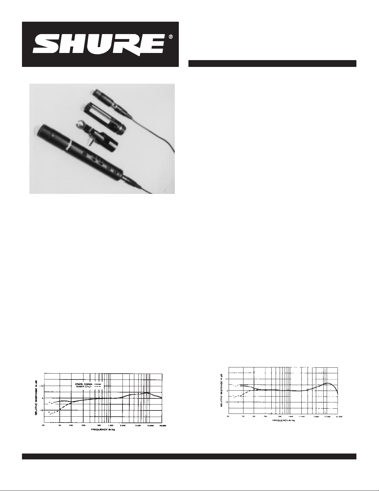
MODEL WM98 AND SM98A MINIATURE CONDENSER MICROPHONES
MICROPHONE
POLAR
MODIFIER
SWIVEL
ADAPTER
PREAMPLIFIER
GENERAL
microphones
wide frequency response from 40 to 20,000 Hz makes the microphones well suited for musical instrument pickup. The WM98 is for
wireless use; the SM98A is for wired applications. Both models feature
comin
reinforcement
20,000
instrument in an e
A98SPM Supercardioid Polar Modifier should be used. This devic e
changes
mal change of on-axis microphone frequency response. With the
A98SPM the 98 becomes the smallest multi-pattern microphone
available, eliminating the need for costly multiple capsules. The
A98SPM is supplied with the SM98A; it is an optional acc ess ory for
the
with
as well as brass, reed, wind, string, and keyboard instruments . The
98 ca
ter using the supplied cable; other transmitters must be checked for
proper pin configuration, condenser mic rophone power supply, and
connector
M
Shure
The
When still stronger rejection of off-axis pickup is required, the
A very high maximum sound pressure level allows use of the 98
The
odels WM9
w
the 9
8 m
icrophon
c
ardioi
d p
g from the r
a
Hz, the m
the p
W
M98.
all a
cousti
n also be used with a
W
M98 ca
t
ype.
8 and S
ith
a u
nidirectiona
e e
ola
r r
espons
ear
, p
ermittin
pplications
icrophone ca
nsembl
icku
p p
atter
c i
nstrument
n b
e c
onnecte
M98
A are m
l (
cardioid
lement.
e of the 9
g h
ighe
. With its true c
e o
r o
n f
rom cardioi
s i
ncludin
mplifie
r gain b
n o
fte
n b
rchestra.
g drum kits and o
d g
uitars and keyboards.
d d
irectl
iniatur
) p
icku
8 d
iscriminate
efor
ardioi
d t
o a S
o s
d p
upercardioi
hur
e used for p
y t
e e
p p
e f
atter
icku
e w
lectre
attern
s a
gains
eedbac
n e
p o
the
r p
ireles
t c
ondenser
. A s
mooth
t s
ounds
k i
n s
xtendin
f a p
articular
d with m
ercussion
s t
ransmit-
ound
g t
ini-
Shure
Brothers Incorporated
222 Hartrey A
venue
Evanston IL 60202-3696 U.S.A.
Models WM98 and SM98A User’s Guide
The WM9
for
m
with miniature 3– and 4–pin connectors (Switchcraft TA3 and TA4
types), and an acoustic foam winds creen to minimize wind noise in
outdoor
The
ered
included
alone, and a windscreen for use with the A98SPM, a shock-mount
swivel
“Tini Q–G” connectors.
The
switch-selectable
instruments. The Low-Cut pos ition is also useful to filter out low-frequency noise from such sources as wind nois e or air conditioner or
heater
tom
s
ment.
Optiona
and
S
• A98MK
ing
• A98KCS
cially
strument.
Microphone
o
• Smooth, wide frequency response for accurate sound repro-
duction
• Symmetrical
• Very
• V
• Low susceptibility to RFI, electrostatic and electromagnetic
hum
• Smallest
for
•
Rugged construction for outstanding reliability
• Cable
or
•
Usable over very wide range of temperature and humidity
• Supplied
on
•
Optional accessories to increase microphone versatility
8 i
s s
upplie
d w
ith
a v
ersatil
e s
ountin
g o
n a s
tandar
d 5
/8”–27 thread
a
pplications an
S
hur
e I
p
reamplifier
a
uppl
M98A
ery low distortion and high output clipping level
preamplifier (SM98A)
LP-1, low-distortio
a
ccessorie
dapte
r and a d
I
LP-
1 p
reamplifie
f
ans
. The I
y from s
l a
ccessories
, are a
Drum Kit, with gooseneck holder and clamp for mount
the microphone directly on most drums.
Horn Mount, a shock-mounted clamp designed espe
for securely mounting the 98 on a horn, wind, or reed in
Features:
across the entire audio spectrum
high sound pressure level capability
multi-pattern microphone available – without the need
multiple capsules
detachable at both microphone and transmitter (WM98)
with unique shock-mount swivel adapter for mounting
conventional microphone stands or goosenecks
d from a
, i
s f
urnishe
s are: a w
etachabl
r p
Flat o
r L
LP-
1 can be p
oun
d r
, d
vailable
cardioid pattern, uniform
ir–movin
n h
d with the S
indscree
e 4.6 m (15 ft) c
rovide
s s
ow-Cu
t r
owere
einforcement
esigne
d e
. T
hes
e i
hock–moun
, a 1.12 m (
g e
quipment.
igh-clipping-level
M98
A m
n for use with the m
witchabl
espons
d b
, r
ecording
xclusivel
nclud
icrophone
abl
e gain o
e t
o suit p
y any 11– t
, o
y for use with the W
e the f
ollowing:
with frequency to 20 kHz
e with S
o 5
r b
t s
wive
l a
3 f
t 8 in.) c
, p
hantom–pow-
. A
icrophone
witchcraft
f 0 o
r +10 d
icku
p for v
2–vol
t dc p
roadcas
dapter
able
dditional
B a
nd
arious
han-
t e
quip-
M98
-
-
-
TYPICAL FREQUENCY RESPONSE
1997 Shure Brothers Incorporated
27A2738
(QF)
FIGURE 1
TYPICAL FREQUENCY RESPONSE – SM98A WITH
A98SPM POLAR MODIFIER INSTALLED
FIGURE 2
Printed in U.S.A.
Page 2
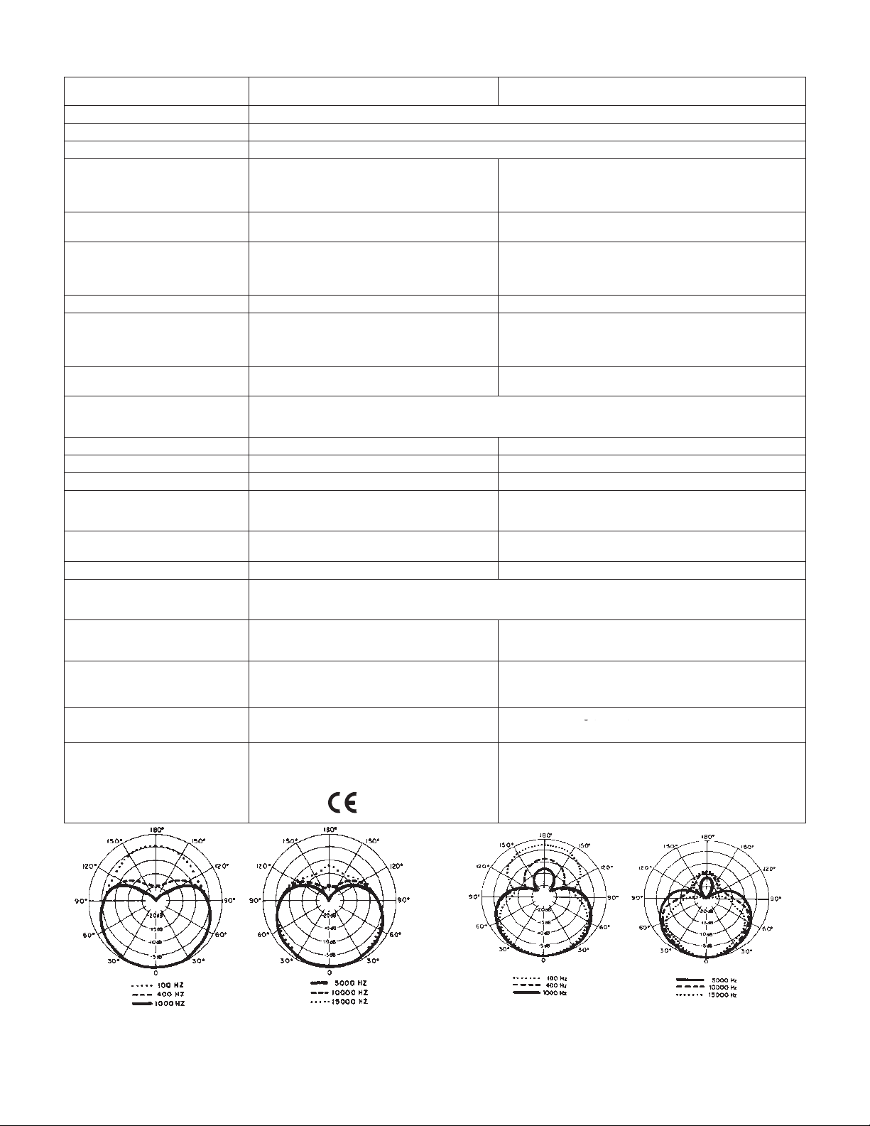
SPECIFICATIONS
g( )
Type
Frequency Response (Figs. 1–2)
Polar Pattern (Figs. 3–4) Unidirectional (cardioid) or supercardioid with A98SPM Supercardioid Polar Modifier
Output Impedance
Output Level
(0 dB = 1 volt per
Output
Clipping Level
(at 1,000 Hz)
Total
Harmonic Distortion
Maximum SPL
Dynamic Range (maximum SPL to
A-weighted
Output Noise (equivalent SPL)
Hum Pickup (electromagnetic)
Signal-to-Noise Ratio
Response Shaping
Phasing Positive
Recommended
Current Drain
Environmental Conditions Operating T
Cable Microphone
Case Microphone:
Net W
eight
Certifications Conforms to European Union directives,
bar)
noise level)
Operating V
oltage
WM98 MICROPHONE (with standard test circuit–Figure
1200
Open
–3 dBV (0.70 V)
Less than 1% (134 dB SPL at 1,000 Hz) Less than 1% (132 dB SPL at 1,000 Hz)
145 dB
11
1 dB
N/A
60 dB at 94 dB SPL (IEC 651) 60 dB at 94 dB SPL (IEC 651)
N/A Flat/Lo
duces positive voltage on pins 3 and 4 with respect
1.5 to 6 V (pin 2 to pins 3 and 4)
60 to 180
ductor,
nectors (Switchcraf
finish
Microphone: 12 g (0.4 oz) Microphone: 12 g (0.4 oz)
to
bear CE marking; meets European Union EMC
Immunity Requirements (EN 50 082–1, 1992);
RF
(IEC
6)
Ω
Circuit Voltage –74 dB (0.2 mV).
pressure on
to pin 1 (ground)
A
: 1
s
hielde
Brass construction with matte
and black stainless-steel-mesh grille
radiated (IEC 801–3); ESD
801–4).
. . . . . .
34 dB typical, A-weighted
40 dB typical, C-weighted
37 dB, weighted per DIN 45 405
microphone diaphragm pro
Storage
Relative
.12
m (
d with m
emperatures –18o to 57oC (0o to 135
T
emperatures –29o to 74oC (–20o to 168
Humidity
3 f
t 8 i
n.)
, a
ttached
e 3
– and 4
i Q–G” t
ype)
(IEC 801–2); EFT
t “
iniatur
Tin
.
. . . . . . . . . . . . . . . . . . . . . .
Condenser (electret bias)
40 to 20,000 Hz
. . . . . . . . . . . . . . . . . . . .
, t
wo-con-
–pi
eligible
SM98A MICROPHONE
Rated at 150 Ω (90 Ω actual)
Recommended minimum load impedance:
(May
be used with loads as low as 150 Ω with reduced
ping level)
Open Circuit V
800 Ω Load, ILP–1 gain = 0 dB
800 Ω
150 Ω
150 Ω Load ILP–1 gain = +10 dB
800
Ω
800
Ω
150 Ω
150 Ω
121 dB (800
–5 dB equivalent SPL in a 1 mOe field (60 Hz)
-
Positive
tive voltage on pin 2 relative to pin 3 of preamplifier output
connector
11 to 52 Vdc Phantom; operational down to 9 Vdc with reduced
2.2 mA current drain at 52 Vdc, 1.8 mA at 1
Microphone: 4.6
ture
n c
on-
black
3
–pi
en
d t
o mate with m
Microphone: Brass construction with matte black finish and
black
stainless-steel-mesh grille
Amplifier: Steel construction with matte black enamel finish
Amplifier: 170 g (6 oz)
oltage
.
Load, ILP–1 gain = +10 dB
Load ILP–1 gain = 0 dB
Load,
ILP–1 gain at 0 dB
Load,
ILP–1 gain at +10 dB
Load, ILP–1 gain at 0 dB
Load, ILP–1 gain at +10 dB
Ω
load,
ILP–1 gain at 0 dB)
Cut Preamp switch; Lo Cut: 12 dB rollof
pressure on microphone diaphragm produces posi
clipping level
o
F)
0 to 95% (operating or storage)
m (15 ft), t
n f
emal
e c
onnecto
icrophon
. . . . . .
wo-conductor
r (
Switchcraf
e o
–80 dB (0.10 mV)
.
. . . . . . . . . . .
.
. . . . . .
–13 dBV (0.22 V)
.
. . . . .
.
. . . . . . . . . . . . . . .
.
. . . . . . . . . . . . .
.
. . . . . . . . . . . . . . .
.
. . . . . . . . . . . . .
utpu
t and p
. . . . . .
0 dBV (1.0 V)
–7 dBV (0.45 V)
–21 dBV (0.09 V)
f below 80 Hz
1 Vdc
o
F)
, s
hielde
d with m
t T
A4F type
reamplifie
155 dB
138 dB
145 dB
127 dB
) o
n e
r i
nput
800
clip
inia-
Ω.
-
-
ach
TYPICAL POLAR PATTERNS
FIGURE 3
TYPICAL POLAR PA
TTERNS – SM98A WITH A98SPM
INSTALLED
FIGURE 4
2
Page 3
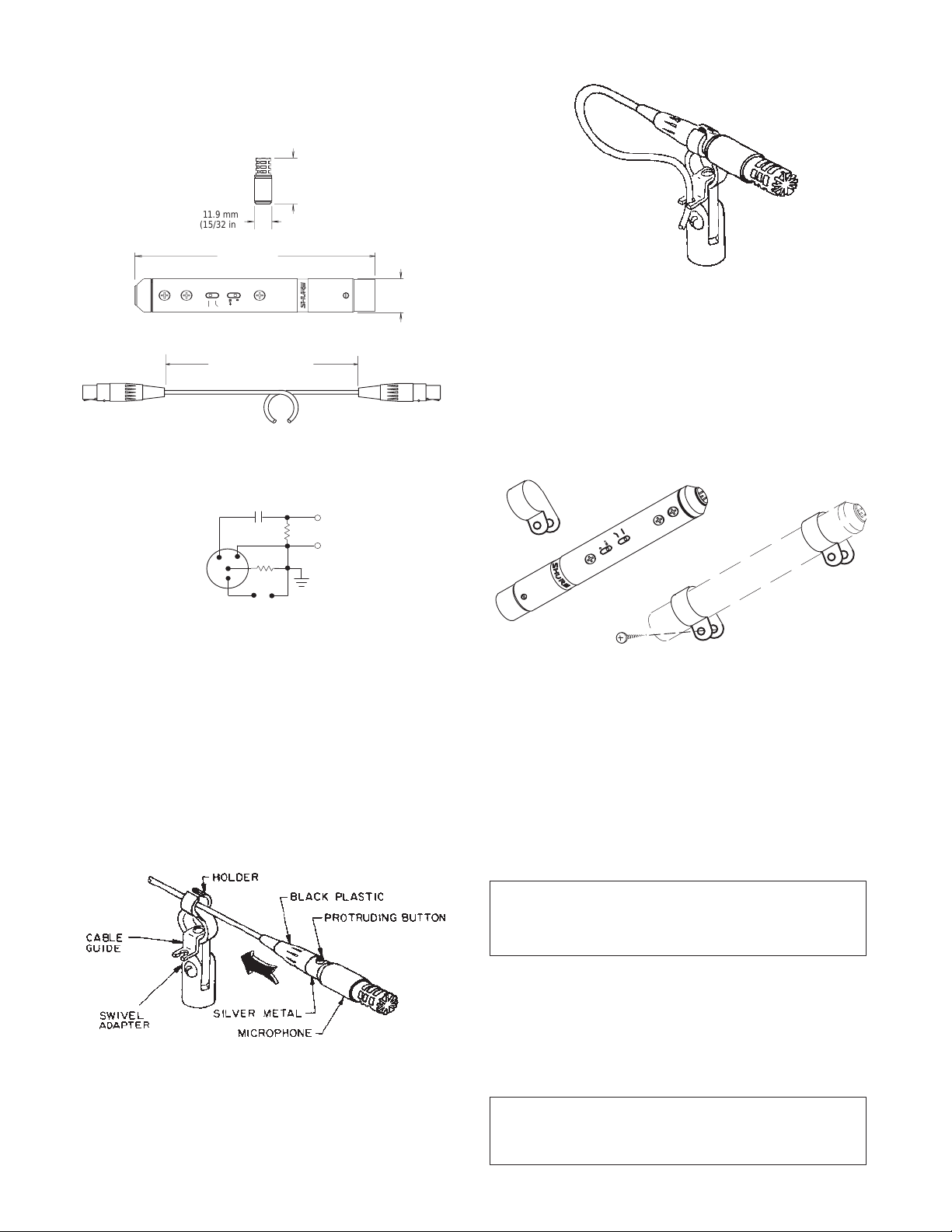
Dimensions
See Figure 5
138 mm
31.8 mm
(1-1/4 IN.)
(13/16
(WA330)
98 MICROPHONE
TA3F
1
1.9 mm
(15/32 in.)
(5-7/16 in.)
ILP–1 PREAMPLIFIER (SM98A)
WM98: 1.12 m (3 ft 8 in.)
SM98A: 4.6 m (15 ft)
OVERALL DIMENSIONS
FIGURE 5
1.0
WM98 ST
µF
100 K
20 K
1
3
4
2
5V
+
–
ANDARD TEST CIRCUIT
V out
FIGURE 6
INSTALLATION
mount the 98 in the supplied swivel adapter:
To
1.
Mount the adapter on a microphone stand.
2.
Attach the microphone to the connector
3.Slip
the cable through the slot in the adapter
back through the hole until the protruding black cable lock
tor
button
is in the open slot and the
stops
flush with the front of the holder
ment
of the connector is held by the holder (see Figure 7).
.
. Slide the connec
back of the microphone itself
. Only the silver metal seg
20 mm
TA4F
in.)
CABLE RETAINED IN GUIDE
FIGURE 8
5.T
ilt the adapter to aim the microphone as desired.
6.To
remove the microphone without disturbing the swivel adapt
and cable, reach into the open slot of the adapter and press
er
the
cable-lock button while disengaging the microphone.
PREAMPLIFIER PERMANENT MOUNTING (SM98A)
The
supplied mounting clamps are intended to hold the pre
amplifier in place in permanent installations (see Figure 9). Use
one or two clamps depending on location and application.
either
MOUNTING
CLAMPS – SM98A PREAMPLIFIER
FIGURE 9
PREAMPLIFIER SWITCHES
The
preamplifier case contains two miniature recessed slide
-
-
switches.
a
12 dB rollof
dB
Level
In the Lo Cut position, the Flat/Lo Cut switch
f below 80 Hz (see Figure 1). The ef
Gain switch are described in the
Preamplifier Output Clipping
specifications.
fects of the 0/+10
INSTALLING THE A98SPM
The A98SPM Supercardioid Polar Modifier is supplied with
the
SM98A and is an optional accessory for the
the
microphone in
an A98SPM Polar Modifier
WM98. T
, proceed as follows.
IMPORTANT
The white internal element of the A98SPM is essential to maintaining the supercardioid polar pat-
Do
not
tern.
remove it!
-
-
provides
o mount
SWIVEL ADAPTER MOUNTING
FIGURE 7
4.Slide
the cable through the slot in the cable guide and make a
large
loop (see Figure 8). Then route the cable away from the
stand to prevent transmission of noise and vibration through
the
cable.
3
1.Unscrew
rear
2.Insert
port
3.Attach
support
rattling.
the rear support from the front support by turning the
support counterclockwise (from bottom). See Figure 10.
the microphone (cable
not
connected) into the rear sup
with its connector end contacting the support.
the front and rear supports together by turning the
clockwise (from bottom). T
ighten
suf
ficiently to prevent
CAUTION
Do
not overtighten. Damage to the internal element
may
result.
-
rear
Page 4
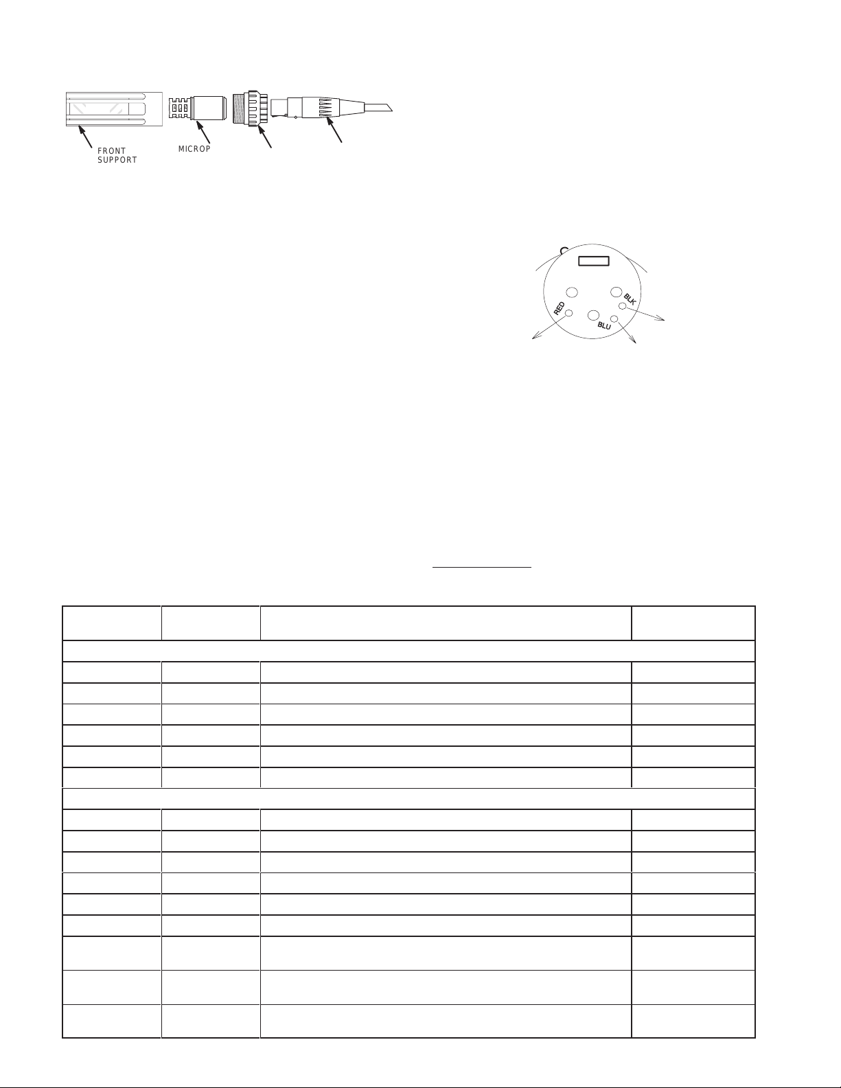
REASSEMBLING THE PREAMPLIFIER (SM98A)
sure
the pc board is seated in the slot of the end cap and
no wires are pinched.
the end cap-board assembly into the case, XLR connect
wires first. Again, take care not to pinch
the board to the end cap.
the assembly inside the case until the four
screws line up with the holes in the case.
the three lead wires to the back of the XLR board as
in Figure 1
1.
FRONT
SUPPORT
MICROPHONE
A98SPM
ASSEMBL
REAR
SUPPORT
Y
FIGURE 10
4.
Mount the swivel adapter on the microphone stand.
5.
Attach the microphone cable to the 98-A98SPM.
CABLE AND
CONNECTOR
1.Make
that
2.Insert
ing
ing
3.Rotate
lips
4.
Replace the four Phillips screws.
5.Resolder
shown
6.Mount the Microphone-Polar Modifier combination in the
adapter
7.T
as in steps 3 through 5 of the
o remove the microphone assembly from the swivel adapter
without disturbing the adapter and cable, reach into the open
slot
of the adapter and press the cable-lock button while
the microphone.
gaging
8.NOTE:
The Microphone-Polar
Modifier assembly can be used
with or without its supplied acoustic foam windscreen. When
mounted
vides
A98SPM
on the SM98A-A98SPM,
excellent wind and pop protection, but helps protect the
internal element from contamination.
DISASSEMBLING THE PREAMPLIFIER (SM98A)
1.At the XLR connector end of the preamplifier, turn the slotted
setscrew fully inward (counterclockwise), and use a long-
head
nose
pliers to carefully withdraw the connector from the case.
2.Unsolder the three lead wires securing the XLR connector to
the
XLR board.
3. Remove all four Phillips-head screws from the preamplifier
case
(three on the switch side, one on the back).
4.Grasp the end cap and withdraw the cap assembly, pc board
assembly,
Reference
Designation
and connecting wires and jacks from the case.
Part
Number
Installation
the windscreen not only pro
section.
disen
-
-
REPLACEMENT P
2
1
3
RED
BLUE
WIRING TO XLR PC BOARD TERMINALS
FIGURE 11
6.Replace
up
the XLR board-connector assembly in the case,
the key in the
connector with the slot in the case. T
not to engage the butterfly-shaped ground contact in the key
as it will prevent seating the connector properly
slot
7.Insert
the connector fully in the case until the slotted setscrew
can be seen in the case hole; tighten the setscrew firmly by
turning it clockwise.
OPTIONAL ACCESSORIES
Drum Mounting Kit
Horn
Clamp
Supercardioid
Windscreen
*Supplied with SM98A.
**Supplied with A98SPM.
(for A98SPM)**
. . . . . . . . . . . . . . . . . . . . . . . . . . . . .
. . . . . . . . . . . . . . . . . . . . . . . . . . . . . . . . . .
Polar Modifier*
. . . . . . . . . . . . . . . . . . .
. . . . . . . . . . . . . . . . . . . . . .
ARTS LIST
Description
Preamplifier (SM98A)
A1 90B4220
ILP-1 Preamplifier Assembly
None
A2 90HZ2600 Pc Board Assembly None
MP1 66A264
MP2 80A476
P1 95A8077 Plug Assembly
P2 90HV2600
Preamp Switch Cover
Mounting Clamp
, Male, Miniature 3–Pin
XLR-3M Connector and Pc Board Assembly
None
All States 3/4-HNB
Switchcraft TB3M
None
Microphone
MK1 R134
MP3 49A66A
MP4 A98SPM
MP5 49A82
MP6 RK282
P1 95A8077 Plug Assembly
Part of W1
WA330 Connector
Microphone Cartridge-Housing
Windscreen, Microphone
Supercardioid Polar Modifier (optional for WM98)
Windscreen, Polar Modifier (optional for WM98)*
Swivel Adapter
, Male, Miniature 3–Pin
, Female, Miniature, 4–Pin
None
None
None
None
None
Switchcraft TB3M
Switchcraft TA4F
(WM98)
W1 (SM98A)
W1 (WM98)
C107
90A4039
Cable–connector assembly
, 4.6 m (15 ft), two-conductor
shielded, 3-pin (female) Switchcraft “T
Cable–connector assembly
, 1.47 m (5 ft .), two conductor
shielded, 3– and 4–pin Switchcraft “T
4
ini Q–G” connectors
ini Q–G” connectors
,
,
None
None
the wires connect
holes for Phil
BLACK
.
Commercial
Alternate
-
-
-
lining
ake care
A98MKS.
A98KCS.
A98SPM.
49A82.
Page 5
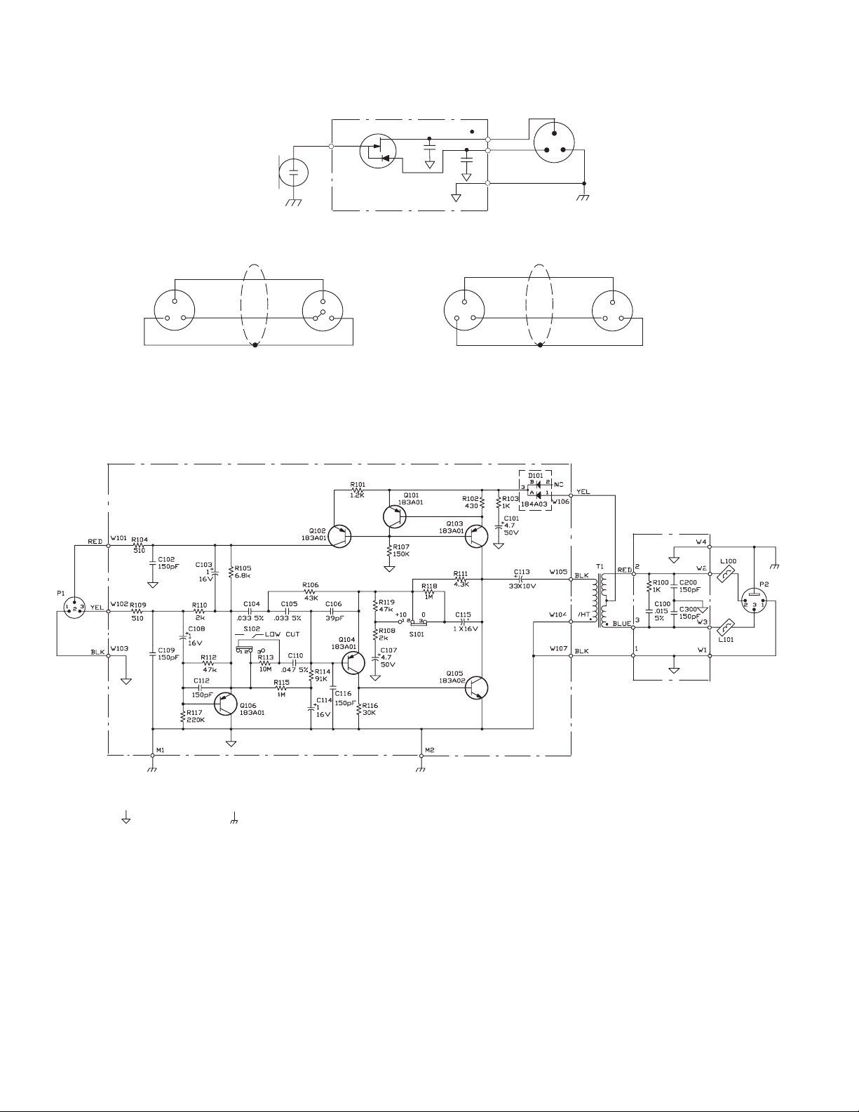
CONDENSER
CARTRIDGE
MK1
IMPEDANCE
CONVERTER
D
G
U1
C1
S
98 MICROPHONE
RED DOT
C2
3–PIN MINIA
CONNECTOR
(TB3M)
RED
BLUE
BLACK
2
31
TURE
2
RED
BLACK
SHIELD
MODEL
WM98 CABLE
RED
2
4
2
BLACK
SHIELD
MODEL
MICROPHONE WIRING DIAGRAMS
FIGURE 12
GAIN
SM98A
33111133
CABLE
2
GRN
OR
BROW
N
OR
NOTES:
1 UNLESS OTHERWISE SPECIFIED, ALL RESISTORS ARE 1/8 WATT
2 UNLESS OTHERWISE SPECIFIED, ALL CAPACITORS IN F, 10%, 50 V OR GREATER. ELECTROLYTIC CAPACITORS SHOWN IN F
3 THE FOLLOWING SYMBOLS DENOTE:
PC BOARD GROUND CHASSIS GROUND
, 5%.
CIRCUIT DIAGRAM – SM98A PREAMPLIFIER
FIGURE 13
5
90B4339C–3
X VOLTS, 20%.
 Loading...