

Shure MICROFLEX MXWANI8, MICROFLEX MXWANI4 User Manual

WIRELESS SYSTEM
MICROFLEX
WIRELESS
AUDIO NETWORK INTERFACE
USER GUIDE
© 2015 Shure Incorporated
27A20456 (Rev. 3)
IMPORTANT SAFETY INSTRUCTIONS
1. READ these instructions.
2. KEEP these instructions.
3. HEED all warnings.
4. FOLLOW all instructions.
5. DO NOT use this apparatus near water.
6. CLEAN ONLY with dry cloth.
7. DO NOT block any ventilation openings. Allow sufficient distances for adequate ventilation and install in accordance with the manufacturer’s instructions.
8. DO NOT install near any heat sources such as open flames, radiators, heat registers,
stoves, or other apparatus (including amplifiers) that produce heat. Do not place any open
flame sources on the product.
9. DO NOT defeat the safety purpose of the polarized or groundingtype plug. A polarized
plug has two blades with one wider than the other. A grounding type plug has two blades
and a third grounding prong. The wider blade or the third prong are provided for your
safety. If the provided plug does not fit into your outlet, consult an electrician for replacement of the obsolete outlet.
10. PROTECT the power cord from being walked on or pinched, particularly at plugs, convenience receptacles, and the point where they exit from the apparatus.
11. ONLY USE attachments/accessories specified by the manufacturer.
12. USE only with a cart, stand, tripod, bracket, or table specified by the manufacturer, or sold with the apparatus. When a cart is used, use caution when
moving the cart/apparatus combination to avoid injury from tip-over.
13. UNPLUG this apparatus during lightning storms or when unused for long
periods of time.
14. REFER all servicing to qualified service personnel. Servicing is required when the apparatus has been damaged in any way, such as power supply cord or plug is damaged,
liquid has been spilled or objects have fallen into the apparatus, the apparatus has been
exposed to rain or moisture, does not operate normally, or has been dropped.
15. DO NOT expose the apparatus to dripping and splashing. DO NOT put objects filled with
liquids, such as vases, on the apparatus.
16. The MAINS plug or an appliance coupler shall remain readily operable.
17. The airborne noise of the Apparatus does not exceed 70dB (A).
18. Apparatus with CLASS I construction shall be connected to a MAINS socket outlet with a
protective earthing connection.
19. To reduce the risk of fire or electric shock, do not expose this apparatus to rain or
moisture.
20. Do not attempt to modify this product. Doing so could result in personal injury and/or
product failure.
21. Operate this product within its specified operating temperature range.
This symbol indicates that dangerous voltage constituting a risk of
electric shock is present within this unit.
This symbol indicates that there are important operating and maintenance instructions in the literature accompanying this unit.
WARNING: This product contains a chemical known to the State of California to cause cancer and birth
defects or other reproductive harm.

General Description
The MXW Audio Network Interface (ANI) is a digital-to-analog breakout box
with a built-in gigabit network switch. It converts digital audio from a network
into analog signals for signal processing or amplification. Input channels add
analog audio to the network and can be routed to MXW microphones as a
translation channel or for personal monitoring.
The front panel includes channel status indicators and controls for gain and
mute adjustment. Monitoring features include a headphone jack and dBFS
output meter. A computer can remotely monitor and control a networked unit
from a built-in webserver interface (GUI).
MICROFLEX WIRELESS
A
INPUT
sig/clip
mute
A
INPUT
sig/clip
mute
1
B
OUTPUT
line
aux
sig/clip
mute
push to solo | hold to mute
5
4
3
2
1
B
OUTPUT
line
aux
sig/clip
mute
push to solo | hold to mute
line
aux
mic
8
7
6
line
aux
mic
power
-9
0
ethernet
-18
-9
network audio
-12
-24
-18
-36
-24
-48
lockout
-60
adjust
0
power
-9
0
ethernet
-18
-9
network audio
-12
-24
-18
-36
-24
-48
lockout
-60
adjust
0
8
7
6
5
4
3
2
HEADPHONE
HEADPHONE
Audio Network Interface
MICROFLEX WIRELESS
Audio Network Interface
Features
• Converts digital audio from the Dante network into analog output signals
• Built-in gigabit network switch with four ports
• Input channels add analog audio to the digital audio network
• Front-panel gain and mute controls
• Headphone jack for monitoring and troubleshooting
• Monitor LEDs display channel status and output levels
Microflex Wireless Series
The ANI is a part of the Microflex Wireless Series (MXW), a complete
solution for meeting room and presentation applications. Developed with
tm
Dante
technology by Audinate, digital audio is routed over standard IP
equipment across a network of access points, digital-to-analog converters
and computers. Access points mount to a ceiling or wall and communicate
wirelessly with the microphones to add audio to the network. RF
coordination is automatic and continuous, offering worry-free wireless audio
transmission for every event.
②
③
④
①
⑤
Model Variations
Model Analog Outputs
(mic/line/aux)
MXWANI8 8 2 4
MXWANI4 4 1 4
MXW Connections
Requirements: Shielded Cat5e network cable (or higher)
①
⑦
2
1
3
5
7
6
4
8
Analog Inputs
(line/aux)
③②
1
2
3
5
7
6
4
8
Gigabit Ports
④
⑤⑥
MXW Components
① Microflex Microphones
The MXW microphones are available in gooseneck, boundary,
handheld and bodypack models.
② Access Point Transceiver (APT)
Sleek and unobtrusive, the APT mounts to a wall or ceiling to provide
direct, line-of-sight wireless connection to the microphones. The APT
automatically manages the RF spectrum, ensuring consistent, stable
audio transport from the microphones to the digital network.
③ Networked Charging Station (NCS)
The charger recharges microphones without battery removal and
networks battery status for remote monitoring. The charger also
initiates the linking of microphones to an APT, enabling wireless audio
transmission.
④ Audio Network Interface (ANI)
The ANI converts digital audio from the network into analog audio to
send to a signal processor or amplifier.
⑤ Control Software
The control software allows comprehensive remote management of
the MXW system. It operates in a web browser when networked to a
computer.
① Power
Connect the power cable from
the ANI to an AC power supply.
Turn on the power switch.
② Audio Outputs
Connect to a signal processor,
amplifier or recording system.
③ Audio Inputs
Connect to a line- or aux-level
analog audio source to add it to
the digital network.
④ Network Port 1 (PoE)
Connect to MXWAPT Access
Point to provide Power over
Ethernet (PoE) and networked
audio and control.
⑤ Network Port 2
Connect to an additional
charger, ANI or computer to
provide networked audio and/or
control.
⑥ Network Port 3
Connect to an additional
charger, ANI or computer to
provide networked audio and/or
control.
⑦ Network Port 4 (Uplink)
Connect to a corporate network
for access to the control
software. (When Port 4 Uplink
mode is enabled, Dante Audio
and Controller data are excluded
from this port.)
3
Audio Network Interface (ANI)
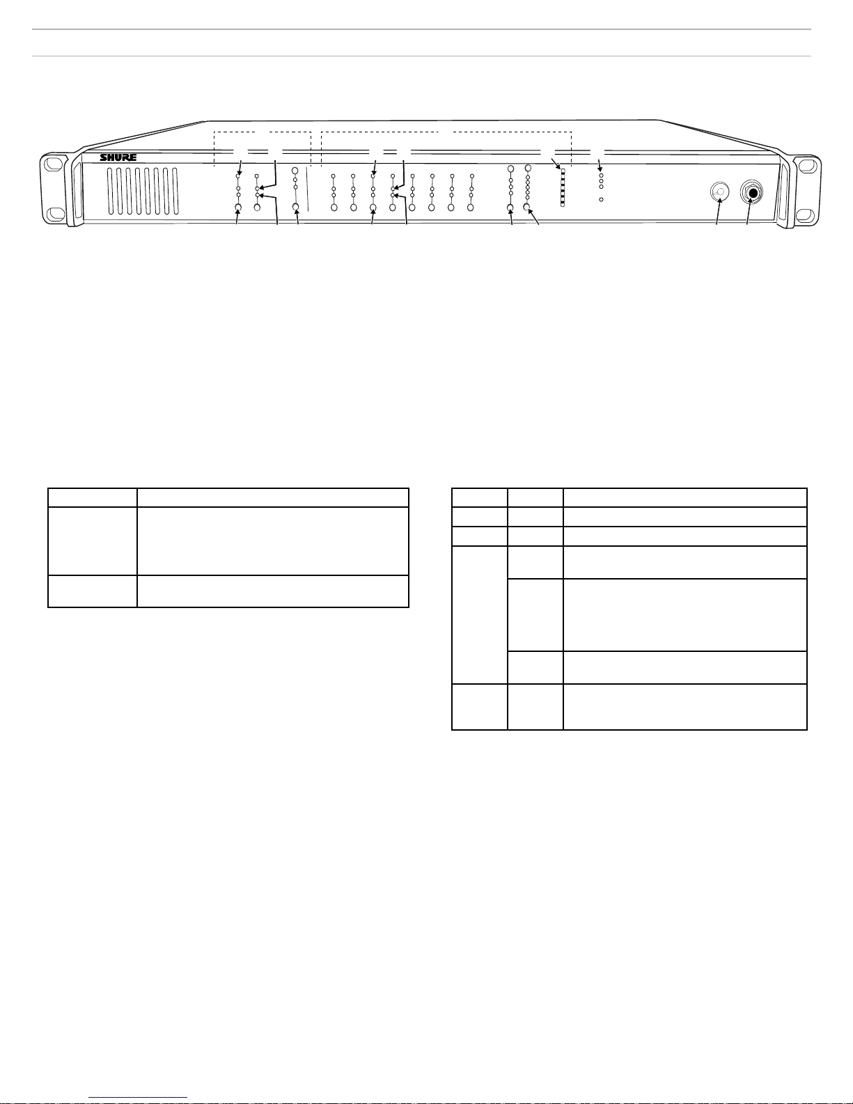
Front Panel
①
⑤ ⑤
④
A
B
INPUT
sig/clip
mute
③
① Input Channels
Adds analog line- or aux-level signals to the digital network. When the
device is associated to an MXW Group, inputs are automatically routed
to Linked microphone channels (Input A to channels 1-4; Input B to 5-8).
② Output Channels
Converts digital network audio to an analog output for each channel.
When associated to an MXW group, access point channels are
automatically routed to the outputs of the ANI.
③ Channel Selector
Selects a channel to perform the following functions:
Action Function
Single Press • Listen to that channel at the headphone jack
• Display and adjust the channel output level and
attenuation
• Monitor output signal on the level meter
Press and Hold
(3 seconds)
④ Selected Channel LED
Illuminates when a channel is selected.
⑤ Signal Strength LED (sig/clip)
Indicates audio signal strength for each channel:
- Green = Normal
- Amber = Strong
- Red = Clipping (to eliminate clipping, attenuate the signal level at the audio
source)
⑥ Mute LED
Illuminates red when the channel output is muted (hold its channel
select button for 3 seconds). A muted channel is still routed to the
HEADPHONE jack for monitoring or troubleshooting.
⑦ Input Level Selector
Set the selected channel to line- or aux-level to match the input signal.
⑧ Output Level Selector
Set the selected channel to an output level that matches the connecting
device:
- line: +4 dBu
- aux: -10 dBV
- mic: -30 dBV
Mute/unmute a channel. Mute is indicated by the
mute LED.
line
aux
⑥ ⑥⑦
OUTPUT
2
1
sig/clip
mute
③
④
4
3
push to solo | hold to mute
②
5
0
line
-9
-12
aux
-18
mic
-24
adjust
8
7
6
⑧ ⑨
⑨ Output Attenuation Control
Use the up/down buttons to attenuate the channel output from 0 dB (no
attenuation) to -24 dB in 1 dB increments, and from -24 to -78 in 3 dB
increments.
⑩ Level Meter
Displays a selected channel's audio level in dBFS. It is good practice to
use -18 dBFS on the output meter as an approximation of 0 VU on an
analog meter.
⑪ Hardware Status LEDs
Indicate the status of the hardware:
LED Color Status
Power Green Unit is powered on.
Ethernet Green Connected to an Ethernet device.
⑩
Network
Audio
Lockout Red Front panel gain and mute controls are locked.
⑫ Headphone Volume Knob
Adjusts the volume to the headphone output.
⑬ Headphone Output
1/4" (6.35 mm) output jack for monitoring audio going to and from the
digital audio network.
Note: Audio is present only when the unit is connected to a digital audio
network.
Green All connected receive channels are OK
Flashing
Green
Off No receive channels connected (routing has
⑪
0
-9
-18
-24
-36
-48
-60
power
ethernet
network audio
lockout
HEADPHONE
MICROFLEX WIRELESS
Audio Network Interface
⑫
(receiving digital audio as expected).
One or more connected receive channels
experiencing a subscription error or is
unresolved (transmitting device is off,
disconnected, renamed or has incorrect
network setting).
not been established).
The LED will blink when a button is pressed
while the hardware is locked.
⑬
4
 Loading...