

Shure Microflex Complete Wireless MXCW, Microflex MXCW Series, MXCWAPT, MXC420, MXCWNCS Complete User Manual
...
MXCW
®
Microflex Complete Wireless
Complete user guide for the MXCW system. Includes installation instructions, specifications, best practices, and troubleshooting.
Version: 8 (2019-E)

Table of Contents
MXCWMicroflex® Complete Wireless 4
General Description 4
Features 4
System Overview 5
Getting Started 5
Set Up the System Access Point (MXCWAPT) 5
Set Up Wireless Conference Units (MXCW640) 6
Perform a Soundcheck 7
Access Point Transceiver (MXCWAPT) 7
LED Status Indicators 10
Access Point Menu 11
Conference Unit (MXCW640) 13
Gooseneck Microphone (MXC416, MXC420, MXC406/
MS) 14
Using the Conference Units 15
Conference Unit Buttons 15
Using the MXCW640 Touchscreen 17
Rechargeable Battery (SB930) 20
Important Tips for Care and Storage of Shure Recharge
able Batteries 20
Networked Charging Station (MXCWNCS) 21
Powering On the Device 22
Monitoring Battery Charge 23
Icons for Charging Batteries 23
Charge Status LEDs 23
Average Charging Times 24
Charging Batteries with USB 24
Battery Statistics 25
Storing Batteries 25
Shure Incorporated
Installation 26
Additional Equipment 26
Requirement Checklist 26
Mount the Access Point Transceiver 27
Mount the Networked Charging Station 36
System Set Up 38
Maximum System Size 38
Wireless Device Network 38
Connecting Devices for the First Time 38
Custom Network SSID Labels 39
Separating Networks for Multiple Systems 40
Conference Unit Startup Mode 42
Web Applications for Monitoring and Control 43
Opening the Device Web Application 43
Web Browser Requirements 44
Using DNS to Open Web Application 45
Web Application Views 45
Wireless and RF Management 47
Wireless Operating Distance 47
Reliable Bandwidth Allocation 49
Selecting or Excluding Specific Wireless Channels 49
Interference Avoidance 49
Interference Avoidance for Regulated Wireless Channels 4
9
Tips to Improve Wireless System Performance 50
Setting the Access Point Country and Region (MX
CWAPT-B and MXCWAPT-W only) 50
Setting Up Participants 51
Participant Roles 51
Changing the Participant Role 51
Identifying a Device from the Software 52
2/101

Shure Incorporated
Customizing the Devices Page 53
Assigning Names and Seat Numbers 54
NFC Card Functionality 55
Speak Priority 55
Active Speaker Interruption 56
Microphone Activation Style 56
Setting the Number of Active Speakers 57
Participant Microphone Control by Admin/Chairman 57
Managing Speakers from the Web Application 58
Audio Setup and Channel Routing 59
MXCW Routing Descriptions 60
MXCW Wireless Audio 61
The Floor Mix 62
Analog Connections 62
Connecting Analog Devices 63
Automatic Gain Control (AGC) 64
Adding Other Sources to the Floor Mix 65
Language Interpretation 69
Headphone Channels 70
Set Up Interpretation Channels 71
Digital Audio Networking 72
Dante Network Audio 72
Switch Recommendations for Dante Networking 72
QoS (Quality of Service) Settings 73
Packet Bridge 73
Networking 74
Networking Best Practices 74
Device IP Settings 74
Configuring IP Settings 74
Manually Assigning Static IP Address 75
Setting Latency 75
Using the Web Application with a Wireless Connection 75
IP Ports and Protocols 76
AES67 77
Security 77
Restricting New Device Connections 78
Saving Device Settings 79
System Maintenance and Troubleshooting 79
Troubleshooting 80
Resetting Devices 80
Additional Troubleshooting Resources 81
Firmware 81
Firmware Updates 81
Update Firmware for Conference Units 81
Firmware Versioning 82
Using a Third-Party Control System 82
Specifications 82
System 82
MXCWAPT 83
MXCW640 86
MXCWNCS 93
SB930 94
Accessories 95
Optional Accessories 95
Access Point Model Variations 95
Networked Charging Station Model Variations 96
Important Product Information 96
Safety Information 96
Information to the user 98
Certifications 99
Trademarks 101
3/101
Shure Incorporated
MXCW
Microflex Complete Wireless
®
General Description
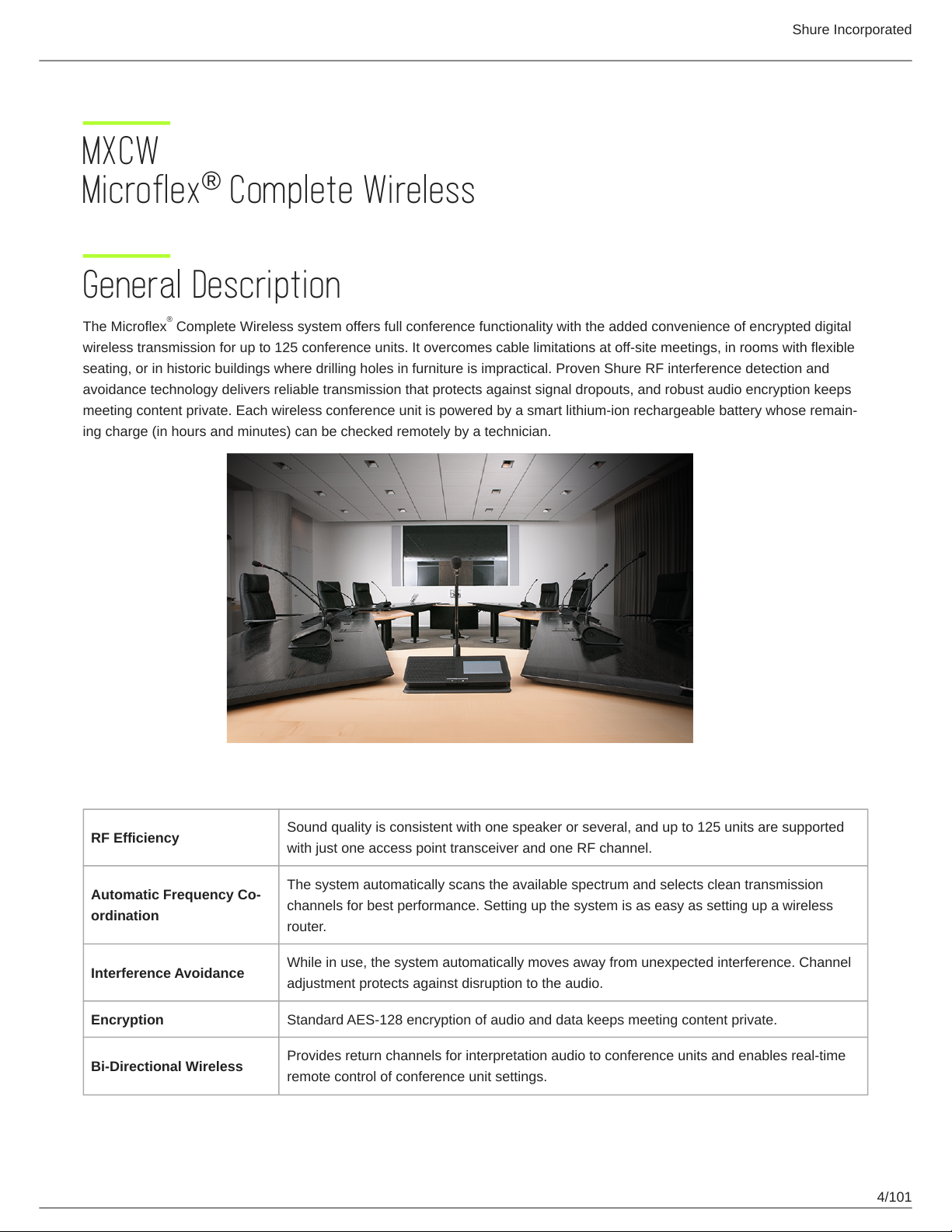
The Microflex Complete Wireless system offers full conference functionality with the added convenience of encrypted digital
wireless transmission for up to 125 conference units. It overcomes cable limitations at off-site meetings, in rooms with flexible
seating, or in historic buildings where drilling holes in furniture is impractical. Proven Shure RF interference detection and
avoidance technology delivers reliable transmission that protects against signal dropouts, and robust audio encryption keeps
meeting content private. Each wireless conference unit is powered by a smart lithiumion rechargeable battery whose remain
ing charge (in hours and minutes) can be checked remotely by a technician.
®
Features
RF Efficiency
Automatic Frequency Co
ordination
Interference Avoidance
Encryption Standard AES-128 encryption of audio and data keeps meeting content private.
Bi-Directional Wireless
Sound quality is consistent with one speaker or several, and up to 125 units are supported
with just one access point transceiver and one RF channel.
The system automatically scans the available spectrum and selects clean transmission
channels for best performance. Setting up the system is as easy as setting up a wireless
router.
While in use, the system automatically moves away from unexpected interference. Channel
adjustment protects against disruption to the audio.
Provides return channels for interpretation audio to conference units and enables real-time
remote control of conference unit settings.
4/101
Shure Incorporated
System Overview
The Shure Microflex Complete Wireless (MXCW) system provides a steady, reliable audio experience for off-site meetings,
flexible meeting rooms, or historic buildings. The system features automatic RF interference detection and avoidance,
rechargeable batteries for wireless conference units, encrypted digital wireless transmission, and digital audio networking using
™
Dante .
The MXCW access point has multiple mounting options for discreet communication between wireless conference units and the
digital audio network. The access point works within the 2.4 GHz and 5 GHz frequency bands to support up to 125 conference
units. Conference units have configurable roles for meeting participants, and can be routed to the floor audio or an interpreta
tion channel. The MXCW networked charging station charges and stores up to 10 Shure rechargeable batteries that can be
monitored through its own web application. Use the access point web application for system setup, and to monitor and control
conference units.
®
Getting Started
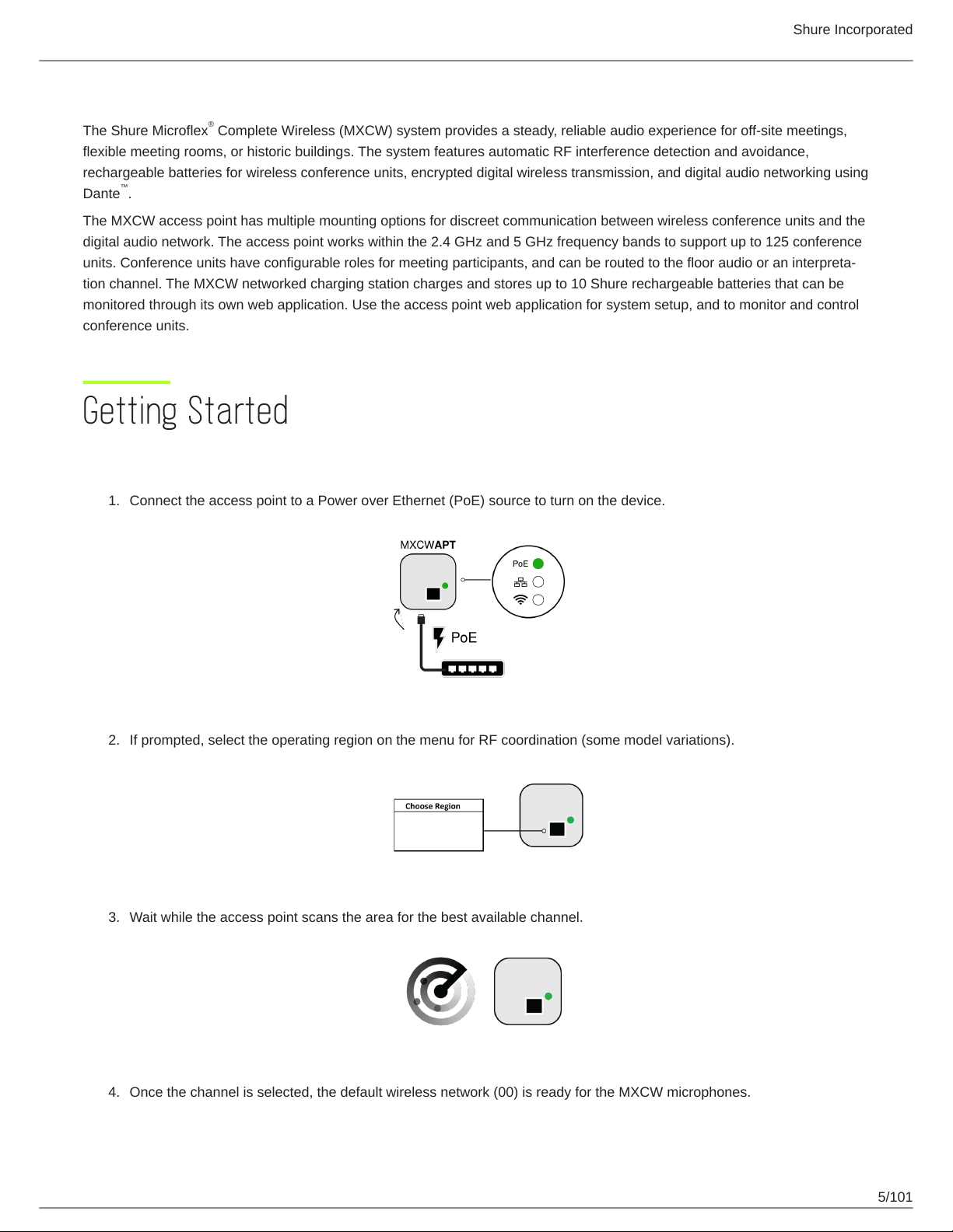
Set Up the System Access Point (MXCWAPT)
1.
Connect the access point to a Power over Ethernet (PoE) source to turn on the device.
2.
If prompted, select the operating region on the menu for RF coordination (some model variations).
3.
Wait while the access point scans the area for the best available channel.
4.
Once the channel is selected, the default wireless network (00) is ready for the MXCW microphones.
5/101
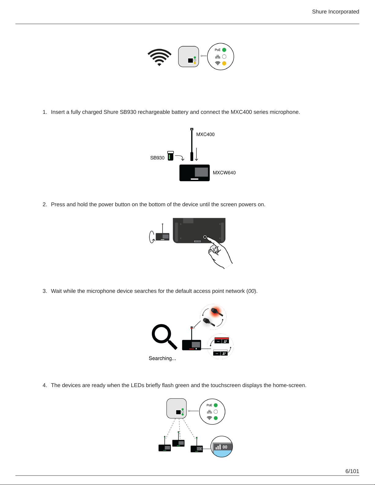
Set Up Wireless Conference Units (MXCW640)
1.
Insert a fully charged Shure SB930 rechargeable battery and connect the MXC400 series microphone.
Shure Incorporated
2.
Press and hold the power button on the bottom of the device until the screen powers on.
3.
Wait while the microphone device searches for the default access point network (00).
4.
The devices are ready when the LEDs briefly flash green and the touchscreen displays the home-screen.
6/101
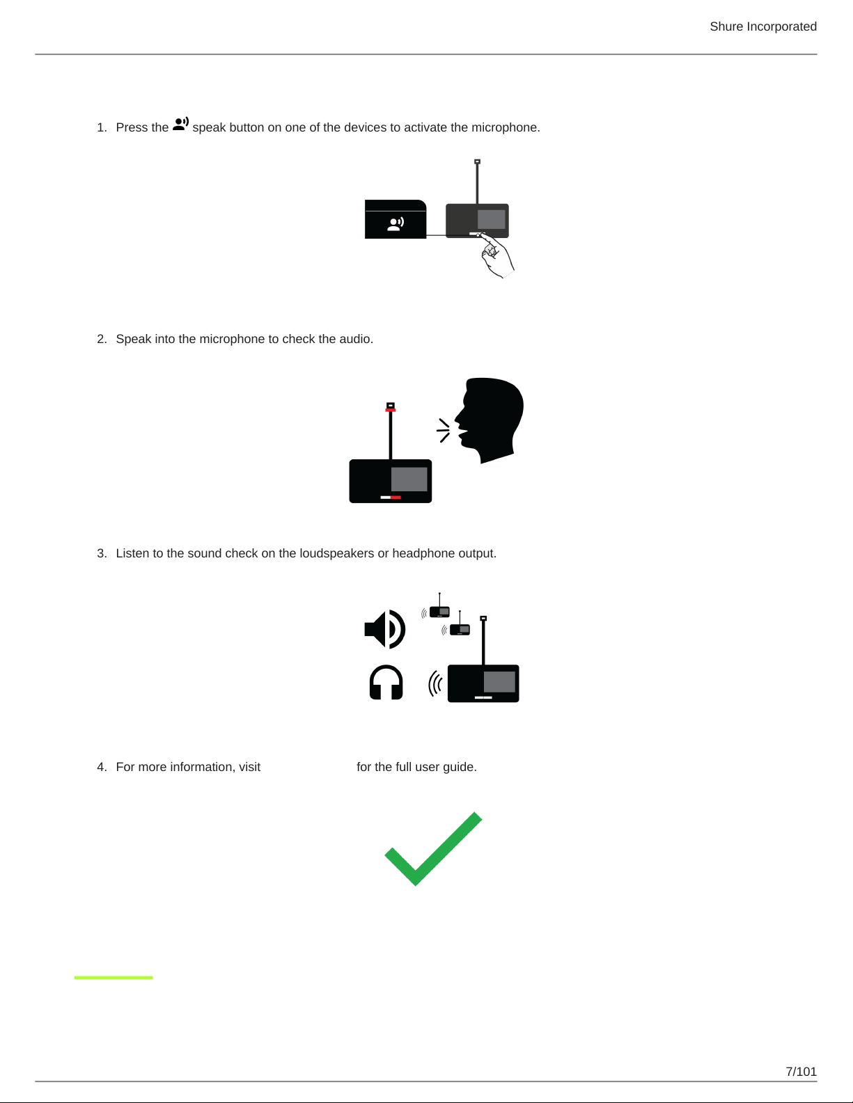
Perform a Soundcheck
1.
Press the speak button on one of the devices to activate the microphone.
2.
Speak into the microphone to check the audio.
Shure Incorporated
3.
Listen to the sound check on the loudspeakers or headphone output.
4.
For more information, visit pubs.shure.com for the full user guide.
7/101
Shure Incorporated
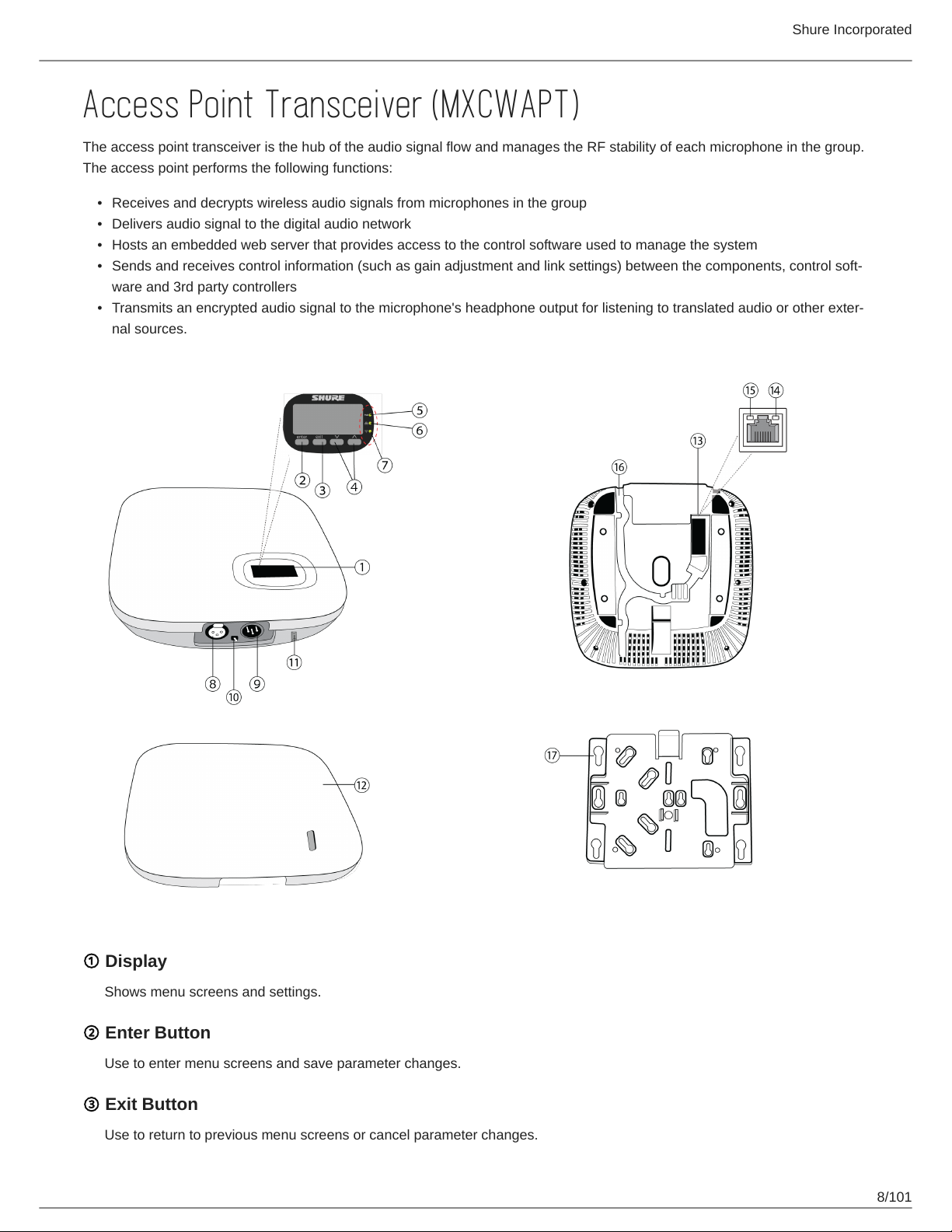
Access Point Transceiver (MXCWAPT)
The access point transceiver is the hub of the audio signal flow and manages the RF stability of each microphone in the group.
The access point performs the following functions:
•
Receives and decrypts wireless audio signals from microphones in the group
•
Delivers audio signal to the digital audio network
•
Hosts an embedded web server that provides access to the control software used to manage the system
•
Sends and receives control information (such as gain adjustment and link settings) between the components, control soft
ware and 3rd party controllers
•
Transmits an encrypted audio signal to the microphone's headphone output for listening to translated audio or other exter
nal sources.
① Display
Shows menu screens and settings.
② Enter Button
Use to enter menu screens and save parameter changes.
③ Exit Button
Use to return to previous menu screens or cancel parameter changes.
8/101
④ Arrow Buttons
Use to scroll through menu screens and change menu parameters.
⑤ Power LED
Illuminates green to indicate the presence of Power over Ethernet (PoE).
⑥ Network Audio LED
Indicates status of connected Dante network audio channels.
⑦ Wireless Audio LED
Indicates status or wireless connection.
⑧ Analog XLR Audio Input
Connect an external output.
⑨ Analog XLR Audio Output
Shure Incorporated
Connect to an external input.
⑩ Ground Lift Switch
Lifts the ground from pin 1 of the XLR connector and the sleeve of the ¼" Audio Output to minimize ground-related noise
that can occur when connecting the XLR Audio Output or Input to a thirdparty device. The ON position of the switch is la
beled lift.
⑪ Reset Button (recessed)
Press and hold the reset button for 10 seconds to reset the MXCW system to factory default settings.
⑫ Access Point Cover
Paint to match the surrounding decor and snap onto the front plate of the device.
The LCD menu and navigation buttons are inaccessible with the cover.
⑬ Ethernet Port
Connect a Cat5e (or higher) cable to a PoE source and the network.
⑭ Ethernet Status LED (Green)
◦
Off = no network link
◦
On = network link established
◦
Flashing = network link active
⑮ Ethernet Link Speed LED (Amber)
◦
Off = 10/100 Mbps
◦
On = 1 Gbps (required for digital audio routing)
⑯ Cable Routing Path
Provides a path for the Ethernet cable to enable a flush-mount.
9/101
⑰ Mounting Bracket
Allows for optional mounting to a wall, ceiling, or mic stand.
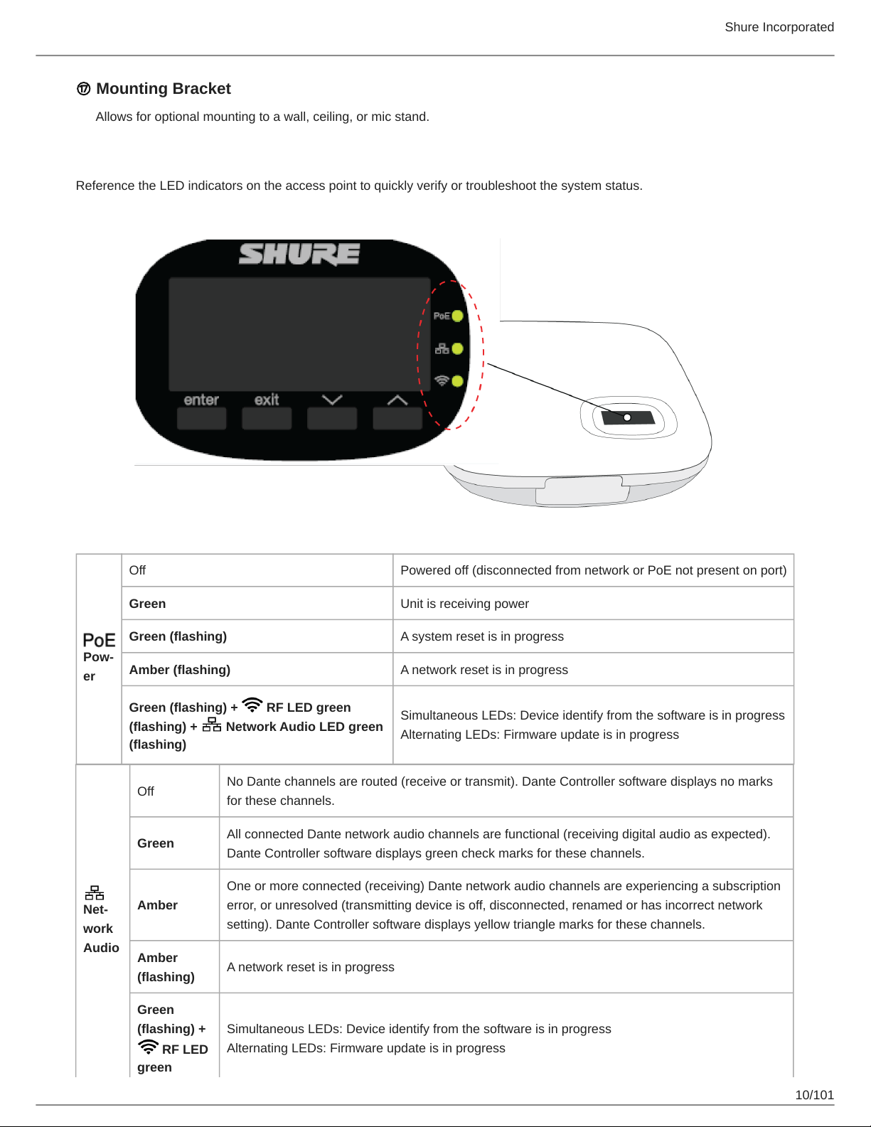
LED Status Indicators
Reference the LED indicators on the access point to quickly verify or troubleshoot the system status.
Shure Incorporated
Pow
er
Net
work
Audio
Off Powered off (disconnected from network or PoE not present on port)
Green Unit is receiving power
Green (flashing) A system reset is in progress
Amber (flashing) A network reset is in progress
Green (flashing) + RF LED green
(flashing) + Network Audio LED green
(flashing)
Off
Green
Amber
Amber
(flashing)
No Dante channels are routed (receive or transmit). Dante Controller software displays no marks
for these channels.
All connected Dante network audio channels are functional (receiving digital audio as expected).
Dante Controller software displays green check marks for these channels.
One or more connected (receiving) Dante network audio channels are experiencing a subscription
error, or unresolved (transmitting device is off, disconnected, renamed or has incorrect network
setting). Dante Controller software displays yellow triangle marks for these channels.
A network reset is in progress
Simultaneous LEDs: Device identify from the software is in progress
Alternating LEDs: Firmware update is in progress
Green
(flashing) +
RF LED
green
Simultaneous LEDs: Device identify from the software is in progress
Alternating LEDs: Firmware update is in progress
10/101
(flashing) +
Power
LED green
(flashing)
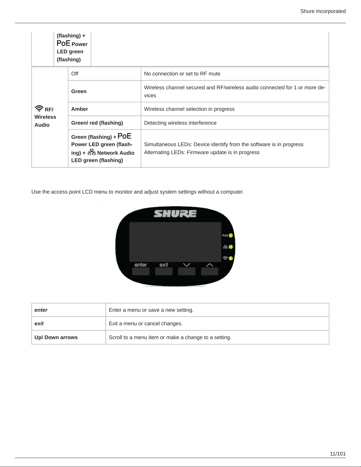
Off No connection or set to RF mute
Shure Incorporated
Wireless channel secured and RF/wireless audio connected for 1 or more de
vices
Simultaneous LEDs: Device identify from the software is in progress
Alternating LEDs: Firmware update is in progress
RF/
Wireless
Audio
Green
Amber Wireless channel selection in progress
Green/ red (flashing) Detecting wireless interference
Green (flashing) +
Power LED green (flash
ing) + Network Audio
LED green (flashing)
Access Point Menu
Use the access point LCD menu to monitor and adjust system settings without a computer.
enter Enter a menu or save a new setting.
exit Exit a menu or cancel changes.
Up/ Down arrows Scroll to a menu item or make a change to a setting.
11/101
Shure Incorporated
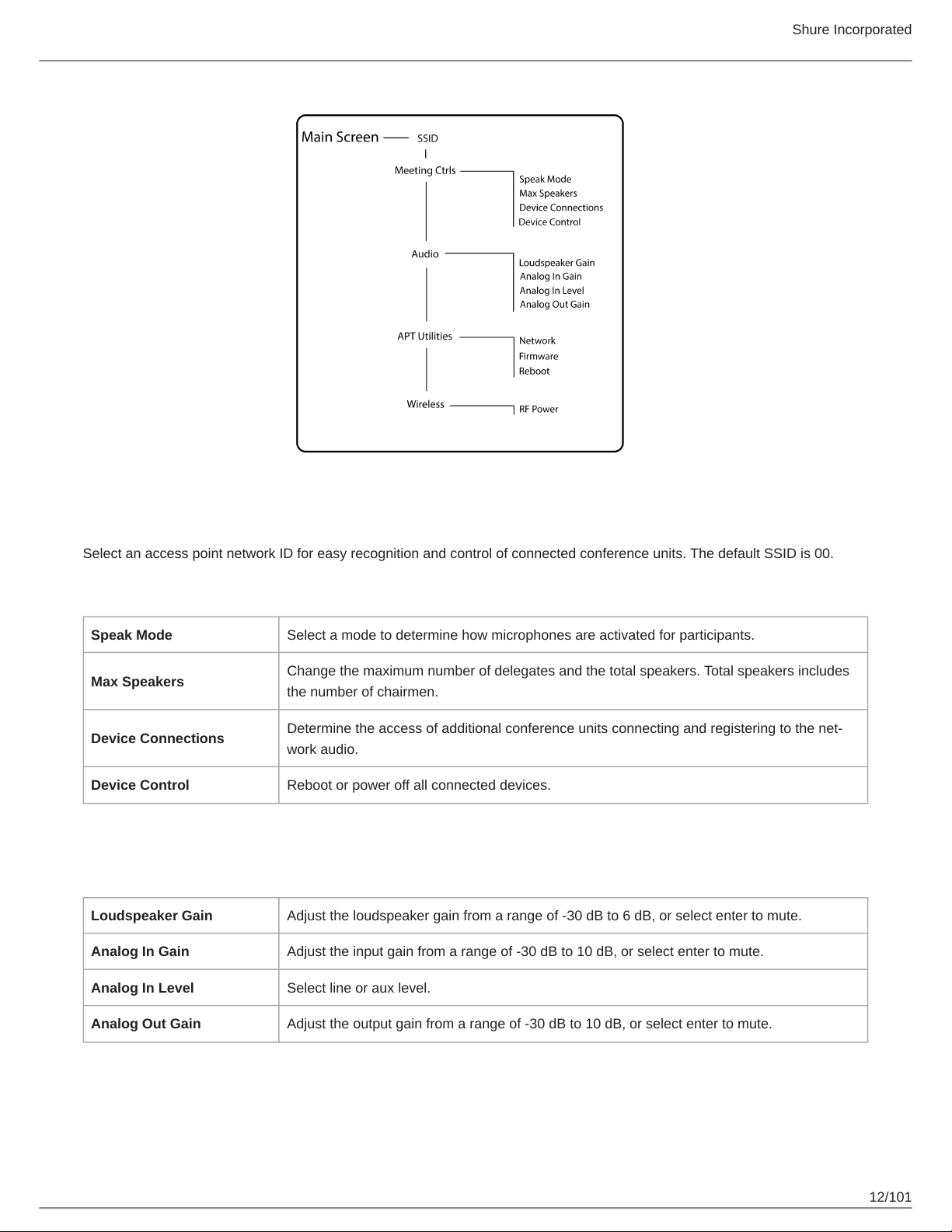
SSID Menu
Select an access point network ID for easy recognition and control of connected conference units. The default SSID is 00.
Meeting Ctrls Menu
Speak Mode Select a mode to determine how microphones are activated for participants.
Max Speakers
Device Connections
Device Control Reboot or power off all connected devices.
Change the maximum number of delegates and the total speakers. Total speakers includes
the number of chairmen.
Determine the access of additional conference units connecting and registering to the net
work audio.
Audio Menu
Loudspeaker Gain Adjust the loudspeaker gain from a range of -30 dB to 6 dB, or select enter to mute.
Analog In Gain Adjust the input gain from a range of -30 dB to 10 dB, or select enter to mute.
Analog In Level Select line or aux level.
Analog Out Gain Adjust the output gain from a range of -30 dB to 10 dB, or select enter to mute.
12/101
APT Utilities Menu
Shure Control displays the IP address, Subnet, Gateway, and MAC address of the access
Network
Firmware Display the access point firmware version and serial number.
Reboot The unit performs a power cycle.
point, while Audio Network shows this information for Dante. Set the IP address for each net
work interface to automatic for an assigned IP address, or manual to edit the IP address.
Wireless Menu
RF Power Select the RF coverage level of the access point, or turn it off.
Shure Incorporated
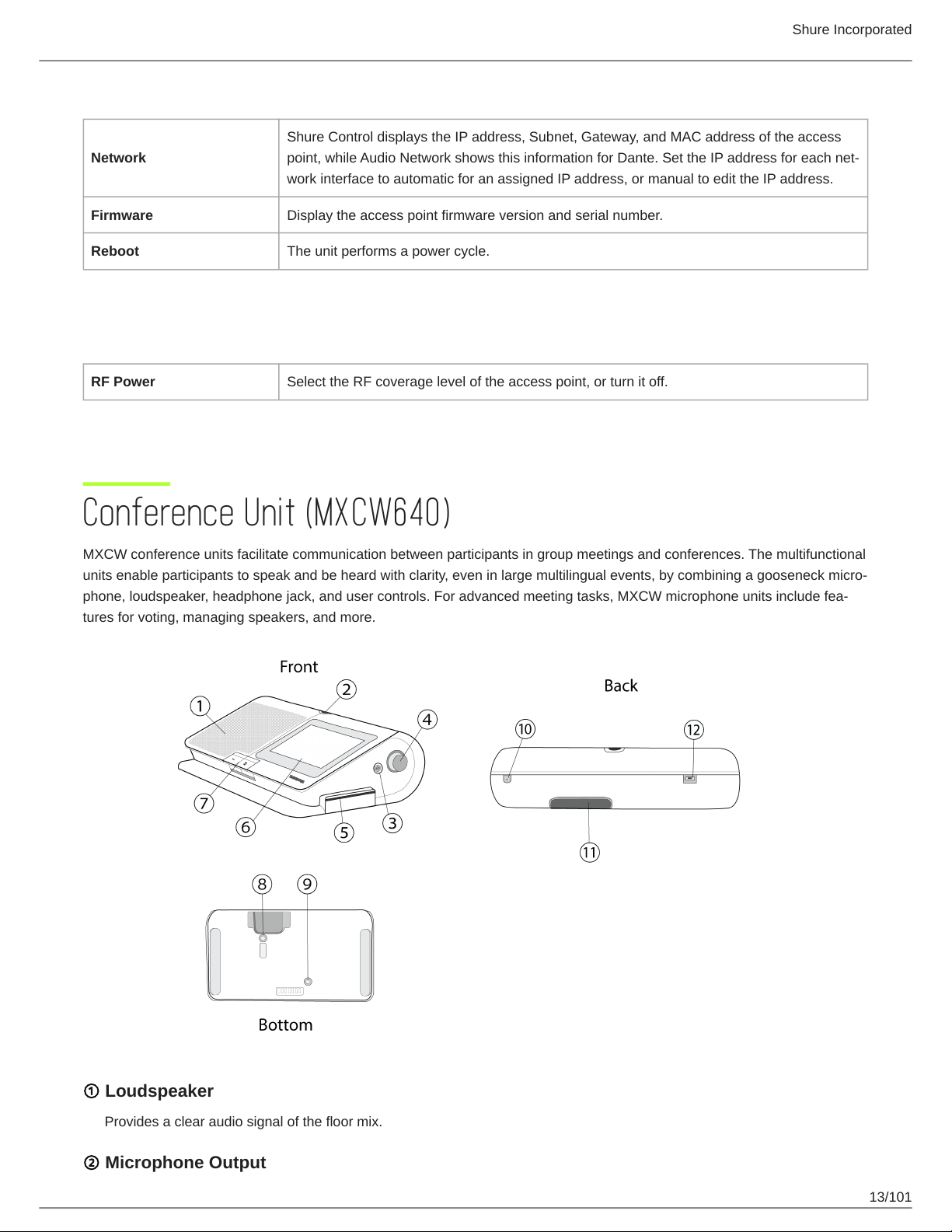
Conference Unit (MXCW640)
MXCW conference units facilitate communication between participants in group meetings and conferences. The multifunctional
units enable participants to speak and be heard with clarity, even in large multilingual events, by combining a gooseneck micro
phone, loudspeaker, headphone jack, and user controls. For advanced meeting tasks, MXCW microphone units include fea
tures for voting, managing speakers, and more.
① Loudspeaker
Provides a clear audio signal of the floor mix.
② Microphone Output
13/101
Shure Incorporated
Lockable 10-pin microphone connector for MXC gooseneck microphones.
③ Headphone Output
Two TRRS 3.5 mm ports on each side of the unit allow participants to listen to an interpretation channel or the floor audio
over headphones.
④ Volume Control
Two knobs on each side increase and decrease audio playback volume for headphones.
⑤ NFC Card Slot
Insert an NFC card to provide participant identification.
⑥ Touchscreen
View and select menu options on the display.
⑦ Microphone Buttons
Press to control the microphone. The buttons are customizable and function differently depending on the participant role
and meeting setup. See Using the Conference Units for more details.
⑧ Power Button
Press and hold to power the unit on or off. The button LEDs on the front of the unit light up red when it is powered on.
⑨ Battery Status Button
Press to check the remaining charge of the battery in the unit.
⑩ TRRS Port
Enables a remote caller to listen and be heard over the floor mix when a cell phone is connected.
⑪ Battery Slot
Insert an SB930 rechargeable battery to power on the unit.
⑫ USB Micro-B Connector
Connect a USB Micro-B cable to charge the battery in the conference unit.
Gooseneck Microphone (MXC416, MXC420, MXC406/MS)
The MXCW microphone delivers excellent audio performance with a frequency response specifically tailored for speech. There
are single and dualflex gooseneck options, providing flexible positioning. The gooseneck microphone also contains the follow
ing features:
•
Commshield Technology eliminates RF noise
•
Locking 10-pin modular connector
•
Built-in LED status indicator (LED ring)
•
Compatible with the Microflex series cardioid, supercardioid, and omnidirectional cartridges
•
Available in 15.75 in (40 cm) and 19.69 in (50 cm) lengths, as well as the MXC406/MS mini-shotgun microphone
®
14/101
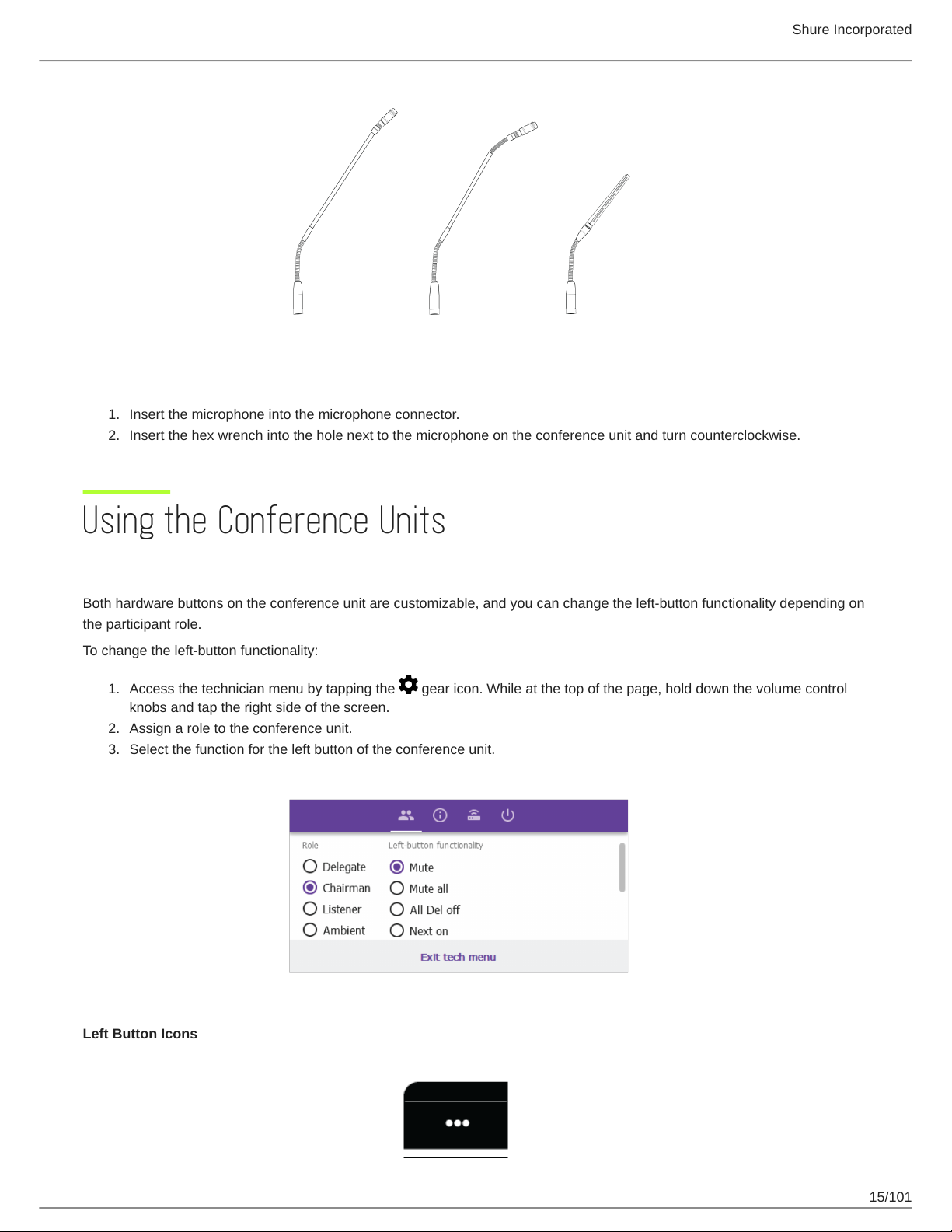
Securing the Microphone to the Conference Unit
1.
Insert the microphone into the microphone connector.
2.
Insert the hex wrench into the hole next to the microphone on the conference unit and turn counterclockwise.
Shure Incorporated
Using the Conference Units
Conference Unit Buttons
Both hardware buttons on the conference unit are customizable, and you can change the left-button functionality depending on
the participant role.
To change the left-button functionality:
1.
Access the technician menu by tapping the gear icon. While at the top of the page, hold down the volume control
knobs and tap the right side of the screen.
2.
Assign a role to the conference unit.
3.
Select the function for the left button of the conference unit.
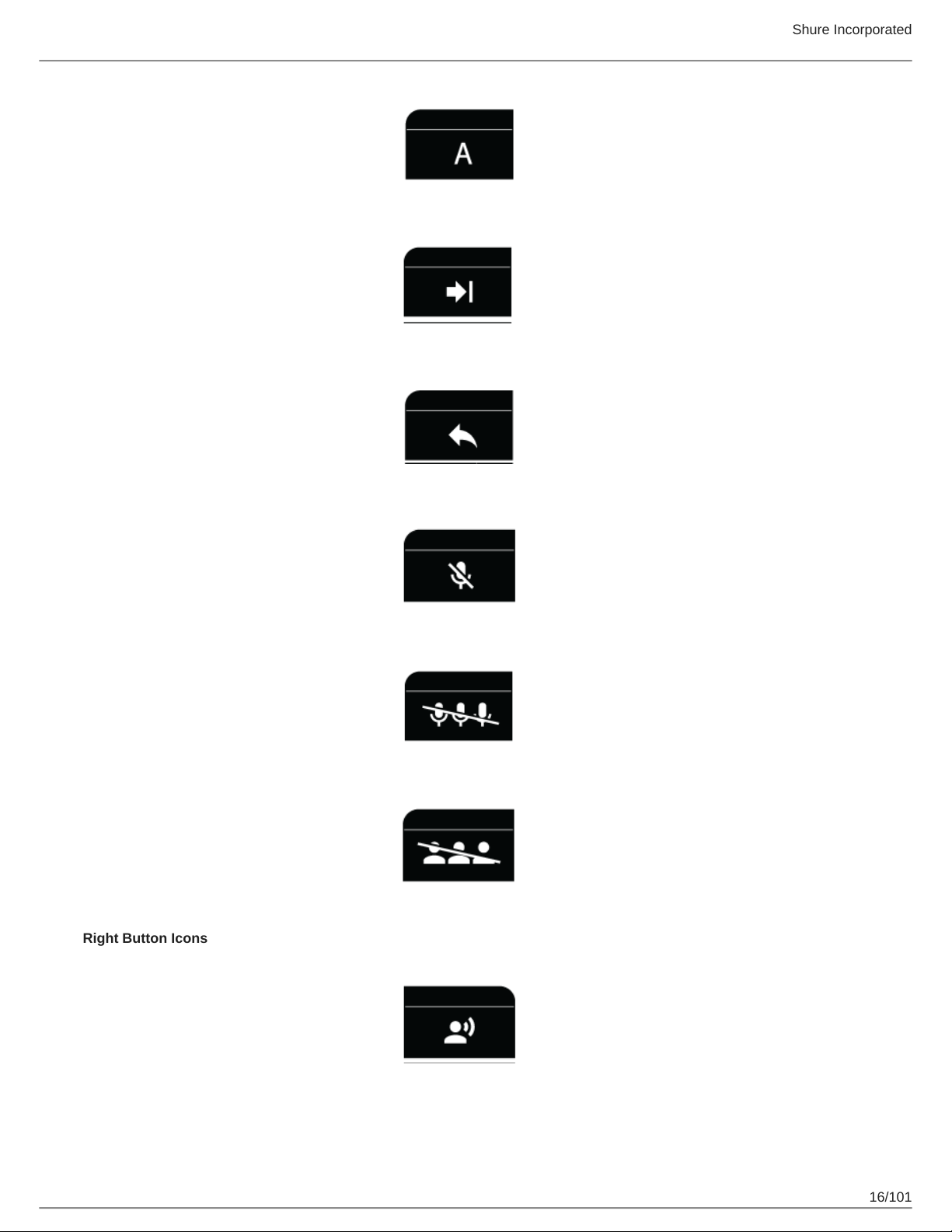
Left Button Icons
15/101
Shure Incorporated
Right Button Icons
16/101
RightBut
ton Func
tionality
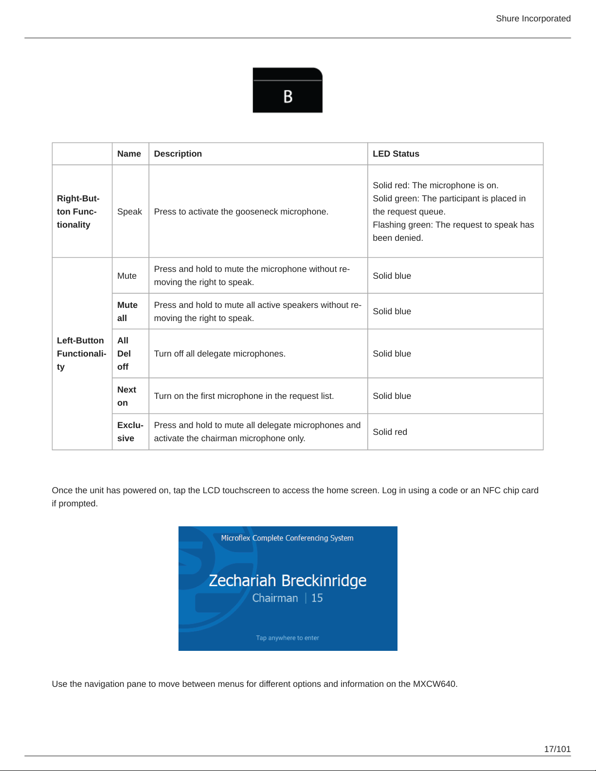
Name Description LED Status
Solid red: The microphone is on.
Solid green: The participant is placed in
Speak Press to activate the gooseneck microphone.
the request queue.
Flashing green: The request to speak has
been denied.
Shure Incorporated
Press and hold to mute the microphone without re
moving the right to speak.
Press and hold to mute all active speakers without re
moving the right to speak.
Turn off all delegate microphones. Solid blue
Turn on the first microphone in the request list. Solid blue
Press and hold to mute all delegate microphones and
activate the chairman microphone only.
Solid blue
Solid blue
Solid red
Left-Button
Functionali
ty
Mute
Mute
all
All
Del
off
Next
on
Exclu
sive
Using the MXCW640 Touchscreen
Once the unit has powered on, tap the LCD touchscreen to access the home screen. Log in using a code or an NFC chip card
if prompted.
Use the navigation pane to move between menus for different options and information on the MXCW640.
17/101
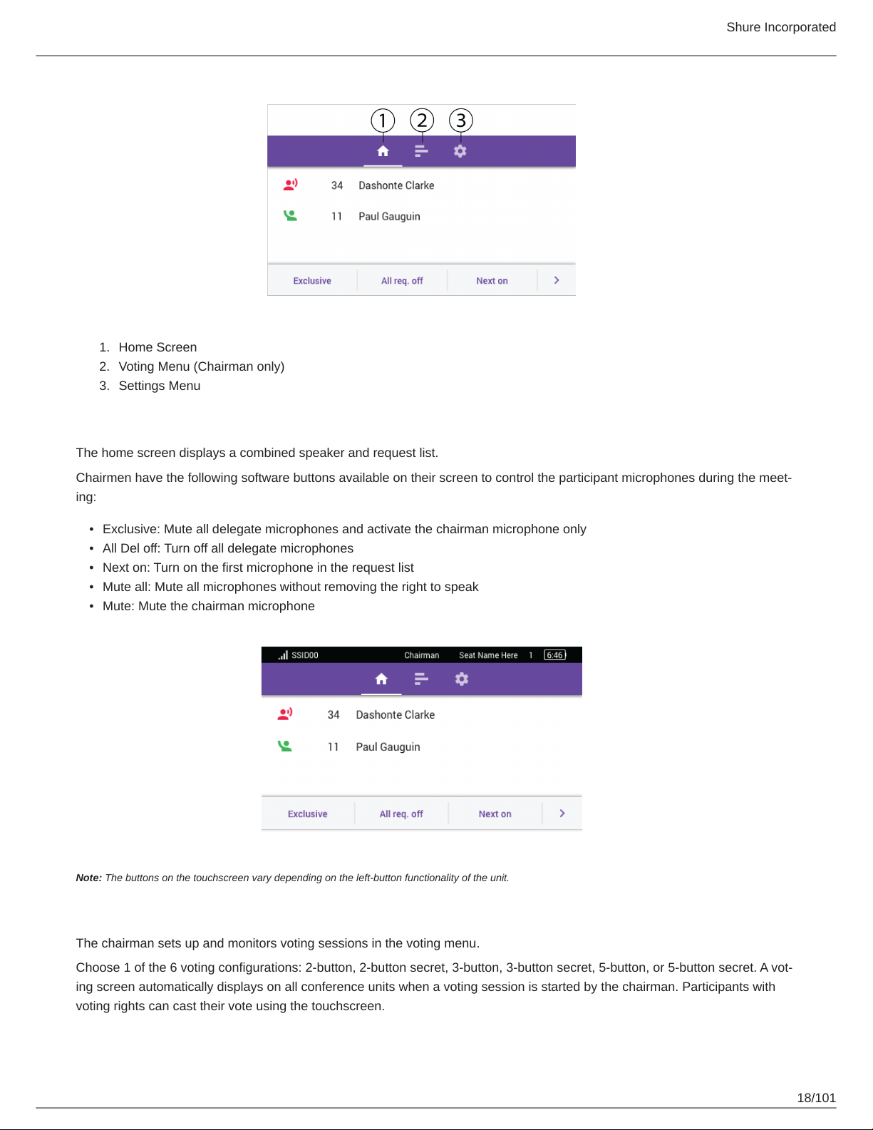
1.
Home Screen
2.
Voting Menu (Chairman only)
3.
Settings Menu
Home Screen
The home screen displays a combined speaker and request list.
Shure Incorporated
Chairmen have the following software buttons available on their screen to control the participant microphones during the meet
ing:
•
Exclusive: Mute all delegate microphones and activate the chairman microphone only
•
All Del off: Turn off all delegate microphones
•
Next on: Turn on the first microphone in the request list
•
Mute all: Mute all microphones without removing the right to speak
•
Mute: Mute the chairman microphone
Note: The buttons on the touchscreen vary depending on the left-button functionality of the unit.
Voting Menu
The chairman sets up and monitors voting sessions in the voting menu.
Choose 1 of the 6 voting configurations: 2button, 2button secret, 3button, 3button secret, 5button, or 5button secret. A vot
ing screen automatically displays on all conference units when a voting session is started by the chairman. Participants with
voting rights can cast their vote using the touchscreen.
18/101
Shure Incorporated
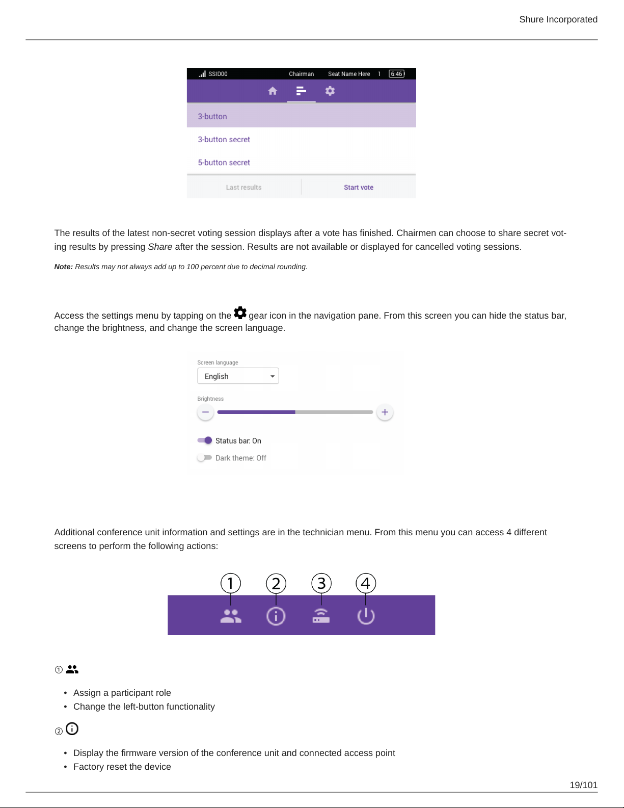
The results of the latest nonsecret voting session displays after a vote has finished. Chairmen can choose to share secret vot
ing results by pressing Share after the session. Results are not available or displayed for cancelled voting sessions.
Note: Results may not always add up to 100 percent due to decimal rounding.
Settings Menu
Access the settings menu by tapping on the gear icon in the navigation pane. From this screen you can hide the status bar,
change the brightness, and change the screen language.
Technician Menu
Additional conference unit information and settings are in the technician menu. From this menu you can access 4 different
screens to perform the following actions:
①
•
Assign a participant role
•
Change the left-button functionality
②
•
Display the firmware version of the conference unit and connected access point
•
Factory reset the device
19/101
•
Reboot the device
③
•
Display the connected access point SSID
•
Disconnect from the access point
④
•
Change the startup mode
•
Power off the device
To access the technician menu:
1.
Tap the gear icon to enter the settings menu.
2.
While at the top of the settings page, hold down on both volume control knobs and tap on the right side of the touch
screen.
Shure Incorporated
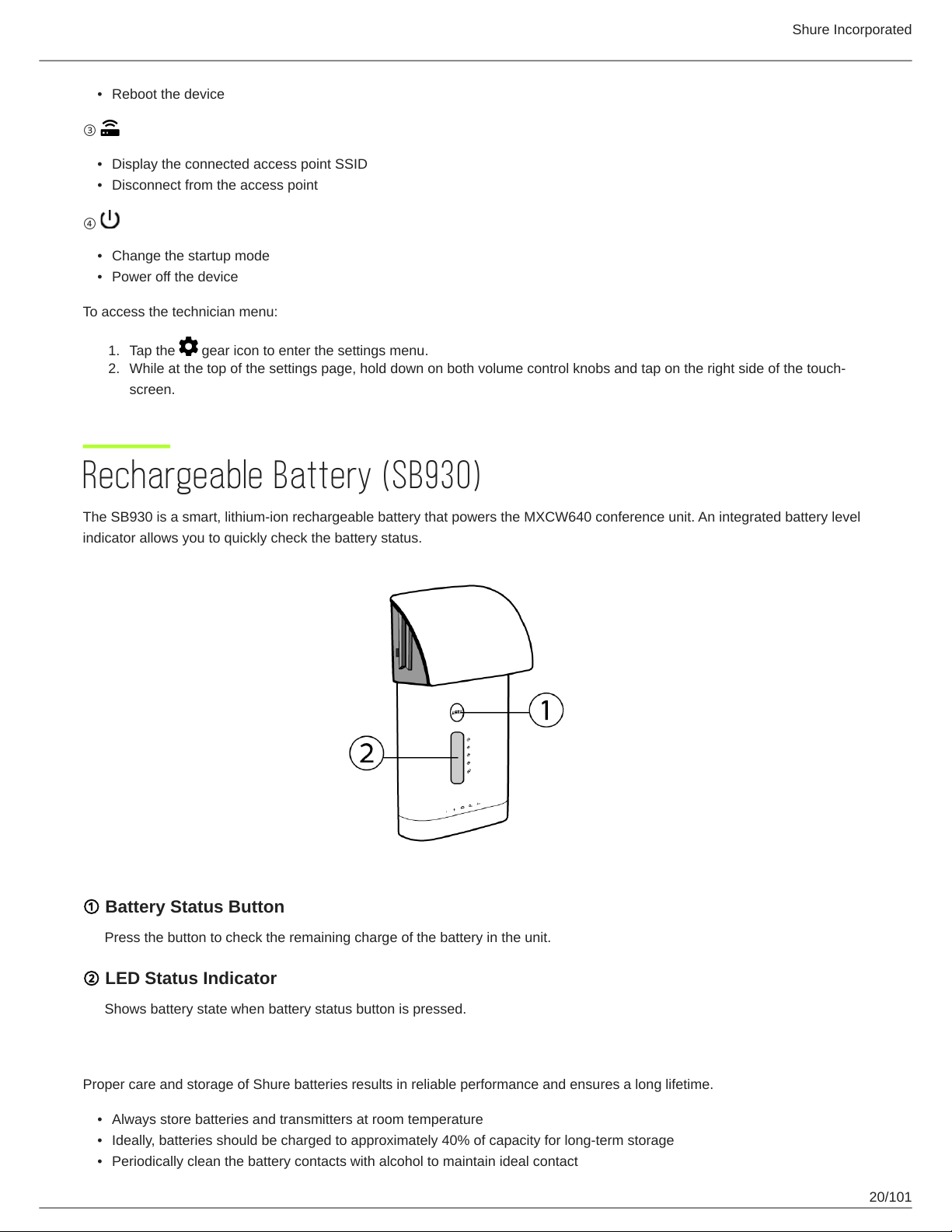
Rechargeable Battery (SB930)
The SB930 is a smart, lithium-ion rechargeable battery that powers the MXCW640 conference unit. An integrated battery level
indicator allows you to quickly check the battery status.
① Battery Status Button
Press the button to check the remaining charge of the battery in the unit.
② LED Status Indicator
Shows battery state when battery status button is pressed.
Important Tips for Care and Storage of Shure Rechargeable Batteries
Proper care and storage of Shure batteries results in reliable performance and ensures a long lifetime.
•
Always store batteries and transmitters at room temperature
•
Ideally, batteries should be charged to approximately 40% of capacity for long-term storage
•
Periodically clean the battery contacts with alcohol to maintain ideal contact
20/101
Shure Incorporated
• During storage, check batteries every 6 months and recharge to 40% of capacity as needed
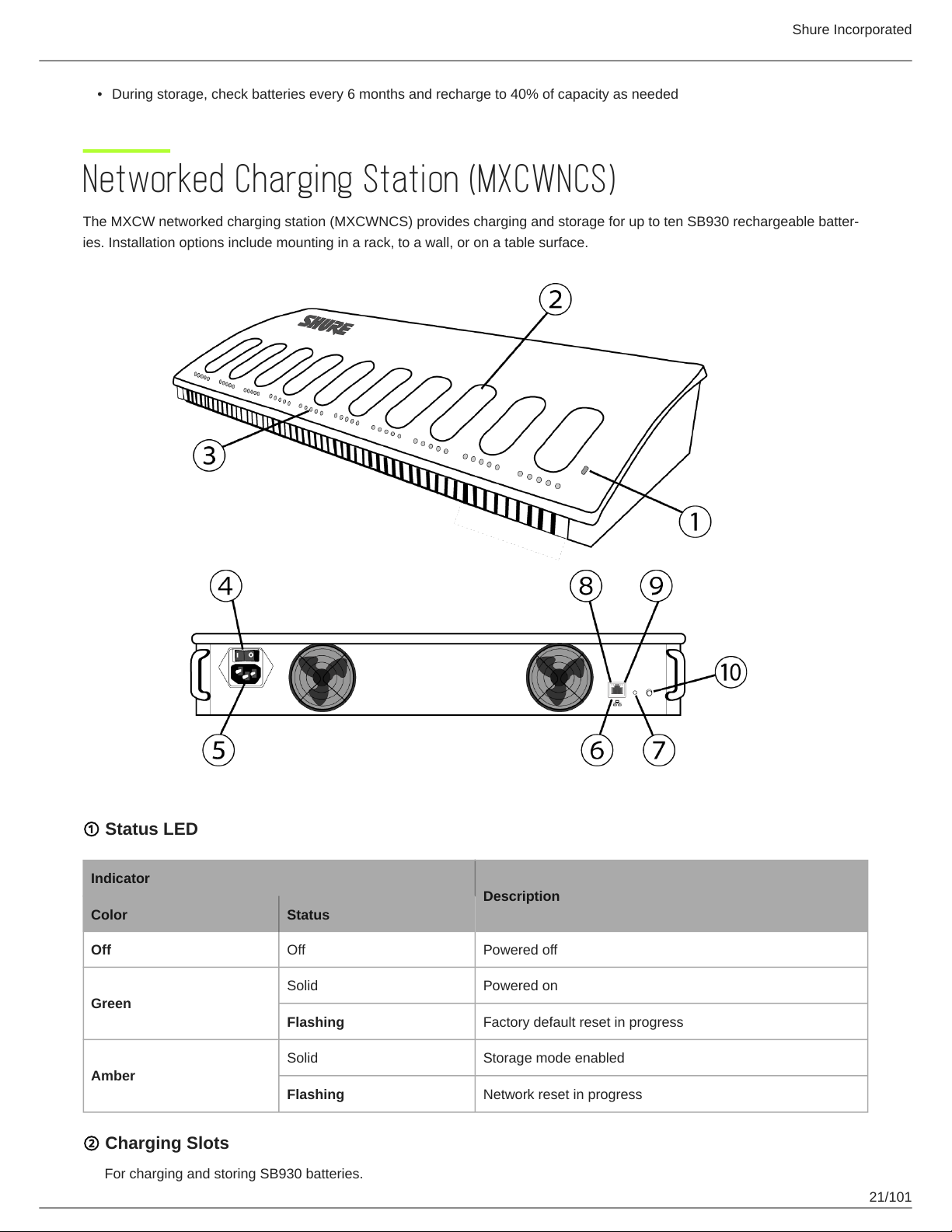
Networked Charging Station (MXCWNCS)
The MXCW networked charging station (MXCWNCS) provides charging and storage for up to ten SB930 rechargeable batter
ies. Installation options include mounting in a rack, to a wall, or on a table surface.
① Status LED
Indicator
Description
Color Status
Off Off Powered off
Solid Powered on
Green
Flashing Factory default reset in progress
Solid Storage mode enabled
Amber
Flashing Network reset in progress
② Charging Slots
For charging and storing SB930 batteries.
21/101
③ Charging Status LEDs
Each charging slot has 5 LEDs that illuminate to show the battery's charge level:
LED % Battery Charge
Shure Incorporated
1
2 >25%
3 >50%
4 >75%
5 >95%
Charging error details are available in the web application and the full online system guide at pubs.shure.com
Flashing: <10%
Solid: >10%
④ Power Button
Flip the switch to turn the unit on or off.
⑤ Power Input
Connect to the included power supply.
⑥ Ethernet Port
Connect to an Ethernet network to enable remote monitoring from the web application.
⑦ Reset Button
Press and hold to reset the device to default settings. The length of the button press determines the type of reset:
◦
Network reset: Press and hold for 4 seconds to reset any network settings and refresh the network connection.
◦
Factory default settings: Press and hold for 8 seconds to reset the device to factory default settings.
⑧ Ethernet Link Speed LED (Amber)
◦
Off = 10 Mbps
◦
On = 100 Mbps
⑨ Ethernet Status LED (Green)
◦
Off = No network link
◦
On = Network link established
◦
Flashing = Network link active
⑩ Storage Mode Button
Press to preserve battery health for batteries being stored for an extended period of time.
Powering On the Device
1.
Connect the device to a power source using the supplied power cable.
22/101
Shure Incorporated
2.
Flip the power switch to turn on the device.
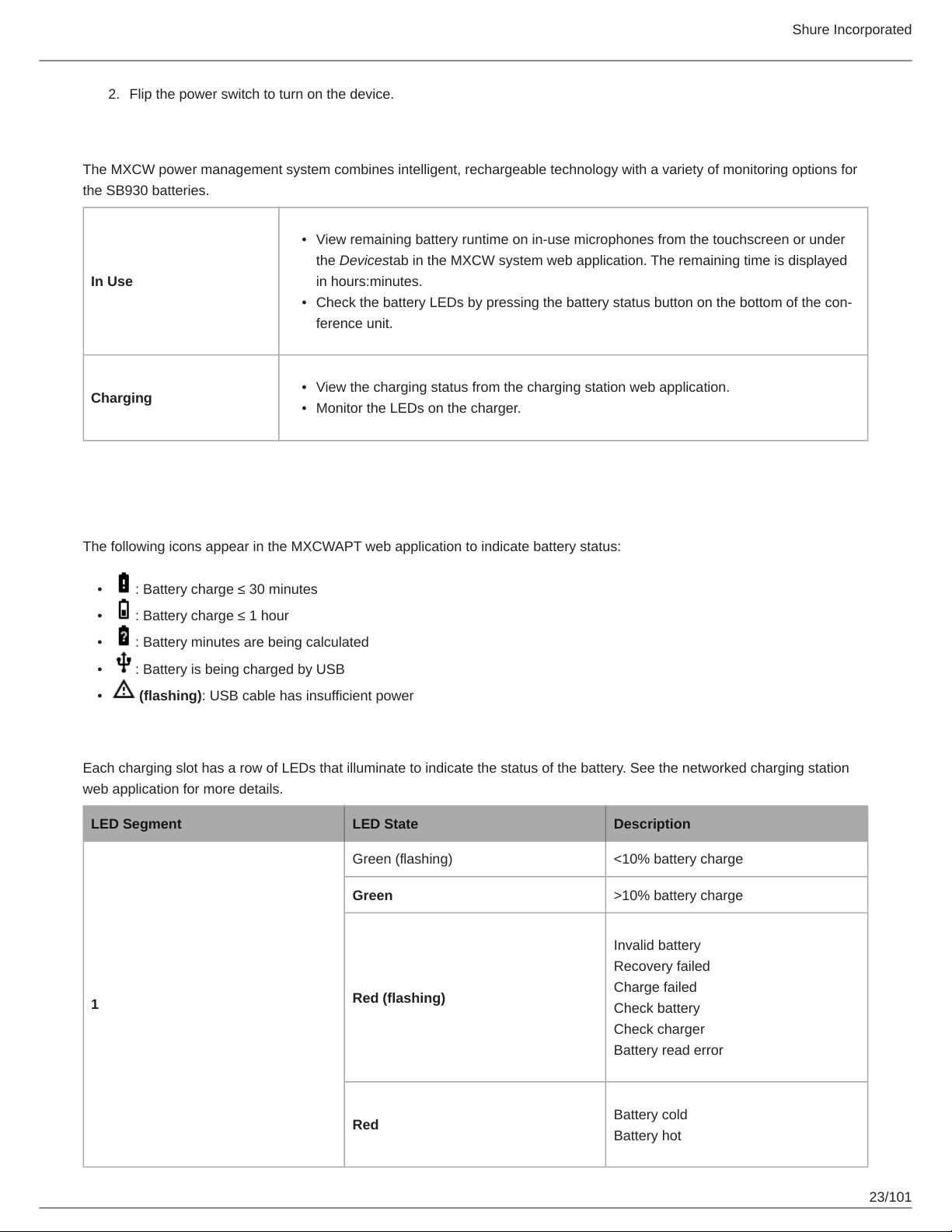
Monitoring Battery Charge
The MXCW power management system combines intelligent, rechargeable technology with a variety of monitoring options for
the SB930 batteries.
•
View remaining battery runtime on in-use microphones from the touchscreen or under
the Devicestab in the MXCW system web application. The remaining time is displayed
In Use
Charging
in hours:minutes.
•
Check the battery LEDs by pressing the battery status button on the bottom of the con
ference unit.
•
View the charging status from the charging station web application.
•
Monitor the LEDs on the charger.
Icons for Charging Batteries
The following icons appear in the MXCWAPT web application to indicate battery status:
•
: Battery charge ≤ 30 minutes
•
: Battery charge ≤ 1 hour
•
: Battery minutes are being calculated
•
: Battery is being charged by USB
•
(flashing): USB cable has insufficient power
Charge Status LEDs
Each charging slot has a row of LEDs that illuminate to indicate the status of the battery. See the networked charging station
web application for more details.
LED Segment LED State Description
Green (flashing) <10% battery charge
Green >10% battery charge
Invalid battery
Recovery failed
1
Red (flashing)
Charge failed
Check battery
Check charger
Battery read error
Red
Battery cold
Battery hot
23/101
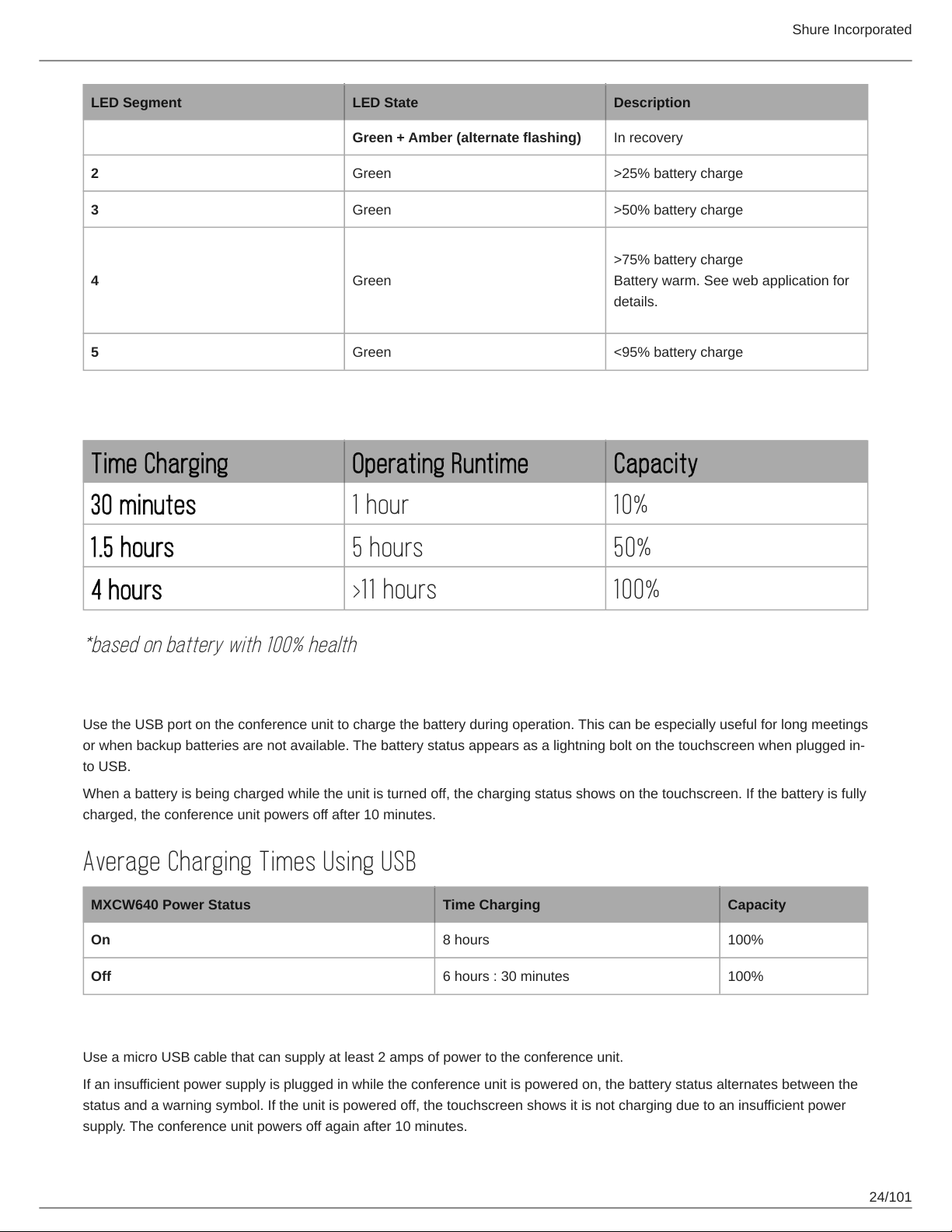
LED Segment LED State Description
Green + Amber (alternate flashing) In recovery
2 Green >25% battery charge
3 Green >50% battery charge
>75% battery charge
4 Green
5 Green <95% battery charge
Battery warm. See web application for
details.
Average Charging Times
Time Charging Operating Runtime Capacity
Shure Incorporated
30 minutes 1 hour 10%
1.5 hours 5 hours 50%
4 hours >11 hours 100%
*based on battery with 100% health
Charging Batteries with USB
Use the USB port on the conference unit to charge the battery during operation. This can be especially useful for long meetings
or when backup batteries are not available. The battery status appears as a lightning bolt on the touchscreen when plugged in
to USB.
When a battery is being charged while the unit is turned off, the charging status shows on the touchscreen. If the battery is fully
charged, the conference unit powers off after 10 minutes.
Average Charging Times Using USB
MXCW640 Power Status Time Charging Capacity
On 8 hours 100%
Off 6 hours : 30 minutes 100%
USB Cable Requirements
Use a micro USB cable that can supply at least 2 amps of power to the conference unit.
If an insufficient power supply is plugged in while the conference unit is powered on, the battery status alternates between the
status and a warning symbol. If the unit is powered off, the touchscreen shows it is not charging due to an insufficient power
supply. The conference unit powers off again after 10 minutes.
24/101
Shure Incorporated
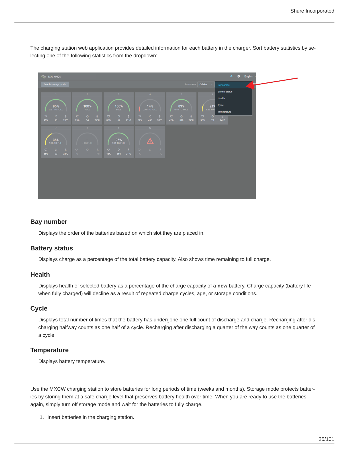
Battery Statistics
The charging station web application provides detailed information for each battery in the charger. Sort battery statistics by se
lecting one of the following statistics from the dropdown:
Bay number
Displays the order of the batteries based on which slot they are placed in.
Battery status
Displays charge as a percentage of the total battery capacity. Also shows time remaining to full charge.
Health
Displays health of selected battery as a percentage of the charge capacity of a new battery. Charge capacity (battery life
when fully charged) will decline as a result of repeated charge cycles, age, or storage conditions.
Cycle
Displays total number of times that the battery has undergone one full count of discharge and charge. Recharging after dis
charging halfway counts as one half of a cycle. Recharging after discharging a quarter of the way counts as one quarter of
a cycle.
Temperature
Displays battery temperature.
Storing Batteries
Use the MXCW charging station to store batteries for long periods of time (weeks and months). Storage mode protects batter
ies by storing them at a safe charge level that preserves battery health over time. When you are ready to use the batteries
again, simply turn off storage mode and wait for the batteries to fully charge.
1.
Insert batteries in the charging station.
25/101
2.
Place the charger in storage mode:
◦
From the hardware: Press and hold the Storage mode button for 5 seconds.
◦
From the software: Open the charger web application to the home page and turn on storage mode.
Installation
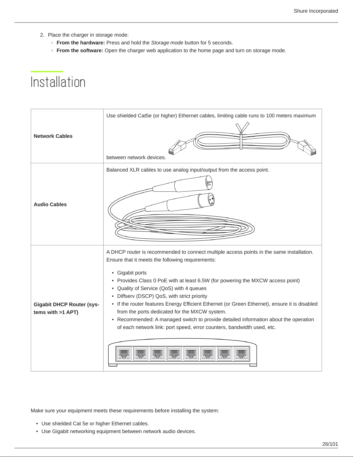
Additional Equipment
Use shielded Cat5e (or higher) Ethernet cables, limiting cable runs to 100 meters maximum
Network Cables
between network devices.
Balanced XLR cables to use analog input/output from the access point.
Shure Incorporated
Audio Cables
Gigabit DHCP Router (sys
tems with >1 APT)
A DHCP router is recommended to connect multiple access points in the same installation.
Ensure that it meets the following requirements:
•
Gigabit ports
•
Provides Class 0 PoE with at least 6.5W (for powering the MXCW access point)
•
Quality of Service (QoS) with 4 queues
•
Diffserv (DSCP) QoS, with strict priority
•
If the router features Energy Efficient Ethernet (or Green Ethernet), ensure it is disabled
from the ports dedicated for the MXCW system.
•
Recommended: A managed switch to provide detailed information about the operation
of each network link: port speed, error counters, bandwidth used, etc.
Requirement Checklist
Make sure your equipment meets these requirements before installing the system:
•
Use shielded Cat 5e or higher Ethernet cables.
•
Use Gigabit networking equipment between network audio devices.
26/101
Shure Incorporated
•
Limiting cable runs to ≤100 m between devices.
•
Same firmware version* for all devices in your system
•
Ensure MXCW components and the PC are on the same network and set to the same subnet.
Tip:*Keep the system upgraded to the latest available firmware version to ensure proper system compatibility and take advan
tage of new features. See Firmware Updates for more information.
Mount the Access Point Transceiver
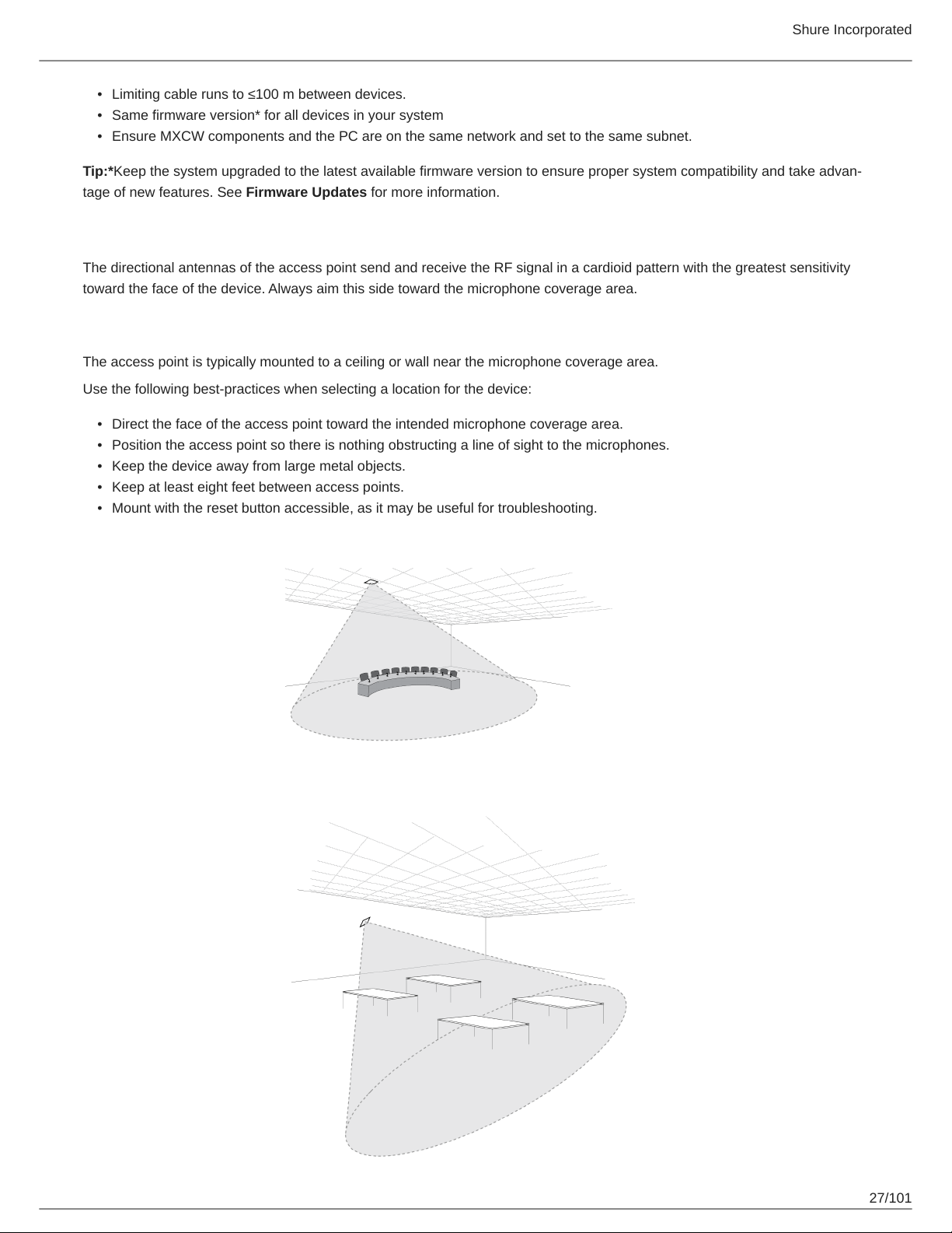
The directional antennas of the access point send and receive the RF signal in a cardioid pattern with the greatest sensitivity
toward the face of the device. Always aim this side toward the microphone coverage area.
Select a Location for the Access Point
The access point is typically mounted to a ceiling or wall near the microphone coverage area.
Use the following best-practices when selecting a location for the device:
•
Direct the face of the access point toward the intended microphone coverage area.
•
Position the access point so there is nothing obstructing a line of sight to the microphones.
•
Keep the device away from large metal objects.
•
Keep at least eight feet between access points.
•
Mount with the reset button accessible, as it may be useful for troubleshooting.
27/101
Shure Incorporated
Important: Always perform a "walk around" test to verify coverage before using a wireless system during a speech or perfor
mance. Experiment with placement to find the optimum location. If necessary, mark "trouble spots" and ask presenters or per
formers to avoid those areas.
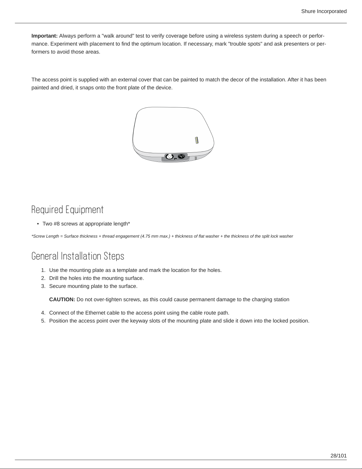
External Cover for Painting
The access point is supplied with an external cover that can be painted to match the decor of the installation. After it has been
painted and dried, it snaps onto the front plate of the device.
Securing to a Wall or Ceiling
Required Equipment
•
Two #8 screws at appropriate length*
*Screw Length = Surface thickness + thread engagement (4.75 mm max.) + thickness of flat washer + the thickness of the split lock washer
General Installation Steps
1.
Use the mounting plate as a template and mark the location for the holes.
2.
Drill the holes into the mounting surface.
3.
Secure mounting plate to the surface.
CAUTION: Do not over-tighten screws, as this could cause permanent damage to the charging station
4.
Connect of the Ethernet cable to the access point using the cable route path.
5.
Position the access point over the keyway slots of the mounting plate and slide it down into the locked position.
28/101
Shure Incorporated
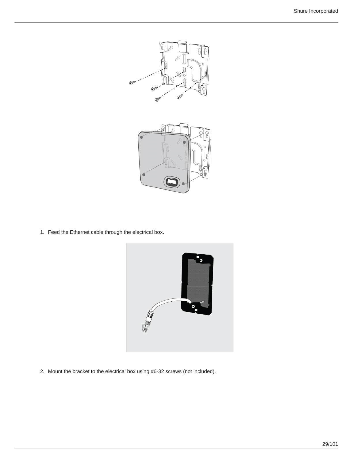
Mounting at an Electrical Box
1.
Feed the Ethernet cable through the electrical box.
2.
Mount the bracket to the electrical box using #6-32 screws (not included).
29/101
Shure Incorporated
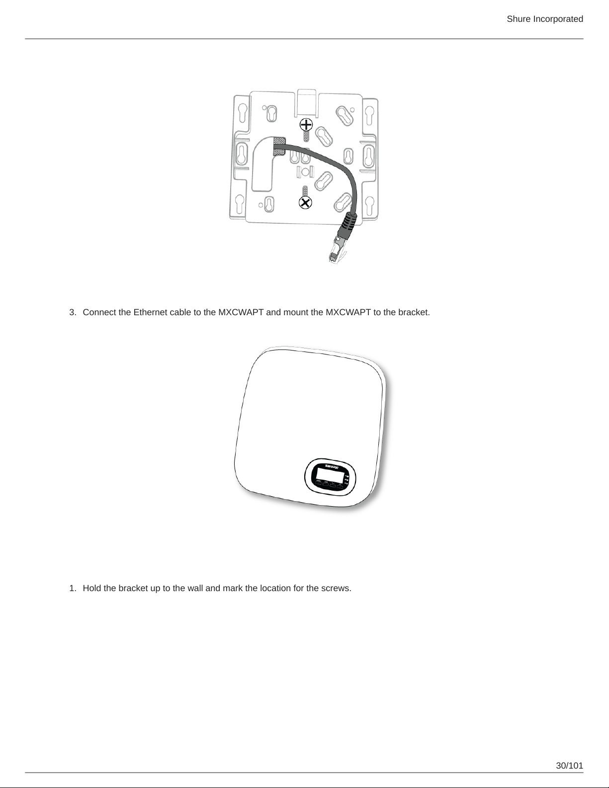
3.1.Connect the Ethernet cable to the MXCWAPT and mount the MXCWAPT to the bracket.
Mounting in Drywall
Hold the bracket up to the wall and mark the location for the screws.
30/101
 Loading...