

Page 1
Low-Profile Boundary Microphone
www.shure.com
© 2014 Shure Incorporated
27A3237 (Rev. 6)
Page 2
MX395 Low-Profile Boundary
+5 V
GND
MX395
Device
Logic Port (I/O)
Green
Red
Logic HIGH (+5 V)
Logic LOW (0 V)
Audio −
Audio +
42
51
3
Audio −
Audio +
Logic (LED IN)
Microphone
General Description
Shure® MX395 low-profile microphones are for use
in boardrooms and other sites where aesthetics
are important. The MX395 is only 2.5 cm (1 in.) in
diameter, and extends just 2 cm above the mounting surface when installed. Despite its small size,
the MX395 delivers clear, high quality sound.
Features
• Low profile, aesthetic design
• Wide dynamic range and smooth frequency
response
• RF filtering with CommShield
• Available with logic-controlled bi-color status
indicator
Model Variations
The MX395 is available in cardioid, omnidirectional, and bidirectional polar patterns, with or without
an LED status indicator, with a black, white, or
aluminum finish.
®
technology
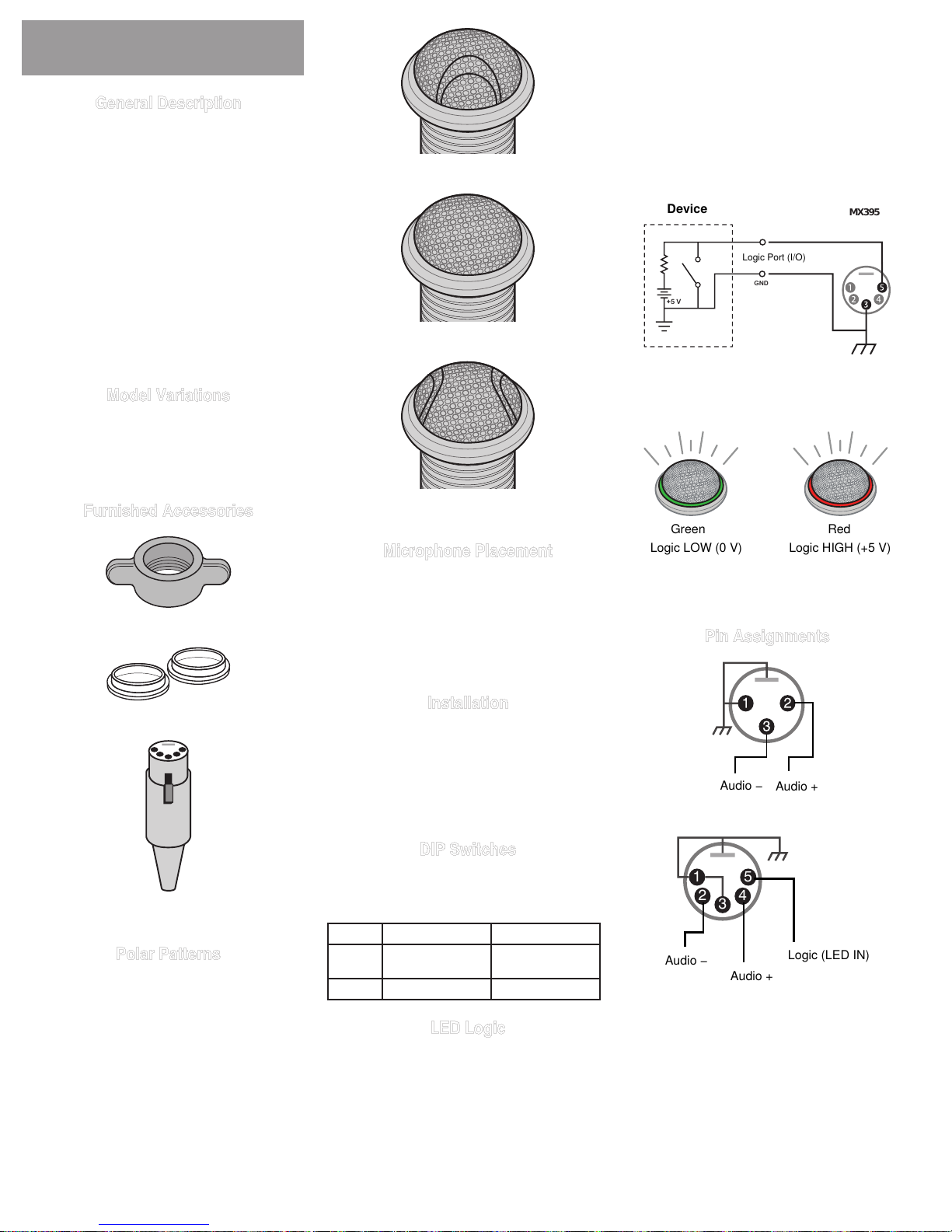
Cardioid
Omnidirectional
Note: Connect the LED IN to the gate output to il-
luminate the LED when the channel is gated on.
Do not use the relay ports on Crestron and AMX
devices. Use the I/O logic ports instead.
The LED logic may not function when connecting
to devices that do not have internal "pull-up resistor" logic circuits, such as ClearOne DSP products.
External pull-up resistor circuits can be added for
each microphone. Vistit www.shure.com/FAQ for
detailed instructions.
Logic Connection
Connection to device with internal "pull-up
resistor" logic circuit
Furnished Accessories
Wing Nut
Rubber Isolation Ring
5-pin XLR, Female (MX395-LED variations)
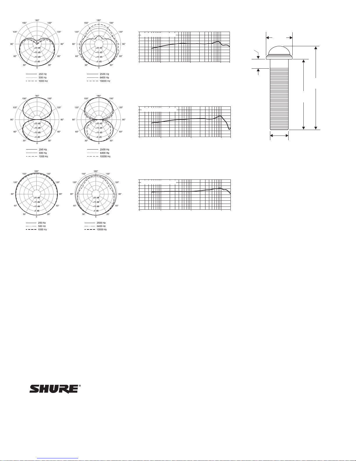
Polar Patterns
The polar pattern is indicated by the molded grille.
Bidirectional
Microphone Placement
For best low-frequency response and rejection
of background noise, place the microphone on a
large, flat surface, such as a floor, table, or lectern.
To reduce reverberance, avoid reflective surfaces
above or to the side of the microphone, such as
beveled sides of pulpits or overhanging shelves.
Installation
Install the microphone into a tabletop as shown.
Important:
• Align indentation toward talker
• Do not over tighten the wing nut, as this reduces
shock isolation
DIP Switches
Set DIP Switch 1 up to engage the low cut filter,
which attenuates frequencies by 6 dB per octave
below 150 Hz.
Switch Down (default) Up
1 Full frequency
response
2 -- --
Low cut filter
LED Logic
For models equipped with an LED, use the included 5-pin XLR connector to wire the microphone to
an automatic mixer or other logic device.
LED Indicator Response to Logic Signal at Pin 5
Pin Assignments
3-Pin XLR
5-Pin XLR
2
Page 3
Specifications
All measurements taken with microphone mounted on a wooden
surface (76 x 76 cm)
Cartridge Type
Electret Condenser
Frequency Response
50–17000 Hz
Polar Pattern
MX395/O Omnidirectional
MX395/C Cardioid
MX395/BI Bidirectional
Output Impedance
170Ω
Output Configuration
Active Balanced
Sensitivity
@ 1 kHz, open circuit voltage
Cardioid −34dBV/Pa(20mV)
Omnidirectional −29dBV/Pa(36mV)
Bidirectional −35dBV/Pa(18mV)
1 Pa=94 dB SPL
Maximum SPL
1kHzat1%THD,1kΩload
Cardioid 120 dB
Omnidirectional 115 dB
Bidirectional 121 dB
Equivalent Output Noise
A-weighted
Cardioid 29 dB SPL
Omnidirectional 23 dB SPL
Bidirectional 27 dB SPL
Signal-to-Noise Ratio
Ref. 94 dB SPL at 1 kHz
Cardioid 65 dB
Omnidirectional 72 dB
Bidirectional 67 dB
Dynamic Range
1kΩload,@1kHz
Cardioid 91 dB
Omnidirectional 92 dB
Bidirectional 95 dB
Common Mode Rejection
10 to 100,000 kHz
45 dB, minimum
Preamplifier Output Clipping Level
at 1% THD
−8dBV(0.4V)
Logic Connections
LED IN Activelow(≤1.0V),TTLcompatible.
Net Weight
137 g (0.30 lbs)
Absolute maximum voltage: -0.7V
to 50V.
Environmental Conditions
Operating Temperature –18–57°C
(0–135°F)
Storage Temperature
–29–74°C
(–20–165°F)
Relative Humidity 0–95%
Power Requirements
MX395 11–52 V DC, 2.0 mA
MX395-LED 48–52VDC,8.0mA
Certifications
Meets essential requirements of all applicable
European Directives.
Eligible for CE marking.
The CE Declaration of Conformity can be obtained from Shure Incorporated or any of its
European representatives. For contact information
please visit www.shure.com
The CE Declaration of Conformity can be obtained from: www.shure.com/europe/compliance
Authorized European representative:
Shure Europe GmbH
Headquarters Europe, Middle East & Africa
Department: EMEA Approval
Jakob-Dieffenbacher-Str. 12
75031 Eppingen, Germany
Phone: 49-7262-92 49 0
Fax: 49-7262-92 49 11 4
Email: [email protected]
Preamp Gain
If necessary, the preamplifier gain can be reduced
by 12 dB. Contact an authorized Shure service
center for information.
3
Page 4
MX395/C
20
MX395/BI
MX395/O
20
15
0,6 m (2 ft.) from sound source
10
5
0
-5
dB
-10
-15
-20
-25
-30
20 100 1k 10k 20k
15
0,6 m (2 ft.) from sound source
10
5
0
-5
dB
-10
-15
-20
-25
-30
20 100 1k 10k 20k
Hz
Hz
7/16 in
(12 mm)
1 1/4 in
(32 mm)
7/8 in
(22 mm)
3 3/8 in
(86 mm)
4 in
(101 mm)
20
15
0,6 m (2 ft.) from sound source
10
5
0
-5
dB
-10
-15
-20
-25
-30
20 100 1k 10k 20k
Hz
United States, Canada, Latin
America, Caribbean:
Shure Incorporated
5800 West Touhy Avenue
Niles, IL 60714-4608 USA
Phone: +1-847-600-2000
www.shure.com
Fax: +1-847-600-1212 (USA)
Fax: +1-847-600-6446
Email: [email protected]
Europe, Middle East, Africa:
Shure Europe GmbH
Jakob-Dieffenbacher-Str. 12,
75031 Eppingen, Germany
Phone: +49-7262-92490
Fax: +49-7262-9249114
Email: [email protected]
Asia, Pacific:
Shure Asia Limited
22/F, 625 King’s Road
North Point, Island East
Hong Kong
Phone: 852-2893-4290
Fax: 852-2893-4055
Email: [email protected]
 Loading...