

Page 1
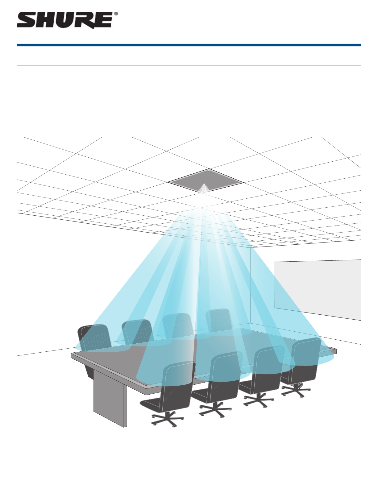
MXA910
Ceiling Array Microphone
Overview
General Description
The Microflex®Advance™ Ceiling Array is a premium networked array microphone for AV conferencing environments, including boardrooms, huddle rooms,
and multi-purpose spaces. Revolutionary technology from the IntelliMix®DSP suite includes Steerable Coverage ™ , with eight highly directional pickup lobes
that capture participant audio from overhead. Browser-based control software provides an intuitive user interface for microphone attributes, including lobe configuration, automatic mix settings, and preset templates. The microphone integrates seamlessly with Dante™ digital networked audio and third-party preset
controllers, including Crestron and AMX, to deliver a high-quality AV conferencing experience that appeals equally to integrators, consultants, and meeting
participants.
1/57©2017 Shure Incorporated
Page 2
Features
Configurable Coverage
• Steerable Coverage™ delivers precise pickup for up to 8 independent lobes
•
IntelliMix®DSP Suite provides fast-acting automatic mixing, echo reduction, and channel equalization
Software Control
• Intuitive software interface provides comprehensive microphone and pattern control
• Includes templates to speed initial set-up and 10 customizable presets to import or export configurations between multiple microphones
Network Connectivity
• Discrete audio channels for each lobe and an automix channel are delivered over a single network cable
• Dante™ digital audio coexists safely on the same network as IT and control data, or can be configured to use a dedicated network
• Control strings available for third-party preset controllers including Crestron and AMX
Professional Design
• Sleek industrial design blends with contemporary board rooms and meeting spaces
• Seamless flush-mount with standard ceiling tiles
• Available in white, black, and aluminum finishes (detachable grille can be custom painted)
Shure IncorporatedMXA910 Ceiling Array Microphone
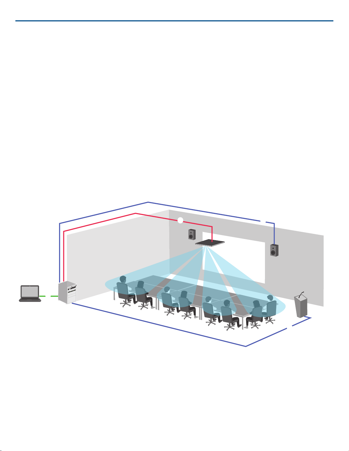
System Overview
① Dante audio, power, and control
Each array microphone connects to the network over a single network cable, which carries Dante™ audio, Power over Ethernet (PoE), and control information
to adjust coverage, audio levels, and processing.
② Analog audio (microphone to network)
Analog equipment, such as a wireless microphone system or a gooseneck microphone on a podium, connects to the Dante™ audio network through a Shure
Network Interface (model ANI4IN) for a completely networked conferencing system.
③ Far-end audio (network to loudspeakers)
Dante™ -enabled loudspeakers and amplifiers connect directly to a network switch. Analog loudspeakers and amplifiers connect through a Shure Network Interface (model ANI4OUT), which converts Dante™ audio channels into analog signals, delivered through 4 discrete XLR or block connector outputs.
④ Device control and Dante™ audio
2017/10/182/57
Page 3
reset
PoE
INPUT
reset
PoE
INPUT
sig/clip
power
reset
PoE
network
network audio
encryption
1
1
2
234
3
4
OUTPUT
sig/clip
power
reset
PoE
network
network audio
encryption
1
1
2
234
3
4
OUTPUT
ULXD4Q
Digital Wireless Receiver
push
control
ENTER
EXIT
SCAN
power
RF
AB
OL
OL
gainaudio
RF
AB
OL
OL
gainaudio
RF
AB
OL
OL
gainaudio
RF
AB
OL
OL
gainaudio
RX1 RX2 RX3 RX4
IR
sync
sync sync sync
SEL
SEL
ULXD4Q
Digital Wireless Receiver
push
control
ENTER
EXIT
SCAN
power
RF
AB
OL
OL
gainaudio
RF
AB
OL
OL
gainaudio
RF
AB
OL
OL
gainaudio
RF
AB
OL
OL
gainaudio
RX1 RX2 RX3 RX4
IR
sync
sync sync sync
SEL
SEL
ULXD1
ULXD1
on
ULXD2
on
ULXD2
ULXD4Q
Digital Wireless Receiver
push
control
ENTER
EXIT
SCAN
power
RF
AB
OL
OL
gainaudio
RF
AB
OL
OL
gainaudio
RF
AB
OL
OL
gainaudio
RF
AB
OL
OL
gainaudio
RX1 RX2 RX3 RX4
IR
sync
sync sync sync
SEL
SEL
ULXD4Q
Digital Wireless Receiver
push
control
ENTER
EXIT
SCAN
power
RF
AB
OL
OL
gainaudio
RF
AB
OL
OL
gainaudio
RF
AB
OL
OL
gainaudio
RF
AB
OL
OL
gainaudio
RX1 RX2 RX3 RX4
IR
sync
sync sync sync
SEL
SEL
ULXD1
ULXD1
on
ULXD2
on
ULXD2
Dante
Analog
Microflex Advance microphones
Analog microphones
Loudspeakers
Option 1 (VOIP/TELCO)
Option 2 (Internet/DVS)
Near end
Far end
Network switch
Network interface (ANI4IN)
Network interface (ANI4OUT)
Shure IncorporatedMXA910 Ceiling Array Microphone
Control:A computer connected to the network controls the microphone through a web-based control application. Coverage, muting, LED behavior, lobe settings,
gain, and network settings are controlled remotely.
Audio: Dante™ audio is routed through Dante™ controller software. Dante™ Virtual Soundcard enables audio monitoring and recording directly on the
computer.
System Planning and Gear Requirements
Setting up the Audio Network
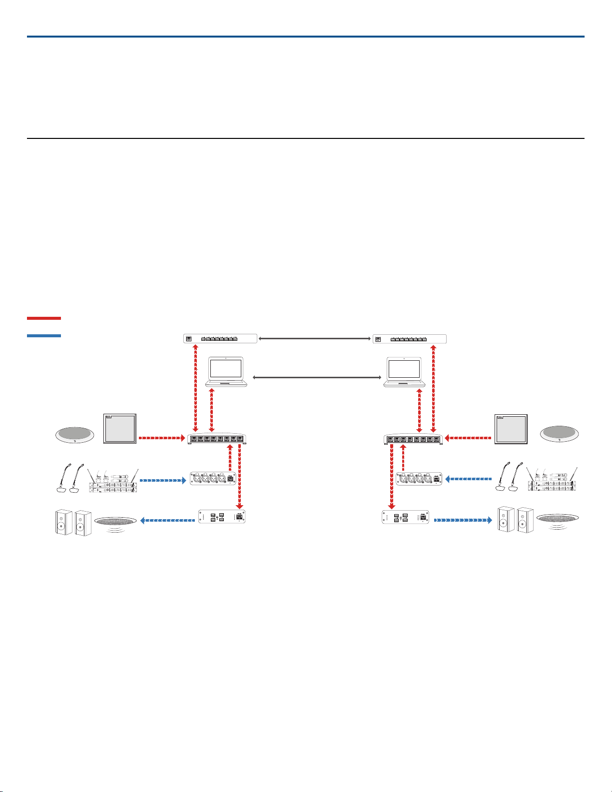
Shure networked conferencing systems are comprised of Microflex Advancemicrophones and network interfaces, which operate entirely on a Dante™ network.
Additional hardware, including network switches, computers, loudspeakers, and audio processors are described in the hardware component index.
Shure components shown in this diagram:
Microflex Advance Microphones
The MXA910 and MXA310 are equipped with Dante outputs, and connect directly to a network switch.
Audio Network Interfaces
The interfaces are used to connect analog devices such as loudspeakers and analog microphones to the network.
ANI4IN: Converts 4 analog signals (separate XLR and block connector models available) into Dante™ digital audio signals.
ANI4OUT:Converts 4 channels of Dante™ audio from the network into analog signals.
This diagram shows the entire signal path through a networked conference system. Signals from the near end and far end are exchanged through an audio
processor connected to a phone system, or through a computer connected to the internet. Analog microphones connect to the network through the Shure ANI4IN,
while loudspeakers connect through the Shure ANI4OUT.
3/572017/10/18
Page 4

sig/clip
power
network
network audio
encryption
1
2
3
4
sig/clip
power
network
network audio
encryption
1
2
3
4
sig/clip
power
network
network audio
encryption
1
2
3
4
ROOM A SIGNAL
ROOM B SIGNAL
sig/clip
power
network
network audio
encryption
1
2
3
4
sig/clip
power
network
network audio
encryption
1
2
3
4
MXA910
MXA910
MXA310
MXA310
ANI4IN
ANI4IN
ANI4OUT
ANI4OUT
ANI4OUT
NETWORK SWITCH
NETWORK SWITCH NETWORK SWITCH
VIDEO CODEC
VIDEO CODEC
VIDEO CODEC
LOUDSPEAKERS
ANALOG MICROPHONES
1
1
1
2
2
2
3
3
4
4
4
5
5
5
6
6
6
7
7
8
8
Dante Signals
Analog Signals
Shure IncorporatedMXA910 Ceiling Array Microphone
This diagram shows Microflex Advance components in context, with two rooms communicating through video codecs.
Controlling Hardware and Audio Over the Network
Audio and hardware settings are managed through a computer connected to the same network.
Shure Hardware and Audio
Each Microflex Advance component has a web application which provides mixing and configuration tools to optimize sound quality.
Expanded Control for Analog Devices
Analog devices that are connected to the network through a Shure network interface (ANI4IN/ANI4OUT) benefit from additional remote control: Volume levels,
equalization, and signal routing are managed through the web application. For example, adjusting loudspeaker volume or muting a wired microphone, which
would normally be done from the hardware, can now be controlled remotely over the network.
Dante™ Signal Routing
Signal routing between devices is managed through Dante Controller software, provided by Audinate™ .
2017/10/184/57
Page 5
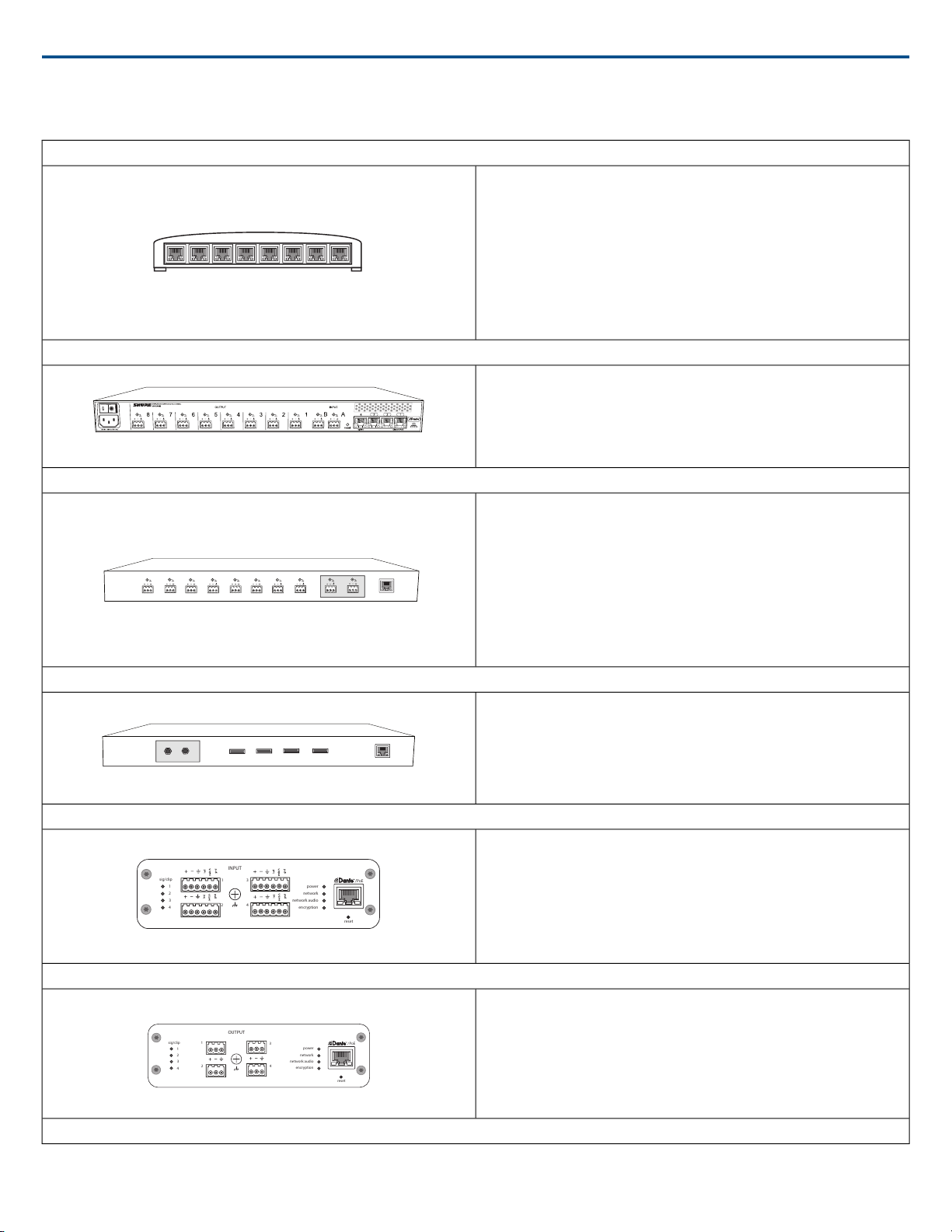
Hardware Component Index
sig/clip
power
reset
PoE
network
network audio
encryption
1
1
2
234
3
4
INPUT
sig/clip
power
reset
PoE
network
network audio
encryption
1
1
2
2
3
4
3
4
OUTPUT
Shure IncorporatedMXA910 Ceiling Array Microphone
Network Switch
The network switch provides central connectivity for all networked components.
Audio from any networked Shure microphones that are connected to the switch
can be routed to any Dante™ -enabled device. The switch sends and receives
audio and control data, while simultaneously powering the microphones and
audio network interfaces through PoE(Power over Ethernet). See the network
switch requirements for additional details.
Power over Ethernet (PoE) Requirements:
All Shure components included in these scenarios require Power over Ethernet
(class 0). If not provided through the network switch, a PoE injector is required
to power the devices.
Shure Microflex Wireless Audio Network Interface (MXWANI)
The Microflex Wireless Audio Network Interface (MXWANI) is a digital-to-analog
breakout box with a built-in gigabit network switch. It converts digital audio from
the network into analog signals for signal processing or amplification, and
provides PoE over one network port to power a device. For details, refer to the
Microflex Wireless user guide, available at http://www.shure.com.
Audio Processor
The audio processor sends and receives audio through a VOIP server or a
standard phone line. They also provide digital signal processing, such as
acoustic echo cancellation.
Dante™ -enabled
Processors that support Dante™ connect directly to the network switch to re-
ceive audio from Microflex Advance microphones.
When using an analog processor, a converter (such as the Shure ANI4OUT
or MXWANI) is required to deliver the analog audio from Microflex Advance
microphones to the processor.
Video Codec
Like the audio processor, the codec sends and receives audio signals alongside
video signals between the near end and the far end. Audio from the near end
must connect to the audio input on the video codec, which is typically a stereo
analog connection. The Shure ANI4OUT Audio Network Interfaceconverts the
audio to an analog signal for connecting to a codec.
Shure ANI4IN Audio Network Interface (Analog-to-Dante Converter)
The Shure ANI4IN Audio Network Interface converts 4 channels of analog audio
into independent digital audio channels on a Dante™ network. Adjustable gain
and +48V phantom power deliver the flexibility to support line, auxiliary, and
microphone-level devices. For networked conferencing systems, the Audio
Network Interface provides a simple way to connect previously installed analog
equipment onto the audio network, such as wireless microphones for presenters.
The web application gives technicians and administrators control over channel
levels and settings from any computer connected to the same network.
Shure ANI4OUT Audio Network Interface (Dante-to-Analog Converter)
Analog
The Shure ANI4OUT Audio Network Interface converts 4 channels of Dante™
digital audio into discrete analog signals. Available in both XLR and block
connector versions, each box uses a single network cable to receive audio and
power using Power over Ethernet (P oE). The web application gives technicians
and administrators control over channel levels and settings from any computer
connected to the same network.
Amplifiers and Loudspeakers
5/572017/10/18
Page 6
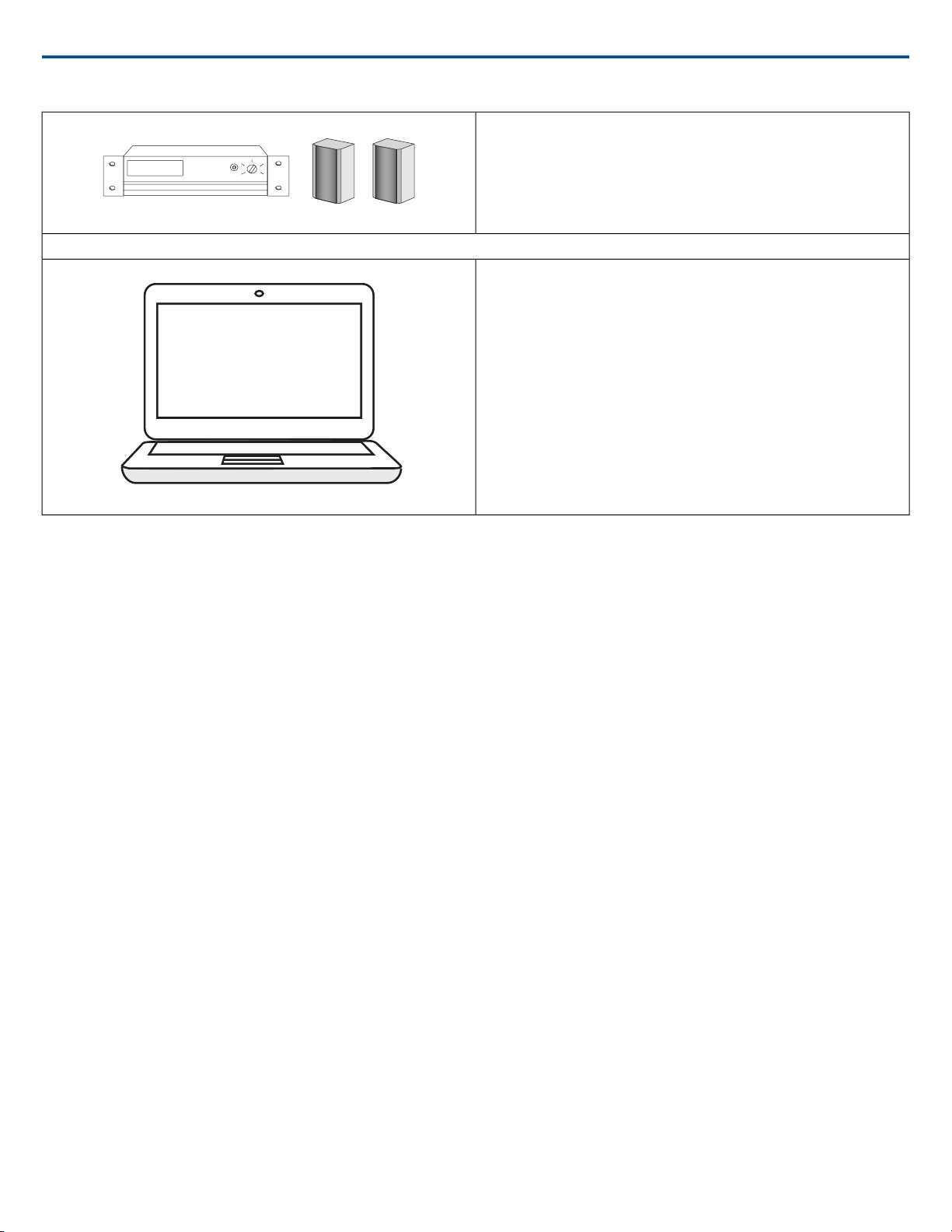
Audio from the far end is routed to local loudspeakers. Dante™ -enabled
speakers or amplifiers connect directly to the network switch, while analog
systems require an audio network interface to receive networked audio.
Computers and Control Systems
Shure IncorporatedMXA910 Ceiling Array Microphone
A computer connected to the network provides control of Shure networked
components through the web application for each device.
A computer running Dante™ Virtual Soundcard, Dante™ Controller, and web
conferencing software is used to send and receive audio between the near end
If using a third-party control system, Microflex Advance microphones send and
receive commands over Ethernet. If an analog logic signal must be sent over
the network, the Shure ANI4IN Audio Network Interface receives analog logic
signals and converts them into Ethernet control strings.
Browser-Based Web Application
Dante™ Software
and far end.
Control Systems (AMX, Crestron, etc.)
System Scenarios
The following diagrams show a selection of common conferencing room systems. Use them as a reference when planning hardware and cable requirements
for an installation. Each diagram includes:
• Signal flow and connections
• Required hardware
• Component roles
Power Over Ethernet and Hardware Requirements
All Shure components included in these scenarios require Power over Ethernet (P oE, class 0). Refer to the Dante and Networking section for additional infor-
mation on cable and network switch requirements.
2017/10/186/57
Page 7
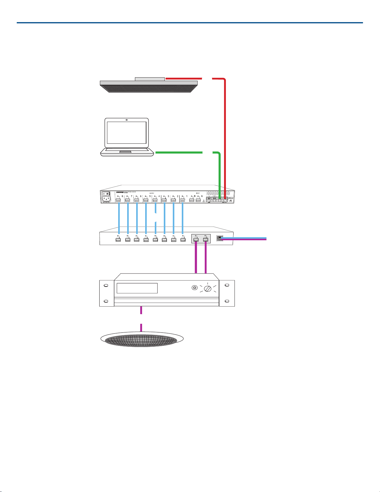
Telephone Conference with Shure MXW Network Interface
Ceiling array microphone
Software control
MXW Audio Network Interface
Audio processor
Amplifier
Ceiling speaker
Shure IncorporatedMXA910 Ceiling Array Microphone
① Array microphone to Shure MXWANI
Connect the microphone output to port 1 on the MXWANI with a network cable. Port 1 provides the necessary Power over Ethernet (PoE).
② Computer to Shure MWXANI
Connect a computer to the ANI on port 2 or 3 with a network cable to provide control of the array microphone and other networked components.
③ Shure ANI analog outputs to audio processor
Step 1: Route signals with Dante™ Controller software
Route the channels from the microphone (Dante transmitter) to the MXWANI channels (Dante receiver). This establishes the discrete channels to deliver through
the analog outputs.
Step 2: Connect the MXWANI outputs to the processing device inputs
Block connector outputs on the MXWANI send balanced audio signals to the inputs on the processing device, which provides digital signal processing (such as
acoustic echo cancellation).
④ Connection to far end
Connect the audio processor to a VOIP server or telephone line to send and receive audio between the near end and far end.
7/572017/10/18
Page 8
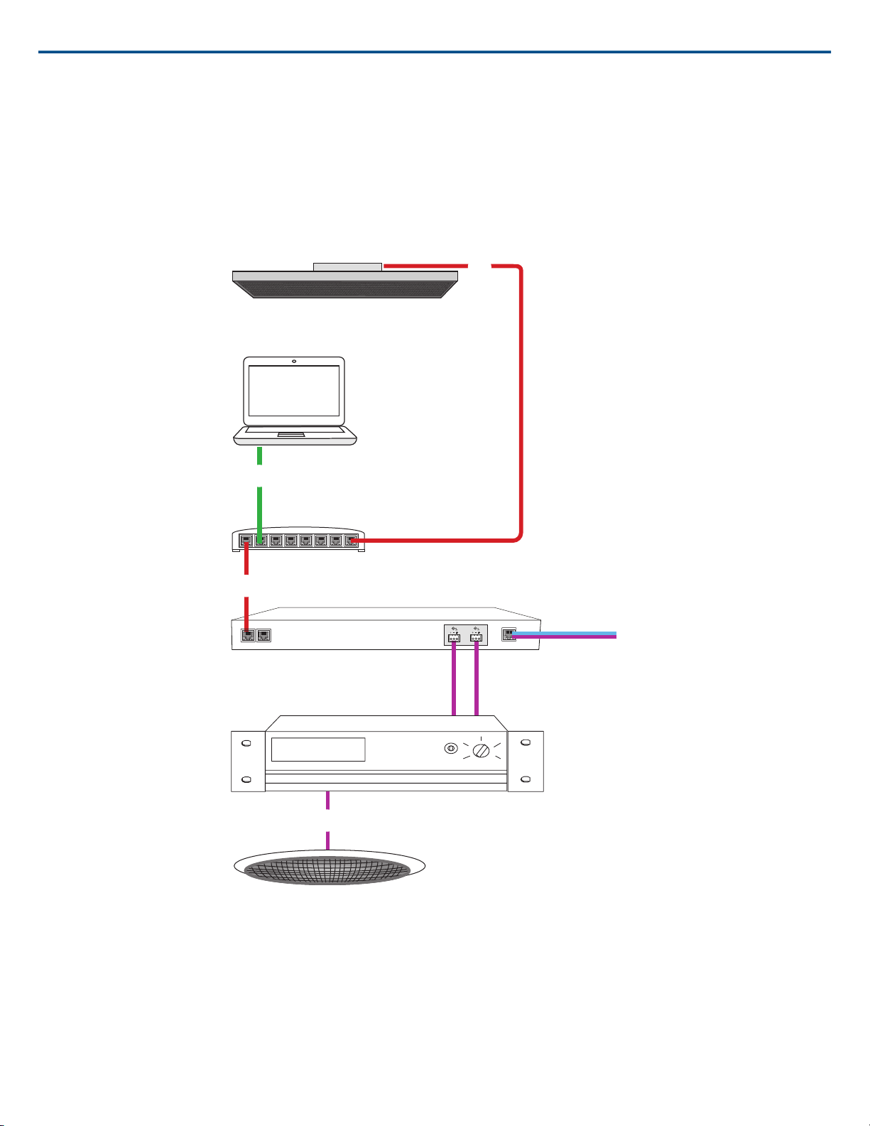
⑤ Audio from far end to amplifier
Ceiling array microphone
Software control
Network switch
Dante audio processor
Amplifier
Ceiling Speaker
Route the far end audio through the audio processor output to an amplifier.
⑥ Amplified audio signal to loudspeakers
Connect the loudspeakers to the amplifier to hear the audio from the far end.
Telephone Conference with Dante™ -enabled Audio Processor
Shure IncorporatedMXA910 Ceiling Array Microphone
① Array microphone to network switch
Connect the array microphone output with a network cable to any port on the switch that supplies Power over Ethernet (PoE).
② Computer to network switch
Connect a computer to the network switch to provide control of the array microphone and other networked components.
③ Network switch to Dante™ audio processor
Connect the Dante™ audio processor to the network switch to provide:
• Digital signal processing (acoustic echo cancellation)
• Digital-to-analog conversion to deliver Dante™ audio over an analog (VOIP or telephone line) output.
2017/10/188/57
Page 9
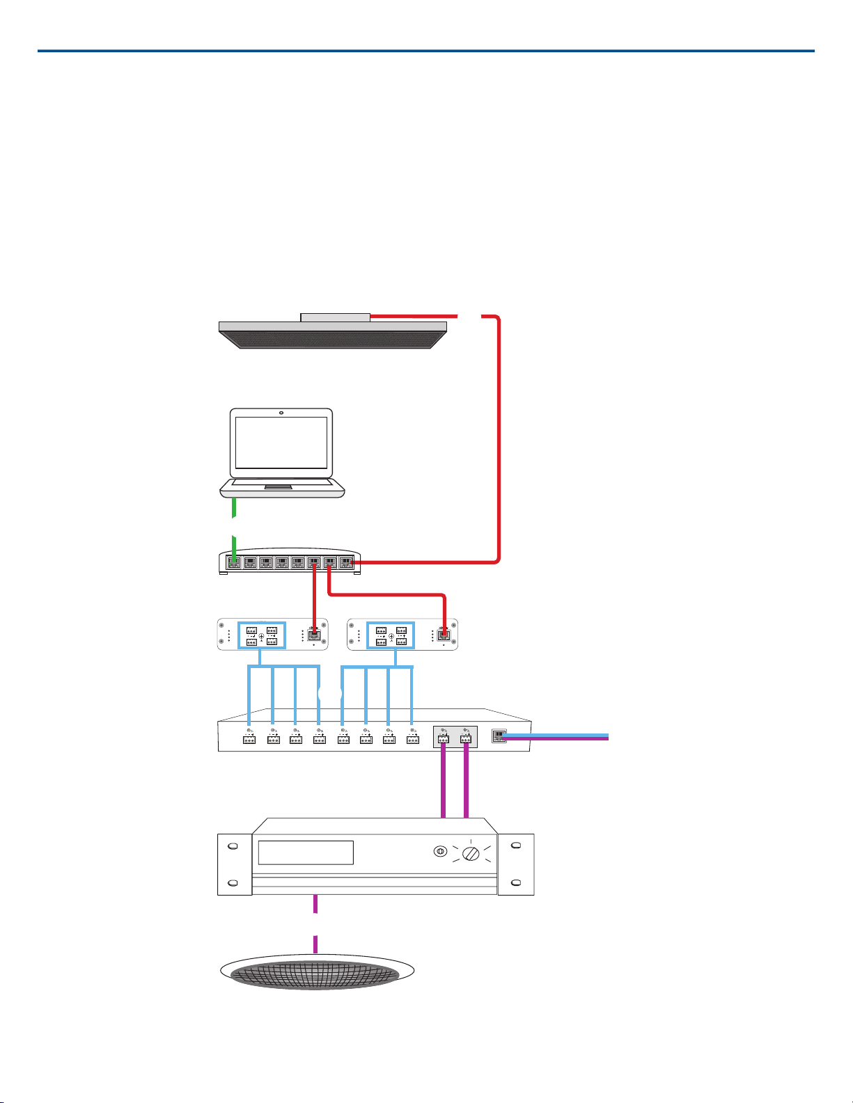
• Analog-to-digital conversion to deliver analog audio from the far end onto the Dante™ network.
sig/clip
power
reset
PoE
network
network audio
encryption
1
1
2
2
3
4
3
4
OUTPUT
sig/clip
power
reset
PoE
network
network audio
encryption
1
1
2
2
3
4
3
4
OUTPUT
Ceiling array microphone
Software control
Network switch
Shure ANI4OUT
Amplifier
Ceiling speaker
④ Connection to far end
Connect the output from the audio processor to a VOIP server or telephone line to deliver audio between the near end and far end.
⑤ Audio from far end to amplifier
Route the far end audio through the audio processor output to an amplifier.
⑥ Amplified audio signal to loudspeakers
Connect the loudspeakers to the amplifier to deliver the audio from the far end.
Telephone Conference with Network Interfaces and Audio Processor
Shure IncorporatedMXA910 Ceiling Array Microphone
① Array microphone to network switch
Connect the array microphone output with a network cable to any port on the switch that supplies power over ethernet (PoE).
9/572017/10/18
Page 10

Shure IncorporatedMXA910 Ceiling Array Microphone
② Computer to network switch
Connect a computer to the network switch to provide control of the array microphone and other networked components through the software control panel.
③ ANI4OUT (digital-to-analog conversion)
From the network switch:Use network cables to connect each ANI4OUT to the network switch. A single ANI4OUT receives 4 channels of Dante™ audio,
and converts them to 4 analog signals, delivered through XLR outputs or block connectors. Using two of them, all 8 channels from the array microphone can
be connected to analog inputs on an audio processing device.
To a processing device: Route the ANI4OUT outputs to the processing device inputs to provide digital signal processing (acoustic echo cancellation).
④ Connection to far end
Connect the output from the audio processor to a VOIP server or telephone line to deliver audio between the near end and far end.
⑤ Audio from far end to amplifier
Route the far end audio through the audio processor output to an amplifier.
⑥ Amplified audio signal to loudspeakers
Connect the loudspeakers to the amplifier to deliver the audio from the far end
2017/10/1810/57
Page 11
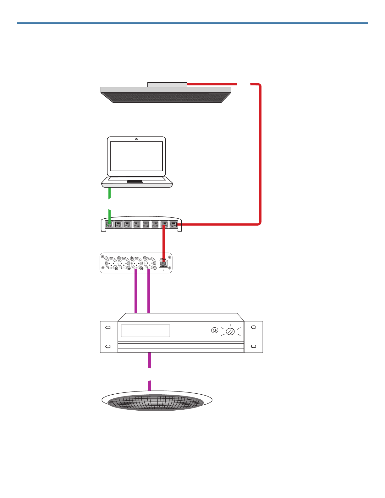
Web Conferencing Software With Dante™ Virtual Soundcard
reset
PoE
OUTPUT
Ceiling array microphone
Network switch
Shure ANI4OUT
Ceiling speaker
Shure IncorporatedMXA910 Ceiling Array Microphone
① Array microphone to network switch
Connect the array microphone output with a network cable to any port on the switch that supplies Power over Ethernet (PoE).
② Computer to network switch
Connect a computer to the network switch to provide control of the array microphone and other networked components through the software control panel. The
computer also runs Dante™ Virtual Soundcard, Dante™ Controller, and the web conferencing software.
11/572017/10/18
Page 12

Shure IncorporatedMXA910 Ceiling Array Microphone
• Dante™ Virtual Soundcard / Controller: Turn on the Dante™ Virtual Soundcard and use the controller software to route the array microphone signal to
the computer.
• Web Conferencing Software:Assign the audio input and output device settings to the appropriate Dante transmitter and receiver channels.
③ Network switch to ANI4OUT
Use network cables to connect each ANI4OUT to the network switch. Each interface receives 4 channels of Dante audio, and converts them to 4 analog signals,
delivered through XLR outputs or block connectors.
④ Audio from far end to amplifier
Route the far end audio to an amplifier.
⑤ Amplified audio signal to loudspeakers
Connect the loudspeakers to the amplifier to deliver the audio from the far end.
2017/10/1812/57
Page 13
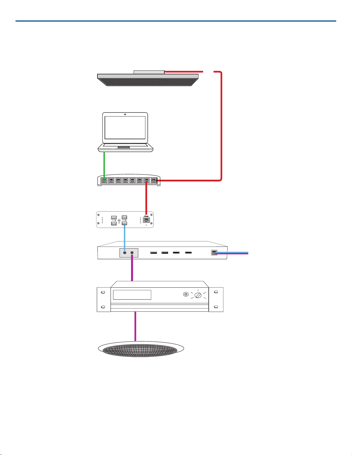
Video Conference
sig/clip
power
reset
PoE
network
network audio
encryption
1
1
2
2
3
4
3
4
OUTPUT
Ceiling array microphone
Software control
Network switch
Shure ANI4OUT
Video codec
Ceiling speaker
Shure IncorporatedMXA910 Ceiling Array Microphone
① Array microphone to network switch
Connect the array microphone output with a network cable to any port on the switch that supplies power over ethernet (PoE).
② Computer to network switch
Connect a computer to the network switch to provide control of the array microphone and other networked components through the software control panel.
③ ANI4OUT (digital-to-analog conversion)
Each ANI4OUT receives 4 channels of Dante audio, and converts them to 4 analog signals, delivered through XLR outputs or block connectors.
Input: Connect the ANI4OUT to the network switch with a network cable
Ouput: Connect the analog output to the audio input on the video codec
13/572017/10/18
Page 14

Shure IncorporatedMXA910 Ceiling Array Microphone
④ Video codec connection to far end
Connect the codec to the appropriate network to connect with the far end.
⑤ Audio from far end to amplifier
Route the far end audio through the video codec audio output to an amplifier.
⑥ Amplified audio signal to loudspeakers
Connect the loudspeakers to the amplifier to deliver the audio from the far end.
Installation
Microphone Placement
Room Variables
Optimal microphone placement is determined by the seating arrangements and infrastructure. Follow these guidelines for the best possible results:
• In rooms with flexible furniture arrangements or multiple array microphones, use the microphone configuration tool in the web application to ensure that the
coverage is adequate for all seating scenarios.
• The lobes should be pointed towards the front of each talker. Carefully consider placement in rooms where talkers may face a screen during a video conference.
• Avoid installing the microphone directly next to unwanted sound sources, such as air vents or noisy video projectors.
• Consider installing acoustic treatment to improve speech intelligibility in rooms that are too reverberant.
Mounting Height
The maximum mounting height that can be set in the ceiling array microphone web application is 30 feet (9.14 meters). In a typical acoustic environment1, the
microphone maintains an "A" rating based on the STIPA2 (Speech Transmission Index for Public Address systems) international standard at distances up to
16 feet between the microphone and talker. In better acoustic environments, the STIPA "A" rating may extend beyond 16 feet.
Consider the following when determining a mounting height:
• The pickup pattern of the ceiling array is narrower than a shotgun microphone, and therefore it can be placed farther from the source than any other microphone.
While the web application shows an ideal coverage zone for each channel, keep in mind that there is no specific barrier at which the audio degrades or
gates off. Lobe sensitivity data is available for each width setting in the product specifications.
• Like all microphones, tonality changes as the distance from the source increases.
• The intelligibility scale helps to predict how the microphone will sound at a given height.
• The coverage area of the lobes increases at farther distances.
[1] Room conditions: RT60 (reverb time) = 500 ms @ 1kHz, A weighted room noise = 40dBSPL(A)
[2] IEC-602682-16 standard
Intelligibility Scale
The intelligibility scale objectively compares the acoustic performance of the array microphone with a cardioid gooseneck microphone at various distances. This
information is useful for predicting how the array microphone will perform at a given distance and to determine an ideal mounting height. The data in the intelli-
gibility scale table is derived from measuring the microphones to meet an equivalent value from the Speech Transmission Index IEC-602682-16 standard.
Distances With Equivalent Speech Transmission Index Values
Cardioid Gooseneck Microphone (Distance to Talker)Ceiling Array Microphone (Distance to Talker)
3.75 feet (1.14 m)6 ft (1.83 m)
5 feet (1.52 m)8 ft (2.44 m)
6.25 feet (1.91 m)10 ft (3.05 m)
7.5 feet (2.29 m)12 ft (3.66 m)
Data was collected in a typical huddle room with the following measurements:
• Reverberation decay time: 500 ms @ 1kHz
• Noise floor: 40 dB SPL (A-weighted)
Note: These values are specific to the described room. In a well-controlled acoustic environment, the array microphone may perform with equivalent Speech
Transmission Index values at even greater distances. In highly reverberant rooms, the performance is less predictable.
A = Distance between array microphone and talker
2017/10/1814/57
Page 15
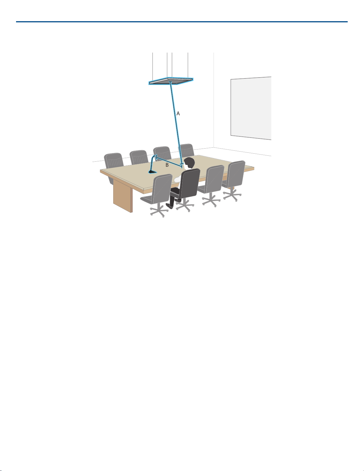
B = Distance between cardioid microphone and talker
B
A
Shure IncorporatedMXA910 Ceiling Array Microphone
In this example, the acoustic performance of the array microphone mounted (A) feet from the talker matches the cardioid gooseneck microphone placed at a
distance of (B) feet from the talker.
FyreWrap®Fire Protective Wrap System Installation
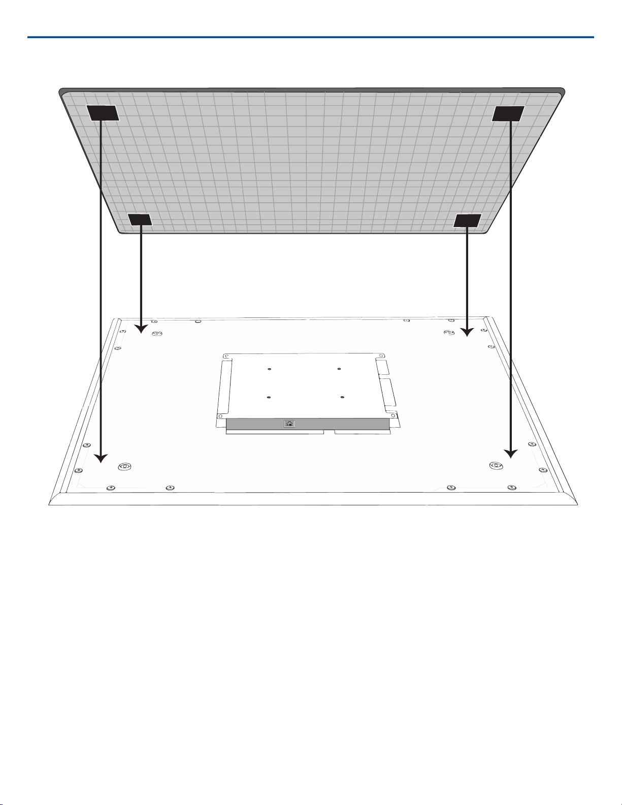
The FyreWrap®fire protective wrap system included with the Microflex®Advance™ MXA910 ceiling array microphone must be installed to meet the UL 2043
plenum rating (suitable for air handling spaces).
Installation
1. Make sure the microphone surface is clean to ensure proper adhesion
2. Remove the paper backing from the 4 adhesive pads on the fire wrap system
3. Align the fire wrap system over the microphone and secure it by applying gentle pressure over the adhesive pads
Note: make sure to leave enough space to install the Ethernet cable and safety tether (if required).
15/572017/10/18
Page 16
Shure IncorporatedMXA910 Ceiling Array Microphone
2017/10/1816/57
Page 17
Shure IncorporatedMXA910 Ceiling Array Microphone
Installing the Array Microphone
Before you begin:
• Remove the protective plastic cover from the microphone
• Verify the ceiling tile size matches the appropriate model variation
• If using the optional junction box or adapter accessories, install them on the microphone prior to ceiling installation
Model Variations
ColorCeiling Grid SizeModel
Black2 x 2 ft (60.9 x 60.9 cm)MXA910B
White2 x 2 ft (60.9 x 60.9 cm)MXA910W
Aluminum2 x 2 ft (60.9 x 60.9 cm)MXA910AL
Black60 x 60 cm (23.6 x 23.6 in)MXA910B-60CM
White60 x 60 cm (23.6 x 23.6 in)MXA910W-60CM
Aluminum60 x 60 cm (23.6 x 23.6 in)MXA910AL-60CM
---25 mm expander fits onto 60 cm model, for 62.5 x 62.5 cm installationA910-25MM (Adapter)
------A910-JB (Junction box accessory)
Note: see product specifications for array microphone dimensions.
Ceiling Tile Mounting
The array microphone mounts directly in a ceiling tile grid. The microphone is available in two sizes, with an optional adapter kit also available to provide solutions
for the most common ceiling tile sizes.
IMPORTANT: Do not install the 60 cm model into a 2 ft (609.6 mm) ceiling grid.
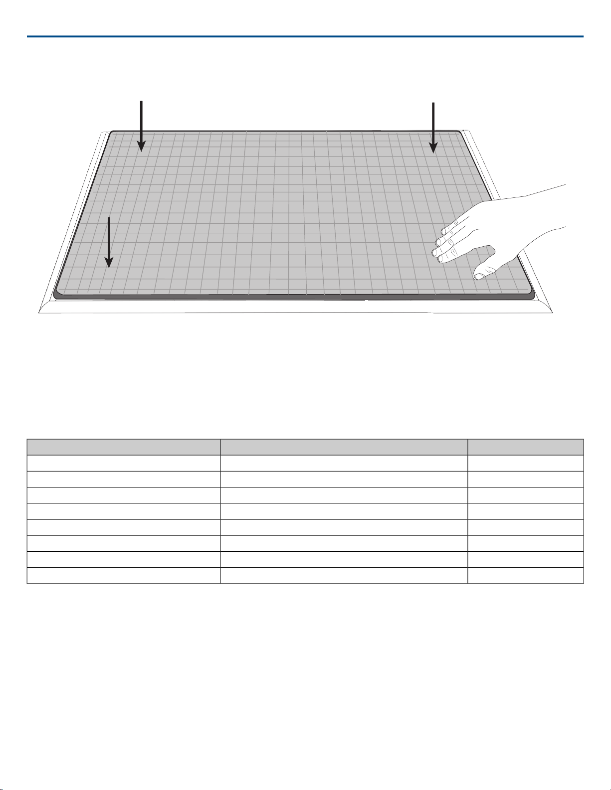
Rubber Scratch Protectors
Optional: Before installing the microphone into the ceiling, attach the included rubber pads on the corners of the microphone to prevent scratching.
17/572017/10/18
Page 18
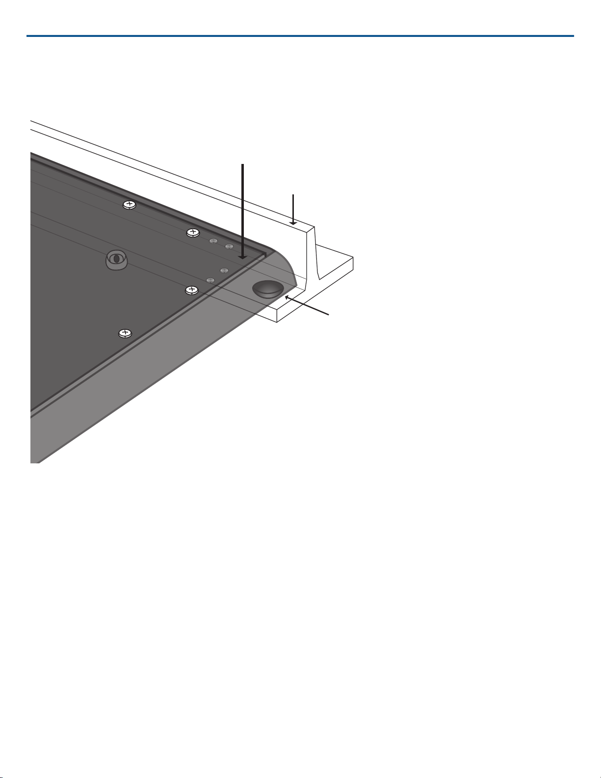
Ceiling Grid Runner
Rubber Pad
Array Microphone
Shure IncorporatedMXA910 Ceiling Array Microphone
Installation
1. Remove the tile from the ceiling grid where the array microphone will be installed.
2. Run the Ethernet cable above the ceiling grid and through the opening in the ceiling.
Note: An optional junction box accessory (model A910-JB) mounts on the microphone to directly connect conduit.
3. Plug the Ethernet cable into the array microphone output.
4. Install the microphone into the ceiling grid.
2017/10/1818/57
Page 19
Shure IncorporatedMXA910 Ceiling Array Microphone
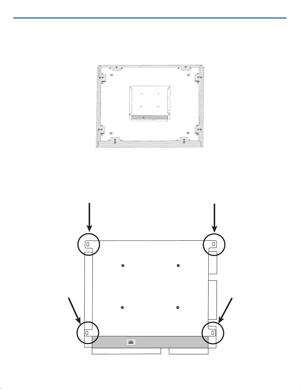
Using the Adapter (625 mm Tile Size)
For ceiling grids which measure 625 x 625 mm, attach the adapter to the array microphone and then follow the ceiling tile mounting instructions.
Note: Only for use with the 60 x 60 cm model
Screw the adapter pieces on as shown, using 2 screws per side.
Other Ceiling Tile Sizes
Mounting the microphone in a grid of a different size requires using a suspension mount option or modifying the ceiling grid.
Safety Tether
19/572017/10/18
Page 20
Shure IncorporatedMXA910 Ceiling Array Microphone
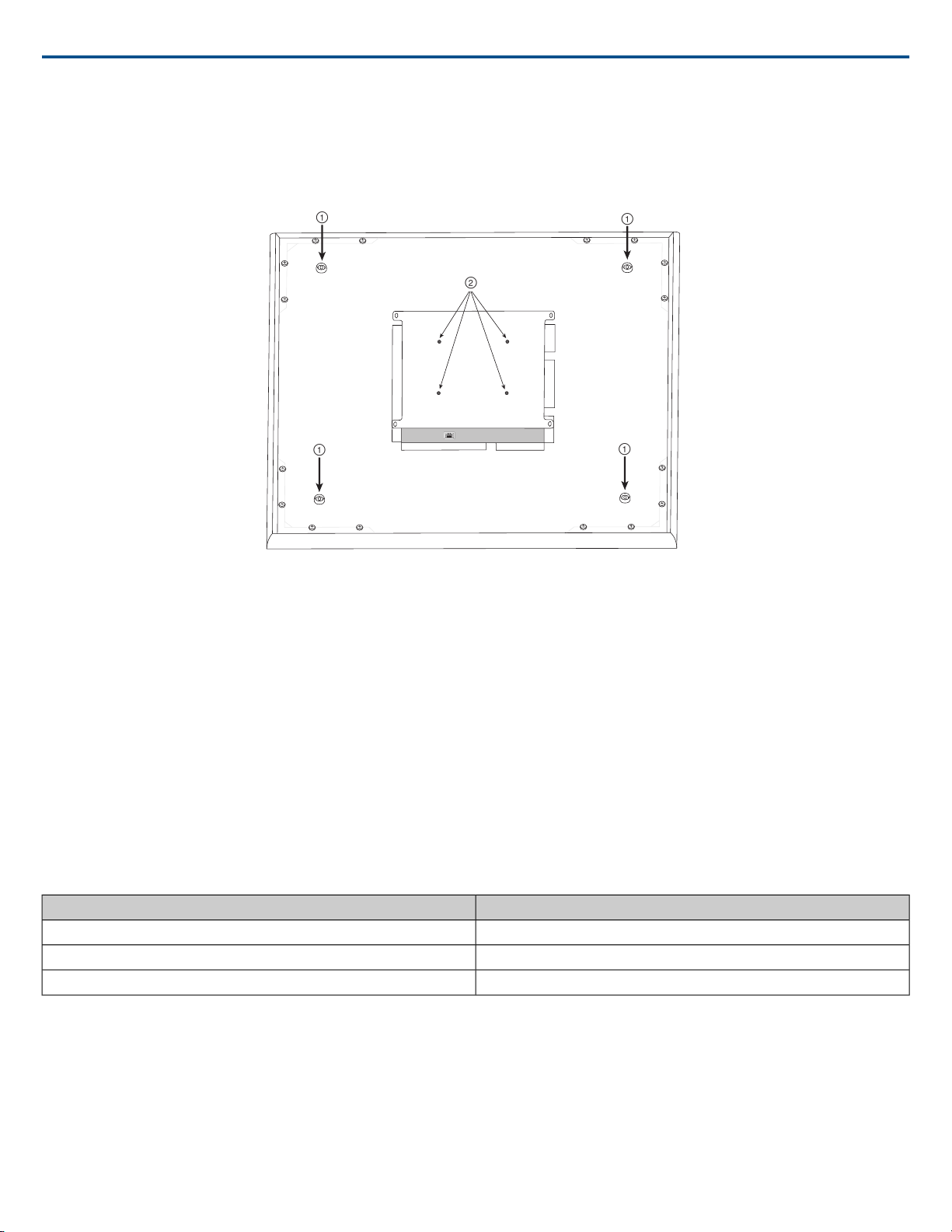
Attach a safety tether between the building structure and one of the tie-off points on the back panel of the microphone. This safety measure prevents the microphone
from falling in an emergency situation. Make sure there is no tension on the safety tether to ensure the microphone is resting properly in the ceiling grid.
Important: Follow local regulations when attaching the safety tether.
Suspension Mounting
① Wire Suspension Hanging Points (4 mm hole size)
② VESA Mounting Holes
4-point Wire Suspension
Secure the microphone to the ceiling using braided metal cable or other high-strength wire. Use the 4 integrated hanging points on the back of the microphone
to securely attach the cable. The hole size in the hanging points is 4 mm (0.15 in).
VESA Standardized Mounting
The rear plate on the microphone has 4 threaded holes for attaching the microphone to a VESA mounting device. The mounting holes follow the VESA MIS-D
standard:
• Screw specification: M4 thread (Microphone threaded hole depth = 9.15 mm)
• Hole spacing: 100 mm (square)
Cable Management
To keep the Ethernet cable out of view, use the appropriate method based on the installation type.
Note: If using conduit to contain the cable, the optional junction box accessory (model A910-JB) mounts directly to the rear panel of the microphone.
Cable SolutionInstallation
Run the cable above the ceiling gridCeiling tile
Guide the cable through the pole to run it above the ceiling gridVESA (pole mounting)
Use cable ties to attach the CAT5 cable along one of the hanging wires4-point wire suspension
Painting Components
The grille and frame of the array microphone can be painted to blend in with room design. Some basic disassembly is required for painting.
Step 1: Removing the Frame and Grille
1. Remove the screws that hold the main assembly on the frame (6 screws per side). There are washers between these screws and the rear panel.
Important: Do not remove the screws that are farthest in the corner and recessed into the panel (see graphic).
2. Carefully lift the assembly out of the frame.
2017/10/1820/57
Page 21
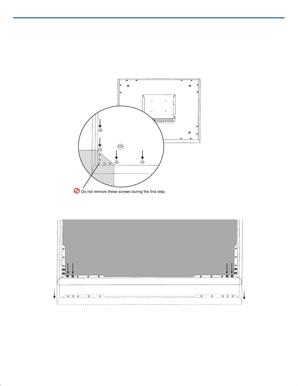
3. Remove the gray plastic LED lightpipe. Leave the black plastic guide in place.
Do not remove these screws during
the first step
4. Remove all 4 screws from one side of the frame (see image).
5. Remove the side of the frame.
6. Slide the flat grille out of the frame for easy removal of the foam piece.
7. Carefully remove the foam piece from the grille. Pull from the edges, where it is attached with hook and loop fastener strips.
Important: Do not paint the foam.
Shure IncorporatedMXA910 Ceiling Array Microphone
(1.1) Removing the screws to detach the main assembly
(1.4 - 1.5) Removing screws and detaching one side of the frame
Step 2: Masking and Painting
1. Use masking tape to cover the entire extrusion that runs along the inside of the frame. This ensures that the necessary metal pieces make contact when
reassembled.
2. Use masking tape to cover the hook-and-loop fastener strips on the grille.
3. Paint the frame and grille section and allow it to completely dry before reassembling. Do not paint any part of the main assembly.
21/572017/10/18
Page 22
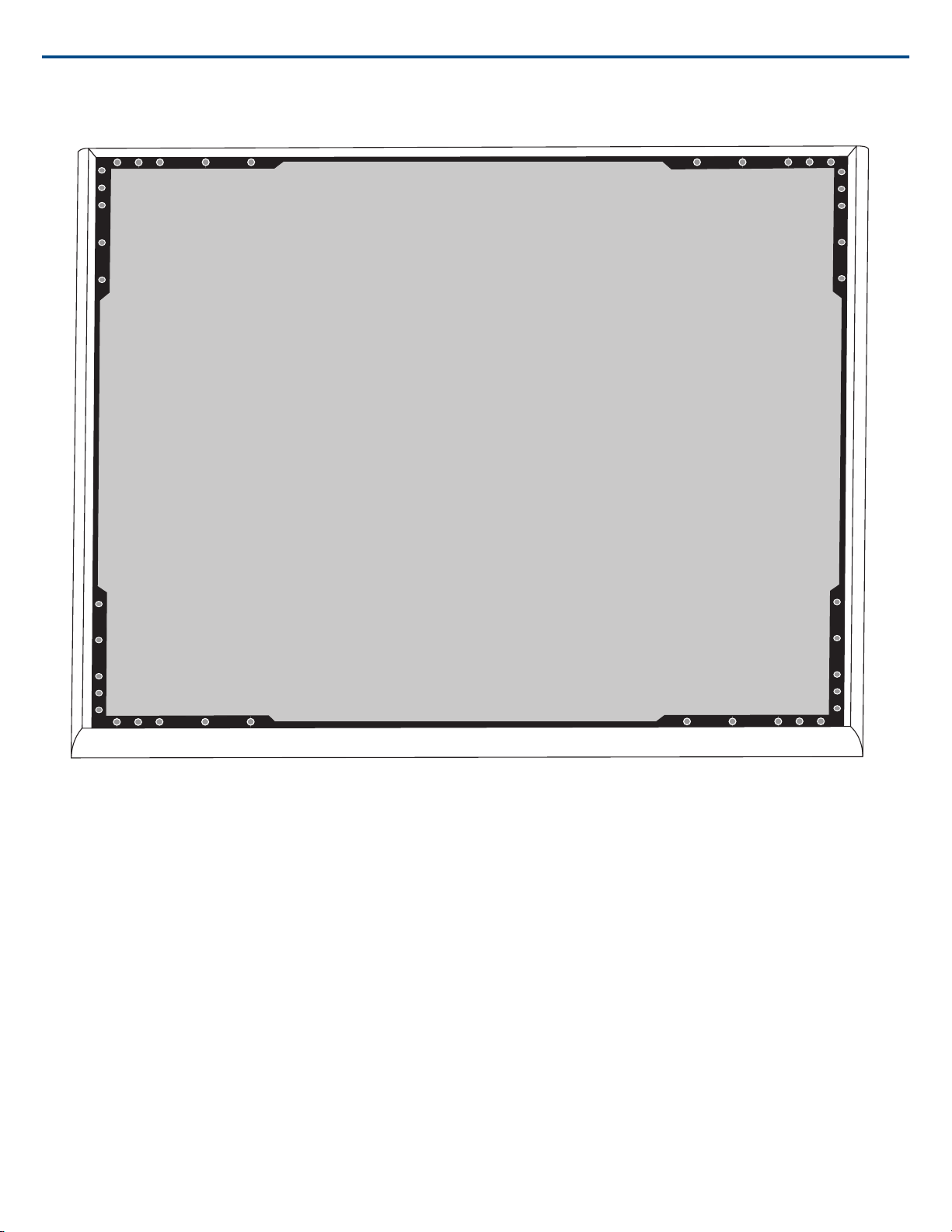
Shure IncorporatedMXA910 Ceiling Array Microphone
(2.1) Masking off the extrusion (highlighted in black)
Step 3: Reassembly
1. Secure the foam piece with the hook-and-loop fastener strips around the edges.
2. Slide the grille back into the frame.
3. Attach the remaining side of the frame and secure it with the 4 screws.
4. Attach the LED lightpipe into the black plastic guide piece.
5. Align the LED with the lightpipe and put the assembly back in place on the frame.
Note: The label on the assembly is placed on the corner that corresponds to the LED. Use it for reference to ensure proper orientation during reassembly.
6. Install the screws (6 per side) to secure the main assembly to the frame. Do not over-tighten.
Installing the Junction Box Accessory
The A910-JB junction box mounts on the microphone, enabling conduit connections for cable runs. Refer to local building codes and regulations to determine
if the junction box is necessary. There are three punch-out sections on the junction box for attaching conduit.
2017/10/1822/57
Page 23
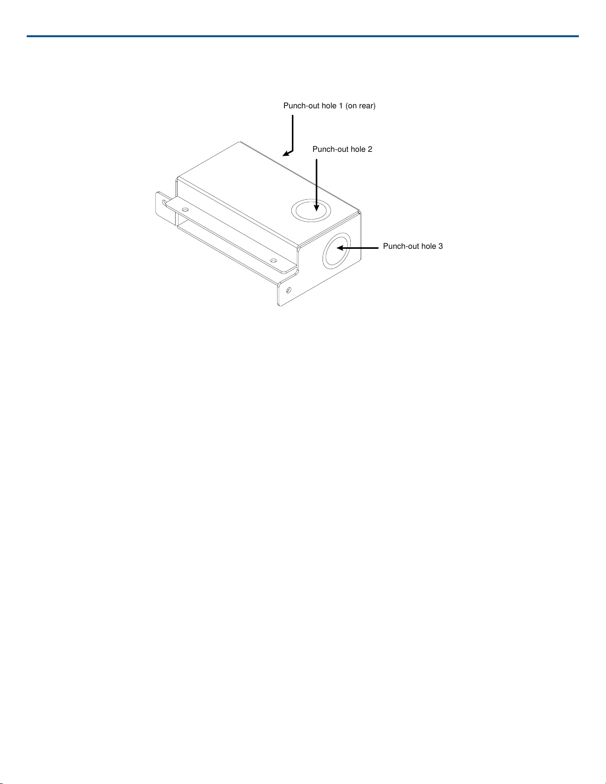
Punch-out hole 1 (on rear)
Punch-out hole 2
Punch-out hole 3
Shure IncorporatedMXA910 Ceiling Array Microphone
Important: Punch out the necessary holes in the junction box prior to installing it onto the microphone.
To install:
1. Remove the 4 screws from the microphone as shown.
23/572017/10/18
Page 24
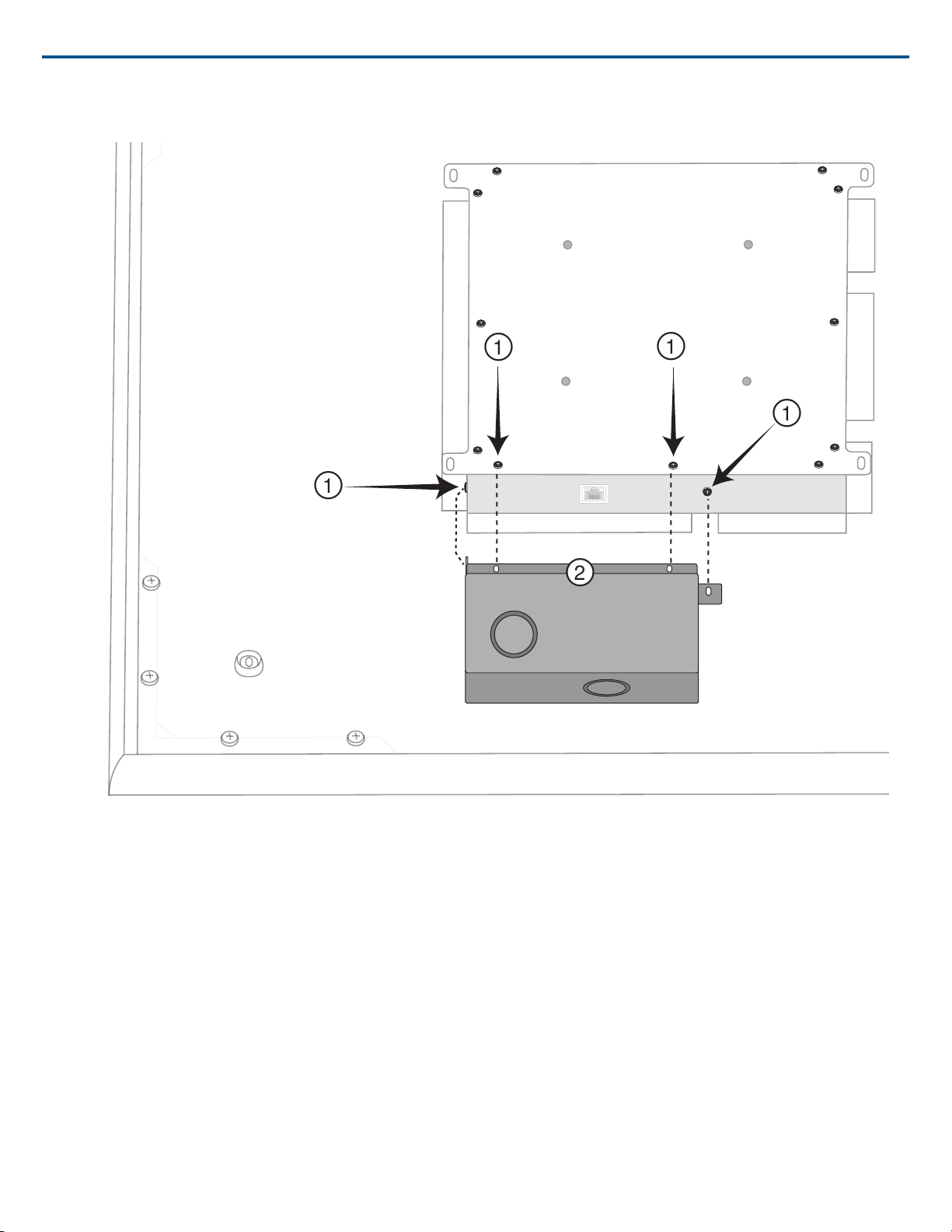
2. Align the junction box with the screw holes. If possible, plug the network cable into the microphone before securing the junction box.
Shure IncorporatedMXA910 Ceiling Array Microphone
3. Install the 4 screws to secure the junction box on the microphone.
2017/10/1824/57
Page 25
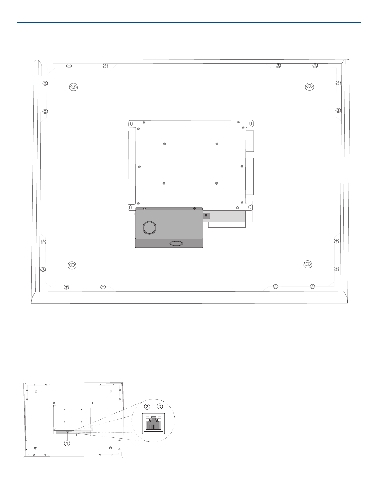
Shure IncorporatedMXA910 Ceiling Array Microphone
Hardware
Network Ethernet Port
The network port carries all audio, power, and control data. It is located on
the back panel as shown.
① Network Port
RJ-45 jack for network connection.
② Network Status LED (Green)
Off = no network link
On = network link established
Flashing = network link active
③ Network Speed LED (Amber)
Off = 10/100 Mbps
On = 1 Gbps
LED Light Bar
LED Light Bar
The LED on the microphone indicates whether the microphone is active or
muted, identifies the hardware, and provides confirmation of firmware updates.
25/572017/10/18
Page 26
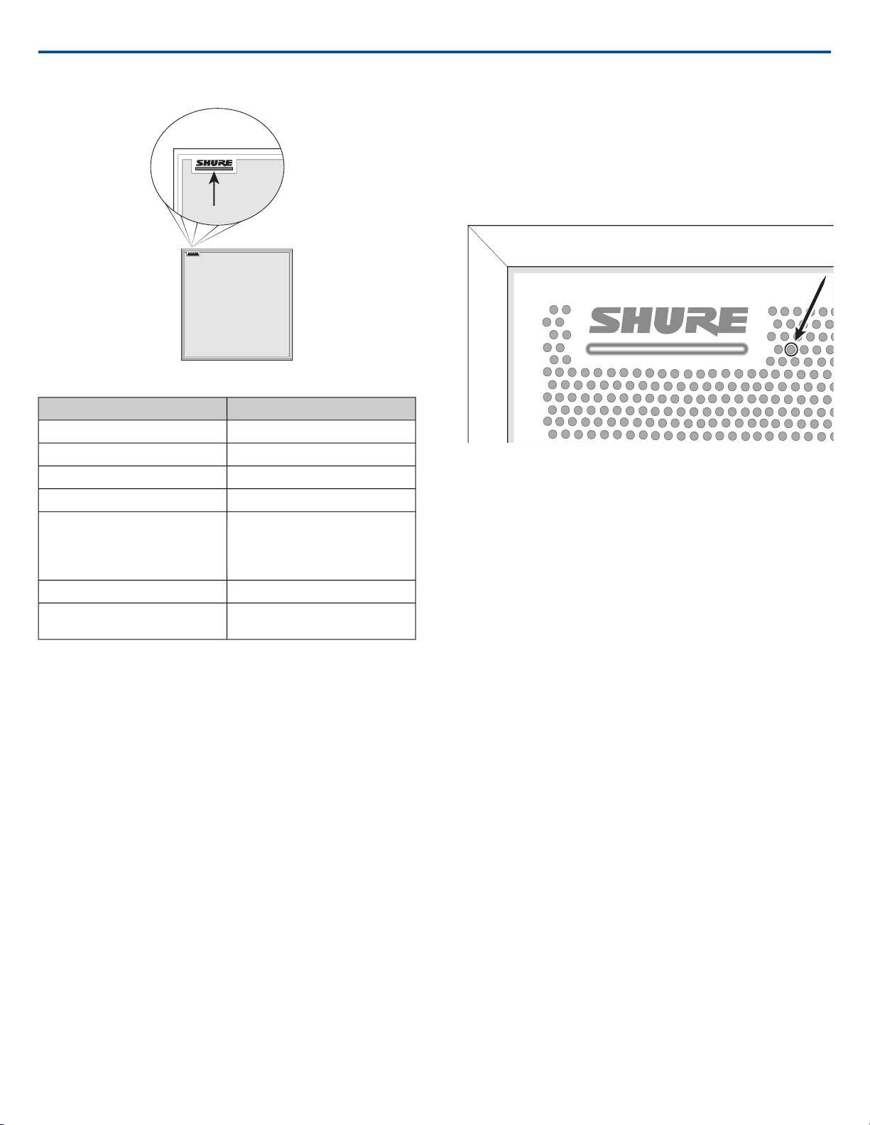
LED Behavior / ColorMicrophone Status
Green (solid)Active
Red (solid)Mute
Green (flashing)Hardware identification
Green (progresses along bar)Firmware update in progress
Network reset: Red (progresses
Reset
Device power-up
Note: When the LED is disabled, the LED still illuminates while the device
is powering up and when an error state occurs.
Factory reset: Triggers device pow-
Red (split, alternate flashing)Error
Multi-color flash, Blue (moves quickly
along bar)
er-up
back and forth across bar)
Customizing Lighting Settings
Custom LED brightness, colors, and behaviors are assignable in the control
software. They can also be controlled through an external control system:
1. Open the Configuration tab
2. Select Light Bar
Mute LED Behavior
The lighting for mute and active microphone states is configurable to match
the behavior of other devices in conference rooms. In the LIGHT BAR
PROPERTIES menu, use the drop-down menus to select LED settings.
Shure IncorporatedMXA910 Ceiling Array Microphone
Reset Button
Reset Button
The hardware reset button is located inside a grille hole and can be pushed
with a paperclip or other small tool. The hole is identified with a gray circle.
When looking at the Shure logo, it is the second hole in the fourth row from
the top.
Reset Modes
Network reset (press button for 4-8 seconds)
Resets all Shure control and audio network IP settings to factory defaults
Full factory reset (press button for longer than 8 seconds)
Restores all network and web application settings to the factory defaults.
Software Reset Options
To simply revert settings without a complete hardware reset, use one of the
following options:
Reboot Device:In the web application (settings > factory reset), there is a
Reboot Device button, which simply power-cycles the device as if it were
unplugged from the network. All settings are retained when the device is rebooted.
Default Settings: To revert audio settings back to the factory configuration
(excluding Device Name, IP Settings, and Passwords), select Load Preset
and choose the default settings preset.
Power Over Ethernet (PoE)
Power Over Ethernet
This device requires PoE to operate. It is compatible with both Class 0 and
Class 3 PoE sources.
Power over Ethernet is delivered in one of the following ways:
• A network switch that provides PoE
• A PoE injector device
Dimming and Disabling
To dim or turn off the LED, use the drop-down menu in the Light Bar configuration screen.
2017/10/1826/57
Page 27

Shure IncorporatedMXA910 Ceiling Array Microphone
Software Installation, Management, and Security
Accessing the Web Application
The Shure Web Server Discovery application finds all Shure devices on the network that feature a web-based GUI. Follow these steps to install the software
and access the web application:
① Install the Shure Discovery application
Download and install the Shure Discovery application from www.shure.com. This automatically installs the required Bonjour device discovery tool on the computer.
② Connect the network
Ensure the computer and the hardware are on the same network.
③ Launch the Discovery application
The app displays all Shure devices that feature a GUI.
④ Identify the hardware
Double-click on a device to open its GUI in a web browser.
⑤ Bookmark the device's web application (recommended)
Bookmark the device's DNS name to access the GUI without the Shure Discovery app.
Web Application Browser Compatibility
The web application is compatible with all HTML5-supported browsers. To ensure the best performance, disabling hardware acceleration and unused plug-ins
is recommended.
Accessing the Web Application without the Discovery App
If the Discovery application is not installed, the web application can be accessed by typing the DNS name into an internet browser. The DNS name is derived
from model of the unit, in combination with the last three bytes (six digits) of the MAC address, and ending in .local.
Format Example: If the MAC address of a unit is 00:0E:DD:AA:BB:CC, then the link is written as follows:
MXA910: http://MXA910-aabbcc.local
Using A Password
All settings are configurable by default. To protect settings with a password, open the Settings menu and select the General tab. In this screen, passwords can
be created or changed.
Once a password has been set, a Read-Only option appears on the log-in screen. In Read-Only mode, device parameters can be viewed, but not edited. Device
identification remains active.
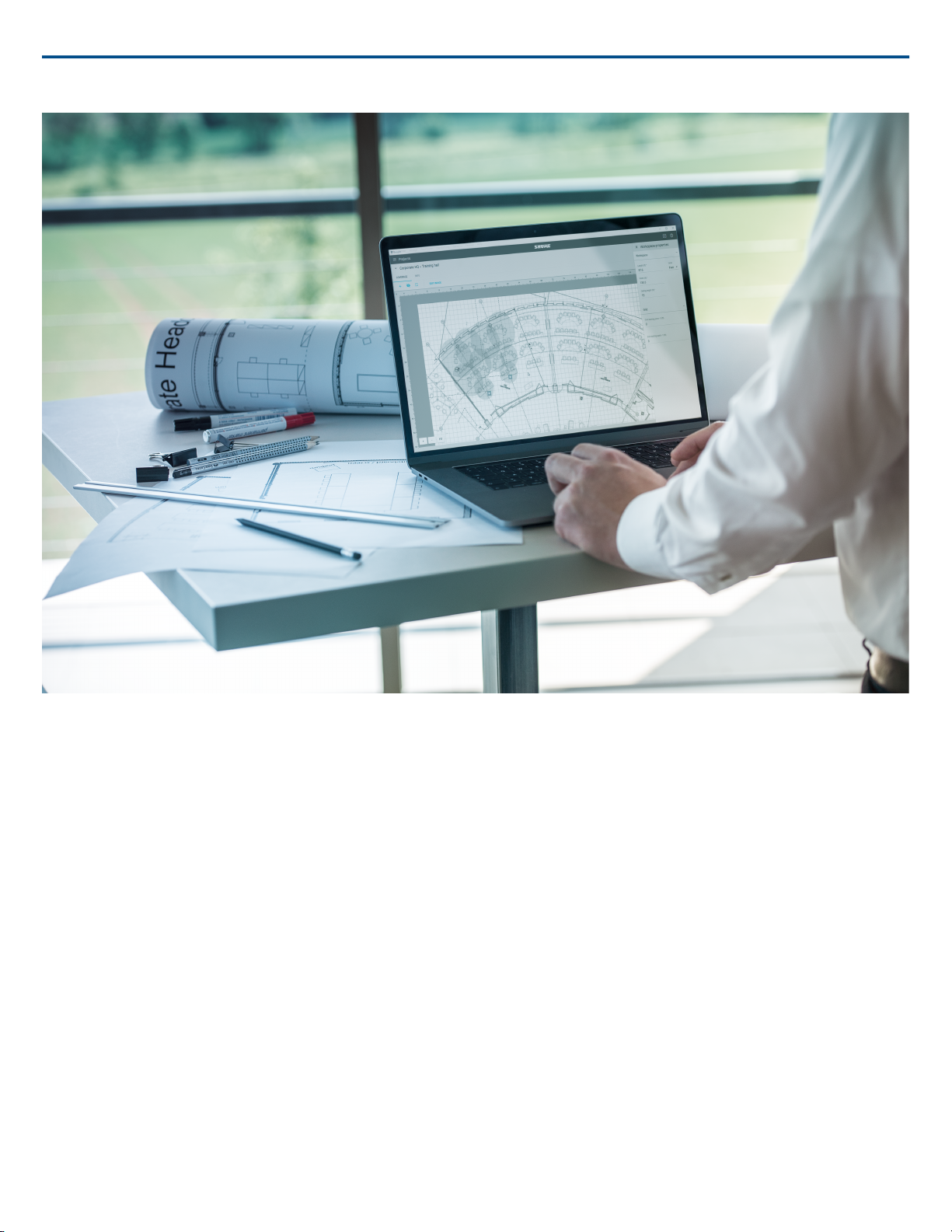
Designer System Configuration Software
Designer System Configuration Software enables integrators and system planners to design accurate audio coverage for installations using multiple Shure
MXA910 Ceiling Array microphones. Accurately model meeting and presentation spaces by importing a floorplan, scaling your room, and positioning devices
around participant areas.
Designer allows you to edit coverage parameters before the microphone is installed: enter the microphone and ceiling height, add channels, and create accurate
coverage areas. After completing your design, simply export the device presets to upload and fine-tune on site.
27/572017/10/18
Page 28
Shure IncorporatedMXA910 Ceiling Array Microphone
Features
• Design audio coverage for installations using Shure MXA 910 Ceiling Array Microphones
• Add multiple devices to create larger and more complex installations
• Easily export device presets for individual locations or full projects
• Organize installations for multiple rooms, buildings, and clients
• Save time and travel expenses by importing a floorplan and using virtual devices to design your system
• Accurately scale floor plans and reference photos for precise device setup
• Share project files with other Designer users so that multiple people can work on a project
Downloading the Application
Download the application and learn more at www.shure.com/designer.
Firmware Updates
Firmware is embedded software in each component that controls functionality. Periodically, new versions of firmware are developed to incorporate additional
features and enhancements. To take advantage of design improvements, new versions of the firmware can be uploaded and installed using the Shure Update
Utility. Software is available for download from http://www.shure.com.
Important: When components are connected through the Shure MXW Audio Network Interface, their firmware must be updated on one device at a time prior
to updating the MXW Audio Network Interface firmware. Attempting to update all devices at once will cause the interface to reboot after its firmware is updated,
and the connection to other networked components will be lost.
Perform the following steps to update the firmware:
CAUTION! Ensure the device has a stable network connection during the update. Do not turn off the device until the update is complete.
1. Connect the device and computer to the same network (set to the same subnet).
2. Download Shure Update Utility app and install it.
3. Open the application.
2017/10/1828/57
Page 29

Shure IncorporatedMXA910 Ceiling Array Microphone
4. Click Check For Updates... button to view new firmware versions available for download.
5. Select the desired firmware and press Downloadto download it to the Firmware Library.
6. From the Update Devices tab, select the new firmware and press Send Updates... to begin the firmware update, which overwrites the existing firmware on
the device.
Firmware Release Requirements
All devices comprise a network with multiple communications protocols that work together to ensure proper operation. The recommended best practice is that
all devices are on an identical release. To view the firmware version of each device on the network, open the component user interface, and look under Settings>About.
The format for Shure device’s firmware is MAJOR.MINOR.PATCH. (Ex. 1.6.2 where 1 is the Major firmware level, 6 is the Minor firmware level, and 2 is the
Patch firmware level.) At minimum, devices that operate on the same subnet should have identical MAJOR and MINOR release numbers.
• Devices of different MAJOR releases are not compatible.
• Differences in the PATCH firmware release level may introduce undesired inconsistencies.
Microphone Configuration
Software Overview
Software Workflow
The web application is accessed through a web browser, from a computer on the same network. It allows administrators and technicians to control:
Coverage: Adjust lobe width and location, select templates, save or load presets, customize light bar settings, and run automatic setup.
Channels: Adjust and monitor channel levels, mute channels or channel groups, configure automix settings, and adjust equalizer settings.
Settings: Control network IP settings, device name, passwords, languages, firmware identification, and device reset.
Software Workflow Basics
Think of each lobe as an individual microphone. If there were 8 microphones on the table, each one could be physically moved according to seating arrangements,
and would be plugged into a mixer with independent gain and channel controls. With the Microflex Advance Ceiling Array Microphone, the web application delivers control over the physical coverage and audio channel settings, with user presets to quickly switch between configurations. Each lobe is moved according
to seating arrangements, with three width settings to change the size of the coverage area. Independent mixer channels control the level and audio properties
for each lobe.
29/572017/10/18
Page 30
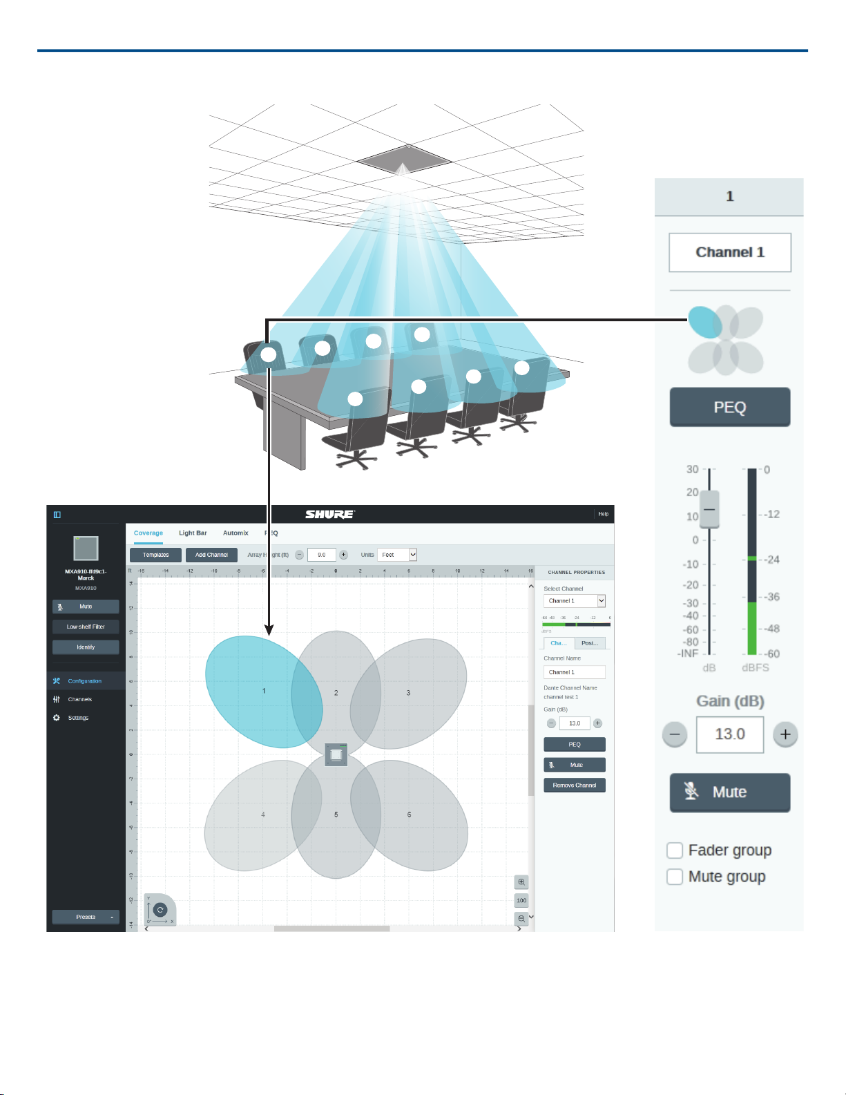
௦
Coverage View
Channels View
Shure IncorporatedMXA910 Ceiling Array Microphone
Each lobe is represented graphically and can be dragged into place. A corresponding mixer channel provides control over audio settings for each lobe.
Configuring Microphone Coverage
Select the Coverage section inside the Configuration tab to access the coverage configuration tools.
Step 1: Set Microphone Properties
1. Set the Units to feet or meters, according to your preference.
2017/10/1830/57
Page 31

Shure IncorporatedMXA910 Ceiling Array Microphone
2. Enter a value for the microphone height. This distance is between the floor and the microphone height.
3. If necessary, use the orientation tool at the bottom of the workspace to rotate the configuration view to match the installer's perspective. Use the degree
value or the microphone LED in the workspace to confirm the position.
Step 2: Select a Template
Select a template that is the closest match to the seating scenario.
Step 3: Set Coverage
Lobes can be automatically or manually positioned. The Auto Position feature detects sound from a specific area when the microphone has already been installed.
Manual positioning is useful for designers, when the room has been specified but the microphone has not yet been installed.
Automatic Positioning
Automatic positioning determines the talker position (X/Y values) and the talker height through a simple soundcheck.
1. Select a channel to position the lobe.
2. Choose Auto Position in the Channel Properties section to start the process.
3. Follow the directions provided for each step presented in the software.
4. Repeat for each channel as needed.
Best Practices
• Verify that the microphone height has been accurately entered in the Array Properties.
• Use speech as the sound source. Do not use test tones.
• Eliminate noise sources in the room if possible, such as projectors or fans.
• For the best acoustics, talkers should not be directly against a wall or in a corner, as acoustic reflections can reduce aiming accuracy.
• Speak from the exact location where the lobe should be positioned. It is important to match the height (sitting or standing), as talker height is determined
through automatic positioning.
• If a lobe needs to cover an area with multiple talkers, talk from the center of the region. Manual adjustments may be necessary after the lobe is positioned
to ensure the entire area is covered.
Manual Positioning
1. Move lobes to cover the appropriate areas.
⁃ Lobes are independently selectable and can be moved anywhere within the maximum allowed coverage area. If dragged outside of this region, lobes
turn red and revert back to the last acceptable position.
⁃ Lobes can be positioned in two ways: drag them into place, or manually enter a distance from the microphone. Distance values are X and Y along the
grid, with the microphone centered at 0.
⁃ Use the grid to measure the precise placement of the lobe.
2. Enter the talker height by selecting a lobe and providing the value in the Channel Properties. This ensures accurate aiming.
Using the Reference Grid
The grid provides a frame of reference to show distances relative to the center of the microphone. The selected unit (feet/meters) applies to the grid, so make
sure it has been set appropriately. If the distances between the talkers and the microphone are known, the grid can visually verify that the lobe placement is
correct.
Note: Values to the left of the microphone on the horizontal X-axis, and below the microphone on the vertical Y-axis are measured as negative values. When
the rotate feature is used, the grid values change to match the new perspective.
Adding and Removing Channels
To add channels into the workspace, use the Add Channel button located above the workspace.
To remove a channel, select a lobe and select Remove Channel, located under the Channel Properties. The delete key may also be used to remove the selected
channel.
Step 4: Adjust Lobe Width
Independent width control makes it possible for some lobes to capture individual talkers (narrow), while other lobes cover multiple talkers (wide).
To change a lobe width:
31/572017/10/18
Page 32
55°
45°
35°
6 ft
3.8 ft
5 ft
6.2 ft
Shure IncorporatedMXA910 Ceiling Array Microphone
1. Select Configuration in the web application
2. Select a lobe in the room view to reveal the channel properties menu
3. Choose a channel width setting from the pull-down menu. The width is calculated and displayed, based on the lobe location and ceiling height.
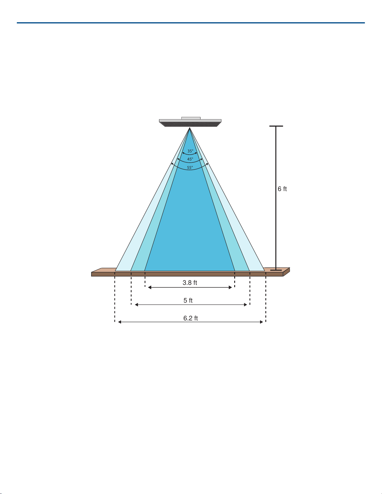
Lobe Width Settings:
• Narrow (35°)
• Medium (45°)
• Wide (55°)
Lobe widths for the three settings with the microphone 6 feet above a table
Adjusting Levels
Gain levels on Microflex®Advance™ microphones must be set for each saved coverage preset to ensure optimized gain structure for all seating scenarios.
Always adjust the levels before making any changes to automix settings to ensure the best performance.
1. Perform a level check for each coverage area, using a typical speech volume. Adjust the faders so the meters are peaking at approximately -20 dBFS.
2. Adjust the equalizer settings to optimize speech intelligibility and minimize noise (such as low-frequency rumble caused by HVAC systems).
3. If equalizer settings cause a significant increase or decrease in levels, make any necessary level adjustments according to step 1.
Parametric Equalizer
Maximize audio quality by adjusting the frequency response with the parametric equalizer.
Common equalizer applications:
• Improve speech intelligibility
• Reduce noise from HVAC systems or video projectors
• Reduce room irregularities
• Adjust frequency response for reinforcement systems
2017/10/1832/57
Page 33
Filters
Frequency
Gain
Q
Width
Shure IncorporatedMXA910 Ceiling Array Microphone
Setting Filter Parameters
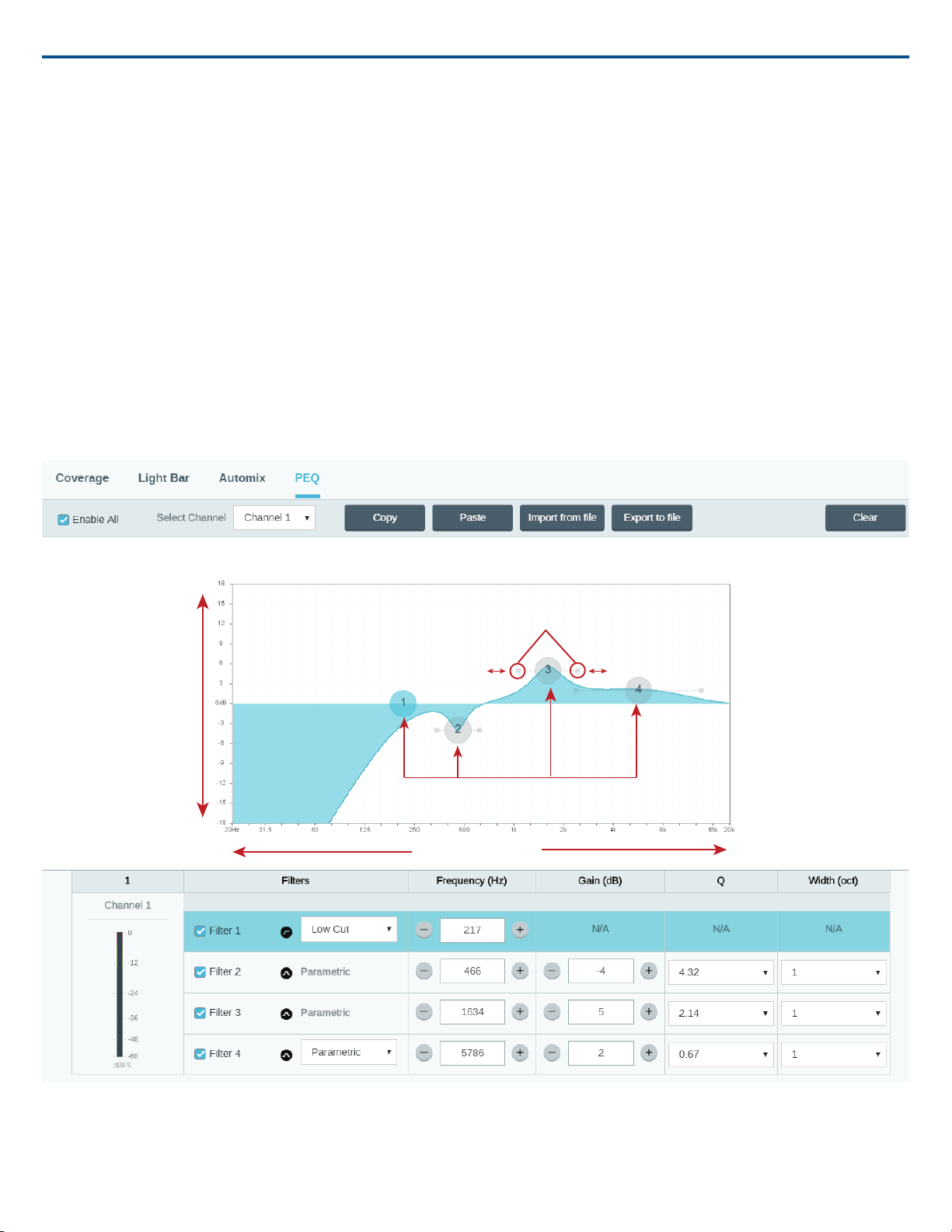
Adjust filter settings by manipulating the icons in the frequency response graph, or by entering numeric values. Disable a filter using the check-box next to the
filter.
Filter Type
Only the first and last band have selectable filter types.
Parametric: Attenuates or boosts the signal within a customizable frequency range
Low Cut: Rolls off the audio signal below the selected frequency
Low Shelf: Attenuates or boosts the audio signal below the selected frequency
High Cut: Rolls off the audio signal above the selected frequency
High Shelf: Attenuates or boosts the audio signal above the selected frequency
Frequency
Select the center frequency of the filter to cut/boost
Gain
Adjusts the level for a specific filter (+/- 30 dB)
Q
Adjusts the range of frequencies affected by the filter. As this value increases, the bandwidth becomes thinner.
Width
Adjusts the range of frequencies affected by the filter. The value is represented in octaves.
Note: the Q and width parameters affect the equalization curve in the same way. The only difference is the way the values are represented.
Copy, Paste, Import, and Export Equalizer Channel Settings
These features make it simple to use effective equalizer settings from a previous installation, or simply accelerate configuration time.
33/572017/10/18
Page 34
Shure IncorporatedMXA910 Ceiling Array Microphone
Copy and Paste
Use to quickly apply the same PEQ setting across multiple channels.
1. Select the channel from the pull-down menu in the PEQ screen.
2. Select Copy
3. In the pull-down menu, select the channel to apply the PEQ setting and select Paste.
Note: Does not apply to MXA310.
Import and Export
Use to save and load PEQ settings from a file on a computer. This is useful for creating a library of reusable configuration files on computers used for system
installation.
Export
Choose a channel to save the PEQ setting, and select Export to file.
Import
Choose a channel to load the PEQ setting, and select Import from file.
When to Use the Channel and Automix Equalizers
Apply Automix EQ to make system-wide changes, such as a treble boost to improve speech clarity. Use Channel EQ to make adjustments to a specific channel.
For example, to reduce unwanted noise picked up by only one channel.
Note: The equalizer can only be assigned to a single channel on the MXA310.
Equalizer Applications
Conferencing room acoustics vary based on room size, shape, and construction materials. Use the guidelines in following table.
Suggested SettingsEQ Application
Add a high shelf filter to boost frequencies greater than 1 kHz by 3-6 dBTreble boost for improved speech intelligibility
Add a low cut filter to attenuate frequencies below 200 HzHVAC noise reduction
Identify the specific frequency range that "excites" the room:
1.Set a narrow Q value
Reduce flutter echoes and sibilance
Reduce hollow, resonant room sound
frequencies between 1 kHz and 6 kHz to pinpoint the range of flutter echoes
minimize the unwanted room sound
Identify the specific frequency range that "excites" the room:
frequencies between 300 Hz and 900 Hz to pinpoint the resonant frequency
minimize the unwanted room sound
2.Increase the gain to between +10 and +15 dB, and then experiment with
or sibilance
3.Reduce the gain at the identified frequency (start between -3 and -6 dB) to
1.Set a narrow Q value
2.Increase the gain to between +10 and +15 dB, and then experiment with
3.Reduce the gain at the identified frequency (start between -3 and -6 dB) to
Custom Presets
Use presets to quickly save and recall settings. Up to 10 presets can be stored on each device to match various seating arrangements. A preset saves all device
settings except for the Device Name, IP Settings, and Passwords. Importing and exporting presets into new installations saves time and improves workflow.
When a preset is selected, the name displays above the preset menu. If changes are made, an asterisk appears next to the name.
Note: Use the default settings preset to revert to the factory configuration (excludes Device Name, IP Settings, and Passwords).
Open the presets menu to reveal preset options:
save as preset:
Saves settings to the device
load preset:
Opens a configuration from the device
import from file:
Downloads a preset file from a computer onto the device. Files may be selected through the browser or dragged into the import window.
2017/10/1834/57
Page 35

Shure IncorporatedMXA910 Ceiling Array Microphone
export to file:
Saves a preset file from the device onto a computer
Mute and Fader Groups
Mute / Fader Groups
Add channels to a Mute group or Fader group to link the corresponding controls together. For example, if channels 1, 2, and 3 are added to a Mute group,
muting any of those individual channels will mute all of the grouped channels.
Automix Channel
This channel automatically mixes the audio from all channels to deliver a convenient, single output. The automix channel is always active. To use it, simply route
the channel in Dante™ Controller to the desired output.
There are two ways to access AUTOMIX settings:
From the configuration screen:
1. Select Configuration
2. Open the AUTOMIX tab
From the channels screen:
1. Select Channels
2. In the AUTOMIX channel, select the AUTOMIX button
Automix Settings
Leave Last Mic On
Keeps the most recently used microphone channel active. The purpose of this feature is to keep natural room sound in the signal so that meeting participants
on the far end know the audio signal has not been interrupted.
Gating Sensitivity
Changes the threshold of the level at which the gate is opened
Off Attenuation
Sets the level of signal reduction when a channel is not active
Hold Time
Sets the duration for which the channel remains open after the level drops below the gate threshold
Maximum Open Channels
Sets the maximum number of simultaneously active channels
Priority
When selected, this channel gate activates regardless of the number of maximum open channels.
Automix Modes
Classic
Classic mode emulates the Shure SCM820 automixer (in its default settings). It is renowned for fast-acting, seamless channel gating and consistent perceived
ambient sound levels. Off-attenuation in this mode is fixed at -20 dB per channel, regardless of the number of open channels.
Smooth
In Smooth mode, Off-attenuation settings for each channel are scaled, depending on the number of open channels. The scaled gain structure helps to reduce
noise when there is a high channel count. When fewer channels are used, the lower off-attenuation provides transparent gating.
Off-attenuation (dB)Number of channels enabled
-52
-83
-104
-125
-136
-147
-158
35/572017/10/18
Page 36
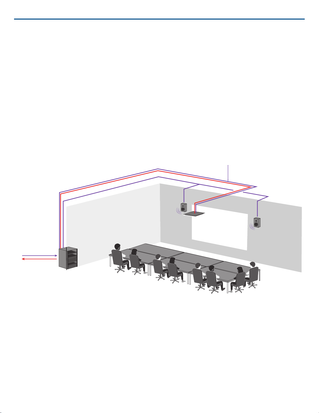
Use the far-end audio as a reference signal to the MXA910 to prevent the loudspeakers from activating the microphone.
Audio in from far end
Audio out to far end
Shure IncorporatedMXA910 Ceiling Array Microphone
Custom
Custom mode provides control over all automixing parameters. This mode is useful when adjustments must be made to one of the preset modes to fit a particular application. If parameters are changed in smooth or classic mode, custom mode automatically activates.
Manual
Manual mode sums all active tracks and sends the summed signal over a single Dante output. This provides the option to route the signal for reinforcement or
recording, without enabling automixing. The settings from the faders in the standard monitoring view apply to the summed output.
Echo Reduction
In audio conferencing, a talker may hear their voice echo as a result of the microphone capturing far-end audio from loudspeakers.
The echo reduction feature prevents the far-end signal from activating the microphone. Ideal for installations in which per-channel DSP echo cancellation is not
within a project budget, echo reduction is highly effective for connecting directly to a computer or video codec which hosts a single-channel echo canceller.
How It Works
An echo reference signal from the far end is routed through Dante Controller software to the microphone's Intellimix processing algorithm. The processor uses
this signal to prevent the microphone from gating on and capturing audio from the loudspeakers.
Enabling Echo Reduction
1. Use Dante Controller software to route the incoming far end audio signal to the Echo Suppression Reference In channel on the MXA910.
2. In the MXA910 web application, enter Configuration> AUTOMIX
3. Enable echo reduction by selecting a strength setting in the pull-down menu. Soft, medium, and hard settings provide far-end attenuation and apply gain to
the reference channel to ensure proper gating.
Note: the off-attenuation setting changes to -56 dB, and the Leave last microphone on setting is set to OFF when echo reduction is enabled.
AES67
AES67 is a networked audio standard that enables communication between hardware components which use different IP audio technologies. This Shure device
supports AES67 for increased compatibility within networked systems for live sound, integrated installations, and broadcast applications.
The following information is critical when transmitting or receiving AES67 signals:
• Update Dante Controller software to the newest available version to ensure the AES67 configuration tab appears
• AES67 must be disabled in Dante Controller before turning encryption on or off in the web application for the Shure device.
• AES67 can not operate when the transmit and receive devices both support Dante. It can only be used when two or more protocols are being used.
2017/10/1836/57
Page 37

Shure IncorporatedMXA910 Ceiling Array Microphone
• Separate Dante and AES67 flows can operate simultaneously. The total number of flows is determined by the maximum flow limit of the device.
Sending Audio from a Shure Device
All AES67 configuration is managed in Dante Controller software. For more information, refer to the Dante Controller user guide.
1. Open the Shure transmitting device in Dante Controller
2. Enable AES67
3. Reboot the Shure device.
4. Create AES67 flows according to the instructions in the Dante Controller user guide.
Receiving Audio from a Device Using a Different Audio Network Protocol
Third-party devices: When the hardware supports SAP, flows are identified in the routing software that the device uses. Otherwise, to receive an AES67 flow,
the AES67 session ID and IP address are required.
Shure devices: The transmitting device must support SAP. In Dante Controller, a transmit device ( appears as an IP address) can be routed like any other Dante
device.
Encryption
Audio is encrypted with the Advanced Encryption Standard ( AES -256), as specified by the US Government National Institute of Standards and Technology
(NIST) publication FIPS-197. Shure devices that support encryption require a passphrase to make a connection. Encryption is not supported with third-party
devices.
To activate encryption:
1. Open the Settings menu and select the General tab.
2. Select the Enable Encryption checkbox.
3. Enter a passphrase. All devices must use the same passphrase to establish an encrypted connection.
Important: For encryption to work:
• Encryption must be universally enabled or disabled on all connected Shure devices
• AES67 must be disabled in Dante Controller to turn encryption on or off. AES67 encryption is currently not supported.
Networking and Dante
Digital Audio Networking
Dantetm digital audio is carried over standard Ethernet and operates using standard Internet Protocols. Dante provides low latency, tight clock synchronization,
and high Quality-of-Service (QoS) to provide reliable audio transport to a variety of Dante devices. Dante audio can coexist safely on the same network as IT
and control data, or can be configured to use a dedicated network.
Switch Recommendations for Dante Networking
In addition to the basic networking requirements, Dante audio networks should use a Gigabit network switch or router with the following features:
• Gigabit ports
• Quality of Service (QoS) with 4 queues
• Diffserv (DSCP) QoS, with strict priority
• Recommended: A managed switch to provide detailed information about the operation of each network link (port speed, error counters, bandwidth used)
Cable Requirements
Always use Cat5E cable or higher.
QoS (Quality of Service) Settings
QoS Settings
QoS settings assign priorities to specific data packets on the network, ensuring reliable audio delivery on larger networks with heavy traffic. This feature is
available on most managed network switches. Although not required, assigning QoS settings is recommended.
Note: Coordinate changes with the network administrator to avoid disrupting service.
To assign QoS values, open the switch interface and use the following table to assign Dante™ -associated queue values.
• Assign the highest possible value (shown as 4 in this example) for time-critical PTP events
• Use descending priority values for each remaining packet.
Table provided courtesy of Audinate
®
37/572017/10/18
Page 38

Shure IncorporatedMXA910 Ceiling Array Microphone
BinaryDecimalHexDSCP LabelUsagePriority
111000560x38CS7Time-critical PTP eventsHigh (4)
101110460x2EEFAudio, PTPMedium (3)
00100080x08CS1(reserved)Low (2)
00000000x00BestEffortOther trafficNone (1)
Note: Switch management may vary by manufacturer and switch type. Consult the manufacturer's product guide for specific configuration details.
For more information on Dante requirements and networking, visit www.audinate.com.
Networking Terminology
PTP (Precision Time Protocol): Used to synchronize clocks on the network
DSCP (Differentiated Services Code Point): Standardized identification method for data used in layer 3 QoS prioritization
Networking
Networking Best Practices
Use the following best practices when setting up a network to ensure reliable communication:
• Always use a "star" network topology by connecting each component directly to the switch or router.
• Connect all Shure networked devices to the same network and set to the same subnet. This applies to all devices that audio signals must be routed between
(managed through Dante Controller). It is also required in order to open the web application for a device.
• Devices on separate networks require an audio processor or conferencing software to carry audio between them. See the system planning and gear requirements section for network setup information and configuration examples.
• Use only 1 DHCP server per network. Disable DHCP addressing on additional servers.
• Power on the switch and DHCP server prior to MXA equipment.
• To expand the network, use multiple Ethernet switches in a star topology.
• All devices must be at the same firmware revision level.
Network Audio and Shure Control Data
Microflex®Advance™ devices transport two types of data over the network: Shure Control and Network Audio.
Shure Control
The Shure Control carries data for the control software operation, firmware updates and 3rd party control systems (AMX, Crestron).
Network Audio
This network carries both the Dante digital audio and the control data for Dante Controller. The network audio requires a wired, gigabit Ethernet connection to
operate.
Device IP Settings
Configure IP
Sets IP mode of the selected network interface:
• Auto (DHCP): For automatic assignment of IP addresses.
• Manual (Static): For Static IP addresses.
IP Settings
View and edit the IP Address, Subnet Mask, and Gateway for each network interface.
MAC Address
The network interface's unique identification.
Configuring IP Settings
IP configurations are managed through the web application. By default, they are set to Automatic (DHCP) mode. DHCP mode enables the devices to accept IP
settings from a DHCP server, or automatically fall back to Link-Local settings when no DHCP is available. IP addresses may also be manually set.
To configure the IP properties, follow these steps:
1. Open the web application.
2. Go to the Settings tab and select Network.
3. Select Auto or Manual. If Auto is used, addresses will be automatically assigned. For Manual setup, follow the instructions on manual configuration.
2017/10/1838/57
Page 39
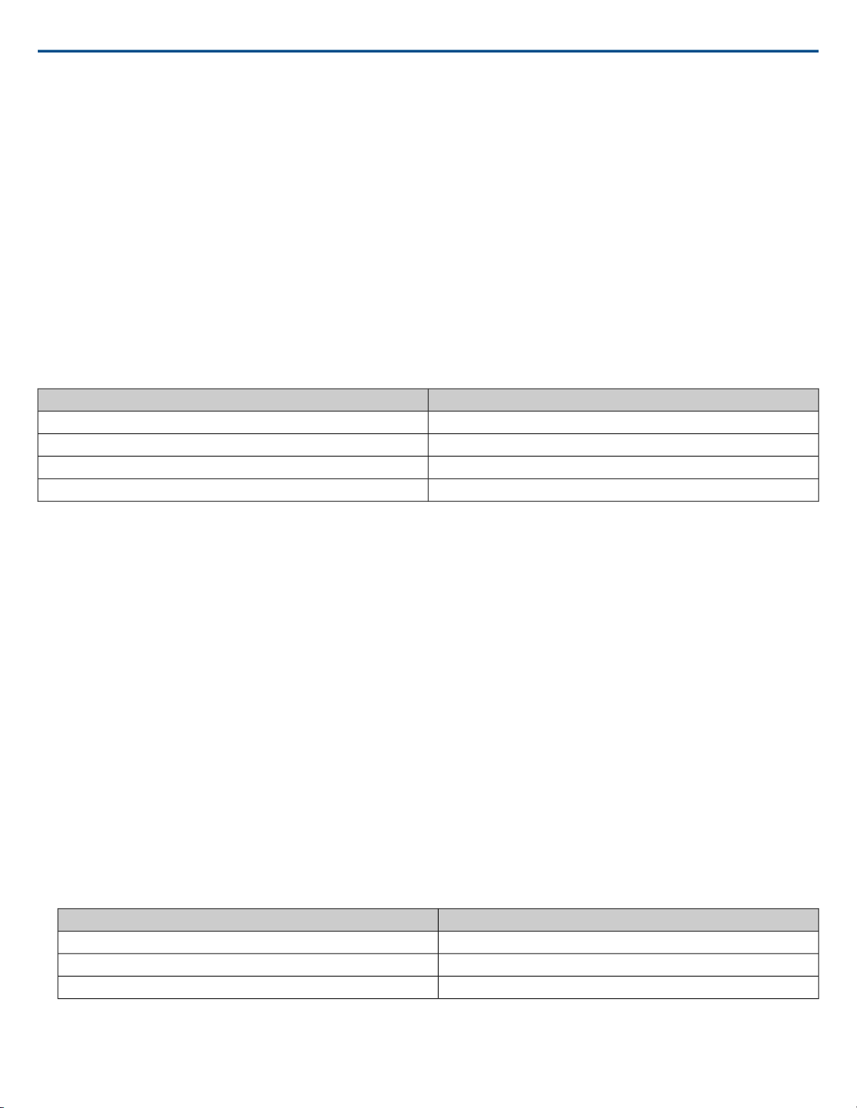
Shure IncorporatedMXA910 Ceiling Array Microphone
Manually Assigning Static IP Address
To manually assign IP addresses, follow these steps:
1. Open the web application.
2. Go to the Settings tab and select Network.
3. Select Manual as the Configure IP setting.
4. Enter the IP settings.
Setting Latency
Latency is the amount of time for a signal to travel across the system to the outputs of a device. To account for variances in latency time between devices and
channels, Dante has a predetermined selection of latency settings. When the same setting is selected, it ensures that all Dante devices on the network are in
sync.
The latency setting for Dante devices should be set according to the number of switches in the network.
Use Audinate's Dante Controller software to change the latency setting.
Latency Recommendations
Maximum Number of SwitchesLatency Setting
30.25 ms
50.5 ms (default)
101 ms
10+2 ms
Operating the Control Software over Wi-Fi
When operating the web application over Wi-Fi, it’s important to set up the wireless router properly for best performance. The system employs several standardbased protocols that rely on multicast. Wi-Fi treats broadcast and multicast packets differently than general packets for backward compatibility reasons. In some
cases, the Wi-Fi router will limit the multicast packet transmission rate to a value that is too slow for web application to properly operate.
Wi-Fi routers typically support 802.11b, 802.11a/g, and/or 802.11n standards. By default, many Wi-Fi routers are configured to allow older 802.11b devices to
operate over the network. In this configuration, these routers will automatically limit the multicast data rates (or sometimes referred to as ‘basic rate’, or ‘management
rate’) to 1-2Mbps.
Note: A Wi-Fi connection can only be used for the control software. Network audio cannot be transmitted over Wi-Fi.
Tip: For larger wireless microphone configurations, it’s recommended to increase the multicast transmission rate to provide adequate bandwidth.
Important: For best performance, use a Wi-Fi router that does not limit the multicast rate to 1-2 Mbps.
Shure recommends the following Wi-Fi router brands:
• Cisco
• Linksys
• Apple
Packet Bridge
Packet bridge enables an external controller to obtain IP information from the control interface of a Shure device. To access the packet bridge, an external
controller must send a query packet over unicast UDP* to port 2203 on the Dante interface of the Shure device.
1. Send a UDP packet with a minimum 1-byte payload .
Note: The maximum accepted payload 140 bytes. Any content is allowed.
2. The Shure device will send a response packet over unicast UDP to the controller, using a destination UDP port identical to the source port of the query
packet. The payload of the response packet follows this format:
ContentBytes
IP address, as 32-bit unsigned integer in network order0-3
Subnet mask, as 32-bit unsigned integer in network order4-7
MAC address, as array of 6 bytes8-13
Note: The Shure device should respond in less than one second on a typical network. If there is no response, try sending the query again after verifying
the destination IP address and port number.
*UDP: User Datagram Protocol
39/572017/10/18
Page 40
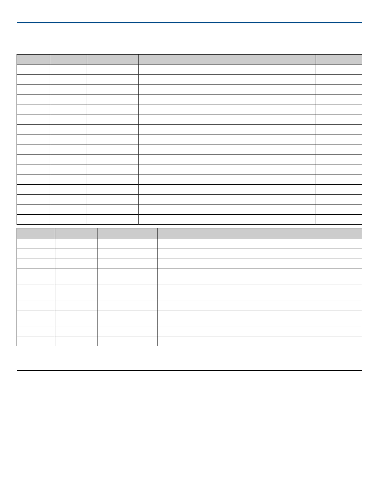
IP Ports and Protocols
427
5353
5568
8427
tcp/udp
udp
udp
udp
Shure IncorporatedMXA910 Ceiling Array Microphone
Factory DefaultDescriptionProtocolTCP/UDPPort
ClosedRequired for firmware updates (otherwise closed)FTPtcp21
ClosedNot supportedSSHtcp22
ClosedStandard console interfaceTelnettcp23
OpenDynamic Host Configuration ProtocolDHCPudp68
OpenRequired to launch embedded web serverHTTPtcp80*
OpenRequired for inter-device communicationSLP†
ClosedNot supportedHTTPStcp443
ClosedNot supportedSNMPtcp161
ClosedNot supportedSNMPtcp162
OpenRequired for 3rd party control stringsASCIItcp2202
OpenRequired for device discoverymDNS†
OpenRequired for inter-device communicationSDT†
PasswordDebug console interfaceTelnettcp8023
OpenRequired for web applicationHTMLtcp8180*
OpenRequired for inter-device communicationMultcast SLP†
OpenRequired for Shure firmware updateTelnettcp64000
DescriptionProtocolTCP/UDPPort
Used by DanteSNMPudp162
4321,
14336-14600
[4440, 4444,
4455]*
[8700-8706,
8800]*
0 1
udp[319-320]*
udp5353
PTP†
Required for packet bridgeCustomudp2203
mDNS†
Dante clocking
Dante audioDanteudp
Dante audio routingDanteudp
Used by Dante
Dante Control and MonitoringDanteudp
Dante ControllerDanteudp8751
Used by DanteDanteudp16000-65536
Using a Third-Party Control System
Control Systems
The microphone receives logic commands over the network. Many parameters controlled through the web application can be controlled through a third party
control system, using the appropriate command string.
Common applications:
• Mute
• LED color and behavior
• Loading presets
• Adjusting levels
0
*These ports must be open on the PC or control system to access the device through a firewall.
1
†These protocols require multicast. Ensure multicast has been correctly configured for your network.
2017/10/1840/57
Page 41
Shure IncorporatedMXA910 Ceiling Array Microphone
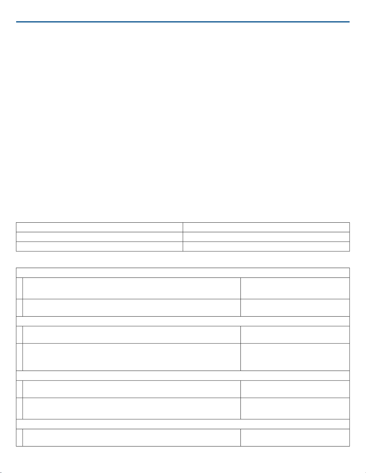
A complete list of command strings is available in the device help or from www.shure.com.
MXA910 Microflex®Advance™ Command Strings
Command Strings
The device is connected via Ethernet to a control system, such as AMX, Crestron or Extron.
Connection: Ethernet (TCP/IP; select “Client” in the AMX/Crestron program)
Port: 2202
Conventions
The device has 4 types of strings:
GET
Finds the status of a parameter. After the AMX/Crestron sends a GET command, the MXA910 responds with a REPORT string
SET
Changes the status of a parameter. After the AMX/Crestron sends a SET command, the MXA910 will respond with a REPORT string to indicate the new value
of the parameter.
REP
When the MXA910 receives a GET or SET command, it will reply with a REPORT command to indicate the status of the parameter. REPORT is also sent by
the device when a parameter is changed on the MXA910 or through the GUI.
SAMPLE
Used for metering audio levels.
All messages sent and received are ASCII. Note that the level indicators and gain indicators are also in ASCII
Most parameters will send a REPORT command when they change. Thus, it is not necessary to constantly query parameters. The MXA910 will send a REPORT
command when any of these parameters change.
The character “x” in all of the following strings represents the channel of the MXA910 and can be ASCII numbers 0 through 9 as in the following table.
Command Strings (Common)
< REP MODEL {yyyyyyyyyyyyyyyyyyyyyyyyyyyyyyyy} >
< REP SERIAL_NUM {yyyyyyyyyyyyyyyyyyyyyyyyyyyyyyyy} >
Command String:
< GET x ALL >
MXA910 Response:
< REP ... >
Command String:
< GET MODEL >
MXA910 Response:
Command String:
< GET SERIAL_NUM >
MXA910 Response:
Command String:
< GET FW_VER >
All channels0
Individual channels1 through 8
Automix output9
Get All
Where x is ASCII channel number: 0 through 9.
Use this command on first power on to update the
status of all parameters.
The MXA910 responds with individual Report
strings for all parameters.
Get Model Number
Where yyyyyyyyyyyyyyyyyyyyyyyyyyyyyyyy is 32
characters of the model number.The MXA910
always responds with a 32 character model
number.
Get Serial Number
Where yyyyyyyyyyyyyyyyyyyyyyyyyyyyyyyy is 32
characters of the serial number.The MXA910
always responds with a 32 character serial number .
Get Firmware Version
41/572017/10/18
Page 42
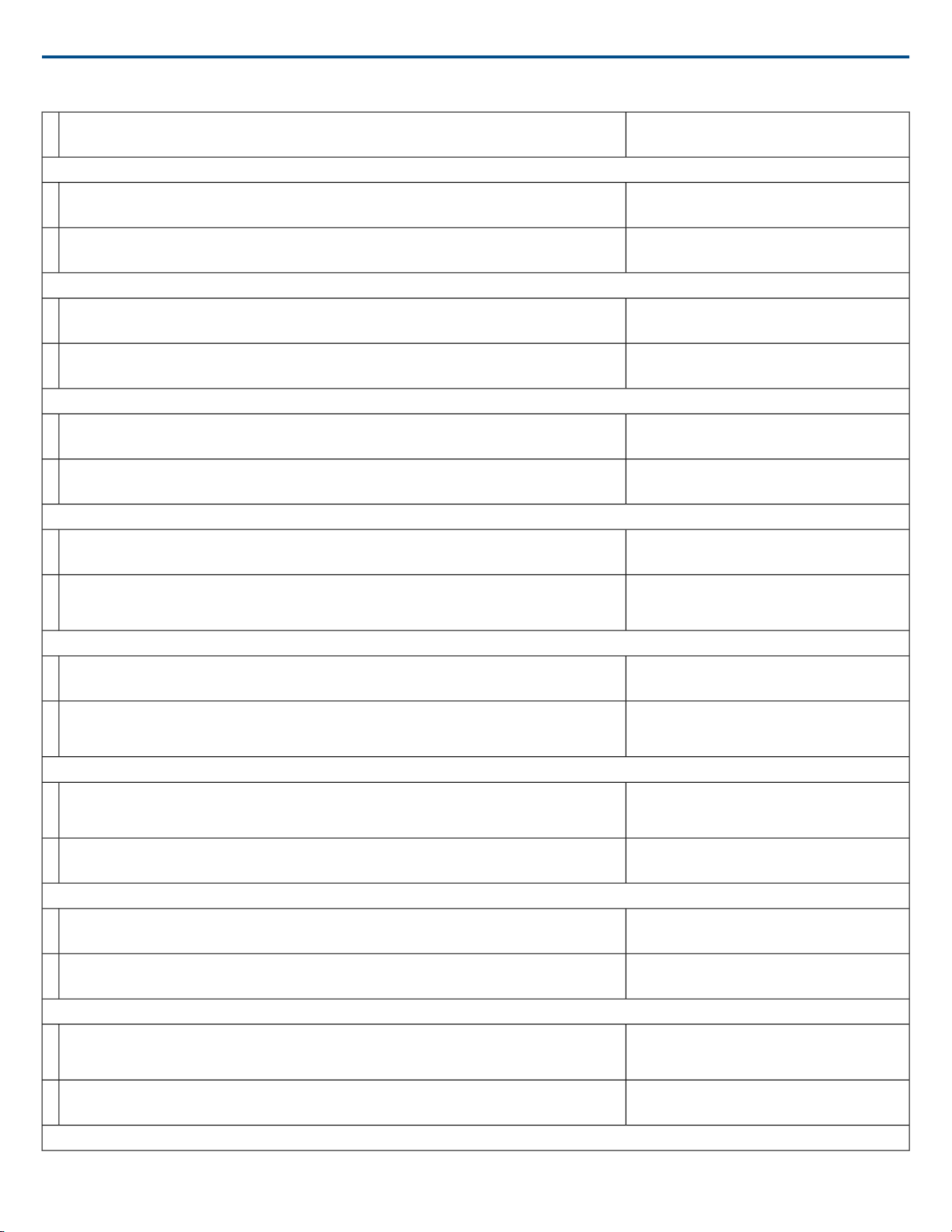
Shure IncorporatedMXA910 Ceiling Array Microphone
MXA910 Response:
< REP FW_VER {yyyyyyyyyyyyyyyyyy} >
Get Audio IP Address
Command String:
< GET IP_ADDR_NET_AUDIO_PRIMARY >
MXA910 Response:
< REP IP_ADDR_NET_AUDIO_PRIMARY {yyyyyyyyyyyyyyy} >
Get Audio Subnet Address
Command String:
< GET IP_SUBNET_NET_AUDIO_PRIMARY >
MXA910 Response:
< REP IP_SUBNET_NET_AUDIO_PRIMARY {yyyyyyyyyyyyyyy} >
Get Audio Gateway Address
Command String:
< GET IP_GATEWAY_NET_AUDIO_PRIMARY >
MXA910 Response:
< REP IP_GATEWAY_NET_AUDIO_PRIMARY {yyyyyyyyyyyyyyy} >
Get Channel Name
Command String:
< GET x CHAN_NAME >
MXA910 Response:
< REP x CHAN_NAME {yyyyyyyyyyyyyyyyyyyyyyyyyyyyyyy} >
Get Device ID
Command String:
< GET DEVICE_ID >
MXA910 Response:
< REP DEVICE_ID {yyyyyyyyyyyyyyyyyyyyyyyyyyyyyyy} >
Get Audio Gain
Command String:
< GET x AUDIO_GAIN_HI_RES >
MXA910 Response:
< REP x AUDIO_GAIN_HI_RES yyyy >
Set Audio Gain
Command String:
< SET x AUDIO_GAIN_HI_RES yyyy >
MXA910 Response:
< REP x AUDIO_GAIN_HI_RES yyyy >
Increase Audio Gain by n dB
Command String:
< SET x AUDIO_GAIN_HI_RES INC nn >
MXA910 Response:
< REP x AUDIO_GAIN_HI_RES yyyy >
Decrease Audio Gain by n dB
Where yyyyyyyyyyyyyyyyyy is 18 characters.The
MXA910 always responds with 18 characters.
Where yyyyyyyyyyyyyyy is a 15 digit IP address.
Where yyyyyyyyyyyyyyy is a 15 digit subnet
address.
Where yyyyyyyyyyyyyyy is a 15 digit gateway
address.
Where x is ASCII channel number: 0 through 9.
Where yyyyyyyyyyyyyyyyyyyyyyyyyyyyyyy is 31
characters of the channel name.The MXA910
always responds with a 31 character name.
The Device ID command does not contain the x
channel character, as it is for the entire device.
Where yyyyyyyyyyyyyyyyyyyyyyyyyyyyyyy is 31
characters of the device ID.The MXA910 always
responds with a 31 character device ID.
Where x is ASCII channel number: 1 through 9.
Channel number 0 (all channels) is not valid for this
command.
Where yyyy takes on the ASCII values of 0000 to
1400. yyyy is in steps of one-tenth of a dB.
Where yyyy takes on the ASCII values of 0000 to
1400. yyyy is in steps of one-tenth of a dB.
Where yyyy takes on the ASCII values of 0000 to
1400.
Where nn is the amount in one-tenth of a dB to
increase the gain. nn can be single digit ( n ),
double digit ( nn ), triple digit ( nnn ).
Where yyyy takes on the ASCII values of 0000 to
1400.
2017/10/1842/57
Page 43
Shure IncorporatedMXA910 Ceiling Array Microphone
Command String:
< SET x AUDIO_GAIN_HI_RES DEC nn >
MXA910 Response:
< REP x AUDIO_GAIN_HI_RES yyyy >
Get Channel Audio Mute
Command String:
< GET x AUDIO_MUTE >
MXA910 Response:
< REP x AUDIO_MUTE ON >
< REP x AUDIO_MUTE OFF >
Mute Channel Audio
Command String:
< SET x AUDIO_MUTE ON >
MXA910 Response:
< REP x AUDIO_MUTE ON >
Unmute Channel Audio
Command String:
< SET x AUDIO_MUTE OFF >
MXA910 Response:
< REP x AUDIO_MUTE OFF >
Toggle Channel Audio Mute
Command String:
< SET x AUDIO_MUTE TOGGLE >
MXA910 Response:
< REP x AUDIO_MUTE ON >
< REP x AUDIO_MUTE OFF >
Get Device Audio Mute
Command String:
< GET DEVICE_AUDIO_MUTE >
MXA910 Response:
< REP DEVICE_AUDIO_MUTE ON >
< REP DEVICE_AUDIO_MUTE OFF >
Mute Device Audio
Command String:
< SET DEVICE_AUDIO_MUTE ON >
MXA910 Response:
< REP DEVICE_AUDIO_MUTE ON >
Unmute Device Audio
Command String:
< SET DEVICE_AUDIO_MUTE OFF >
MXA910 Response:
< REP DEVICE_AUDIO_MUTE OFF >
Toggle Device Audio Mute
Command String:
< SET DEVICE_AUDIO_MUTE TOGGLE >
Where nn is the amount in one-tenth of a dB to
decrease the gain. nn can be single digit ( n ),
double digit ( nn ), triple digit ( nnn ).
Where yyyy takes on the ASCII values of 0000 to
1400.
Where x is ASCII channel number: 0 through 9.
Channel Audio Mute is pre-meter
The MXA910 will respond with one of these strings.
The MXA910 will respond with one of these strings.
Device Audio Mute is post-meter.
The MXA910 will respond with one of these strings.
43/572017/10/18
Page 44
MXA910 Response:
< REP DEVICE_AUDIO_MUTE ON >
< REP DEVICE_AUDIO_MUTE OFF >
Get Output Clip Status
Command String:
< GET x AUDIO_OUT_CLIP_INDICATOR >
MXA910 Response:
< REP x AUDIO_OUT_CLIP_INDICATOR ON >
< REP x AUDIO_OUT_CLIP_INDICATOR OFF >
Flash Lights on Microphone
Command String:
< SET FLASH ON >
< SET FLASH OFF >
MXA910 Response:
< REP FLASH ON >
< REP FLASH OFF >
Get Metering Rate
Command String:
< GET METER_RATE >
Shure IncorporatedMXA910 Ceiling Array Microphone
The MXA910 will respond with one of these strings.
Where x is ASCII channel number: 0 through 9. It
is not necessary to continually send this command.
The MXA910 will send a REPORT message
whenever the status changes.
The MXA910 will respond with one of these strings.
Send one of these commands to the MXA910.The
flash automatically turns off after 30 seconds.
The MXA910 will respond with one of these strings.
MXA910 Response:
< REP METER_RATE sssss >
< SAMPLE aaa bbb ccc ddd eee fff ggg hhh iii >
Turn Metering On
Command String:
< SET METER_RATE sssss >
MXA910 Response:
< REP METER_RATE sssss >
< SAMPLE aaa bbb ccc ddd eee fff ggg hhh iii >
Stop Metering
Command String:
< SET METER_RATE 0 >
Where aaa, bbb, etc is the v alue of the audio level
received and is 000-060.
aaa = output 1
bbb = output 2
ccc = output 3
ddd = output 4
eee = output 5
fff = output 6
ggg = output 7
hhh = output 8
iii = output 9
Where sssss is the metering speed in milliseconds.
Setting sssss=0 turns metering off. Minimum setting
is 100 milliseconds. Metering is off by default.
Where aaa, bbb, etc is the v alue of the audio level
received and is 000-060.
aaa = output 1
bbb = output 2
ccc = output 3
ddd = output 4
eee = output 5
fff = output 6
ggg = output 7
hhh = output 8
iii = output 9
A value of 00000 is also acceptable.
2017/10/1844/57
Page 45
MXA910 Response:
< REP METER_RATE 00000 >
Get Audio Peak Level
Command String:
< GET x AUDIO_IN_PEAK_LVL >
MXA910 Response:
< REP x AUDIO_IN_PEAK_LVL nnn >
Get Audio RMS Level
Command String:
< GET x AUDIO_IN_RMS_LVL >
MXA910 Response:
< REP x AUDIO_IN_RMS_LVL nnn >
Get Preset
Command String:
< GET PRESET >
MXA910 Response:
< REP PRESET nn >
Set Preset
Command String:
< SET PRESET nn >
MXA910 Response:
< REP PRESET nn >
Get Preset Name
Command String:
< GET PRESET1 >
< GET PRESET2 >
< GET PRESET3 >
etc
MXA910 Response:
< REP PRESET1 {yyyyyyyyyyyyyyyyyyyyyyyyy} >
< REP PRESET2 {yyyyyyyyyyyyyyyyyyyyyyyyy} >
< REP PRESET3 {yyyyyyyyyyyyyyyyyyyyyyyyy} >
etc
Get Gate Out Status
Command String:
< GET x AUTOMIX_GATE_OUT_EXT_SIG >
MXA910 Response:
< REP x AUTOMIX_GATE_OUT_EXT_SIG ON >
< REP x AUTOMIX_GATE_OUT_EXT_SIG OFF >
Get LED State
Command String:
< GET DEV_LED_IN_STATE >
MXA910 Response:
< REP DEV_LED_IN_STATE OFF >
< REP DEV_LED_IN_STATE ON >
Set LED State
Shure IncorporatedMXA910 Ceiling Array Microphone
Where nnn is the audio level and is 000-060.
Where nnn is the audio level and is 000-060.
Where nn is the preset number 01-10.
Where nn is the preset number 1-10. (Leading z ero
is optional when using the SET command).
Where nn is the preset number 01-10.
Send one of these strings to the MXA910.
Whereyyyyyyyyyyyyyyyyyyyyyyyyy is 25 characters
of the preset name.The MXA910 always responds
with a 25 character preset name
Where x is ASCII channel number: 0 through 8. It
is not necessary to continually send this command.
The MXA910 will send a REPORT message
whenever the status changes.
The MXA910 will respond with one of these strings.
The MXA910 will respond with one of these strings.
45/572017/10/18
Page 46
Command String:
< SET DEV_LED_IN_STATE OFF >
< SET DEV_LED_IN_STATE ON >
MXA910 Response:
< REP DEV_LED_IN_STATE OFF >
< REP DEV_LED_IN_STATE ON >
Get LED Brightness
Command String:
< GET LED_BRIGHTNESS >
MXA910 Response:
< REP LED_BRIGHTNESS n >
Set LED Brightness
Command String:
< SET LED_BRIGHTNESS n >
MXA910 Response:
< REP LED_BRIGHTNESS n >
Get LED Mute Color
Command String:
< GET LED_COLOR_MUTED >
MXA910 Response:
< REP LED_COLOR_MUTED nnnn >
Set LED Mute Color
Command String:
< SET LED_COLOR_MUTED nnnn >
MXA910 Response:
< REP LED_COLOR_MUTED nnnn >
Get LED Unmute Color
Command String:
< GET LED_COLOR_UNMUTED >
MXA910 Response:
< REP LED_COLOR_UNMUTED nnnn >
Set LED Unmute Color
Command String:
< SET LED_COLOR_UNMUTED nnnn >
MXA910 Response:
< REP LED_COLOR_UNMUTED nnnn >
Get LED Mute Flashing
Command String:
< GET LED_STATE_MUTED >
MXA910 Response:
< REP LED_STATE_MUTED nnn >
Set LED Mute Flashing
Command String:
< SET LED_STATE_MUTED nnn >
Shure IncorporatedMXA910 Ceiling Array Microphone
Send one of these commands to the MXA910.
The MXA910 will respond with one of these strings.
Where n can take on the following values:
0 = LED disabled
1 = LED dim
2 = LED default
Where n can take on the following values:
0 = LED disabled
1 = LED dim
2 = LED default
Where nnnn can be RED, GREEN, BLUE, PINK,
PURPLE, YELLOW, ORANGE, or WHITE
Where nnnn can be RED, GREEN, BLUE, PINK,
PURPLE, YELLOW, ORANGE, or WHITE
Where nnnn can be RED, GREEN, BLUE, PINK,
PURPLE, YELLOW, ORANGE, or WHITE
Where nnnn can be RED, GREEN, BLUE, PINK,
PURPLE, YELLOW, ORANGE, or WHITE
Where nnn can be ON, OFF, or FLASHING
Where nnn can be ON, OFF, or FLASHING
2017/10/1846/57
Page 47

MXA910 Response:
< REP LED_STATE_MUTED nnn >
Get LED Unmute Flashing
Command String:
< GET LED_STATE_UNMUTED >
MXA910 Response:
< REP LED_STATE_UNMUTED nnn >
Set LED Unmute Flashing
Command String:
< SET LED_STATE_UNMUTED nnn >
MXA910 Response:
< REP LED_STATE_UNMUTED nnn >
Get X-Axis Beam (Lobe) Steering
Command String:
< GET x BEAM_X >
MXA910 Response:
< REP x BEAM_X nnnn >
Set X-Axis Beam (Lobe) Steering
Command String:
< SET x BEAM_X nnnn >
MXA910 Response:
< REP x BEAM_X nnnn >
Get Y-Axis Beam (Lobe) Steering
Command String:
< GET x BEAM_Y >
MXA910 Response:
< REP x BEAM_Y nnnn >
Set Y-Axis Beam (Lobe) Steering
Command String:
< SET x BEAM_Y nnnn >
MXA910 Response:
< REP x BEAM_Y nnnn >
Get Beam (Lobe) Height
Command String:
< GET x BEAM_Z >
MXA910 Response:
< REP x BEAM_Z nnn >
Set Beam (Lobe) Height
Command String:
< SET x BEAM_Z nnn >
MXA910 Response:
< REP x BEAM_Z nnn >
Get Beam (Lobe) Width
Command String:
< GET x BEAM_W >
Shure IncorporatedMXA910 Ceiling Array Microphone
Where nnn can be ON, OFF, or FLASHING
Where nnn can be ON, OFF, or FLASHING
Where the X-Axis is parallel with the Shure logo.
Where nnnn is 0000-3048 in centimeters.The value
1524 is the centerline of the MXA910.
Where nnnn is 0000-3048 in centimeters.The value
1524 is the centerline of the MXA910.
Where the Y-Axis is perpendicular to the X-Axis.
Where nnnn is 0000-3048 in centimeters.The value
1524 is the centerline of the MXA910.
Where nnnn is 0000-3048 in centimeters.The value
1524 is the centerline of the MXA910.
Where height is the distance down from the
MXA910.
Where nnn is 000-914 in centimeters.
Where nnn is 000-914 in centimeters.
47/572017/10/18
Page 48
Shure IncorporatedMXA910 Ceiling Array Microphone
MXA910 Response:
< REP x BEAM_W nnnn >
Set Beam (Lobe) Width
Command String:
< SET x BEAM_W nnnn >
MXA910 Response:
< REP x BEAM_W nnnn >
Reboot MXA910 (firmware > v2.0)
Command String:
< SET REBOOT >
MXA910 Response:
Get Error Events (firmware > v2.0)
Command String:
< GET LAST_ERROR_EVENT >
MXA910 Response:
< REP LAST_ERROR_EVENT {yyyyy} >
Get Low Shelf Filter (firmware > v2.0)
Command String:
< GET LOW_SHELF_FILTER >
MXA910 Response:
< REP LOW_SHELF_FILTER ON >
< REP LOW_SHELF_FILTER OFF >
Set Low Shelf Filter (firmware > v2.0)
Command String:
< SET LOW_SHELF_FILTER ON >
< SET LOW_SHELF_FILTER OFF >
< SET LOW_SHELF_FILTER TOGGLE >
MXA910 Response:
< REP LOW_SHELF_FILTER ON >
< REP LOW_SHELF_FILTER OFF >
Command String:
< SET LOW_SHELF_FILTER >
MXA910 Response:
< REP LOW_SHELF_FILTER ON >
< REP LOW_SHELF_FILTER OFF >
Get Network Audio Device Name
Command String:
< GET NA_DEVICE_NAME >
MXA910 Response:
< REP NA_DEVICE_NAME {yyyyyyyyyyyyyyyyyyyyyyyyyyyyyyy} >
Get Network Audio Channel Name
Command String:
< GET xx NA_CHAN_NAME >
Where nnnn can be WIDE, MEDIUM, or NARRO W
Where nnnn can be WIDE, MEDIUM, or NARRO W
The MXA910 does not send a response for this
command
Where yyyy can be up to 128 characters.
The MXA910 will respond with one of these strings.
Send on of these commands to the MXA910
The MXA910 will respond with one of these strings.
The MXA910 will respond with one of these strings.
Where {yyyyyyyyyyyyyyyyyyyyyyyyyyyyyyy} is a
text string. Most devices allow device id to be up
to 31characters.Value is padded with spaces as
needed to ensure that 31 char are always reported.
Where xx is channel number All channels: 0
MXA910: 1-9, 9 being automix channel
2017/10/1848/57
Page 49
Shure IncorporatedMXA910 Ceiling Array Microphone
MXA910 Response:
< REP xx NA_CHAN_NAME {yyyyyyyyyyyyyyyyyyyyyyyyyyyyyyy} >
Get Control Network MAC Address
Command String:
< GET CONTROL_MAC_ADDR >
MXA910 Response:
< REP CONTROL_ MAC_ADDR yy:yy:yy:yy:yy:yy >
Get Device Mute LED State
Command String:
< GET DEV_MUTE_STATUS_LED_STATE >
MXA910 Response:
< REP DEV_MUTE_STATUS_LED_STATE ON >
< REP DEV_MUTE_STATUS_LED_STATE OFF >
Restore Default Settings (firmware > v2.0)
Command String:
< SET DEFAULT_SETTINGS >
MXA910 Response:
< REP PRESET xx >
Get Active Mic Channels
Command String:
< GET NUM_ACTIVE_MICS >
MXA910 Response:
< REP NUM_ACTIVE_MICS x >
Get PEQ Filter Enable (firmware > v2.0)
Command String:
< GET xx PEQ yy >
MXA910 Response:
< REP xx PEQ yy ON >
< REP xx PEQ yy OFF >
Set PEQ Filter Enable (firmware > v2.0)
Command String:
< SET xx PEQ yy ON >
< SET xx PEQ yy OFF >
MXA910 Response:
< REP xx PEQ yy ON >
< REP xx PEQ yy OFF >
Get Automix Channel Solo Enable
Command String:
< GET x CHAN_AUTOMIX_SOLO_EN >
MXA910 Response:
< REP x CHAN_AUTOMIX_SOLO_EN ENABLE >
< REP x CHAN_AUTOMIX_SOLO_EN DISABLE >
Set Automix Channel Solo Enable
Where xx is channel number.Where
{yyyyyyyyyyyyyyyyyyyyyyyyyyyyyyy} is 31 char
channel name.Value is padded with spaces as
needed to ensure that 31 char are always reported.
Where yy:yy:yy:yy:yy:yy is a 17 char literal string
formatted as 6 octets, each separated by a colon.
Example: 00:0E:DD:FF:F1:63
ON = MUTED OFF = UNMUTED
Request the device to set itself to default settings.
where xx = 00 if restore is successful
where x is number of active channels that takes on
values: MXA910: channels 1-8
Where xx is the PEQ block 01-04.Where yy is the
PEQ filter 01-04 within the block. 00 can be used
for all blocks or all filters.
Send one of these commands to the MXA910.
Where xx is the PEQ block 01-04.Where yy is the
PEQ filter 01-04 within the block. 00 can be used
for all blocks or all filters.
where x is channel number: 0 is not valid MXA910:
channels 1-8
where x is channel number: 0 is not valid MXA910:
channels 1-8; where sts indicates channel x's SOLO
state: ENABLE DISABLE
49/572017/10/18
Page 50
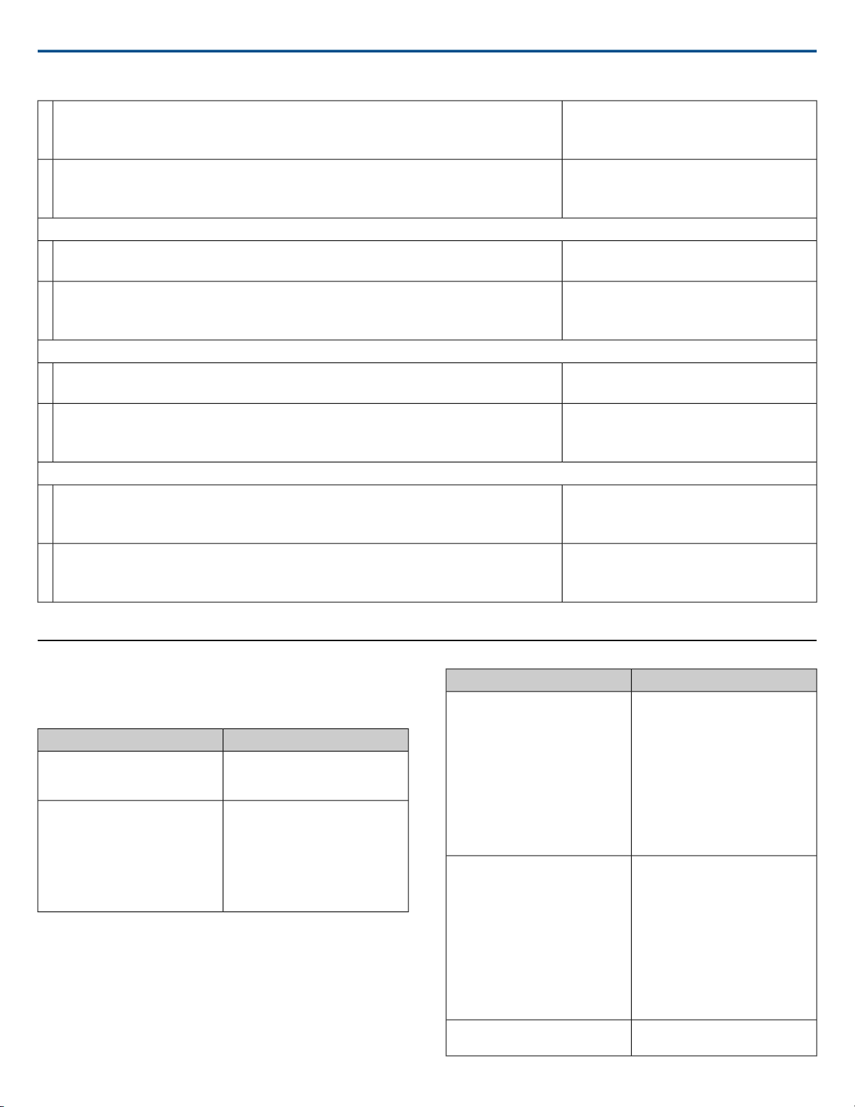
Shure IncorporatedMXA910 Ceiling Array Microphone
Command String:
< SET x CHAN_AUTOMIX_SOLO_EN ENABLE >
< SET x CHAN_AUTOMIX_SOLO_EN DISABLE >
MXA910 Response:
< REP x CHAN_AUTOMIX_SOLO_EN ENABLE >
< REP x CHAN_AUTOMIX_SOLO_EN DISABLE >
Get Encryption Status (firmware > v2.0)
Command String:
< GET ENCRYPTION >
MXA910 Response:
< REP ENCRYPTION ON >
< REP ENCRYPTION OFF >
Get Flash
Command String:
< GET FLASH >
MXA910 Response:
< REP FLASH ON >
< REP FLASH OFF >
Set Flash
Command String:
< SET FLASH ON >
< SET FLASH OFF >
MXA910 Response:
< REP FLASH ON >
< REP FLASH OFF >
where x is channel number: 0 is not valid MXA910:
channels 1-8; where sts determines the requested
state of SOLO mode: ENABLE DISABLE
where x is channel number: 0 is not valid MXA910:
channels 1-8; where sts indicates channel x's SOLO
state: ENABLE DISABLE
Get device level encryption status;
Send one of these commands to the MXA910.
The MXA910 will respond with one of these
commands.
Send one of these commands to the MXA910.
The MXA910 will respond with one of these
commands.
Troubleshooting
Troubleshooting
Troubleshooting
Software lags in Google Chrome
browser
Sound quality is muffled or hollow
SolutionProblem
Problem is browser-related. Turn off
hardware acceleration option in
Chrome.
•Check that lobes have been
aimed to the desired area.
•Use equalizer to adjust frequency
response on a single channel or
on the automix channel. See the
equalizer applications for the ap-
propriate use.
Microphone does not show up in
device discovery
Audio is not present or is
quiet/distorted
No lights
SolutionProblem
•Ensure the devices are powered
•Ensure PC and equipment are on
the same network and set to the
same subnet
•Turn off other network interfaces
not used to connect to the device
(including WiFi)
•Check that DHCP server is func-
tioning (if applicable)
•Reset the device if necessary
•Check cables
•Verify that channels are not muted
•Make sure channels are aimed in
the right direction
•Check that fader levels are not
set too low
•If using automixing, check the
settings to ensure channels are
gating on/off properly
Check if brightness is disabled or if
any Light Bar settings are turned off.
2017/10/1850/57
Page 51
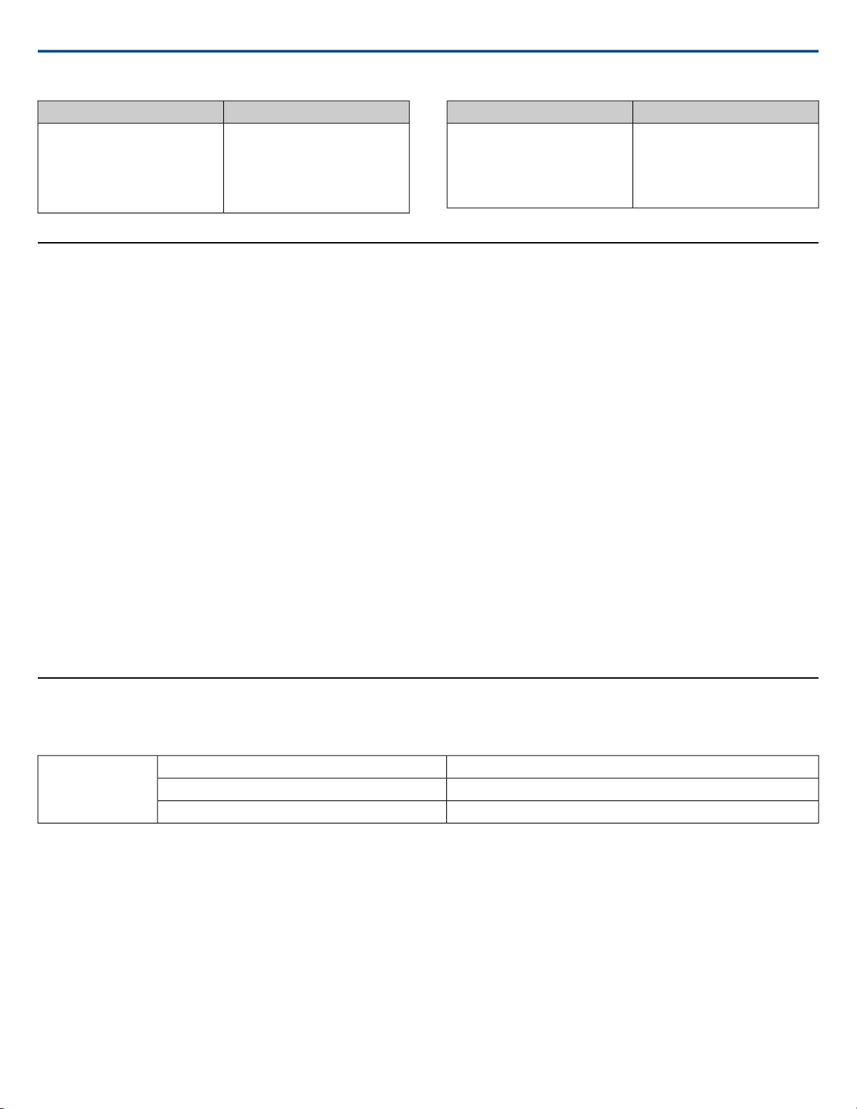
Shure IncorporatedMXA910 Ceiling Array Microphone
SolutionProblem
If talker is in a corner or very close
to a wall, acoustic reflections may
Auto-positioning identifies incorrect
location
interfere with localization accuracy.
Try automatic positioning again, and
if the issue persists, manual
positioning may be necessary.
Important Product Information
The equipment is intended to be used in professional audio applications.
Note:This device is not intended to be connected directly to a public internet
network.
EMC conformance to Environment E2: Commercial and Light Industrial.
Testing is based on the use of supplied and recommended cable types. The
use of other than shielded (screened) cable types may degrade EMC performance.
Changes or modifications not expressly approved by Shure Incorporated
could void your authority to operate this equipment.
Industry Canada ICES-003 Compliance Label:CAN ICES-3 (B)/NMB-3(B)
Authorized under the verification provision of FCC Part 15B.
Please follow your regional recycling scheme for batteries, packaging, and
electronic waste.
Information to the user
This equipment has been tested and found to comply with the limits for a
Class B digital device, pursuant to Part 15 of the FCC Rules. These limits
are designed to provide reasonable protection against harmful interference
in a residential installation. This equipment generates uses and can radiate
radio frequency energy and, if not installed and used in accordance with the
instructions, may cause harmful interference to radio communications.
However, there is no guarantee that interference will not occur in a particular
installation. If this equipment does cause harmful interference to radio or
SolutionProblem
Power over Ethernet. Otherwise,
Microphone does not power on
television reception, which can be determined by turning the equipment off
and on, the user is encouraged to try to correct the interference by one or
more of the following measures:
• Reorient or relocate the receiving antenna.
• Increase the separation between the equipment and the receiver.
• Connect the equipment to an outlet on a circuit different from that to
which the receiver is connected.
• Consult the dealer or an experienced radio/TV technician for help.
The CE Declaration of Conformity can be obtained from:
www.shure.com/europe/compliance
Authorized European representative:
Shure Europe GmbH
Headquarters Europe, Middle East & Africa
Department: EMEA Approval
Jakob-Dieffenbacher-Str. 12
75031 Eppingen, Germany
Phone: +49-7262-92 49 0
Fax: +49-7262-92 49 11 4
Email: [email protected]
This product meets the Essential Requirements of all relevant European directives and is eligible for CE marking.
The CE Declaration of Conformity can be obtained from Shure Incorporated
or any of its European representatives. For contact information please visit
www.shure.com
a PoE injector must be used
•The network switch must supply
•Check network cables and con-
nections
Specifications
All specifications measured from narrow beam width. Values for all widths are within ± 3 dB of these specifications unless otherwise noted.
Beam Width
Adjustable 45 degreesMedium
Connector Type
RJ45
Power Requirements
Power over Ethernet (PoE), Class 0
Power Consumption
9W, maximum
Weight
4.26 kg (9.4 lbs)
35 degreesNarrow
55 degreesWide
51/572017/10/18
Page 52
Product Dimensions
2
control application
HTML5 Browser-based
Plenum Rating
Requires Fyrewrap® fire protective wrap system (Included)
UL 2043 (Suitable for Air Handling Spaces)
Dust Protection
IEC 60529 IP5X Dust Protected
Operating Temperature Range
−6.7°C (20°F) to 40°C (104°F)
Shure IncorporatedMXA910 Ceiling Array Microphone
603.8 x 603.8 mm (23.77 x 23.77 in.)MXA910xx
593.8 x 593.8 mm (23.38 x 23.38 in.)MXA910xx-60CM
619.7 x 619.7 mm (24.4 x 24.4 in.)A910-25MM
Storage Temperature Range
−29°C (-20°F) to 74°C (165°F)
Audio
Frequency Response
180 to 17,000 Hz
Dante Digital Output
Sensitivity
at 1 kHz
0.75 dBFS/Pa
Maximum SPL
Relative to 0 dBFS overload
93.25 dB SPL
Signal-To-Noise Ratio
Ref. 94 dB SPL at 1 kHz
83 dB A-weighted
9 total channels (8 independent transmit channels, 1 IntelliMix® Automatic mixing transmit channel)Channel Count
48 kHzSampling Rate
24Bit Depth
Latency
Not including Dante latency
6 ms
Self Noise
11 dB SPL-A
Dynamic Range
82.25 dB
2
Note: the adapter accessory converts the 600 mm model to fit into a 625 x 625 mm ceiling grid.
2017/10/1852/57
Page 53
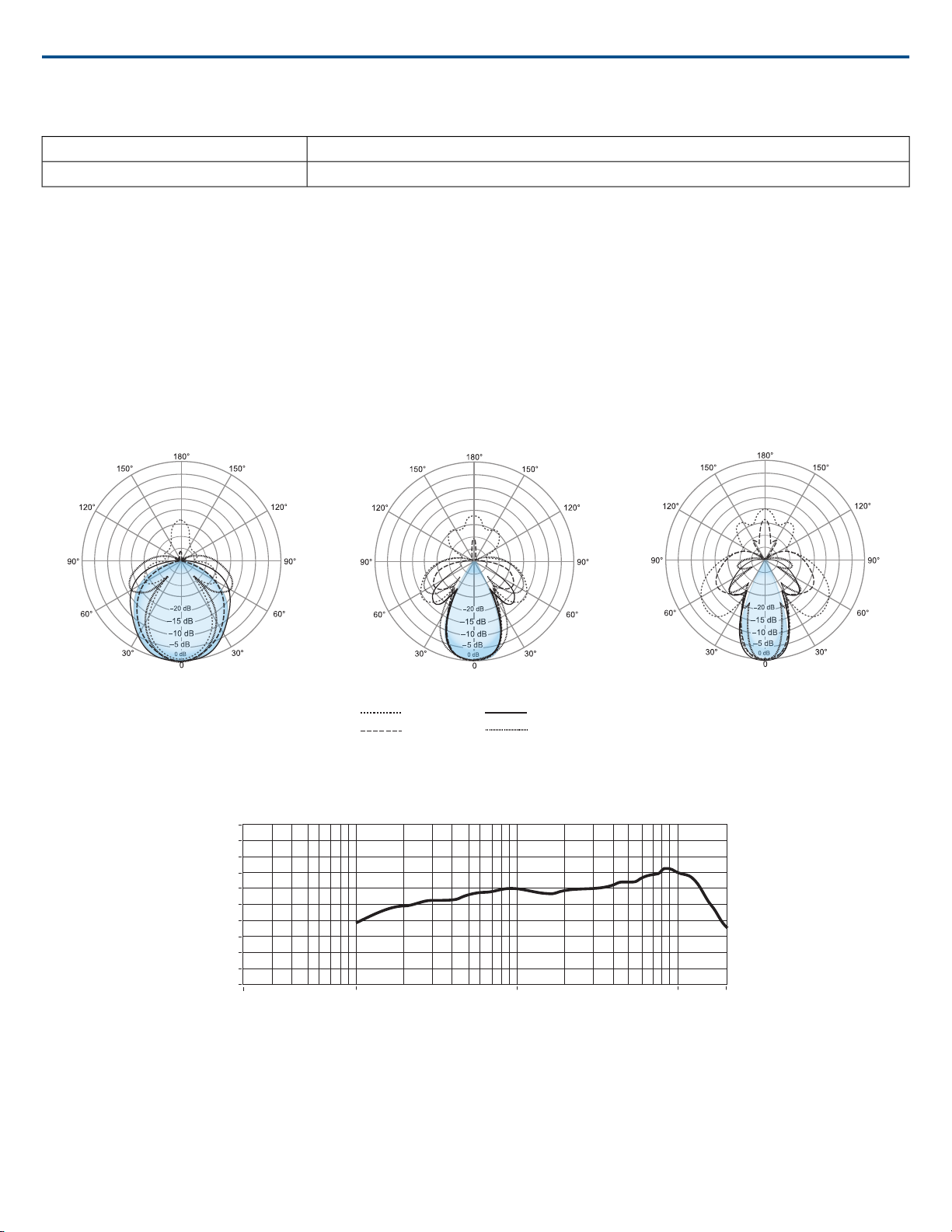
Built-in Digital Signal Processing
4,000 Hz
2,500 Hz
1,500 Hz
1,000 Hz
Wide Medium Narrow
20
15
10
5
0
-30
-25
-20
-15
-10
-5
dB
Hz
20 100 1k 10k 20k
Equalizer (4-band Parametric), Mute, Gain (140 dB range)Per Channel
Intelligibility Scale
Equivalent acoustic performance, compared to a cardioid gooseneck microphone (environment dependent)
Cardioid distance multiplied by 1.6
3
Networking
Cable Requirements
Cat 5e or higher (shielded cable recommended)
Shure IncorporatedMXA910 Ceiling Array Microphone
IntelliMix® Automatic mixing, Echo ReductionSystem
Polar Pattern
Lobe Sensitivity
The edge of the blue coverage area for each channel in the web application represents where the sensitivity reaches -6 dB. Understanding how lobe sensitivity
is displayed helps to:
3
[1] 1 Pa=94 dB SPL
Frequency Response
53/572017/10/18
Page 54

Shure IncorporatedMXA910 Ceiling Array Microphone
• Provide complete coverage in a space, either by adding lobes or changing the lobe width. This ensures the sensitivity is within 6 dB in all areas. It is acceptable
for lobes to slightly overlap.
• Ensure that spacing and isolation are adequate to reduce noise and maximize automatic mixing performance.
Measured at 1 kHz, on-axis
2017/10/1854/57
Page 55
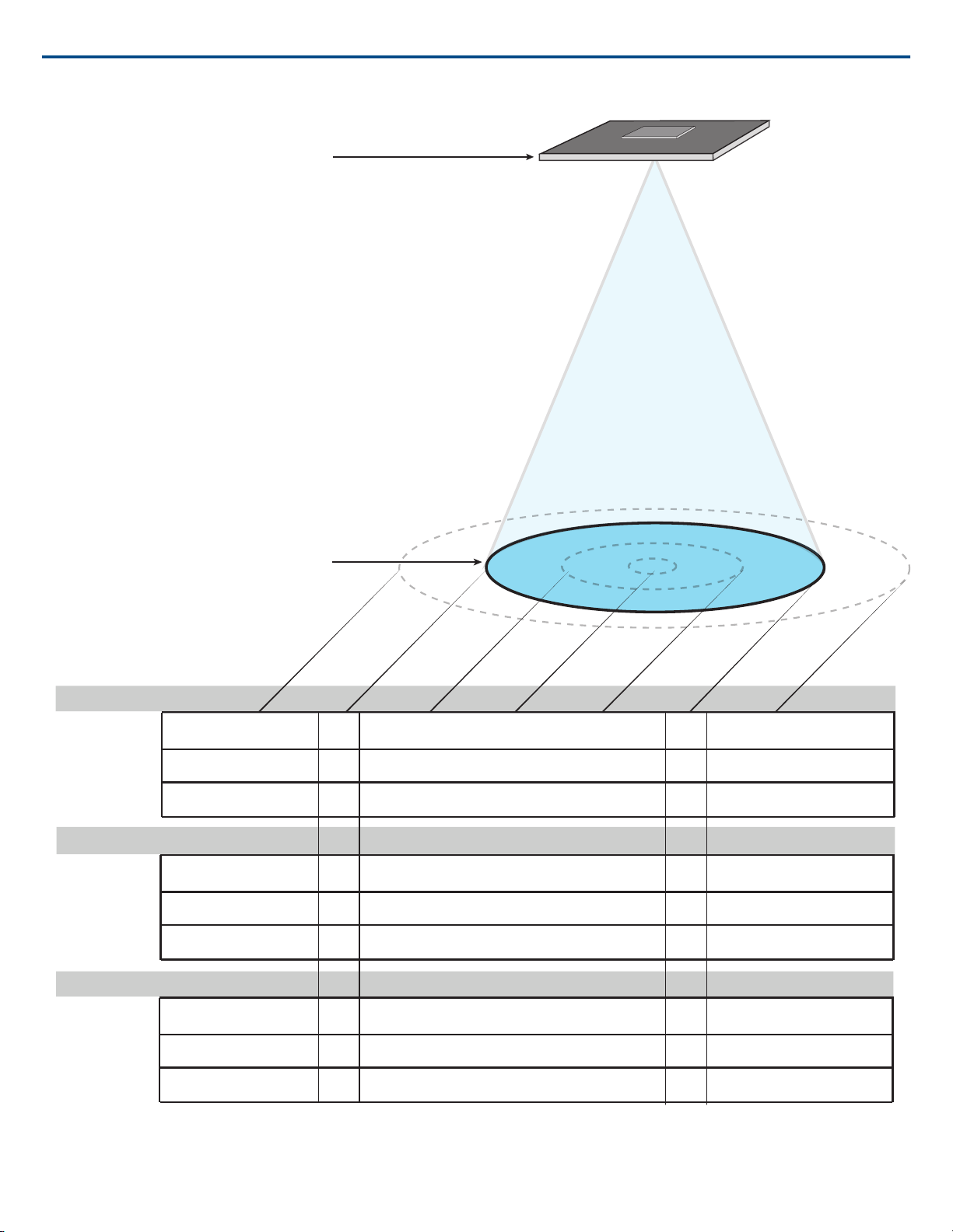
Ceiling height = 9 ft (2.7 m)
Talker height= 4 ft (1.2 m)
Inches
dB
Centimeters
Inches
dB
Centimeters
Inches
dB
Centimeters
0
0
0
-3
-3
-6
-12
-12
-6
17
17 12
12
22
55 44
30
30
44
55
22
0
0
0-3
-3
-6
-12
-12
-6
18
18
15
15
27
69 47
38
38
47
69
27
0
0
0
-3 -3
-6
-12
-12
-6
24
24 17
17
36
92
62 44
44
62
92
36
Narrow
Medium
Wide
Shure IncorporatedMXA910 Ceiling Array Microphone
55/572017/10/18
Page 56
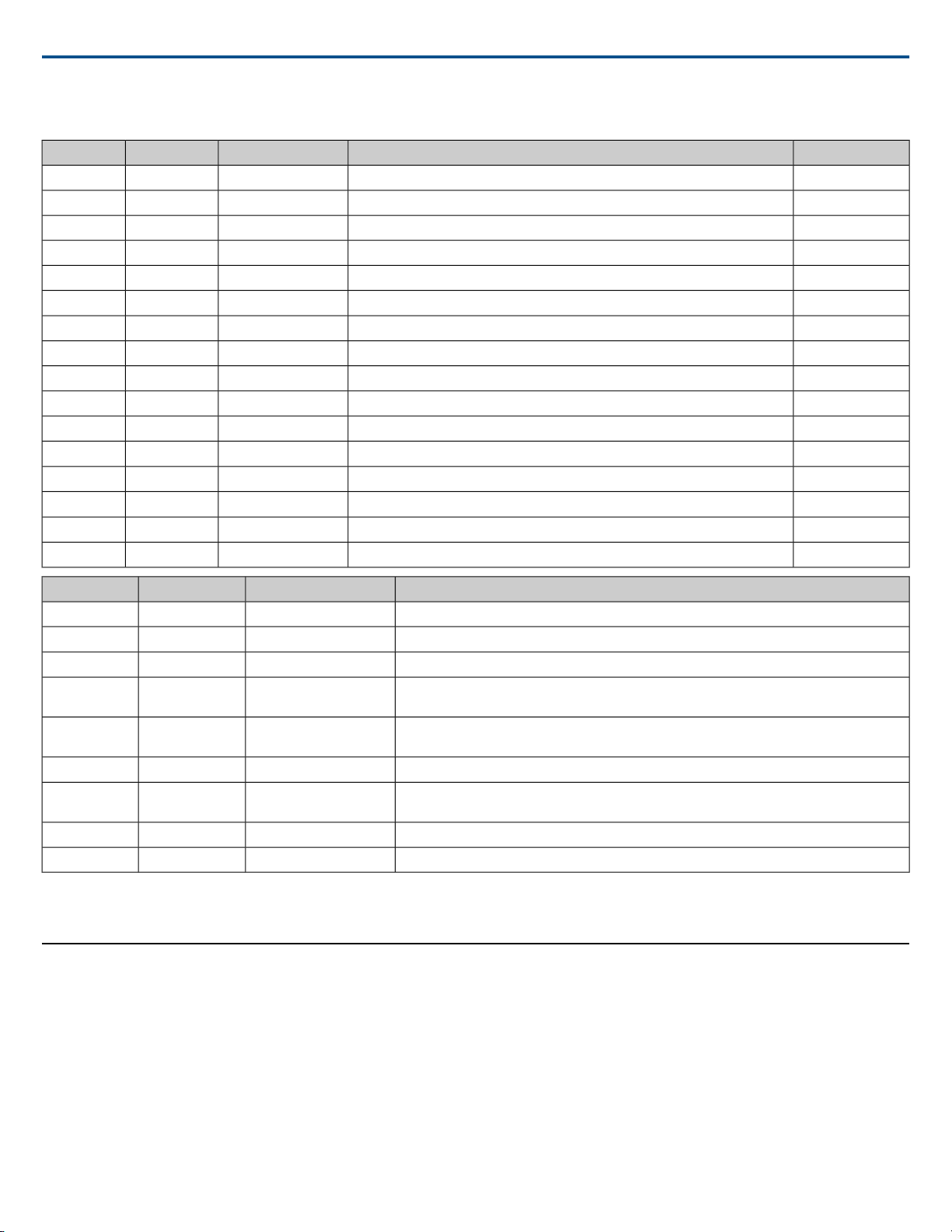
IP Ports and Protocols
427
5353
5568
8180*
8427
tcp/udp
udp
udp
tcp
udp
Shure IncorporatedMXA910 Ceiling Array Microphone
Factory DefaultDescriptionProtocolTCP/UDPPort
ClosedRequired for firmware updates (otherwise closed)FTPtcp21
ClosedNot supportedSSHtcp22
ClosedStandard console interfaceTelnettcp23
OpenDynamic Host Configuration ProtocolDHCPudp68
OpenRequired to launch embedded web serverHTTPtcp80*
OpenRequired for inter-device communicationSLP†
ClosedNot supportedHTTPStcp443
ClosedNot supportedSNMPtcp161
ClosedNot supportedSNMPtcp162
OpenRequired for 3rd party control stringsASCIItcp2202
OpenRequired for device discoverymDNS†
OpenRequired for inter-device communicationSDT†
PasswordDebug console interfaceTelnettcp8023
OpenRequired for web applicationHTML
OpenRequired for inter-device communicationMultcast SLP†
OpenRequired for Shure firmware updateTelnettcp64000
4321,
14336-14600
[4440, 4444,
4455]*
[8700-8706,
8800]*
4 5
Accessories
DescriptionProtocolTCP/UDPPort
Used by DanteSNMPudp162
udp[319-320]*
udp5353
PTP†
Required for packet bridgeCustomudp2203
mDNS†
Dante clocking
Dante audioDanteudp
Dante audio routingDanteudp
Used by Dante
Dante Control and MonitoringDanteudp
Dante ControllerDanteudp8751
Used by DanteDanteudp16000-65536
4
*These ports must be open on the PC or control system to access the device through a firewall.
5
†These protocols require multicast. Ensure multicast has been correctly configured for your network.
2017/10/1856/57
Page 57
Optional Accessories and Replacement Parts
A910-JBJunction Box Accessory
A910-25MM Adapter25 mm expander (fits onto 60 cm model, for 62.5 x 62.5
cm installation)
A910-HCMMXA910 hard ceiling mount
RPM901MXA910W frame and grille assembly
RPM902MXA910AL frame and grille assembly
RPM903MXA910B frame and grille assembly
RPM904MXA910W-60CM frame and grille assembly
RPM905MXA910AL-60CM frame and grille assembly
RPM906MXA910B-60CM frame and grille assembly
Furnished Accessories
95A28365Rubber pad set
95A29877Cable management clip
Shure IncorporatedMXA910 Ceiling Array Microphone
Shure Incorporated 5800 West Touhy Avenue Niles, IL 60714-4608 USA Phone: +1-847-600-2000 Email: [email protected]
57/57
 Loading...