

222
HARTREY AVE., EVANSTON. l L.
MICROPHONES AND
AREA CODE 312/328-9000 . CABLE: SHUREMICRO
ELECTRONIC
60204 U.S.A.
COMPONENTS
DATA
SHEET
MODELS M68RM
AND M68RM-2E
MICROPHONE MIXERS
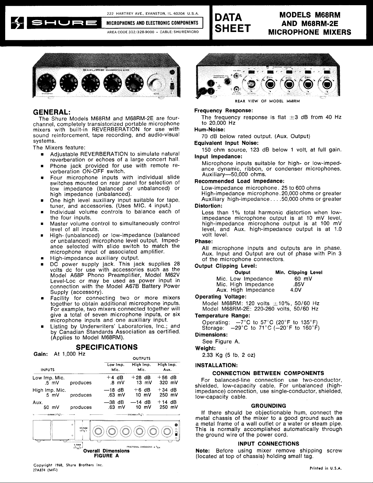
GENERAL:
The Shure Models M68RM and M68RM-2E are fourchannel, completely transistorized portable microphone
mixers with built-in REVERBERATION for use with
sound reinforcement, tape recording, and audio-visual
systems.
The Mixers feature:
Adjustable REVERBERATION to simulate natural
reverberation or echoes of a large concert hall.
Phone jack provided for use with remote reverberation ON-OFF switch.
8
Four microphone inputs with individual slide
switches mounted on rear panel for selection of
low impedance (balanced or unbalanced) or
high impedance (unbalanced).
One high level auxiliary input suitable for tape,
4
tuner, and accessories. (Uses MIC.
input.)
Individual volume controls to balance each of
the four inputs.
Master volume control to simultaneously control
level of all inputs.
High- (unbalanced) or low-impedance (balanced
or unbalanced) microphone level output. Impedance selected with slide switch to match the
microphone input of associated amplifier.
8
High-impedance auxiliary output.
8
DC power supply jack. This jack supplies 28
volts dc for use with accessories such as the
Model A68P Phono Preamplifier, Model M62V
Level-Loc or may be used as power input in
connection with the Model
A67B Battery Power
Supply (accessory).
Facility for connecting two or more mixers
together to obtain additional microphone inputs.
For example, two mixers connected together will
give a total of seven microphone inputs, or six
microphone inputs and one auxiliary input.
Listing by Underwriters' Laboratories, Inc.; and
by Canadian Standards Association as certified.
(Applies to Model
M68RM).
SPECIFICATIONS
Gain:
Low Imp.
High
AUX.
Copyright
27A874
At 1,000 Hz
INPUTS
Mic.
.5 mV produces .8 mV 13 mV
Imp. Mic. -18dB f6dB
5 mV produces .63 mV 10 mV
mV produces .63 mV
50
5..*M
'
(7,,i.iJ
Overall Dimensions
1968,
(MG)
Shure Brothers
Low
Mic. Mic.
+4
-38
FIGURE
Inc.
OUTPUTS
Imp.
High
dB +28 dB
dB -14 dB +14 dB
A
10
FRICTlONlL
--
Imp.
High
Aux.
+56 dB
320
f34 dB
250
mV 250 mV
DIMENSIONS
i
lbgn
Imp.
mV
mV
-
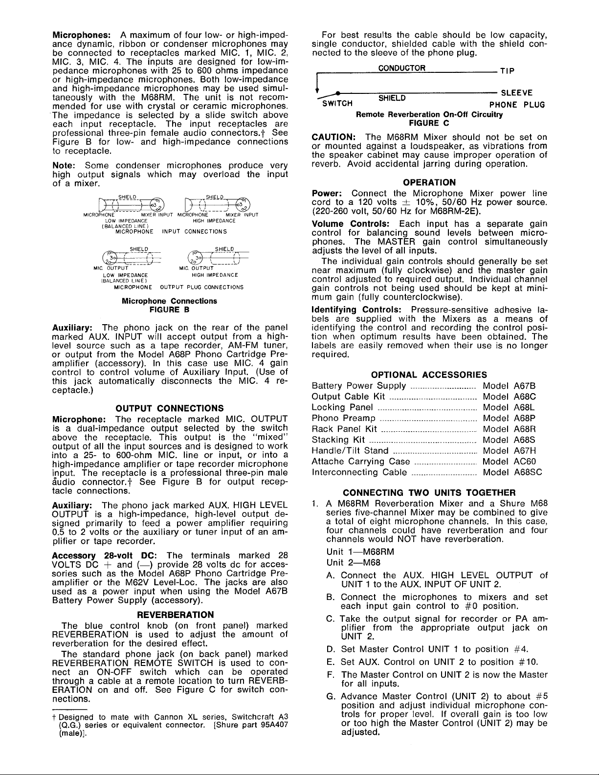
REAR
VIEW
OF
MODEL
M68RM
Frequency Response:
The frequency response is flat 1-3 dB from 40 Hz
to 20,000 Hz
Hum-Noise:
70 dB below rated output. (Aux. Output)
Equivalent lnput Noise:
150 ohm source, 123 dB below 1 volt, at full gain.
lnput Impedance:
Microphone inputs suitable for high- or low-imped-
ance dynamic, ribbon, or condenser microphones.
Auxiliary-50,000 ohms.
Recommended Load Impedance:
Low-impedance microphone. 25 to 600 ohms
High-impedance microphone. 20,000 ohms or greater
Auxiliary high-impedance. . . .50,000 ohms or greater
Distortion:
Less than
l0lo
total harmonic distortion when lowimpedance microphone output is at 10 mV level,
high-impedance microphone output is at 100
mV
level, and Aux. high-impedance output is at 1.0
volt level.
Phase:
All microphone inputs and outputs are in phase.
Aux. lnput and Output are out of phase with Pin 3
of the microphone connectors.
Output Clipping Level:
Output Min. Clipping Level
Mic. Low Impedance 60
mV
Mic. High Impedance .85V
Aux. High lmpedance 4.OV
Operating Voltage:
Model M68RM: 120 volts &lo%, 50/60 Hz
Model
M68RM-2E: 220-260 volts, 50/60 Hz
Temperature Range:
Operating: -7°C to 57°C (20°F to 135°F)
Storage:
-29°C to 71°C (-20°F to 160°F)
Dimensions:
See Figure A.
Weight:
2.33 Kg
.
(5
Ib, 2 oz)
INSTALLATION:
CONNECTION BETWEEN COMPONENTS
For balanced-line connection use two-conductor,
shielded, low-capacity cable. For unbalanced
(high-
impedance) connection, use single-conductor, shielded,
low-capacity cable.
GROUNDING
If there should be objectionable hum, connect the
metal chassis of the mixer to a good ground such as
a metal frame of a wall outlet or a water or steam pipe.
This is normally accomplished automatically through
the ground wire of the power cord.
INPUT CONNECTIONS
Note:
Before using mixer remove shipping screw
(located at top of chassis) holding small tag.
Printed
in
U.S.A.
Microphones: A maximum of four low- or high-impedance dynamic, ribbon or condenser microphones may
be connected to receptacles marked MIC. 1, MIC. 2,
MIC.
3,
MIC.
4.
The inputs are designed for low-impedance microphones with 25 to 600 ohms impedance
or high-impedance microphones. Both low-impedance
and high-impedance microphones may be used simultaneously with the
M68RM. The unit is not recommended for use with crystal or ceramic microphones.
The impedance is selected by a slide switch above
each input receptacle. The input receptacles are
professiona'l three-pin female audio connectors.? See
Figure B for low- and high-impedance connections
to receptacle.
Note: Some condenser microphones produce very
high output signals which may overload the input
of a mixer.
pj?Fl!LQ.w KyEIELD-m
.,.----
MICROPHON~
LOW IMPEDANCE HIGH IMPEDANCE
(BALANCED LINE)
MIC OUTPUT MIC. OUTPUT
LOW IMPEDANCE
(BALANCED LINE
MIXER
INPUT
MICROPHONE MIXER
MICROPHONE INPUT CONNECTIONS
MICROPHONE OUTPUT PLUG CONNECTIONS
)
Microphone Connections
FIGURE
B
HIGH IMPEDANCE
2
SHIELD
INPUT
Auxiliary: The phono jack on the rear of the panel
marked AUX. INPUT will accept output from a highlevel source such as a tape recorder, AM-FM tuner,
or output from the Model
amplifier (accessory). In this case use MIC.
control to control volume of Auxiliary Input.
this jack automatically disconnects the MIC.
A68P Phono Cartridge Pre-
4
gain
(Use of
4
re-
ceptacle.)
OUTPUT CONNECTIONS
Microphone: The receptacle marked MIC. OUTPUT
is a dual-impedance output selected by the switch
above the receptacle. This output is the "mixed"
output of all the input sources and is designed to work
into a 25- to 600-ohm MIC. line or input, or into a
high-impedance amplifier or tape recorder microphone
input. The receptacle is a professional three-pin male
Sudio connector.+ See Figure B for output receptacle connections.
Auxiliary: The phono jack marked AUX.
HlGH LEVEL
OUTPUT is a high-impedance, high-level output designed primarily to feed a power amplifier requiring
0.5 to 2 volts or the auxiliary or tuner input of an am-
plifier or tape recorder.
Accessory 28-volt DC: The terminals marked 28
VOLTS DC
sories such as the Model
amplifier or the
used as a power input when using the Model
+
and
(-)
provide 28 volts dc for acces-
A68P Phono Cartridge Pre-
M62V Level-Loc. The jacks are also
A67B
Battery Power Supply (accessory).
REVERBERATION
The blue control knob (on front panel) marked
REVERBERATION is used to adjust the amount of
reverberation for the desired effect.
The standard phone jack (on back panel) marked
REVERBERATION REMOTE SWITCH is used to connect an ON-OFF switch which can be operated
through a cable at a remote location to turn REVERBERATION on and off. See Figure C for switch con-
nections.
1.
Designed to mate with Cannon
(Q.G.)
series or equivalent connector.
(male)].
XL
series, Switchcraft
[Shure part
A3
95A407
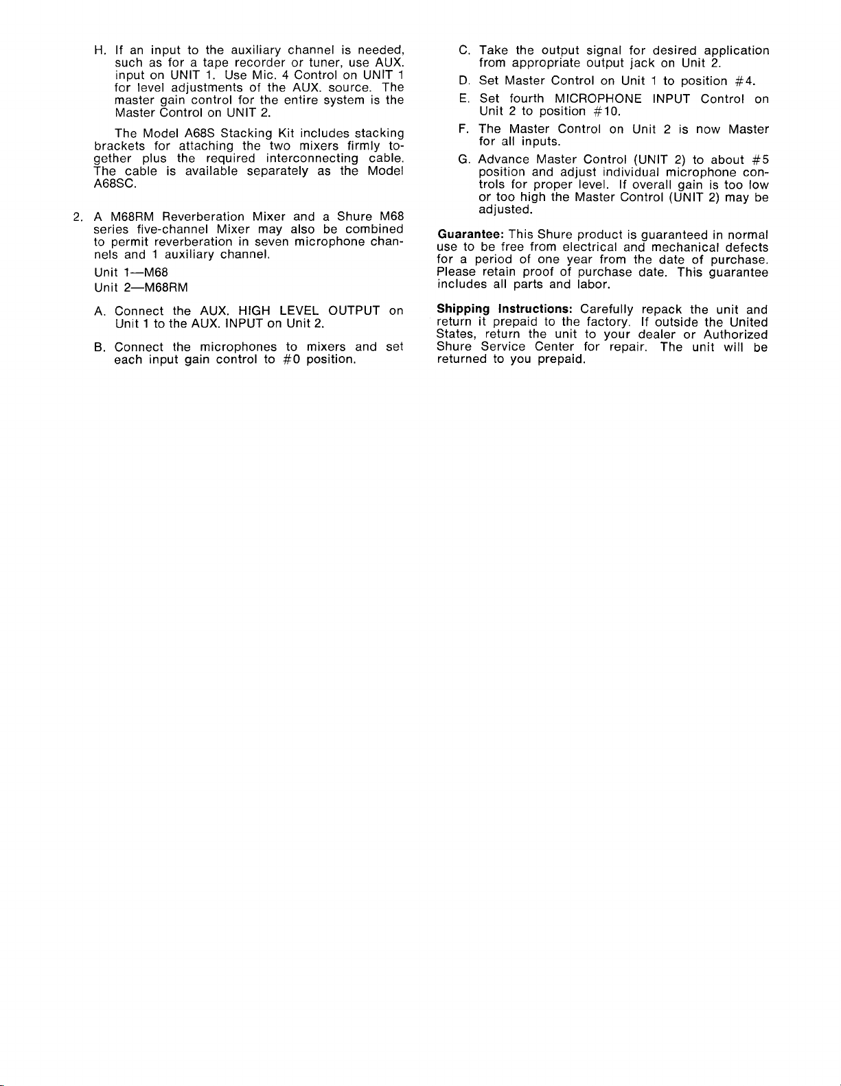
For best results the cable should be low capacity,
single conductor, shielded cable with the shield connected to the sleeve of the phone plug.
SWITCH PHONE PLUG
SHIELD
Remote Reverberation On-Off Circuitry
FIGURE C
SLEEVE
CAUTION: The M68RM Mixer should not be set on
or mounted against a loudspeaker, as vibrations from
the speaker cabinet may cause improper operation of
reverb. Avoid accidental jarring during operation.
OPERATION
Power: Connect the Microphone Mixer power line
-t
cord to a 120 volts
(220-260 volt,
50/60 Hz for M68RM-2E).
lo%, 50/60 Hz power source.
Volume Controls: Each input has a separate gain
control for balancing sound levels between microphones. The MASTER gain control simultaneously
adjusts the level of all inputs.
The individual gain controls should generally be set
near maximum (fully clockwise) and the master gain
control adjusted to required output. Individual channel
gain controls not being used should be kept at minimum gain (fully counterclockwise).
Identifying Controls: Pressure-sensitive adhesive labels are supplied with the Mixers as a means of
identifying the control and recording the control posi-
tion when optimum results have been obtained. The
labels are easily removed when their use is no longer
required.
OPTIONAL ACCESSORIES
Battery Power Supply
Output Cable Kit
Locking Panel
Phono Preamp
Rack Panel Kit
Stacking Kit
HandleITilt Stand
....................................
.........................................
........................................
.......................................
............................................
...................................
Attache Carrying Case
Interconnecting Cable
...........................
.........................
...........................
Model A67B
Model A68C
Model A68L
Model A68P
Model A68R
Model A68S
Model A67H
Model AC60
Model A68SC
CONNECTING TWO UNITS TOGETHER
1.
A M68RM Reverberation Mixer and a Shure M68
series five-channel Mixer may be combined to give
a total of eight microphone channels. In this case,
four channels could have reverberation and four
channels would NOT have reverberation.
Unit
1-M68RM
Unit 2-M68
A. Connect the AUX.
UNlT
1
to the AUX. INPUT OF UNlT
HlGH LEVEL OUTPUT of
2.
B. Connect the microphones to mixers and set
each input gain control to
#O
position.
C. Take the output signal for recorder or PA am-
plifier from the appropriate output jack on
UNlT 2.
D.
Set Master Control UNlT 1 to position
#4.
E. Set AUX. Control on UNlT 2 to position #lo.
F. The Master Control on UNlT 2 is now the Master
for all inputs.
G. Advance Master Control (UNIT 2) to about
#5
position and adjust individual microphone controls for proper level. If overall gain is too low
or too high the Master Control (UNIT 2) may be
adjusted.
H. If an input to the auxiliary channel is needed,
such as for a tape recorder or tuner, use AUX.
input on UNlT
for level adjustments of the AUX. source. The
master gain control for the entire system is the
Master Control on UNlT 2.
The Model
brackets for attaching the two mixers firmly together plus the required interconnecting cable.
The cable is available separately as the Model
A68SC.
2. A M68RM Reverberation Mixer and a Shure M68
series five-channel Mixer may also be combined
to permit reverberation in seven microphone chan-
nels and
Unit 1-M68
Unit
A. Connect the AUX. HIGH LEVEL OUTPUT on
B.
1
auxiliary channel.
2-M68RM
Unit
1
to the AUX. INPUT on Unit 2.
Connect the microphones to mixers and set
each input gain control to
1.
Use Mic. 4 Control on UNlT
A68S Stacking Kit includes stacking
#O
position.
C. Take the output signal for desired application
1
Guarantee:
use to be free from electrical and mechanical defects
for a period of one year from the date of purchase.
Please retain proof of purchase date. This guarantee
includes all parts and labor.
Shipping Instructions:
return it prepaid to the factory. If outside the United
States, return the unit to your dealer or Authorized
Shure Service Center for repair. The unit will be
returned to you prepaid.
from appropriate output jack on Unit 2.
D. Set Master Control on Unit
E.
Set fourth MICROPHONE INPUT Control on
Unit 2 to position
F.
The Master Control on Unit 2 is now Master
for all inputs.
G.
Advance Master Control (UNIT 2) to about
position and adjust individual microphone con-
trols for proper level. If overall gain is too low
or too high the Master Control (UNIT 2) may be
adjusted.
This Shure product is guaranteed in normal
#lo.
Carefully repack the unit and
1
to position #4.
#5

ITEM
DI,D2
QI-Q9
R3,R32
R24-R27
St-S5
S6
TI-T5
T6
PLI
PC1
SHURE PART
NO. OR KIT
RKC21
RKC9
46AOl
l
46AOIO
RKClO
558103
RKC81
51A212
RKC4 5
90A1304
90A1448
QTY IN
RKC KIT
4
4
I
I
4
I
I
I
I
I
I
PARTS LIST
DESCRIPTION
DIODE, SILICON, IN4002 OR EQUIVALENT
NPN TRANSISTOR, SILICON, SELECTED
HIGH
GAIN, LOW NOISE, SIMILAR TO MOTOROLA
MPS 6521
POTENTIOMETER, 50
K
POTENTIOMETER, 20K
SWITCH, SLIDE, DPDT
3
SWITCH, SLIDE, DPDT,
TRANSFORMER-SHIEL
AMF!
D ASSEMBLY
POWER TRANSFORMER
NEON PILOT LIGHT
REVERBERATION
ASSEM. (RESISTOR INTERNAL)
UNIT
PRINTED CIRCUIT BOARD ASSEMBLY
PARTS PLACEMENT
(OVER)
MODELS
M68RM
SAME EXCEPT
snow^
220-260"
50/60Hz
BLUE
GREEN/YELLOW
m
M68RM-2E POWER
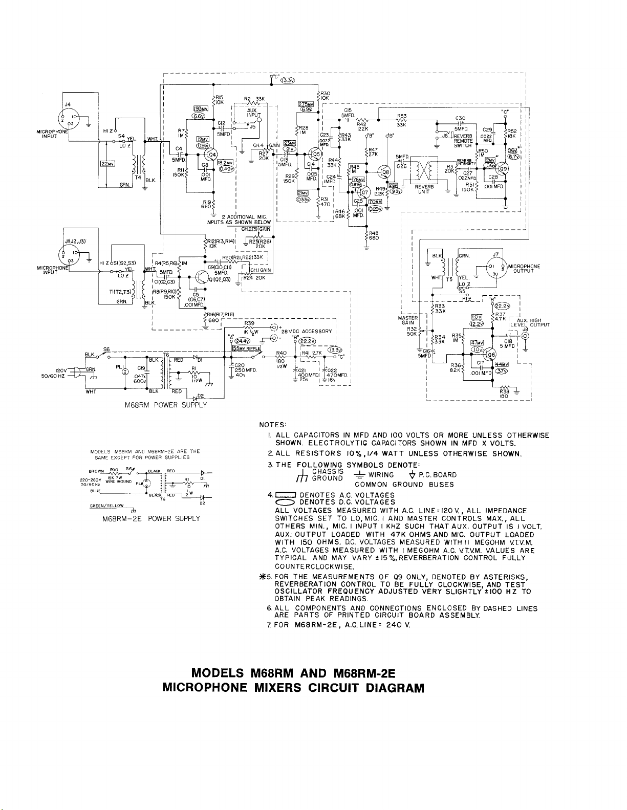
NOTES:
I. ALL CAPACITORS IN MFD AND
AND
M68RM-2E
FOR
POWER
:allF
BLbCK
16
ARE
SUPPLIES
RED
3'
SUPPLY
THE
02
SHOWN. ELECTROLYTIC CAPACITORS SHOWN IN MFD
2.
ALL RESISTORS 10% ,1/4 WATT UNLESS OTHERWISE SHOWN.
3.THE FOLLOWING SYMBOLS DENOTE:
Cf7
4.0
#5.
6.
7.
DENOTES A.C. VOLTAGES
0
DENOTES D.C. VOLTAGES
ALL VOLTAGES MEASURED WlTH A.C.
SWITCHES SET TO LO, MIC. I AND MASTER CONTROLS MAX., ALL
OTHERS MIN., MIC. I INPUT I KHZ SUCH THAT AUX. OUTPUT IS
AUX. OUTPUT LOADED WlTH 47K OHMS AND MIC. OUTPUT LOADED
150 OHMS. D.C. VOLTAGES MEASURED WlTH II MEGOHM VTV.M.
WlTH
A.C. VOLTAGES MEASURED WlTH I MEGOHM A.C. VTVM. VALUES ARE
TYPICAL AND MAY VARY
COUNTERCLOCKWISE.
FOR THE MEASUREMENTS OF
REVERBERATION CONTROL TO BE FULLY CLOCKWISE AND TEST
OSCILLATOR
OBTAIN PEAK READINGS.
ALL COMPONENTS AND CONNECTIONS ENCLOSED BY DASHED LINES
ARE PARTS OF PRINTED CIRCUIT BOARD ASSEMBLY
FOR M68RM-2E, A.C. LINE= 240 V.
&
COMMON GROUND BUSES
FREQUENCY
MODELS M68RM AND M68RM-2E
MICROPHONE MIXERS CIRCUIT DIAGRAM
100
VOLTS OR MORE UNLESS OTHERWISE
WIRING P.C. BOARD
LINE=120V., ALL IMPEDANCE
t
I5
%,
REVERBERATION CONTROL FULLY
Q9
ONLY, DENOTED BY ASTERISKS,
ADJUSTED
VERY
SLIGHTLY'+IOO
X
VOLTS.
HZ
I
VOLT.
TO

 Loading...