

Page 1
222
HARTREY
Q
AREACOOE~https://manualmachine.com/~~E-9000
AVE..
EVANSTON.
. CABLE: SHUREMICRO
IL.
60204
u.s.A.
DATA
SHEET
MODEL M688 AND M688E
STEREO MICROPHONE
MIXERS
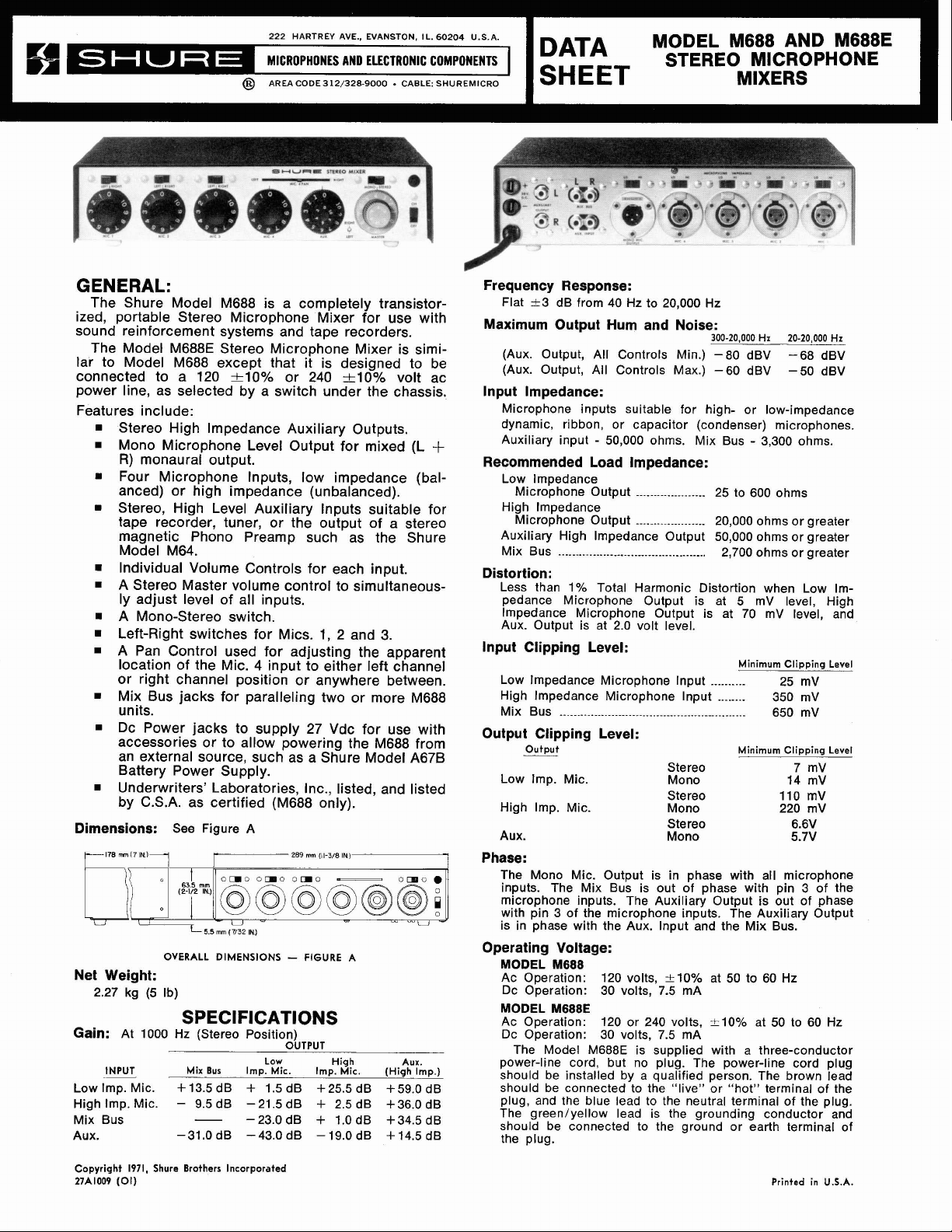
GENERAL:
The Shure Model M688 is a completely transistor-
portable Stereo Microphone Mixer for use with
ized,
sound reinforcement systems and tape recorders.
The Model
M688E Stereo Microphone Mixer is similar to Model M688 except that it is designed to be
connected to a 120
+lo% or 240 &lo% volt ac
power line, as selected by a switch under the chassis.
Features include:
Stereo High lmpedance Auxiliary Outputs.
Mono Microphone Level Output for mixed (L
R)
monaural output.
+
Four Microphone Inputs, low impedance (bal-
anced) or high impedance (unbalanced).
Stereo, High Level Auxiliary Inputs suitable for
tape recorder, tuner, or the output of a stereo
magnetic Phono Preamp such as the Shure
Model M64.
Individual Volume Controls for each input.
A Stereo Master volume control to simu-ltaneous-
ly adjust level of all inputs.
A Mono-Stereo switch.
Left-Right switches for Mics.
1,
2 and
3.
A Pan Control used for adjusting the apparent
location of the Mic. 4 input to either left channel
or right channel position or anywhere between.
Mix Bus jacks for paralleling two or more M688
units.
Dc Power jacks to supply 27 Vdc for use with
accessories or to allow powering the M688 from
an external source, such as a Shure Model
A67B
Battery Power Supply.
Underwriters' Laboratories, Inc., listed, and listed
17/32
IN)
(M688 only).
A
by C.S.A. as certified
Dimensions:
OVERALL
See Figure A
5.5
mm
DIMENSIONS - FIGURE
Net Weight:
2.27 kg (5 Ib)
SPECIFICATIONS
Gain:
Low Imp. Mic. + 13.5 dB + 1.5 dB +25.5 dB +59.0 dB
High Imp. Mic.
Mix Bus
AUX. -31.0 dB
At 1000 Hz (Stereo Position)
INPUT
~-
Mix
Bus
Imp. Mic. Imp. Mic.
-
9.5 dB - 21.5 dB
-
-23.0dB
-43.0 dB
Low
OUTPUT
+
+
-19.0 dB
High
2.5 dB + 36.0 dB
l.OdB +34.5dB
Aux.
(High
Imp.)
+14.5 dB
Frequency Response:
Flat -c3 dB from 40 Hz to 20,000 Hz
Maximum Output Hum and Noise:
(Aux. Output, All Controls Min.) -80 dBV -68 dBV
(Aux. Output, All Controls Max.) -60 dBV -50 dBV
300-20.000
Hz
20-20,000
lnput Impedance:
Microphone inputs suitable for high- or low-impedance
dynamic, ribbon, or capacitor (condenser) microphones.
-
Auxiliary input
50,000 ohms.
Mix Bus
-
3,300 ohms.
Recommended Load Impedance:
Low lmpedance
Microphone Output
High lmpedance
Microphone Output
Auxiliary High lmpedance Output 50,000 ohms or greater
Mix Bus
...........................................
....................
....................
25 to 600 ohms
20,000 ohms or greater
2,700 ohms
or
greater
Distortion:
Less than 1% Total Harmonic Distortion when Low Im-
pedance Microphone Output is at 5
lmpedance Microphone Output is at 70
Aux. Output is at 2.0 volt level.
mV level, High
mV level, and
lnput Clipping Level:
Minimum
Clipping
Low Impedance Microphone Input
High Impedance Microphone Input
Mix Bus
.....................................................
..........
........
25 mV
350 mV
650mV
Output Clipping Level:
Output
Low Imp. Mic.
High Imp. Mic.
Aux.
Stereo
Mono
Stereo
Mono
Stereo 6.6V
Mono 5.7V
Minimum
Clipping
7
mV
14 mV
110 mV
220 mV
Phase:
The Mono Mic. Output is in phase with all microphone
inputs. The Mix Bus is out of phase with pin 3 of the
microphone inputs. The Auxiliary Output is out of phase
with pin
is in phase with the Aux. lnput and the Mix Bus.
3
of the microphone inputs. The Auxiliary Output
Operating Voltage:
MODEL
Ac Operation:
Dc Operation:
MODEL
Ac Operation: 120 or 240 volts, -t-10% at 50 to 60 Hz
Dc Operation:
power-line cord, but no plug. The power-line cord plug
should be installed by a qualified person. The brown lead
should be connected to the "live" or "hot" terminal of the
plug, and the blue lead to the neutral terminal of the plug.
The
should be connected to the ground or earth terminal of
the plug.
M688
M688E
The Model M688E is supplied with a three-conductor
green/yellow lead is the grounding conductor and
120 volts,
30 volts, 7.5
30 volts, 7.5
+-lo% at 50 to 60 Hz
mA
mA
Hz
Level
Level
Copyright
27A1009
(01)
1971,
Shure
Brothers
Incorporated
Printed
in
U.S.A.
Page 2
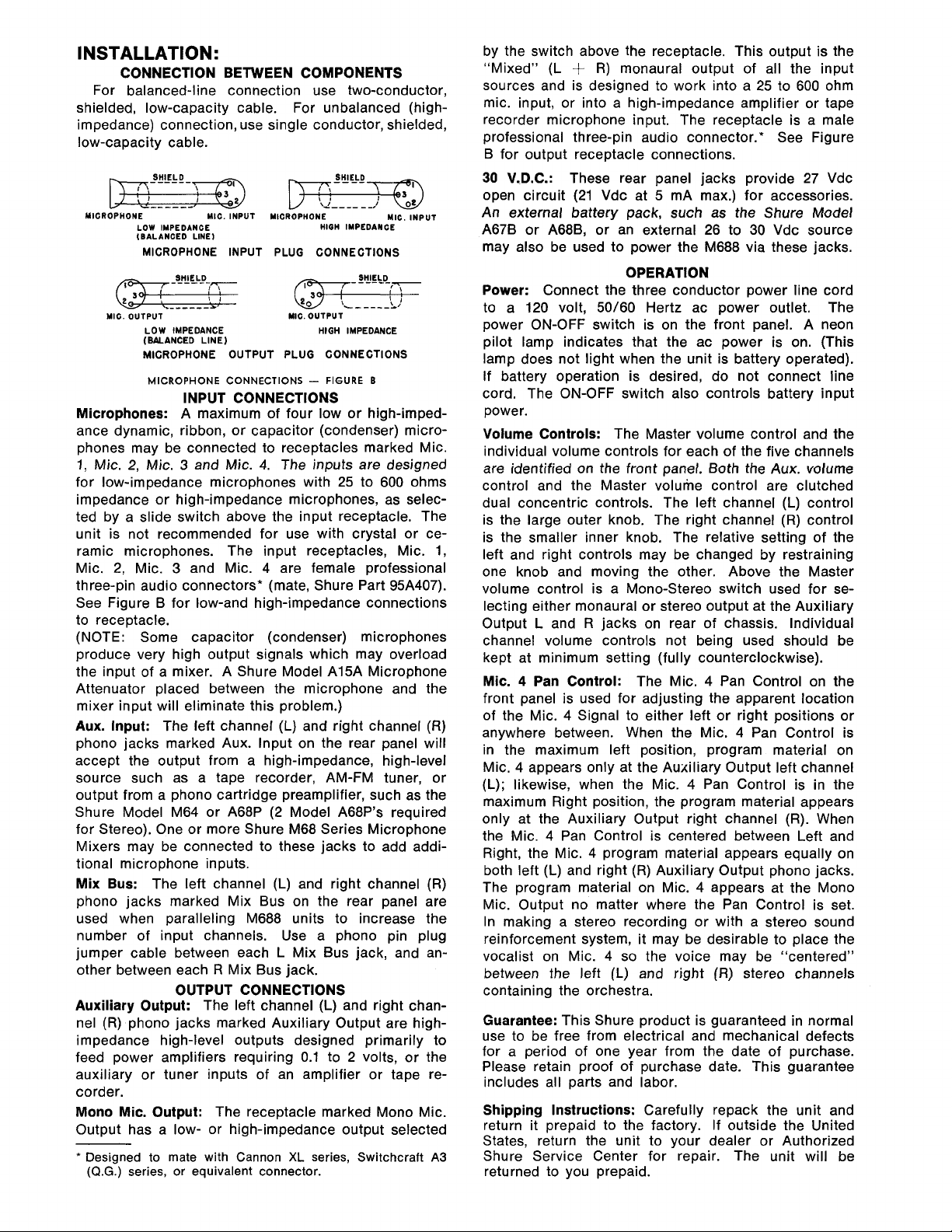
INSTALLATION:
CONNECTION BETWEEN COMPONENTS
For balanced-line connection use two-conductor,
shielded, low-capacity cable. For unbalanced (high-
impedance) connection, use single conductor, shielded,
low-capacity cable.
p.EL!-m
MICROPHONE
-------
LOW
IMPEDANCE
(BALANCED
LINE)
MIC.
INPUT
MICROPHONE INPUT
2
MIC.
OUTPUT
LOW
IMPEDANCE
(BALANCED
MICROPHONE
MICROPHONE CONNECTIONS
LINE)
OUTPUT
INPUT CONNECTIONS
Microphones: A maximum of four low or
ance dynamic, ribbon, or capacitor (condenser) micro-
phones may be connected to receptacles marked Mic.
1,
Mic.
2,
Mic. 3 and
Mic.
for low-impedance microphones with 25 to 600 ohms
impedance or high-impedance microphones, as selected by a slide switch above the input receptacle. The
unit is not recommended for use with crystal or ceramic microphones. The input receptacles, Mic. 1,
3
Mic. 2, Mic.
and Mic. 4 are female professional
three-pin audio connectors* (mate, Shure Part
See Figure B for low-and high-impedance connections
to receptacle.
(NOTE: Some capacitor (condenser) microphones
produce very high output signals which may overload
the input of a mixer. A Shure Model
Attenuator placed between the microphone and the
mixer input will eliminate this problem.)
Aux. Input: The left channel
phono jacks marked Aux. Input on the rear panel will
accept the output from a high-impedance, high-level
source such as a tape recorder, AM-FM tuner, or
output from a phono cartridge preamplifier, such as the
Shure Model M64 or
A68P (2 Model A68P's required
for Stereo). One or more Shure M68 Series Microphone
Mixers may be connected to these jacks to add additional microphone inputs.
Mix Bus: The left channel (L) and right channel (R)
phono jacks marked Mix Bus on the rear panel are
used when paralleling M688 units to increase the
number of input channels. Use a phono pin plug
jumper cable between each L Mix Bus jack, and an-
other between each
R Mix Bus jack.
OUTPUT CONNECTIONS
Auxiliary Output: The left channel (L) and right chan-
nel (R) phono jacks marked Auxiliary Output are highimpedance high-level outputs designed primarily to
feed power amplifiers requiring 0.1 to 2 volts, or the
auxiliary or tuner inputs of an amplifier or tape recorder.
Mono Mic. Output: The receptacle marked Mono Mic.
Output has a low- or high-impedance output selected
*
Designed to mate with Cannon
(Q.G.)
series, or equivalent connector.
p;3EG!m
\1----
MICROPHONE
PLUG
MIC.
OUTPUT
PLUG
-
--/
HIOH
CONNECTIONS
HIGH
CONNECTIONS
FIGURE
MIC.
IMPEDANCE
SHIELD
IMPEDANCE
B
high-imped-
4.
The inputs are designed
95A407).
A15A Microphone
(L)
and right channel (R)
XL
series, Switchcraft
INPUT
A3
by the switch above the receptacle. This output is the
"Mixed"
(L
+
R)
monaural output of all the input
sources and is designed to work into a 25 to 600 ohm
mic. input, or into a high-impedance amplifier or tape
recorder microphone input. The receptacle is a male
professional three-pin audio connector.' See Figure
B for output receptacle connections.
30
V.D.C.: These rear panel jacks provide
open circuit (21 Vdc at 5
mA max.) for accessories.
27
Vdc
An external battery pack, such as the Shure Model
A67B or A68B, or an external 26 to
30
Vdc source
may also be used to power the M688 via these jacks.
OPERATION
Power: Connect the three conductor power line cord
to a 120 volt,
50/60 Hertz ac power outlet. The
power ON-OFF switch is on the front panel. A neon
pilot lamp indicates that the ac power is on. (This
lamp does not light when the unit is battery operated).
If battery operation is desired, do not connect line
cord. The ON-OFF switch also controls battery input
power.
Volume Controls: The Master volume control and the
individual volume controls for each of the five channels
are identified on the front panel. Both the Aux. volume
control and the Master volume control are clutched
dual concentric controls. The left channel (L) control
is the large outer knob. The right channel (R) control
is the smaller inner knob. The relative setting of the
left and right controls may be changed by restraining
one knob and moving the other. Above the Master
volume control is a Mono-Stereo switch used for se-
lecting either monaural or stereo output at the Auxiliary
L
Output
and R jacks on rear of chassis. Individual
channel volume controls not being used should be
kept at minimum setting (fully counterclockwise).
4
Mic.
Pan Control: The Mic. 4 Pan Control on the
front panel is used for adjusting the apparent location
4
of the Mic.
Signal to either left or right positions or
anywhere between. When the Mic. 4 Pan Control is
in the maximum left position, program material on
Mic. 4 appears only at the Auxiliary Output left channel
(L); likewise, when the Mic. 4 Pan Control is in the
maximum Right position, the program material appears
only at the Auxiliary Output right channel (R). When
the Mic. 4 Pan Control is centered between Left and
Right, the Mic. 4 program material appears equally on
both left (L) and right (R) Auxiliary Output phono jacks.
The program material on Mic. 4 appears at the Mono
Mic. Output no matter where the Pan Control is set.
In making a stereo recording or with a stereo sound
reinforcement system, it may be desirable to place the
4
vocalist on Mic.
so the voice may be "centered"
between the left (L) and right (R) stereo channels
containing the orchestra.
Guarantee: This Shure product is guaranteed in normal
use to be free from electrical and mechanical defects
for a period of one year from the date of purchase.
Please retain proof of purchase date. This guarantee
includes all parts and labor.
Shipping Instructions: Carefully repack the unit and
return it prepaid to the factory. If outside the United
States, return the unit to your dealer or Authorized
Shure Service Center for repair. The unit will be
returned to you prepaid.
Page 3

OPTIONAL ACCESSORIES
M64 STEREO PREAMPLIFIER
The M64 will furnish the voltage gain and equalization necessary to operate magnetic phono cartridges
(such as Shure Stereo
Dynetic Cartridges), and tape
playback heads into stereo audio amplifiers and
mixers that have aux. level inputs with no equalization such as the Model
M688.
A68M MICROPHONE PREAMPLIFIER
The
A68M will provide a balanced line input or an
additional microphone channel to the Model
The input may be matched to a low impedance
balanced microphone, a high impedance unbalanced
microphone, or a balanced line. The Aux. Output
is terminated in a shielded cable with phono pin
plug for connection to the
M688. The A68M mounts
to the left side of the M688 and is powered by the
M688 power jacks. The
A68M's may be mounted
side-by-side to provide a stereo pair.
A68S STACKING KIT
This accessory consists of brackets for vertical
stacking of an M688 Mixer and any combination of
Shure Mixers or Controllers. An interconnecting
cable is included for connecting one channel. An
additional
A68SC (see next column) interconnecting
cable is required for connecting the second stereo
channel.
A68C OUTPUT CABLE KIT
The
A68C Output Cable Kit provides a convenient
and flexible method of connecting the microphone
level output of the M688 Mixer to the great variety
of amplifier and input receptacle configurations.
PA
Enables you to connect to virtually any
system.
Kit Includes:
One 4.6 m (15 ft) two-conductor shielded ca-
ble with male and female professional threepin connectors.*
One 305 mm (12 in.) two-conductor shielded
adapter cable with female professional threepin audio connector* on one end and
bell twist lock plug on other end.
One 305 mm
(12
in.) single conductor shielded
adapter cable with female professional threepin audio connector* on one end and Amphenol type
MC1 on the other end.
M688.
Hub-
A68SC INTERCONNECTING CABLE
This cable is a 305 mm
(12
in.) long single conductor
shielded cable with a phono plug on each end for
interconnecting an M688 Mixer in combination with
other Shure mixers or controllers.
A68R RACK PANEL KIT
The kit consists of a 483 mm x 90 mm (19 in. x
in.) precut rack panel and necessary hardware for
rack mounting of the M688 with its cover in place.
A68L LOCKING PANEL
This panel fits within the front hood of the M688
cover and locks in place to prevent tampering with
the front panel controls.
A67H HANDLEITILT STAND
A67H provides a convenient means of tilting
The
the M688 to permit better panel visibility and greater
ease of operation in some conditions. In the locked
(tilt) position, the front panel will be elevated about
20°. In the free position, the A67H serves as a
rugged carrying handle.
This case is compartmentalized and foam lined for
an M688 and accessories.
A67B BATTERY POWER SUPPLY
A67B eliminates need to connect the M688
The
Mixer to a wall outlet. The battery complement is
three
Eveready type
batteries. At room temperature, the
222, 216,
or equivalent 9 volt
A67B will oper-
ate the M688 continuously for approximately 40
hours.
31/2
e
One Phone Plug adapter for use with Amphenol type MC1 Connector.
*
Designed to mate with Cannon
(Q.G.)
series, or equivalent connector.
XL
series, Switchcraft
A3
Page 4

K
MIXER
VOLTS OR MORE UNLESS
100
VOLTS.
X
ALL CAPPCITORS IN MFD AND
MFD
OTHERWISE SHOWN. ELECTROLYTIC CAPACITORS SHOWN IN
I.
BOARD
+PC.
+WIRING
COMMON GROUND BUSSES
10%. 1/4 WATT, UNLESS OTHERWISE SHOWN.
GROUND
M~1,000.000.
1000,
,+CHASSIS
K.
THE FOLLOWING SYMBOLS DENOTE:
2. ALL RESISTORS
3.
12OU, ALL
*
IKHZ SUCH THAT LEFT
MIC4 AND MASTER CONTROLS
DENOTES D.C. VOLTAGES.
INP~T
0
OUTPUT LOADED WlTH 47K OHMS
MIC4
IVOLT.'AUX.
IS
~UTPUT
IMPEDANCE SWITCHES SET TO LO
ALL VOLTAGES MEASURED WlTH A.C. LINE
AUX.
MAX. ALL OTHERS MIN.
4.ODENOTES A.C. VOLTAGES.
MEG-
I
15%.
f
D.C.VOLTAGES MEASURED
MEGOHM V.T.V.M. A.C. VOLTAGES MEASURED WlTH
I
I
OHM LC. VT.V.M. VALUES ARE TYPICAL AND M4Y VARY
WlTH
AND MIC OUTPUT LOADED WITH 150 OHMS. ALL INPUT SWITCHES
AND PAN POT SET TO LEFT POSITION.
ALL COMPONENTS AND CONNECTIONS ENCLOSED BY DASHED
LINES ARE PARTS OF PRINTED CIRCUIT BOARD ASSEMBLY.
5.
6. ARROWS ON POTENTIOMETERS DENOTE CLOCKWISE
~106.
OF
C103 WAS.047.600V AND WIRED ACROSS PRIMARY
ROTATION.
*
7
CIRCUIT DIAGRAM
MODEL M688 STEREO MICROPHONE
PREAMP SHOWN,
I
MIC
r---------------
M688 POWER SUPPLY
---
INPUT
ACLINE
W/60 HZ.
TI06
dl
GREEN /YFI LOW
,
M6BBE POWER SUPPLY
---
Page 5

PRINTED CIRCUIT BOARD ASSEMBLY
PARTS PLACEMENT
ITEM
DIOI, Dl02
PLlOl
QI-~9%
RIOI- R103, R107
R108
R113, R114
SIOJ-S104,5108
S105-S107. SllO
S109
Slll
TIOI-TI05
TI06
FlOl
SHURE
86A404
80A79
866349
46AOll
46A029
46A030
55854
55883
558103
55A66
90E2150
518252
80A155
PART
NO.
SHURE
RKC21
RKC45
RKC9
-
RKCIO
-
-
-
KIT
NO.
,PARTS LIST
Q$Y
IN
KIT
4
I
4
4
-
-
-
-
(M688E ONLY)
(M688E - HIDDEN)
(M688E ONLY)
DIODE. SILICON. IN4002 OR EQUIVALENT
PILOT LIGHT. NEON,
NPN TRANSISTOR, SILICON, SELECTED
LOW NOISE SIMILAR TO MOTOROLA
MPS 6521
POTENTIOMETER, ROTARY
POTENTIOMETER. SLIDE, IOK, SPECIAL LINEAR TAPER.
POTENTIOMETER, DUAL ROTARY.
SWITCH, SLIDE, SLOTTED BUTTON, DPDT
SWITCH, SLIDE. DPDT.
SWITCH, SLIDE. DPDT, 3 AMP
SWITCH.SLIDE, DPDT
TRANSFORMER AND SHIELD ASSEMBLY
.
TRANSFORMER, POWER
FUSE, 1/16
DESCRIPTION
A,250
WITH RESISTOR
HIGH GAIN,
50K, SPEClAL LINEAR TAPER.
50K, AUDIO TAPER.
V
*TO INSURE LOW NOISE FIGURE,
PURCHASE
REPLACEMENTS FOR QI-09 FROM SHURE BROTHERS INEORPORAED
 Loading...