

Shure M63 AUDIO MASTER Techical Data
PRODUCTS
DATA
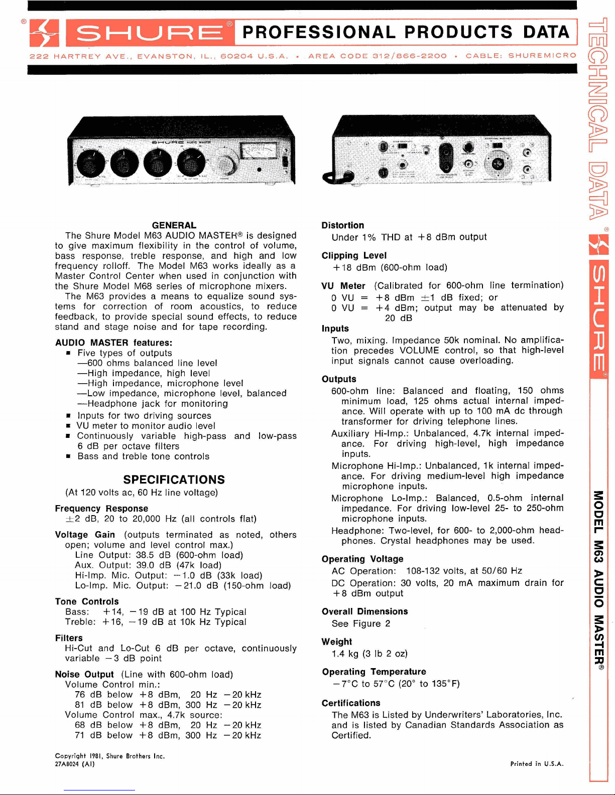
GENERAL
The Shure Model M63 AUDIO
MASTER@ is designed
to give maximum flexibility in the control of volume,
bass response, treble response, and high and low
frequency
rolloff. The Model M63 works ideally as a
Master Control Center when used in conjunction with
the Shure Model M68 series of microphone mixers.
The M63 provides a means to equalize sound systems for correction of room acoustics, to reduce
feedback, to provide special sound effects, to reduce
stand and stage noise and for tape recording.
AUDIO MASTER features:
m
Five types of outputs
-600 ohms balanced line level
-High impedance, high level
-High impedance, microphone level
-Low impedance, microphone level, balanced
-Headphone jack for monitoring
=
Inputs for two driving sources
=
VU meter to monitor audio level
=
Continuously variable high-pass and low-pass
6 dB per octave filters
Bass and treble tone controls
SPECIFICATIONS
(At 120 volts ac, 60 Hz line voltage)
Frequency Response
-t2 dB, 20 to 20,000 Hz (all controls flat)
Voltage Gain (outputs terminated as noted, others
open; volume and level control max.)
Line Output: 38.5 dB (600-ohm load)
Aux. Output: 39.0 dB (47k load)
Hi-Imp. Mic. Output: -1.0 dB (33k load)
Lo-Imp. Mic. Output: -21.0 dB (150-ohm load)
Tone Controls
Bass:
+
14, - 19 dB at 100 Hz Typical
Treble: + 16, - 19 dB at 10k Hz Typical
Filters
Hi-Cut and Lo-Cut 6 dB per octave, continuously
variable -3 dB point
Noise Output (Line with 600-ohm load)
Volume Control min.:
76 dB below
+8 dBm, 20 Hz -20 kHz
81 dB below
+8 dBm, 300 Hz -20 kHz
Volume Control max.,
4.7k source:
68 dB below
+8 dBm, 20 Hz -20 kHz
71 dB below
+8 dBm, 300 Hz - 20 kHz
Distortion
Under 1% THD at
+8 dBm output
Clipping Level
+18
dBm (600-ohm load)
VU
Meter (Calibrated for 600-ohm line termination)
0 VU = +8 dBm
tl
dB fixed; or
0 VU = +4 dBm; output may be attenuated by
20 dB
Inputs
Two, mixing. Impedance 50k nominal. No amplification precedes VOLUME control, so that high-level
input signals cannot cause overloading.
Outputs
600-ohm line: Balanced and floating, 150 ohms
minimum load, 125 ohms actual internal impedance. Will operate with up to 100
mA dc through
transformer for driving telephone lines.
Auxiliary Hi-Imp.: Unbalanced,
4.7k internal impedance. For driving high-level, high impedance
inputs.
Microphone Hi-Imp.: Unbalanced,
I
k internal impedance. For driving medium-level high impedance
microphone inputs.
Microphone Lo-Imp.: Balanced, 0.5-ohm internal
impedance. For driving low-level 25- to 250-ohm
microphone inputs.
Headphone: Two-level, for 600- to 2,000-ohm head-
phones. Crystal headphones may be used.
Operating Voltage
AC Operation:
108-132 volts, at
50160 Hz
DC
Operation: 30 volts, 20 mA maximum drain for
+8 dBm output
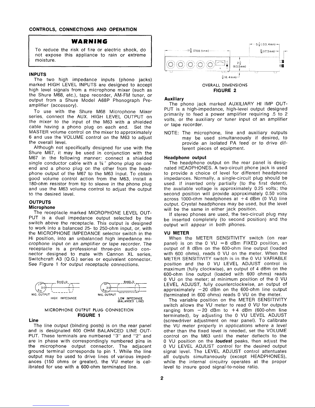
Overall Dimensions
See Figure 2
Weight
1.4 kg (3
Ib 2 oz)
Operating Temperature
-7°C to 57°C (20" to 135°F)
Certifications
The M63 is Listed by Underwriters' Laboratories, Inc.
and is listed by Canadian Standards Association as
Certified.
Copyright 1981, Shure Brothers Inc.
27A8024 (Al)
Printed in
U.S.A.
CONTROLS, CONNECTIONS AND OPERATION
WARNING
To reduce the risk of fire or electric shock, do
not expose this appliance to rain or extreme
moisture.
1
INPUTS
The two high impedance inputs (phono jacks)
marked HlGH LEVEL INPUTS are designed to accept
high level signals from a microphone mixer (such as
the Shure M68, etc.), tape recorder, AM-FM tuner, or
output from a Shure Model
A68P Phonograph Pre-
amplifier (accessory).
To use with the Shure M68 Microphone Mixer
series, connect the AUX. HlGH LEVEL OUTPUT on
the mixer to the input of the M63 with a shielded
cable having a phono plug on each end. Set the
MASTER volume control on the mixer to approximately
6 and use the VOLUME control on the M63 to adjust
the overall level.
Although not specifically designed for use with the
Shure M67, it may be used in conjunction with the
M67 in the following manner: connect a shielded
single conductor cable with a
%"
phone plug on one
end and
a phono plug on the other from the head-
phone output of the M67 to the M63 input. To obtain
good volume control action from the M63, install a
180-ohm resistor from tip to sleeve in the phone plug
and use the M63 volume control to adjust the output
to the desired level.
OUTPUTS
Microphone
The receptacle marked MICROPHONE LEVEL OUT-
PUT is a dual impedance output selected by the
switch above the receptacle. This output is designed
to work into a balanced 25- to 250-ohm input, or, with
the MICROPHONE IMPEDANCE selector switch in the
Hi position, into an unbalanced high impedance microphone input on an amplifier or tape recorder. The
receptacle is a professional three-pin audio con-
nector designed to mate with Cannon XL series,
Switchcraft A3 (Q.G.) series or equivalent connector.
See Figure
1
for output receptacle connections.
WELDD_
10
.
-
-
SHIELD
-
- -
- -
!T"-
e3
;
\------A/
\
I
,-------I
MIC. OUTPUT MIC. OUTPUT
HlGH IMPEDANCE
LOW IMPEDANCE
(BALANCED LINE)
MICROPHONE OUTPUT PLUG CONNECTION
FIGURE
1
Line
The line output (binding posts) is on the rear panel
and is designated 600 OHM BALANCED
LINE OUT-
PUT. These terminals are numbered
"3" and
"2"
and
are in
phase with correspondingly numbered pins in
the microphone output connector. The adjacent
ground terminal corresponds to pin 1. While the line
output may be used to drive lines of various imped-
ances (150 ohms or greater), the VU meter is calibrated for use with a 600-ohm terminated line.
OVERALL DIMENSIONS
FIGURE
2
Auxiliary
The phono jack marked AUXILIARY HI IMP OUTPUT is a high-impedance, high-level output designed
primarily to feed a power amplifier requiring
.5
to 2
volts, or the auxiliary or tuner input of an amplifier
or tape recorder.
NOTE: The microphone, line and auxiliary outputs
may be used simultaneously if desired, to
provide an isolated PA feed or to drive different pieces of equipment.
Headphone output
The headphone output on the rear panel is desig-
nated HEADPHONES. A two-circuit phone jack is used
to provide a choice of level for different headphone
impedances. Normally, a single-circuit plug should be
used. If inserted only partially (to the first detent),
the available voltage is approximately 0.25 volts; the
second position will provide approximately 0.50 volts
across 1000-ohm headphones at
+4
dBm (0 VU) line
output. Crystal headphones may be used, but the level
will be the same in either jack position.
If stereo phones are used, the two-circuit plug may
be inserted completely (to second position) and the
output will appear in both phones.
VU METER
When the METER SENSITIVITY switch (on rear
panel) is on the
0 VU =8 dBm FIXED position, an
output of 8
dBm on the 600-ohm line output (loaded
with 600 ohms), reads
0 VU on the meter. When the
METER SENSITIVITY switch is in the
0 VU VARIABLE
position and the
0 VU LEVEL ADJUST control is
maximum (fully clockwise), an output of
4
dBm on the
600-ohm line output (loaded with 600 ohms) reads
0
VU on the meter; at minimum position of the 0 VU
LEVEL ADJUST, fully counterclockwise, an output of
approximately -20
dBm on the 600-ohm line output
(terminated in 600 ohms) reads
0 VU on the meter.
The variable position on the METER SENSITIVITY
switch allows the VU meter to read
0
VU for outputs
ranging from -20
dBm to
-I-
4
dBm (600-ohm line
terminated), by adjusting the
0 VU LEVEL ADJUST
(screwdriver adjustment on rear panel). To calibrate
the VU meter properly in applications where a level
other than the fixed level is needed, set the VOLUME
control on the M63 until the meter deflects to the
0
VU position on the
loudest
peaks, then adjust the
0 VU LEVEL ADJUST control for the desired output
signal level. The LEVEL ADJUST control attentuates
all outputs simultaneously (except HEADPHONES),
while the internal circuitry operates at the proper
level to insure good signal-to-noise ratio.
 Loading...