

Page 1
222 HARTREY AVE., EVANSTON, IL. 60204 U.S.A. • AREA CODE 312/328-9000 • CABLE: SHUREMlCRO
General: The Shure Model M63 Audio Master is a
unit designed to give maximum flexibility in the control of volume, bass response, treble response, and high
and low frequency roll-off. The Model M63 works
ideally as a Master Control Center when used in
conjunction with the Shure Model M68 Series of
Microphone Mixers.
The M63 provides a means to equalize sound
systems for correction of room acoustics, to reduce
feedback, to provide special sound effects, to reduce
stand and stage noise and for tape recording.
The Model M63-2E Audio Master is similar to Model
M63 except that it is designed to be connected to a
220-260 volt AC power line.
All information on the data sheet for the Model
M63 applies, except for those references to AC
operating voltage and power line cord.
The Audio Master features:
l Five types of outputs
–600 ohms balanced line level
–High impedance, high level
–High impedance microphone level
–Low impedance microphone level, balanced
–Headphone jack for monitoring
l Inputs for two driving sources
l A VU meter to monitor audio level
l Continuously variable high pass and low pass
6 db per octave filters
l
Bass and treble tone controls
Controls, Connections and Operation
INPUTS
The two high impedance inputs (phono jacks) marked
HIGH LEVEL INPUTS are designed to accept high
level signals from a microphone mixer such as the
Shure M68, M68RM, etc.), tape recorder, AM-FM
tuner, or output from Shure Model A68P Phonograph
Preamplifier (accessory).
To use with the Shure M68 Microphone Mixer
series, connect the AUX. HIGH LEVEL OUTPUT on
the mixer to the input of the M63 with a shielded
cable having a male phono plug on each end (such as
the Shure A68SC). Set the MASTER volume control
on the mixer to approximately 6 and use the VOLUME
control on the M63 to adjust the overall level.
Although not specifically designed for use with the
Shure M67, it may be used in conjunction with the
M67 in the following manner: connect a shielded
single conductor cable with a ¼” phone plug on one
end and a phono plug on the other from the head-
phone output of the M67 to the M63 input. To obtain
good volume control action from M63, install a 180-ohm
resistor from tip to sleeve in the phone plug and use
the M63 volume control to adjust output to desired level.
Copyright 1973, Shure Brothers Inc.
27A909 (MH)
OUTPUTS
Microphone
The receptacle marked MICROPHONE LEVEL
OUTPUT is a dual impedance output selected by
the switch above the receptacle. This output is
designed to work into a balanced 25 to 250 ohm input, or, with the MICROPHONE IMPEDANCE
selector switch in the Hi position, into an unbalanced high impedance microphone input on
an amplifier or tape recorder. The receptacle is a
professional three-pin male audio connector designed to mate with Cannon XL series, Switchcraft
A3 (Q.G.) series or equivalent connector (Shure
Part 95A548). See Figure A for output receptacle
connections.
Line
The line output (binding posts) is on the rear panel
and is designated 600 OHM BALANCED LINE
OUTPUT. These terminals are numbered “3” and
“2” and are in phase with correspondingly numbered pins in the microphone output connector. The
adjacent ground terminal corresponds to pin I. While
the line output may be used to drive lines of various
impedances (150 ohms or greater), the VU meter
is calibrated for use with a 600 ohm terminated
line.
Auxiliary
The phono jack marked AUXILIARY HI IMP OUTPUT is a high-impedance, high-level output designed primarily to feed a power amplifier requiring .5 to 2 volts, or the auxiliary or tuner input
of an amplifier or tape recorder.
NOTE: The microphone, line and auxiliary outputs
may be used simultaneously if desired, to
provide an isolated PA feed or to drive
different pieces of equipment.
Headphone output
The headphone output on the rear panel is designated HEADPHONES. A two-circuit phone jack is
used to provide a choice of level for different
headphone impedances. Normally, a single-circuit
plug should be used. If inserted only partially (to
the first detent), the available voltage is approximately 0.25 volts; the second position will provide
approximately 0.50 volts across 1000-ohm headphones at +4 dbm (0 VU) line output. Crystal headphones may be used, but the level will be the same
in either jack position.
If stereo phones are used, the two-circuit plug may
be inserted completely (to second position) and
output will appear in both phones.
Printed in U.S.A.
Page 2
MICROPHONE OUTPUT PLUG CONNECTION.
FIGURE A
SPECIFICATIONS
Specifications at 120 volts AC (M63) or 240 volts
Frequency Response: ±2 db from 20 to 20,000 Hz
Voltage Gain: (outputs terminated as noted, others
Line Output: 38.5 db (600 ohm load)
Aux. Output: 39.0 db (47 K ohm load)
Hi-Imp. Mic. Output: -1.0 db (33 K ohm load)
Lo-Imp. Mic. Output: -21.0 db (150 ohm load)
Tone Controls: Bass: +14, -19 db at 100 Hz Typ.
Filters: Hi-Cut and Lo-Cut 6 db per octave, con-
Noise Output (Line with 600 ohm load):
Volume Control min.:
74 db below +8 dbm, 20 Hz - 20 K Hz
81 db below +8 dbm, 300 Hz - 20 K Hz
Volume Control max., 4.7 K ohm source:
68 db below +8 dbm, 20 Hz - 20 K Hz
71 db below +8 dbm, 300 Hz - 20 K Hz
Distortion: Under 1% T.H.D. at +8 dbm output
Clipping Level: +18 dbm (600 ohm load)
VU Meter: Calibrated for 600 ohm line termination.
0 VU = +8 dbm ± 1 db fixed; or
0 VU = +4 dbm; output may be attenuated
Inputs:
Two, mixing. Impedance 50 K ohms nominal.
No amplification precedes VOLUME control, so that high-level input signals cannot
cause overloading.
Outputs:
600 ohm line: Balanced and floating, 150 ohms
minimum load, 125 ohms actual internal imped-
AC (M63-2E), 60 Hz Line Voltage.
(all controls flat)
open; volume and level control max.)
Treble: + 16,
tinuously variable -3 db point.
by 20 db.
-19 db at 10 K Hz Typ.
ance. Will operate with up to 100 ma. DC
through transformer for driving telephone lines.
Auxiliary Hi-Imp.: Unbalanced, 4.7 K ohms internal
impedance. For driving high-level, high impedance inputs.
Microphone Hi-Imp.:
ternal impedance. For driving medium-level high
impedance microphone inputs.
Microphone Lo-Imp.:
impedance. For driving low-level 25 to 250 ohm
microphone inputs.
Headphone: Two-level, for 600 to 2,000 ohm
headphones. Crystal headphones may be used.
Unbalanced, I K ohm in-
Balanced, 0.5 ohm internal
Operating Voltage:
MODEL M63:
AC Operation: 108-132 volts, at 50 to 60 HZ.
DC Operation: 30 volts, 20 ma. maximum drain
for +8 dbm output.
MODEL M63-2E:
AC Operation: 220-260 volts, at 50 to 60 HZ.
DC Operation: 30 volts, 20 ma. maximum at
+8 dbm output.
The Model M63-2E is supplied with a threeconductor power-line cord, but no plug. The
power-line cord plug should be installed by a
qualified person. The brown lead should be con-
nected to the “live” or “hot” terminal of the
plug, and the blue lead to the neutral terminal
of the plug. The green/yellow lead is the grounding conductor and should be connected to the
ground or earth terminal of the plug.
UL and CSA:
The M63 is listed by Underwriters’ Laboratories,
Inc. and is listed by Canadian Standards Association as certified.
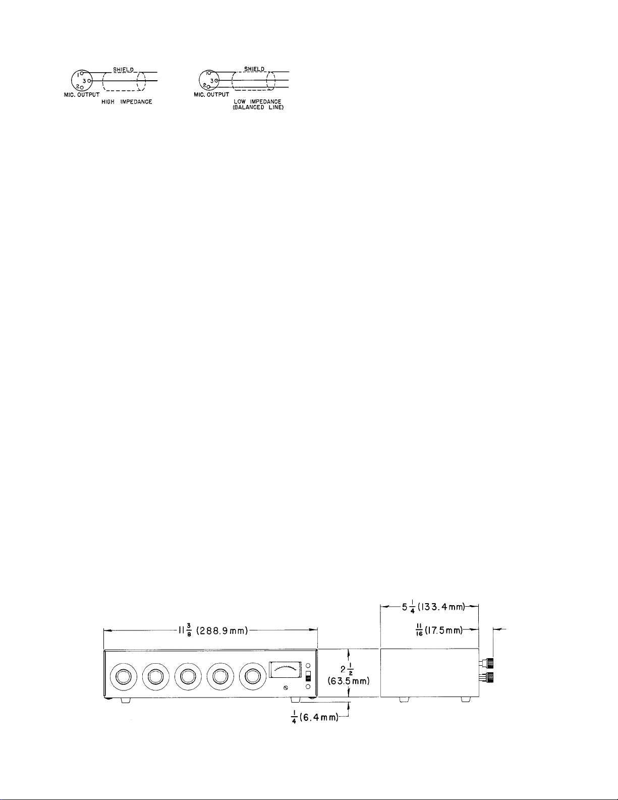
Overall Dimensions: See Figure “B.”
Weight: 3 Ibs. 2 ozs. (1.4 kg)
Operating Temperature:
-7°C (20°F) to 57°C (135°F)
Guarantee: This Shure product is guaranteed in
normal use to be free from electrical and mechanical
defects for a period of one year from the date of
purchase. Please retain proof of purchase date. This
guarantee includes all parts and labor.
Shipping Instructions: Carefully repack the unit
and return it prepaid to the factory. If outside
the United States, return the unit to your dealer or
Authorized Shure Service Center for repair. The unit
will be returned to you prepaid.
OVERALL DIMENSIONS
FIGURE B
2
Page 3

VU METER
When the METER SENSITIVITY switch (on rear
panel) is on the 0 VU = 8 dbm FIXED position, an
output of 8 dbm on the 600 ohm line output
(loaded with 600 ohms), reads 0 VU on the meter.
When the METER SENSITIVITY switch is in the
0 VU VARIABLE position and the 0 VU LEVEL
ADJUST control is maximum (fully clockwise), an
output of 4 dbm on the 600 ohm line output (loaded
with 600 ohms) reads 0 VU on the meter; at minimum position of the 0 VU LEVEL ADJUST, fully
counter clockwise, an output of approximately -20
dbm on the 600 ohm line output (terminated in
600 ohms) reads 0 VU on the meter.
The variable position on the meter sensitivity switch
allows the VU meter to read 0 VU for outputs
ranging from -20 dbm to +4 dbm (600 ohm
line terminated), by adjusting the 0 VU level adjust
(screw driver adjustment on rear panel). To calibrate
the VU meter properly in applications where a level
other than the fixed level is needed, set the
VOLUME control on the M63 until the meter deflects to the 0 VU position on the loudest peaks,
then adjust the 0 VU LEVEL ADJUST control for
the desired output signal level. The LEVEL ADJUST
control attentuates all outputs simultaneously (except
HEADPHONES), while the internal circuitry operates
at the proper level to insure good signal-to-noise
ratio.
ACCESSORY 30 V.D.C.
The rear panel jacks (located near power cord)
provide 30 volts DC for accessories such as the
Model A68P Phono Cartridge Preamplifier. These
jacks also are used as a power input when using
the A67B Battery Power Supply.
CONTROLS
Volume Control
Front panel control designated VOLUME controls
overall output of both high level inputs and functions as a master volume control. When the input
device has a volume control of its own, the best
signal-to-noise ratio is obtained by turning up
that control as high as possible without encountering distortion, keeping the M63 VOLUME control
low.
FREQUENCY IN HERTZ
FREQUENCY RESPONSE IN db–TONE CONTROL CURVES
LO-CUT AND HI-CUT SET ON FLAT POSITION.
FIGURE C
Filter Controls
Front panel controls designated LO CUT (Hz) and
HI CUT (Hz) are continuously variable low pass and
high pass filters (6 db per octave) with a typical
response function as shown in Figure D.
FREQUENCY IN HERTZ
FREQUENCY RESPONSE IN db-LO-CUT AND HI-CUT
CONTROL CURVES BASS AND TREBLE CONTROLS SET AT
12 O’CLOCK POSITION.
FIGURE D
Combining Tone and Filter Functions
The BASS and TREBLE control response characteristic and the LO CUT and HI CUT response
characteristic may be combined to obtain a variety
of overall curves, sometimes needed for special
effects involving room acoustics, equipment equalization, etc. Figure E shows an example of com-
bining these functions.
Tone Controls
Front panel controls designated BASS and TREBLE
are standard function tone controls having a re-
sponse characteristic as shown in Figure C.
FREQUENCY IN HERTZ
FREQUENCY RESPONSE IN db–COMBINING TONE
CONTROL AND FILTER CURVES.
FIGURE E
3
Page 4

In this case, the upper dashed lines show BASS and
TREBLE control position; the lower dashed lines
show HI CUT and LO CUT control settings. The
solid curve is the combined resultant response of all
settings. The resultant response is obtained by
subtracting the lower curve (in db) from the upper
set of curves. For instance, at 100 Hz the lower
curve is 9 db below the 0 Reference line; subtract
9 db from the upper curve at 100 Hz (lowering it to
5 db above the 0 Reference).
The resultant curve shown might be typical of a
sound system where low frequency noise was a
problem (stage noise, etc.) and the room was relatively dead (heavily draped and carpeted). The
low frequency roll off would keep objectionable
thumping noises to a minimum, while the slight
increase in response at 200 Hz will keep the system
from sounding tinny. The rise in the high frequencies
will add some presence so voices or music will have
added clarity.
This is only one example of the response curves
available with the M63. An individual calculation
can be done in this manner for the other resultant
curves.
end for interconnecting an M63 and an M68 Series
Mixer.
A68C OUTPUT CABLE KIT
The A68C Output Cable Kit provides a variety
of output interconnection cables for use with the
M63. Included are: one 15-foot (4.6m) two-conductor shielded cable with professional three-pin
male and female audio connectors*, one 12 in.
(305 mm) two-conductor shielded cable with professional three-pin female audio connector* and
Hubbell twist-lock plug; one 12 in. (305 mm) singleconductor shielded adapter cable with professional
three-pin female audio connector* and Amphenol
type MCI connector; and one phone plug adapter
for use with MCI connector.
*Designed to mate with Cannon XL series, Switchcraft A3 (Q.G.)
series or equivalent connector.
A68R RACK PANEL KIT
The kit consists of a 19 in. x 3½ in. (483 mm x
89 mm) precut rack panel and necessary hardware
for rack mounting of the M63 with its cover in
place.
OPTIONAL ACCESSORIES
A68P PHONO-PREAMPLIFIER
The A68P is a monaural pre-amp which may be used
to convert an input of the M63 to an equalized
phono input. It provides both equalization and
preamplification, and is powered from the 30-volt
DC power take-off provision.
A68M MICROPHONE PREAMPLIFIER
The A68M Microphone Preamplifier provides a
microphone input, either balanced low or high
impedance, or a balanced bridging line input to
the M63. The A68M output cable is connected to
one of the M63 inputs. The A68M mounts on the
left side of the M63 and receives its power from
the M63 30-volt DC jacks.
A68S STACKING KIT
This accessory consists of brackets for vertical stacking of an M68 Series Mixer and an M63 (or any
combination of Shure Mixers, or Controllers). An
interconnecting cable for combining units is included.
A68SC INTERCONNECTING CABLE
This cable is a 12 in. (305 mm) long single-con-
ductor shielded cable with a phono plug on each
A68L LOCKING PANEL
This panel fits within the front hood of the M63
cover and locks in place to prevent tampering with
the front panel controls.
A67H HANDLE/TILT STAND
The A67H provides a convenient means of tilting
the M63 to permit better panel visibility and
greater ease of operation in some conditions. In
the locked (tilt) position, the front panel will be
elevated about 20°. In the free position, the A67H
serves as a rugged carrying handle.
A67B BATTERY POWER SUPPLY
The A67B eliminates the need to connect the M63
Mixer to a wall outlet. The battery complement
is three Eveready Type 222, 216, or equivalent 9
volt batteries. At room temperature, battery life
is approximately 10 hours.
AC60 ATTACHÉ CARRYING CASE
This case is compartmentalized and foam lined for
an M63 and as many as four microphones, cables,
adapters, and other accessories.
4
Page 5

LAMP REPLACEMENT
DIODE, SILICON, 1N4002 OR EQUIVALENT
LAMP, PILOT, #47, 6.3 V.A.C.
NPN TRANSISTOR, SILICON, SELECTED HIGH GAIN,
OR T.I. 2N3711.
PNP TRANSISTOR, GERMANIUM TYPE 2N404A
POTENTIOMETER, 50K, AUDIO TAPER
LOW NOISE, SIMILAR TO MOTOROLA MPS 6521
4
RKC21
86A404
SHURE PART NO. SHURE KIT NO. QTY. IN KIT DESCRIPTION
1 NPN TRANSISTOR, SILICON, T.I. TIS97
4
RKC9 4
RKC12
95A466 RKC7
95A499 RKC80 1 METER, 200 uA. D.C. F.S.
86C349
86A336
POTENTIOMETER, 1K, LINEAR TAPER
NPN TRANSISTOR, SILICON, T.I. TIS92
1 POTENTIOMETER, 50K, LINEAR TAPER
1 POTENTIOMETER, 100K, REVERSE AUDIO TAPER
1
1
1
RKC3
86A342
46A021
46A022
46A023
4 SWITCH, SLIDE, DPDT
RKC10
46A024
55A54
1 NPN TRANSISTOR, GERMANIUM TYPE 2N1605A
1
RKC65
86A335 RKC66 1 PNP TRANSISTOR, SILICON, T.I. TIS93
86A334
86A343
SWITCH, SLIDE, DPDT, 3 AMP.
TRANSFORMER, POWER (M63-2E)
1 TRANSFORMER, POWER (M63)
1
1 TRANSFORMER, OUTPUT
RKC15
RKC18
RKC16
51A231
51A253
51A233
55B103 1
AGAINST SIDES OF CUT OUT.
REMOVE COVER.
REMOVE SCREW AND NUT BETWEEN VU METER BRACKETS.
ON BACK, TWO ON BOTTOM,
REMOVE 4 PHILLIPS HEAD SCREWS RETAINING COVER- ONE ON FRONT, ONE
DISCONNECT A.C. CORD.
2.
1.
3.4.5.
ARE INTERCHANGEABLE.
GENTLY PUSH VU METER FROM FRONT AND LIFT UP CLEAR OF CHASSIS.
SOCKETS MAY NOW BE PUSHED CLEAR OF CHASSIS AND THE #47 LAMPS
REMOVE SCREWS RETAINING LAMP SOCKETS FROM UNDERSIDE OF CHASSIS.
REPLACED. IT IS ADVISABLE TO REPLACE BOTH LAMPS WHEN I BURNS OUT.
BRACKETS MAY FALL OUT. NOTE THEIR POSITION IN CUT OUT. BRACKETS
6.
REPLACE LAMP SOCKET AND LOOSELY FASTEN SCREWS.
7.
8.
THEM. VU METER SHOULD FIT EASILY INTO CUT-OUT IF POSITIONED
SLIDE VU METER INTO CUTOUT. SHOULD LAMPS BE IN THE WAY, MOVE
PLACE 2 VU METER BRACKETS IN CUT-OUT, PUSHING THEM FIRMLY
9.
PROPERLY. DO NOT FORCE.
10.
METER. DO NOT OVER TIGHTEN. (SEE DIAGRAM FOR REPLACEMENT.)
HOLDING VU METER FIRMLY AGAINST BACK SIDE OF CHASSIS FRONT PANEL,
SQUEEZE BRACKETS AGAINST METER BODY. INSERT SCREW THROUGH HOLES
IN BRACKETS AND SECURE WITH NUT. NUT GOES ON RIGHT SIDE OF
CHECK POSITIONING OF LAMPS, AND TIGHTEN THEIR TWO MOUNTING
REPLACE COVER AND SECURE WITH SCREWS.
11.
12.
13.
PARTS PLACEMENT
ITEM
M101
D1, D2, D101, D102
L101, L102
Q1-Q6*
Q7
Q10**, Q8
Q9**
Q11, Q14
Q12, Q13
R102
R101
S103
R103, R104
R105, R106
S101, S102
FROM SHURE BROTHERS. INCORPORATED.
**FOR REPLACEMENT, PURCHASE Q9 AND Q10 AS MATCHED PAlR TIS92M-TlS93M.
* TO INSURE LOW NOISE FIGURE, PURCHASE REPLACEMENTS FOR Q1-Q6
T101
T102
PRINTED CIRCUIT
BOARD ASSEMBLY
Page 6

P.C.
WIRING BOARD
COMMON GROUND BUSSES
DENOTES D.C. VOLTAGES
DENOTES A.C. VOLTAGES
CHASSIS
GROUND
ALL VOLTAGES MEASURED WITH A.C. LINE =
ALL CAPACITORS IN Mfd AND 100 VOLTS
NOTES:
1.
OTHERWISE SHOWN.
ELECTROLYTIC CAPACITORS SHOWN IN
OR MORE UNLESS OTHERWISE SHOWN.
Mfd x VOLTS.
3. THE FOLLOWING SYMBOLS DENOTE:
2. ALL RESISTORS 10%, ¼ WATT UNLESS
120 V. (M63) OR 240 V. (M63-2E),
4.
VOLUME CONTROL MAXIMUM, TONE
CONTROLS FLAT, INPUT SUCH THAT UNIT IS
AT 1 KHZ. D.C. VOLTAGES MEASURED WITH
20K OHM / VOLT VOM. A.C. VOLTAGES
DELIVERING 8 DBM INTO 600 OHM LOAD
MEASURED WITH 1 MEGOHM A.C. V.T.V.M.
VALUES ARE TYPICAL AND MAY VARY ±15%.
OF PRINTED CIRCUIT BOARD ASSEMBLY.
ALL COMPONENTS AND CONNECTIONS
ENCLOSED BY DASHED LINES ARE PARTS
5.
CIRCUIT DIAGRAM
MODEL M63 AND M63-2E AUDIO MASTER
 Loading...